CTI 2572
ETHERNET TCP/IP ADAPTER MODULE
TECHNICAL OVERVIEW
Version 1.1
CTI Part # 062-00156
'???#???(?????????"#'
Copyright 1993, 1998 Control Technology Inc.
All rights reserved.
This manual is published by Control Technology Inc., 5734 Middlebrook Pike, Knoxville, TN 37921. This manual contains references to brand and product names which are tradenames, trademarks, and/or registered trademarks of Control Technology Inc. and Siemens AG. Other references to brand and product names are tradenames, trademarks, and/or registered trademarks of their respective holders.
DOCUMENT DISCLAIMER STATEMENT
Every effort has been made to ensure the accuracy of this document; however, errors do occasionally occur. CTI provides this document on an "as is" basis and assumes no responsibility for direct or consequential damages resulting from the use of this document. This document is provided without express or implied warranty of any kind, including but not limited to the warranties of merchantability or fitness for a particular purpose. This document and the products it references are subject to change without notice. If you have a comment or discover an error, please call us toll-free at 1-800-537-8398.
CTI 2572 Technical Overview Manual

PREFACE
This Technical Overview Manual provides an introduction to CTI 2572 Ethernet TCP/IP Adapter and to the networking specifications used with the module. The manual is intended for those individuals who wish to gain a fundamental understanding of the 2572, Ethernet, TCP/IP, and SIMATIC TI505 PLC command interfaces.
This manual is organized as follows:
Chapter 1 describes the features of the 2572;
Chapter 2 provides an overview of local area network topologies;
Chapter 3 reviews Ethernet physical media and data link formats;
Chapter 4 provides an overview of higher level local area network protocols;
Chapter 5 discusses TCP/IP and related protocols
Chapter 6 covers SIMATIC TI505 command protocols.
Individuals interested in more in-depth information regarding Ethernet and TCP/IP may wish to read one of the several excellent technical books available on the subject. These include
Internetworking with TCP/IP Vol I, II, and III by Douglas E. Comer (Prentice-Hall, 1991), TCP/IP and Related Protocols by Uyless Black (McGraw-Hill, 1992), and The Simple Book
Book by Marshall T. Rose (Prentice Hall, 1991).
Please refer to the CTI 2572 Installation and Operation Guide for specifications and additional information about the 2572 message interface.
CTI 2572 Technical Overview Manual
CHAPTER 1. INTRODUCTION
personal computers running programming software, such as TISOFT, can access the PLC memory via these ports. These ports operate concurrently with the Ethernet ports.
An array of diagnostic LEDs indicate operational status of the module, activity on the Ethernet and serial ports, and the status of the Ethernet connection (link beat status, AUI active, collisions, and 10BaseT reversed polarity).
The 2572 requires no user programming of the module. The initial baud rates of the serial ports may be set by switches. All options are set by switches on the module or via word values set by PLC logic.
1.2 2572 Functions
Server Mode
In Server Mode, the module responds to PLC commands embedded in the TCP/IP packet. The initiating device (usually a computer or a 2572 operating in client mode) encapsulates the PLC command in the TCP/IP protocol and transmits it to the IP address of the 2572. The 2572 retrieves the command from TCP/IP and formats a corresponding request to the PLC processor. When the 2572 receives the response from the PLC processor, it encapsulates the response in the TCP/IP protocol and transmits it back to the IP address which sent the initial command.
No PLC programming is required to support server mode. However, the initiating device must encapsulate the proper command in the TCP/IP protocol and must properly process PLC responses which the 2572 embeds in TCP/IP. Many operating systems contain support for TCP/IP. Unix contains native TCP/IP support; IBM OS/2 and Microsoft Windows provide optional TCP/IP support. MS DOS does not directly support TCP/IP, but several companies offer DOS TCP/IP drivers.
Client Mode
In Client Mode, the 2572 can initiate a TCP/IP message. PLC logic is used to tell the 2572 what to send, where to send it, and when to send it. Using 2572 Client Mode, the local PLC can read and write memory in other remote PLCs or it can send messages to supervisory computers based on events detected by the PLC (alarm detection, data logging, etc.). Since a 2572 can operate as both a server and a client, multiple PLCs (each with a 2572), can participate in peer to peer communications.
Serial Redirect
Serial Redirect is a very powerful feature which routes data received at a serial port on the module to another node on the network. Once the serial port has been configured for the type of service and a destination address has been established, the 2572 will encapsulate the serial port data in TCP/IP and send it to the destination. Replies from the destination address will be routed back to the serial port. Using Serial Redirect, devices which normally communicate with the programming port of the PLC can access remote PLCs. For example, a PC running TISOFT could download programs to other PLCs on the network.
2
CTI 2572 Technical Overview Manual

CHAPTER 2. LOCAL AREA NETWORK OVERVIEW
Local Area Networks (LANs) grew from the need to interconnect many intelligent devices in a non-proprietary manner. Today, the most widely used LAN standards are Token-Ring (IEEE 802.5) and Ethernet (IEEE 802.3). Token Bus (IEEE 802.4), was proposed by GM in the late 80???s as a part of the Manufacturing Automation Protocol (MAP). Token Bus has seen limited use, primarily due to cost and installation difficulty. It is briefly discussed in this document to provide a more complete perspective of factory networking alternatives.
2.1 Master/Slave vs. Local Area Networks
Master/slave networks are commonly used in factory floor communications. These networks use a master station (computer or /controller) and multiple slave devices (such as controllers, terminals, or readers). The master station polls each slave unit on the network in turn, requesting services or information. After the slave performs the task (or indicates that it cannot), the master polls the next slave. This scheme works reasonably well when there are few devices on the network. However, as the size of the network grows, more and more master processor resources and network bandwidth must be devoted to the "overhead" of polling. This overhead limits throughput and lengthens response time, especially since most master/slave networks operate at a data rate of 115 K bits/sec or less.
Local area networks (LANs), on the other hand, do not have a master station. All stations on the network can initiate a message. Standard rules for media access determine when a given station may send a message. Media access rules usually involve passing a token or listening for traffic on the line. As a result, the overhead of a typical local area network is much lower than a master/slave network. This characteristic, coupled with much higher signalling rates (10 - 16 Mb) provides much higher throughput and allows many more devices to be connected to the network. Because there is no master station, there is no single point of failure.
Each master/slave network tends to use a different protocol, partially because there is no generally accepted standard. The protocol is typically determined by the primary equipment manufacturer and in some cases the protocol may be proprietary, subject to copyright or patent laws. As a result, most master/slave networks have very poor multi-vendor inter-operability. Conversely, LANs such as Ethernet and Token-Ring have protocols that are well specified and documented by standards bodies such as IEEE and are supported by a wide number of vendors.
2.2 IEEE 802.5 (Token-Ring)
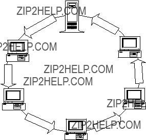
Token Ring (IEEE 802.5) uses a ring topology. Each station on the network has two connections - one to the "downstream" station and one to the "upstream" stations. Each station receives network data from the downstream station and passes it to the upstream station. The data circulates through the network until it reaches the initiating station, which validates that it was correctly sent though the network. In practice, rather than wire directly between each station, the stations are wired into a central hub. This approach allows stations to be added by plugging them into the hub, where the plug mechanically inserts the station into the ring. Token ring operates at 4 or 16 M bits/sec using shielded twisted pair media. Fiber optic cable may be used for interconnecting hubs.
Server
PC
PC
PC
Figure 2 Token Ring Topology
Token Ring (802.5) uses a "token" which is passed among the stations on the network. When a station has a token, it can transmit. When it is through transmitting data, a station sends the token to the next "upstream" station.
The primary benefit of token ring is that it provides a very consistent level of network performance, since there is a maximum amount of time a token can be held. Token Ring response is sometimes referred to as deterministic, meaning that the response time can be precisely calculated. At higher levels of network loading, Token-Ring may provide greater sustained throughput than Ethernet or Token-Bus.
On the other hand, token ring is costly (about 4 to 5 times more than Ethernet) and its technology is closely tied to proprietary IBM technology. In some situations, the ring topology of token-ring networks may not be as well suited to the factory floor as a bus topology.
4
CTI 2572 Technical Overview Manual
2.3 Ethernet and IEEE 802.3
Officially, "Ethernet" is the name of a CSMA/CD network developed at Xerox. It was jointly documented by Digital Equipment Corporation (DEC), Intel, and Xerox in a 1982 specification for Ethernet Version 2. This specification is commonly called Ethernet II or "Blue Book" Ethernet for the color of the specification cover. Later, the IEEE developed a specification for a CSMA/CD local area network based on Ethernet II. This specification, called 802.3, is fully compatible with Ethernet II at the physical layer (e.g. hardware, connectors, and media). However, there are some formatting differences in the data link packet (discussed in the next section).
Although the specifications are not totally compatible, the distinction between "Ethernet" and 802.3 have become blurred. Consequently both are commonly referred to as Ethernet. In this document, except where specifically noted, the term Ethernet will refer to both the "Blue Book" (Version 2) and the 802.3 specification.
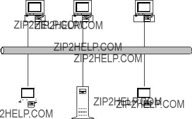
Ethernet stations are connected in a bus arrangement, all stations share a common connection. When a message is transmitted on the network, all attached devices receive it. The Ethernet standard supports a variety of media, including coaxial cable, twisted pair, and fiber optics.
another station is transmitting. If the signal is detected, the station waits until it detects no carrier, then transmits. It is possible that when there is no carrier (no one is transmitting) more than one station can attempt to transmit data at the same time. This condition is referred to as a collision. Ethernet stations can detect this condition (Collision Detection), wait a random amount of time, then retry.
Ethernet has a number of important benefits. Since it is widely used, Ethernet adapters are very inexpensive when compared to other alternatives. It has a very flexible topology and media selection (coaxial cable tap, twisted pair hub, or fiber optic hub). In addition, it provides excellent response and throughput at typical utilization levels.
The primary disadvantage of Ethernet is that the response time is not consistent under widely varying loads. As the network loading increases above 50% , collisions occur more frequently and the network response time increases. In practice, most large busy networks use bridges to reduce the number of collisions. Bridges are discussed in the next chapter.
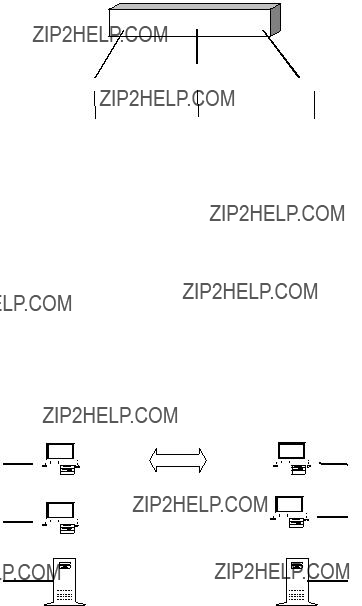
2.4 IEEE 802.4 (Token Bus)
Token-Bus is a LAN standard developed in conjunction with the General Motors Manufacturing Automation Protocol (MAP) effort. All Token Bus stations are connected a to a common wire, in this case coaxial cable. Like Token-Ring, a station can transmit only when it has received the token. The IEEE 802.4 Token-Bus standard supports both a broadband network and a carrierband network using RF (Radio Frequency) technology. The broadband network (envisioned as the factory "backbone") supports multiple channels which could contain different data types (e.g. analog video and digital data) and operates at 10 Mb. The single channel carrierband supports up to 32 devices at a 5 Mb data rate.
Token Bus was selected by the MAP committee because it provided a bus topology (which some consider to be a better plant floor topology) and it offered the consistent, deterministic response time inherent in token passing schemes. RF technology was selected for noise immunity and because it provided the opportunity for a single factory cabling system to carry both digital data and analog video.
The big disadvantage of Token Bus is cost and availability. Not only are the adapters very costly (up to 30 times the cost of Ethernet) but RF transmission is very sensitive to factors such as cable length, amplifier alignment and termination impedances - making it expensive to install and maintain.
2.5 Future Technologies
While both Token-Ring and Ethernet are excellent for transferring typical factory data, none have the capacity to transmit high bandwidth information such as full motion video. There are a number of emerging LAN standards which promise to offer this capability. These include FDDI (Fiber Distributed Data Interface), CDDI (Copper Distributed Data Interface), ATM (Asynchronous Transfer Method), "Switched" Ethernet, and "Fast" Ethernet. These will offer signaling rates in the range of 100 Mb.
At this point in time, it is difficult to predict which technology will prevail as the new high speed standard. Many experts speculate that future networks will incorporate both current (medium speed) and high speed LAN technology.
6
CTI 2572 Technical Overview Manual
2.6 Summary
Older master/slave networks are rapidly being replaced by standard LANs which provide better performance, multi-vendor support, and integration with information networks. Of the current LAN standards, Token-Ring and Ethernet have the significant market share. Token Bus, because of the cost and complexity, has never become a major contender for the factory LAN market.
In general, Ethernet offers the most cost-effective and flexible factory floor networking solution available today. In a properly designed factory network, Ethernet provides excellent performance, reliability, and manageability. Since Ethernet is used with the 2572, it is discussed in more detail in the following section.
CHAPTER 3. ETHERNET OVERVIEW
3.1 ISO Reference Model
Modern network implementations separate data communication functions into layers. Each layer performs a specific set of services and interacts with layers above and below in a well defined way.
In 1984 the International Standards Organization published the Open Systems Interconnection (OSI) Reference model. Although there are few, if any, strict implementations of the entire seven layer model, it is commonly used as a conceptual reference when discussing networking software. The OSI model is briefly described below:
Layer
Layer 7
Application
Layer 6
Presentation
Layer 5
Session
Layer 4
Transport
Layer 3
Network
Layer 2
Data Link
Layer 1
Physical
Function
Provides application services such as file transfer, virtual terminal, and directory services.
Resolves differences in data representation between the communicating applications
Synchronizes communications between applications
Provides reliable data transfer from end node to end node.
Translates physical addresses into logical addresses and routes packets to the destination node.
Places messages into data frames and manages access to the media.
Defines the electrical and mechanical characteristics of the transmission media .
The Ethernet specifications describe both the Physical layer (cabling, connectors, and topology) as well as the Data Link (Medium Access) layer. As a result of this complete specification, Ethernet equipment from various vendors can be used on the same network. Ethernet is the most widely used local area network in the world and it is continuing to gain market share due to its low cost and flexibility. One of the fastest growing areas in Ethernet installations is the factory floor.
10Base5 (Thick Coax) Topology
Ethernet
Station
Ethernet
Station
AUI Port
AUI Port
Transceiver
10Base5 (Thick Coax)
Transceiver
3.2 Ethernet Topologies and Media - Physical Layer
Ethernet Version 2 and IEEE 802.3 are fully compatible at the physical level. Therefore the formal IEEE 802.3 specification is used to describe all Ethernet media. The 802.3 specification provides for a variety of topologies and media. All commonly used media operate at 10 Mb. Specified media/topology can be used interchangeably and can be intermixed on the same network. Ethernet media specifications include "thick" coax (10Base5), "thin" coax (10Base2), twisted pair (10BaseT), and Fiber Optics (FOIRL). The specification provides for a media independent port on Ethernet adapter cards known as an Attachment Unit Interface (AUI). Media specific transceivers attach to the AUI. In addition most adapters provide at least one native media attachment (usually 10Base2 or 10BaseT).
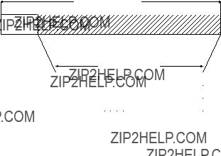
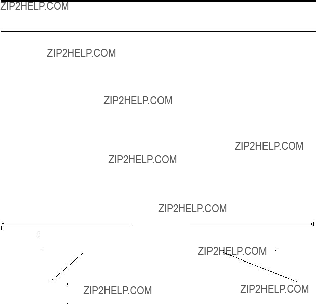
10Base5 "Thick" Coax
10Base5 was the original Ethernet media. It is capable of cable runs up to 500 meters (approximately 1500 feet). This distance may be extended by the use of a repeater. Ethernet stations (nodes) are attached to the 10Base5 cable in a tap fashion. The transceivers are mounted on the cable and a cable is run from the transceiver to the AUI port on the adapter. Although there are numerous installations in place using 10Base5 cabling, new installations tend to use other, more cost effective, cabling media.
Transceiver
AUI Port
Ethernet
Station
Figure 4
often referred to as "cheapernet" due to this low cost. 10Base2 cabling uses a "T"
connector at each tap with a 50 ohm terminator at each end. The "T" connector may be attached to a 10Base2 transceiver (and the network adapter card via the AUI port). Alternately, the network adapter may provide a direct attachment for 10BaseT.
10
CTI 2572 Technical Overview Manual
10BaseT Port Station
Although 10Base2 cabling avoids the expense of a hub, it presents a major disadvantage for large installations. Because "T" connectors are used at each tap, there are two connections to the main cable for each node. Should a problem develop with the "T" connection, communications between stations above the connector and stations below the cable would be lost. In addition, if you need to add a station in the middle of a cabling run, you must splice in another connection. Usually this involves taking the network down for a period of time.
10BaseT Unshielded Twisted Pair (UTP)
Recent developments in Ethernet technology have allowed the use of Unshielded Twisted Pair (UTP) cabling. UTP cabling is essentially high grade telephone cable terminating in a modular plug (RJ-45). 10BaseT uses a hub technology; network stations are connected to the hub via the UTP cabling. The hub internally connects all the ports together into a bus. Active components
in the hub enhance signal quality by re- Figure 6 aligning packets and retransmitting
signals. Network attachments are made via 10baseT transceivers attached to the
AUI port or directly via a RJ-45 jack on the adapter.
10BaseT Hub
10BaseT (Unshielded Twisted Pair) Topology
The 10BaseT standard allows each UTP cable from the hub to be up to 100 meters (about 300 feet) in length. Hubs can be cascaded or interconnected to extend the total span of the 10baseT network. Stations can be added to a hub by simply running a cable from the hub to the new station. The new cable can be attached to the hub while the network is active.
One of the key benefits of the 10baseT hub technology is that it provides a sound basis for network management. For example, the hub can detect problems (such as excessive collisions) on a given port and can disconnect the problem port, preventing that one segment from adversely affecting other stations. In addition, the hub can collect data regarding network traffic for subsequent retrieval and analysis by a network management program. Many hubs can be configured to send an alarm message to the network management station if a predetermined condition is encountered.
FOIRL (Fiber Optic)
Like the 10BaseT standard, the fiber optic cabling scheme uses a hub technology. Network stations are connected to the hub via point to point fiber optic connections. The fiber optic cable is attached to the network adapter using transceivers connected to the AUI port. A fiber optic cable run can extend up to 1 km.
Fiber optics is often used where longer distances, noise immunity, and lightning protection are required. This includes communications within buildings on a factory campus and as a "backbone" within a single large building. Except for the media, fiber optic hubs are essentially equivalent to 10BaseT hubs.
Bridges.
Fiber Optic Hub
Figure 7 Fiber Optic Hub
As mentioned earlier, Ethernet uses
segment. Most bridges can automatically learn which transmissions need to be routed across the bridge. In addition, bridges can be used to extend the distance of an Ethernet network, since they perform a repeater function also.
12
CTI 2572 Technical Overview Manual
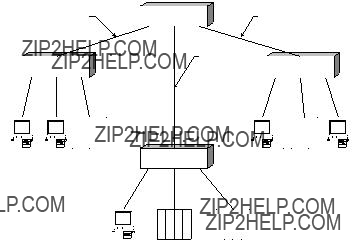
Multiple media types may be used on the same network. In larger installations it is very common for distributed 10baseT hubs to be interconnected via a fiber optic hub. The fiber optic "backbone" provides extended distance and additional noise immunity while the 10BaseT cabling provides a simple connection to nodes within a local area.
The flexibility of cabling schemes and interconnection options is one of the strengths of the Ethernet physical layer. You may wish to consult your network vendor for additional details on the numerous options available.
3.3 Ethernet Protocol - Data Link Layer
Figure 9 Mixed Ethernet Media
Media Access
As previously presented, Ethernet uses a CSMA/CD (Carrier Sense Multiple Access with Collision Detection) as a media access scheme. When a station has a message to transmit, it monitors the line for a carrier signal (which indicates that another station is transmitting). If there is no carrier signal, the station transmits the data. It is possible that more than one station will attempt to transmit at the same time; when this occurs the signals will "collide". When transmitting Ethernet stations detect a collision, each waits a random amount of time, then re- transmits. Should a second collision occur, the stations back off exponentially until the transmissions are successfully completed. In actual practice, 3 or more collisions are a rare occurrence. The fact that stations delay a random amount of time when a collision occurs results in the network being "non-deterministic." (response time cannot be precisely calculated). As a practical matter, the Ethernet media access scheme is elegantly simple and performs well with reasonable network loading.
Ethernet Version 2 and IEEE 802.3 Packet
Ethernet Version 2 and IEEE 802.3 transmit data as "packets" which can vary from 64 to 1518 bytes in length. Each packet contains the source address, destination addresses, the application data, and a checksum. At this point the Ethernet II and 802.3 specifications diverge.
CTI 2572 Technical Overview Manual
14
Frame w/ SNAP Header
802.3
Figure 10
= 000
03 = UI
0800 = IP
170 = SNAP
170 = SNAP
Code
Control
SAP
SAP
Organization
EtherType
LLC
Source
Destination
1 Byte
1 Byte
1 Byte
2 Bytes
3 Bytes
Data
IEEE 802.2 LLC Header
Data
CRC
Data
Length
Source Address
Destination
Address
4 Bytes
2 Bytes
6 Bytes
6 Bytes
Variable (up to 1500 Bytes)
Since IEEE 802.3 does not contain any information which identifies the upper level protocol being used, it is usually combined with the 802.2 Logical Link Control (LLC) specification. The LLC header does provide information about the upper layer protocol and is placed in the first few bytes of the 802.3 data area.
However, the 802.2 specification allows only one byte for the upper level protocol identifier (called a Service Address Point). Thus, a special version of 802.2 LLC called SNAP (Sub Network Access Protocol) was created to contain the 2 byte TYPE field used in the Ethernet II packet.
Even though the Ethernet II and 802.3 packet formats are different, there are generally accepted conventions for placing information in the Type/Length field which allows communications software to differentiate between the two. As a result, both packet types can co-exist on the same network. However, a node which sends and receives only Ethernet II packets cannot communicate with a node which sends and receives only 802.3 packets.
The Ethernet Version 2 standard defines the packet as follows:
The type field is used to define the upper level protocol being used (e.g. TCP/IP, DEC LAT, etc.).
The IEEE 802.3 specification substitutes a length field for the type field and has the following format:
As you may notice, the Ethernet II format provides the Ethernet type information in 2 bytes while the 802.3 SNAP requires 8 bytes to provides this information. Consequently, most TCP/IP installations use the Ethernet II frame format. The 802.3 SNAP format is typically used only when strict 802.3 compatibility is required.
3.4 Ethernet Addresses
Every Ethernet adapter board has a unique 48 bit physical assigned by the manufacturer of the adapter board. The first 24 bits, assigned by IEEE, are unique to the hardware manufacturer. The manufacturer then assigns a unique number to every adapter board using the remaining 24 bits. When a network adapter recognizes a packet containing its address in the "destination" field, it processes the packet; otherwise the adapter ignores it. Special address conventions allow a message to be broadcast to all stations or "multicast" to a group of stations.
3.5 Requirement for Higher Level Protocols
Based on the information presented in this previous section, it might appear that Ethernet, by itself, is sufficient for local area network communications. It would seem that application software could simply insert the destination address and the application data in the Ethernet packet and send it. The receiving software would be presented with the packet by Ethernet and would remove and process the application data. However, there are several problems with this approach:
1)The application programming interface at the data link level is fairly complex.
2)There are no widely available standard application program interfaces such as Berkeley sockets at the data link level.
3)Since the Ethernet physical address is determined by factory hardware settings, changing out a 2572 or a PC Network Interface Card will change the physical address of a PLC or a PC. Without a higher level protocol like TCP/IP, maintaining address data would be up to the application program.
4)The application would be local network dependent; the data could not be routed across different network types.
As a result, additional upper layer protocols such as TCP/IP are required to simplify programming, to provide additional services, and to provide a level of abstraction from the physical network. TCP/IP and upper layer protocols are discussed in the next section.

CHAPTER 4. NETWORK PROTOCOLS
4.1 Connectionless vs. Connection Oriented Protocols
In most networking discussions you will find references to connectionless and connection- oriented services. The following analogy may help you understand the features and advantages of each.
Connectionless Protocols
Connectionless services may be compared to the standard U.S. mail. You place a letter in an envelope and mail it. There is no need to notify the recipient that you are mailing the letter and no requirement that the post office confirm that the letter was delivered (although they may notify you eventually if the letter could not be delivered). You may ask the recipient to respond. If they do not respond within a period of time, you can take some followup action (like sending another letter). If you mail several letters to the same recipient, there is no guarantee by the post office that they will be delivered in the same sequence that they were mailed or that all of the group will be delivered.
Connectionless network protocols work the same way. The user software sends a packet (datagram) to another node on the network. There is no requirement to establish communications with the recipient prior to sending the packet nor does the network protocol confirm delivery (although the protocol may notify the user if the datagram could not be delivered). The application software may expect or request a reply from the recipient. If no reply is received within a specified period of time (timeout), the application software may re-try. If several datagrams are sent, there is no guarantee by the network that they will arrive in the same sequence that they were sent or that all will be delivered.
Connectionless protocols are frequently described in network terminology as unreliable. Despite the emotional baggage that this term carries, it simply means that the protocol used at this level will not guarantee that packets will be delivered or that notification will be given if a packet cannot be delivered. A higher level protocol or the application program itself may perform this function.
Connectionless protocols provide several advantages: they make efficient uses of network resources, are much simpler to implement, and require less processor overhead. A connectionless protocol would typically be used to send a command to a PLC to read data from memory.
Connection-Oriented Protocols
Connection-oriented protocols may be compared to a personal telephone call. Before you begin a conversation, you establish a connection by dialing a number and verifying that you are talking to the desired person.
Connection-oriented network protocols work in a similar manner. First, a logical connection is made between user applications. After certain parameters are negotiated and the connection has been verified by both partners, the user applications are allowed to send data. Periodically, the recipient acknowledges delivery of a group of data. The sending software examines the acknowledgement , determines if any data must be retransmitted, and re-sends it if required. Connection-oriented protocols will notify upper level software if data could not be delivered or if a connection is broken.
Connection-oriented protocols require additional network resources to set up the logical connection. In addition, they require additional processor resources to buffer data and to perform sequence validation. Connection-oriented protocols are sometimes referred to as reliable protocols because the protocol guarantees that the data will be delivered in sequence or that the sender will be notified if the protocol was unable to do so. A connection- oriented protocol would typically be used download a program to a PLC.
4.2 Common LAN Protocols
As discussed in the previous section, the Ethernet specifications cover layer 1 (physical) and layer 2 (data link) of the OSI reference model. Additional protocols are commonly used on local area networks at layer 3 (network) and layer 4 (transport) of the OSI Reference model. The more common protocols in this area are NetBIOS/NetBUEI, IPX/SPX, and TCP/IP.
NETBUEI
NETBUEI (NetBIOS Extended User Interface) is the protocol stack used by Microsoft LAN Manager and IBM LAN Server. More recently, Windows for Workgroups, a Microsoft product, uses NETBUEI.
NETBUEI uses LLC (802.2) to provide both connectionless and connection-oriented services. NETBUEI then implements an IBM/Microsoft proprietary connection-oriented NetBIOS Frames Protocol on top of 802.2. Applications interface to NETBUEI via NETBIOS calls. NETBIOS employs user defined node names to establish a logical connection with another node. The architecture of NETBUEI has the potential for excellent performance but has developed a reputation for requiring significant "tuning" to achieve this performance. Another major problem with NETBUEI is that its architecture does not allow NETBUEI to be routed among different network types.
18
CTI 2572 Technical Overview Manual
IPX/SPX
IPX (Internet Packet eXchange) and SPX (Sequenced Packet eXchange) are proprietary protocols used by Novell Netware. IPX is similar to Xerox???s Internet Datagram Protocol. IPX provides an unreliable connectionless transmission service. Since IPX is classified as an unreliable protocol, upper level command protocols (such as Netware Core Protocol) must provide their own delivery verification. The verification technique involves sending a single request packet and expecting an acknowledgement. If an acknowledgement is not received after a given period of time, a retry is initiated. IPX data packet sizes tend to be small (512 bytes or less), thus a large number of individual packets may be required to transfer data.
SPX (Sequenced Packet eXchange) is similar to Xerox???s SPP(Sequenced Packet Protocol). It provides a connection oriented service that provides high reliability, correctly retransmitting and re-ordering packets when they are dropped or misrouted. SPX is typically used with applications such as print spoolers that transfer large sequential streams of data.
Novell Netware has become a popular networking product, partially because the low overhead of IPX/SPX allowed it to be run on 8088 and 80286 class DOS machines with reasonable performance. More recently, Novell has announced that they will support the TCP/IP as a native Netware protocol.
TCP/IP
Of all the popular LAN protocols, only TCP/IP can be considered to be "open" (i.e. non- proprietary). TCP/IP (Transmission Control Protocol/Internet Protocol) was developed under the auspices of the Defense Advanced Research Project Agency( DARPA) as a standard for interconnecting the variety of military and university research computers and networks. The focus of the TCP/IP designers was to provide a practical , effective, and open-standard protocol. As a result of this design philosophy, TCP/IP has garnered a very large installed base which continues to grow rapidly. TCP/IP has proven to be an effective protocol not only for tying together worldwide networks, but also for local area network communications.
IP (Internet Protocol) is similar to Netware IPX. It provides connectionless node to node routing and packet delivery services. TCP (Transmission Control Protocol) provides connection- oriented services and uses the services of IP to transmit TCP data segments. Other facilities such as TELNET (terminal emulation), SNMP (Simple Network Management Protocol) and FTP (File Transfer Program) use the services of TCP and IP to accomplish their tasks. TCP/IP was chosen as the higher level protocol for the 2572 because:
1)It is a non-proprietary "open" standard,
2)It has a proven track record for performance and reliability,
3)It has been successfully implemented on most major computer operating systems (including Unix, DOS, VMS, OS/2).
The following chapter discusses TCP/IP in more detail.
CHAPTER 5. TCP/IP OVERVIEW
5.1 TCP/IP Components
TCP/IP consists of a hierarchy of related protocols. Upper level protocols are encapsulated in the data structure of lower level protocols.
Figure 11 TCP/IP Data Encapsulation
In a typical application using the 2572, the host computer application sends PLC commands via either TCP (Transmission Control Protocol) or UDP (User Datagram Protocol) services. TCP is used if connection-oriented communications is desired; UDP is used for connectionless communications. The TCP segment or UDP datagram is placed in an IP (Internet Protocol) datagram which is then sent to a 2572 over the network. The receiving 2572 removes the TCP (or UDP) packet from the IP datagram, removes the PLC command from the TCP (or UDP) packet, and transfers the PLC command to the PLC processor. Responses from the PLC are processed in a similar manner.
5.2 Internet Protocol
Internet Protocol (IP) provides a basic packet delivery service. Technically, this service is defined as unreliable, connectionless, and best-effort. Unreliable means that delivery is not guaranteed by the protocol. The packet may be lost, duplicated, delayed, or delivered out of order. Connectionless, as defined previously, means that each packet is treated independently of all others. Finally, best-effort means that IP software makes an earnest attempt to deliver packets and does not discard packets capriciously.
IP defines the structure of the unit of data transfer, called an internet datagram. IP also defines the rules and procedures for routing datagrams, how and when error messages should be generated, and the conditions under which a packet will be discarded. The datagram consists of an IP header and the data from the upper layer protocol. Fields in the datagram header contain control information and the IP address of both the source and the destination node.
IP Address
An IP address is a 32 bit field which uniquely identifies the network and the host computer node. The IP address is conceptually divided into four 8 bit bytes (called octets in some technical publications). An IP address is usually expressed in dotted notation, with one byte expressed as its decimal equivalent. For example, an address containing all 1???s would be notated 255.255.255.255 (see below).
22
CTI 2572 Technical Overview Manual

A typical IP address consists of a network ID portion and a host ID portion. The distribution of the address bytes between network ID and host ID is defined by the address class. Class A uses the first byte for the network ID and the remaining three bytes for the host ID. Class B uses two bytes for the network ID and two bytes for the host ID. Class C uses the first three bytes for the network ID and the last byte for the host ID. The class type is determined by the first few bits of the address. Address classes provide the flexibility to handle both large and small networks while conserving IP addresses. There will be a few networks with a large number of hosts (Class A) and a large number of networks with a small number of hosts (Class C). Some addresses are reserved for special functions, such as broadcast messages.
For a private network using internet protocol, assignment of network/node addresses is up to the individual organization. Organizations with networks connected to the Internet (with a capital I) must obtain the network portion of the IP addresses from a central authority - the Network Information Center. The Host ID portion of the IP address is assigned by the local organization. Thus the Host ID is often called the local portion of the IP address.
Subnet Address Mask
Larger organizations with many internal networks (subnets) may choose to subdivide the local portion of the IP address into a subnet identification and a host ID. For example, an organization with a class B address may choose to use byte 3 as the subnetwork ID and byte 4 as the host ID. The subnetting scheme is defined by a 32 bit Subnet Mask. The mask is set to zeroes in that portion of the address that represents the host ID and is set to ones everywhere else (network and subnetwork portion). A subnet mask for the above example would appear as:
In dotted decimal notation this example would be expressed as 255.255.255.0
Gateways use the IP address to route IP datagrams from the sender host to the destination host. If the hosts are on different networks, the gateway reads the network ID portion of the address and determines how to forward the datagram so that it reaches its destination. In a large internet,
the datagram may actually pass through many gateways before reaching the destination network. IP has defined a comprehensive set of rules for processing datagrams. Among these specifications are the Internet Control Message Protocol (ICMP).
Internet Control Message Protocol (ICMP)
As described above, IP uses a best-effort method to deliver datagrams to their destination. There will be times IP cannot deliver a datagram to its destination (host system down, network congestion, etc.). When this occurs, IP attempts to inform the sender that the datagram could not be delivered. It accomplishes this by sending an error message to the original source in a datagram. The format of this message is defined by ICMP. ICMP also defines the format of certain network diagnostic messages.
5.3 Address Resolution Protocol (ARP)
Once the datagram has reached the destination network, the local gateway then sends the datagram to the correct host. On Ethernet networks, the datagram is delivered in an Ethernet frame addressed to the physical address of the Network Interface Card. Thus the gateway must be able to translate the host portion of the IP address into a physical Ethernet address.
Fortunately, IP provides an elegantly simple way to handle this translation. If a physical address for a particular IP host is not known, the gateway can use ARP (Address Resolution Protocol). The gateway accomplishes this by broadcasting an ARP message to all nodes on the network. The ARP message requests a reply from a station with the specific IP address. When the applicable host responds, the gateway determines the physical address from the source address contained in the Ethernet frame. Once a host has responded to an ARP message, all hosts and gateways on the local network keep a cache of the address information for future use.
5.4 User Datagram Protocol (UDP)
IP routes datagrams from a source host computer to a destination host computer. However, most host computers are capable of running multiple application programs or processes. Therefore, additional information is needed to identify the source and destination processes within the host computers. Information in the UDP header is used for this purpose.
24
CTI 2572 Technical Overview Manual
IP
The UDP protocol adds to IP only the ability to distinguish among multiple destinations within a given host. Therefore, like IP, it provides unreliable conectionless delivery service. The application program must segment data into packets and must perform any error detection and recovery services that may be required.
5.5 Transmission Control Protocol (TCP)
Like UDP, TCP uses the concept of a port number to identify a process within a host computer. Unlike UDP, TCP provides a reliable connection-oriented service. TCP is usually used where large amounts of data are being transferred (such as file transfer).
As compared to UDP, TCP adds the following functionality:
1)Stream Orientation
Using UDP, the application program places a packet of data in a single datagram. Using TCP, applications send byte streams of data which TCP software may segment into several IP datagrams. Thus, TCP hides the packetizing of data from the application program. TCP buffers the data sent from the application and attempts to build packets of optimum size.
2)Connection-Oriented Communications
Using UDP, an application program simply launches a datagram to the desired destination. With TCP, a virtual connection is established between applications before data is actually transferred. Should the connection fail (e.g. network hardware problem),
TCP will notify both application programs. Typically one host computer (server) issues a passive open to a port, making the services available. Another host computer (client) issues an active open to initiate the connection. When the application session is complete, the connection is terminated by issuing a close to the port.
TCP supports multiple connections to a single port and full duplex connections (two concurrent data streams flowing in the opposite direction). Using full duplex, TCP can send control information for one stream back to the source in datagrams containing data in the opposite direction.
3)Reliable Data Transfer
TCP software provides a reliable data transfer service by a using a technique known as positive acknowledgement with retransmission. When a group of packets has been successfully received, the recipient TCP software sends an acknowledgement message back to the sender TCP software. TCP keeps a record of each packet sent and waits for acknowledgement before sending the next group of packets. If no acknowledgement is returned after a designated time, then TCP re-sends the packets.
To improve throughput and to reduce network loading, TCP allows multiple packets to be sent before an acknowledgement is required. The number of packets which can be sent before an acknowledgement is required is called the window size. TCP dynamically manages the window size to optimize network utilization and to exercise flow control.
TCP maintains a Sequence Number field in the header which identifies the sequence in which the packets were sent. Using this sequence number, TCP ensures that data is delivered to the destination application program in the same sequence that is was sent by the source application program. The
Acknowledgement Number field allows TCP to acknowledge receipt of packets while sending new data.
Figure 14 shows the format of the TCP segment. You may note that both the TCP segment header and the segment data are contained in the data area of the IP datagram.
IP DATAGRAM
TCP SEGMENT
Figure 14 TCP Segment
CTI 2572 Technical Overview Manual
5.6 Berkeley Sockets
Although TCP/IP defines the network data structures and the rules for processing network traffic, it does not define exactly how application software interfaces with TCP/IP protocols. This attribute has given developers the freedom to optimize software for various processor class, operating systems, and programming languages. Over the years, however, a few programming conventions have been established which effectively standardize how application programs interface with TCP/IP protocol suites. One of the most widely used conventions is called
Berkeley Sockets.
The Berkeley Sockets interface is named for the development at the University of California at Berkeley, where TCP/IP was originally distributed. Since most TCP/IP applications were written in UNIX, Berkeley Sockets were designed as an extension of the UNIX file I/O system. The equivalent sockets interface is now available under most common operating systems including IBM OS/2, Novell Netware, Microsoft Windows, and DOS (via 3rd party software).
5.7 2572 TCP/IP Support
The 2572 fully supports the TCP/IP standard discussed in this chapter including UPD, TCP, ICMP, and ARP. Application programs can use Berkeley sockets to send and receive 2572 messages. The format of these messages is discussed in the following chapter.
CHAPTER 6. PLC COMMAND INTERFACE
6.1 Non Intelligent Terminal Protocol
As discussed in previous sections of this manual, application programs communicate with the PLC by sending messages to the 2572 encapsulated in the TCP/IP protocol. The most common message format used by SIMATIC TI505 series PLCs is the Non Intelligent Terminal Protocol. Originally developed for programming units and simple ASCII terminals, NITP is widely used by most products that access the programming port of the PLC, including PCs running TISOFT.
NITP messages use 7 bit ASCII character format with odd parity. Data is represented in ASCII hexadecimal format, where a byte is represented as two characters. Although this is less efficient than a straight binary protocol, use of ASCII Hex frees the programmer from having to understand how data is physically represented in the PLC. Using NITP protocol, up to 15 words can be transferred between the external device and the PLC in one message. The beginning delimiter is a colon (ASCII 3A) and the ending delimiter is a semicolon (ASCII 3B). The format of the NITP message is shown below:
Note that the message body contains a command (CMD) and up to 15 words (W1-W15). The
Figure 15 NITP Message Format
command is an instruction to the PLC (such as Read V Memory). The words may represent addresses or actual data (depending upon the command and whether this is a request or a response).
6.2 Task Codes
As noted above the first word of the body of an NITP message contains a command. SIMATIC TI505 PLCs use a command structure known as task codes. Task codes are a set of numeric command codes which allow an external device to supervise and control the operation of the PLC. For example, using task codes a device can retrieve data from PLC memory.
Since NITP and Task Codes are the most common way of communicating with SIMATIC TI505 PLCs, the CTI 2572 TCP/IP implementation supports this interface. Thus, to communicate with the PLC via the 2572, all the application program has to do is encapsulate the NITP message format in the TCP/IP protocol. Similarly, a PLC with a 2572 operating in client mode can read and write memory in other PLCs using this method. In addition, it allows standard NITP devices attached to a 2572 serial port to communicate with remote PLCs.
Details of the command implementation are covered in the 2572 Installation and Operation Guide.
30
CTI 2572 Technical Overview Manual