
Contents
ThinkPad i Series 1400 (2611)
This Manual Supports The
Following Models:
May 1998
INTERNATIONAL BUSINESS MACHINES CORPO-
RATION PROVIDES THIS PUBLICATION "AS IS"
fore, this statement may not apply to you.
This publication could include technical inaccuraci typographical errors. Changes are periodically mad
ments or changes in the products or the programs described in this publication at any time.
Requests for technical information about IBM prod should be made to your IBM Authorized Dealer o
IBM Marketing Representative.
Contents
Bottom View . . . . . . . . . . .
Rear View . . . . . . . . . . .
Switch Locations . . . . . . . . . .
iv ThinkPad i Series 1400

ThinkPad i Series 1400 Hardware
Maintenance Manual
Read This First
Before you go to the check procedures, be s
this section.
Important Notes
??Only certified trained personnel should servi computer.
?? Read the FRU service procedures before r
any FRUs.
??Be extremely careful during write operations
??FRUs should not be replaced because of a unreproducible failure. Single failure can occ
variety of reasons that have nothing to do hardware defect, such as: cosmic radiation, electrostatic discharge, or software error.
How to Use Error Messages
Use the error codes displayed on the screen failures. If more than one error code is dis diagnosis with the first error code. The caus error code can result in the other false erro displayed.
code could be caused by either FRU. Before multiple FRUs, try removing or exchanging each FR by one in the designated sequence, to see if change.
ThinkPad i Series 1400
What to Do First
The servicer must include the following in the pa exchange form or parts return form that is atta returned FRU:
1. Name and phone number of servicer.
2. Date of service.
3. Date when part failed.
4. Date of purchase.
Before checking problems with the computer, dete whether or not the damage applies to the warran referring to the following:
damage was caused by misuse, accident, modifica unsuitable physical or operating environment, or imp
and some symptoms that may indicate the system w subjected to stresses beyond normal use:
The following is not covered under warranty:
?? LCD panel cracked by applying excessive force being dropped.
??Scratched (cosmetic) parts.
??Cracked or broken plastic parts, broken latches
??Diskette drive damage caused by pressing th diskette drive cover or inserting diskettes w labels.
?? Damaged or bent diskette drive eject button.
?? Fuses blown by attaching a nonsupported device
??Forgotten computer password (making computer unusable).
2 ThinkPad i Series 1400
If the following symptoms are present, they may
damage caused by
??Missing parts may be a symptom of unauthoriz
service or modification.
??HDD spindles can become noisy if subjected excessive force or by being dropped.
Screw Notices
The computer uses special
?? They maintain tight connections.
??They do not easily come loose, even with sh vibration.
?? They need additional force to tighten.
?? They should be used only once.
Do the following when you service the machine:
?? Keep the screw kit (P/N 05K4841) in your tool
?? Always use new screws if you are instructe
?? Use a torque screwdriver if you have one.
Loose screws can cause a reliability problem. T ThinkPad computer addresses this problem with nylo coated screws. Tighten screws as follows:
??Logic card to plastic
??Torque driver
ThinkPad i Series 31400

8. Set the
9. Save and exit the BIOS Utility.
12. Reinstall the thermal plate and keyboard.
13. Reinstall the battery pack and plug in the
4 ThinkPad i Series 1400

Check Procedures
Use the following procedure as a guide for c lems.
Notes:
1. The diagnostic tests are intended to test products.
2. Some test items require tools as shown belo
?? Audio wrap cable (P/N: 65G5180)
?? FDD: Erasable 2HD diskette
?? Parallel: Wrap plug (P/N: 72X8546)
?? Parallel: Test cable (P/N: 05K2580)
?? Serial: Wrap plug (P/N: 72X8546)
?? PCMCIA: PC test card (P/N: 35G4703)
??
?? Screwdriver kit (P/N: 95F3598)
?? Screwdriver kit (P/N: 05K4693)
?? Torque screwdriver (P/N: 05K4695)
??5mm socket wrench (P/N: 05K4694)
??ThinkPad i Series 1400 Diagnostics Diskette
diskette pack, P/N: 09N1020)
2. Verify the symptoms by attempting to recre failure by running the diagnostic test or b the same operation.
3. Use the following table with the verified
ThinkPad i Series 51400

?? ???Checking the AC Adapter???
?????Checking the Operational Charging??? on page 7
?????Checking the Battery Pack??? on page 7
cator of the AC Adapter does not turn on, make following:
If the above confirmation does not solve the pr replace the AC Adapter.
If the
1. Unplug the AC Adapter cable from the compute measure the output voltage at the plug of th Adapter cable.
6 ThinkPad i Series 1400
??If the measured voltage is correct, re planar board.
??If the problems still persist, go to ???Un
Problems??? on page 25.
?? If the voltage is not correct, go to t
3. Plug the AC Adapter cable into the AC power
4. Measure the output voltage of the AC Adapt
5.If the voltage is still not correct, replac
Adapter.
Perform operational charging:
1. If the battery indicator does not turn on battery pack and leave it to return to roo ature.
2. Reinstall the battery pack. If the charge does not turn on, replace the battery pack.
1. Power off the computer.
2. Remove the battery pack and measure the v between battery terminals 2(+) and
ThinkPad i Series 71400
3. If the voltage is less than +8 V dc, rech battery pack.
If the voltage is still less than +8 V dc recharging, replace the battery.
Planar Board Check
The planar board performs processing functions. Thu planar board can cause processor problems. To ve
Memory Check
8 ThinkPad i Series 1400
Memory errors might stop system operation, show messages on the screen, or hang the system.
Use the following procedure to isolate memory p
Note: Make sure that the DIMM is properly install the connector. A loose connection can cause error.
1. Power off the computer and replace the DI
2. Boot from the diagnostics diskette and star
Doctor program (please refer to ???Running the Doctor Diagnostics Program??? on page 29).
3. Run theMemory item to run the memory test.
If no error appears, install a new DIMM; if an appears, replace the planar board.
Keyboard and External Input Device
Check
Note: If an external keyboard is attached, rem internal keyboard has to be tested.
If the internal keyboard does not work or an character appears, make sure that the flexible extending from the keyboard is correctly seate
1. Boot from the diagnostics diskette and star
Doctor program (please refer to ???Running the
Doctor Diagnostics Program??? on page 29).
2. SelectInteractive Tests .
4. Follow the instructions in the message window.
If the test detects a keyboard problem, do one at a time to correct the problem. Do not defective FRU.
??Ensure the keyboard type switch is correctl
ThinkPad i Series 91400
??Replace the planar board.
The following external input devices are supported computer:
??Numeric keypad
?? Mouse (PS/2 compatible)
??Keyboard
Audio Function Check
Do as follows:
1. Boot from the diagnostics diskette and start
Doctor program (please refer to ???Running the Doctor Diagnostics Program??? on page 29).
1.Boot from the diagnostics diskette and start
Doctor program (please refer to ???Running the Doctor Diagnostics Program??? on page 29).
2.SelectInteractive Tests .
3.SelectMouse .
4.Follow the instructions in the message window.
10 ThinkPad i Series 1400
1. Reconnect the keyboard flexible cables and
TrackPoint flexible cable.
2. Replace the TrackPoint board.
3.Replace the keyboard.
4.Replace the planar board.
Do the following to select the test device:
1. Boot from the diagnostics diskette and star
Doctor program (please refer to ???Running the
Doctor Diagnostics Program??? on page 29).
2.SelectDiagnostics .
3.SelectDiskette Drives .
4. Follow the instructions in the message window.
3.Replace the diskette drive.
4.Replace the planar board.
Do the following to select the test device:
1. Boot from the diagnostics diskette and star
Doctor program (please refer to ???Running the
Doctor Diagnostics Program??? on page 29).
2. SelectInteractive Tests .
4. Follow the instructions in the message window.
ThinkPad i Series 11400
If an error occurs, reconnect the connector on board.
If an error occurs with the internal modem, do following:
12 ThinkPad i Series 1400

BIOS Utility
make any changes to the computer or you receiv Equipment Configuration Error message (error code after you turn on the computer, you need to r
Utility.
The BIOS Utility has the following functions:
?? Change the system date or time
?? Set the
?? Set, change, or remove a system password
?? Change the system boot drive or display de
?? Add or remove serial and parallel devices
??Set the video display features
?????? = Move highlight bar, ??? = Select, Esc = Exit
There are seven main menu items:
??System Information
?? Basic System Settings
??Startup Configuration
?? Onboard Devices Configuration
??System Security
??Power Management
??Load Setup Default Settings
ThinkPad i Series 13400

Navigating the BIOS Utility
Keep in mind the following when using the BIOS U
SelectYes to save the changes you made to t figuration valuesNo orto abandon the changes and retain the current values.
14 ThinkPad i Series 1400

puter system to reduce power consumption and to battery life.
Screen Blanking Mode
When in screen blanking mode, the following occurs
??The LCD backlight turns off.
Events that cause the computer to enter screen mode:
?? Screen blanking requested by the Fn key (Fn+
Standby Mode
When in standby mode, the following occurs:
?? The LCD backlight turns off.
??The battery power is
Note: Before entering standby mode, if "Battery
??A serial or PCMCIA device signals the modem r indicator (RI).
??Any key or pointing device operation.
ThinkPad i Series 15400
Hibernation Mode
When in hibernation mode, the following occurs:
??The system status, RAM, VRAM, and setup data
stored on the hard disk.
??The system is powered off.
Events that cause the computer to enter hibernat
?? Function combination key (Fn+F12) is pressed.
Events that cause the computer to exit hibernati
??The
16 ThinkPad i Series 1400
The
Numeric error codes show the errors detected system operation (runtime). In the following erro can be any number.
If no codes are available, use narrative sympt
If the symptom, is not listed, go to ???Undetermi
ThinkPad i Series 17400

18 ThinkPad i Series 1400

Beep Symptoms
??Ensure the diskette drive con- figuration in the "Basic
System Settings" menu of the BIOS Utility is not set cor- rectly.
?? Diskette drive cable
ThinkPad i Series 19400

Note: The buzzer is on the planar board.
Symptoms
Attention: The notebook computer LCD contains over 921,000
20 ThinkPad i Series 1400

??Inverter
??LCD
??Planar board
??LCD LVDS board (for
LCD has extra hori- ?? LCD
zontal or vertical lines
?? LCD FPC cable
displayed.
?? LCD inverter ID
??Inverter
??Planar board
ThinkPad i Series 21400

22 ThinkPad i Series 1400

PC Card
Power
ThinkPad i Series 231400

Printer problems.
24 ThinkPad i Series 1400

??Modem connector
??Modem board
??Planar board
Intermittent Problems
Intermittent system hang problems can be caused variety of reasons that have nothing to do with defect, such as cosmic radiation, electronic di software errors. FRU replacement should only be
Undetermined Problems
The diagnostic tests did not identify which ad device failed, which installed devices are inco a short circuit is suspected, or whether the erative. Follow the procedures below to isolate
FRU.
Verify that the power supply being used at t failure is operating correctly.
3. Remove or disconnect all of the following de
??
??Printer, external mouse & keyboard, and o external devices
??Battery pack
?? Hard disk drive
?? Diskette
??PC Card (PCMCIA)
4. Power on the computer.
5. Determine if the problem has changed.
6. If the problem does not occur again, recon removed devices one at a time until you fi failing FRU.
ThinkPad i Series 251400
??LCD assembly
??Planar board
26 ThinkPad i Series 1400
Related Service Procedures
This section provides information about the follow
?? ???Flash Memory Update???
?????Status Indicators???
?? ???Power Switch??? on page 29
?? ???Diagnostic Program Diskette??? on page 29
?? ???Maintenance Program Diskette??? on page 30
?????Fn Key Combinations??? on page 32
Flash Memory Update
The BIOS Utility and BIOS programs are stored memory. A flash memory update is required for lowing conditions:
?? New versions of system programs
?? New features or options are added.
To update the flash memory, do the following:
Status Indicators
ThinkPad i Series 271400

28 ThinkPad i Series 1400
Power Switch
If the computer cannot be turned off by pres switch, try pressing it for more than 4 second system to shutdown.
?? Audio wrap cable (P/N: 65G5180)
?? FDD: Erasable 2HD diskette
?? Parallel: Wrap plug (P/N: 72X8546)
?? Parallel: Test cable (P/N: 05K2580)
?? Serial: Wrap plug (P/N: 72X8546)
?? PCMCIA: PC test card (P/N: 35G4703)
??
?? Screwdriver kit (P/N: 95F3598)
?? Screwdriver kit (P/N: 05K4693)
?? Torque screwdriver (P/N: 05K4695)
??5mm socket wrench (P/N: 05K4694)
Running the PC Doctor Diagnostics
Program: To run PC Doctor:
1.Shutdown the computer.
2.Insert the PC Doctor for DOS diskette #1 i diskette drive.
3. Turn on the computer.
?? ThinkPad 240 Series
??ThinkPad 390E/390X
?? ThinkPad 570 Series
??ThinkPad 600X
?? ThinkPad i 1400
5. PressEnter and follow the instructions on the
The main options are: Diagnostics, Interactive
Hardware Info, Utility and Quit.
ThinkPad i Series 291400
Maintenance Program Diskette
The Maintenance Program Diskette (P/N: 09N1025) pro- vides the three following functions:
?? ???Setting the LCD Panel ID???
?? ???Setting the Thermal Sensor??? on page 31
?????Writing the VPD Data??? on page 31
Running the Maintenance Program
Diskette: To run the Maintenance Program Diskette:
1.Shutdown the computer.
2.Insert the Maintenance Program Diskette into t diskette drive.
3. Turn on the computer.
the ID information in the inverter EEPROM should b updated.
Follow the steps below to set the LCD inverter I
1. Boot from the Maintenance Program Diskette.
2. Select Panel ID Diagnostic from PC DOS 7.0 Star
Menu.
3. Follow the instructions on the screen to read current ID Code or to set a new inverter I
4. Restart the computer ??? the new LCD should w normally.
30 ThinkPad i Series 1400
Setting the Thermal Sensor: The system is
equipped with sensors to protect against system heating. By setting the system and processor t thresholds, the system can turn on the cooling F
shut down automatically when the temperature rea defined threshold parameters.
System experiencing frequent auto sensor shutdown need to reset the thermal sensor threshold.
Follow the steps below to set the thermal thres
1. Boot from the Maintenance Program Diskette.
3. Follow the instructions on the screen to set thresholds.
number. When you replace the planar board, res
Edit the batch file in the diskette A:\active.
??VPD_BUILDID
??VPD_BOXSERIAL
??VPD_PLANARSERIAL
ThinkPad i Series 31400

Fn Key Combinations
The following table shows the Fn key and function
32 ThinkPad i Series 1400

Product Overview
ThinkPad i Series 331400

FRU Removals and Replacements
This section contains information about removals and replacements.
??Do not damage any parts. Only certified and
personnel should service the computer.
??Any FRUs that must be removed before removin
failing FRU are listed at the top of the p
The battery pack contains small amounts nickel. Do disassemble it, throw it into fire or water, or Dispose the battery pack as required by local or regulations.
Attention: The planar board is sensitive and can b damaged by electronic discharge. Establish person grounding by touching a ground point with one hand touching these units. An electrostatic discharge strap must be used to establish personal groundin
34 ThinkPad i Series 1400

Some screws have bracket supports.
FPC Cable Connector Type
cable into the connector. With a plastic stick, clasps on both sides of the connector to secur in place.
ThinkPad i Series 351400

Battery Assembly
3
Reverse the steps described above when installin battery pack.
36 ThinkPad i Series 1400
DIMM and DIMM Cover
4
3
Side View
2 1
ThinkPad i Series 371400
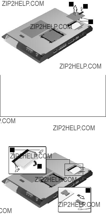
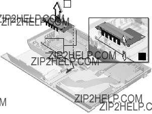
Modem Board Cover and Modem Board
1 3
2
Note: The screws do not separate from the modem boar cover.
To remove the modem board:
Disconnect the modem cable (4); then press the latches on both sides of the modem board (5), the modem board (6).
5
6
4
38 ThinkPad i Series 1400

Keyboard
?? ???Battery Assembly??? on page 36
2
1
Note: Be careful not to scratch the surface o plate cover.
3
ThinkPad i Series 391400
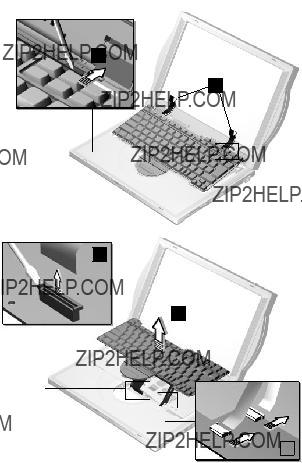
4
5
6
8
40 ThinkPad i Series 1400

2
1
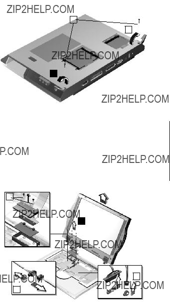
ThinkPad i Series 41400

?? ???Battery Assembly??? on page 36
?? ???Keyboard??? on page 39
?? ???CPU Thermal Plate??? on page 41
2
1
4
3
remove its polarized connector, disassemble it, h
above 100?? C (212??F), incinerate it, or expose i tents to water. Dispose of the battery as req ordiances or regulations. Use of an incorrect b result in ignition or explosion of the battery. batteries can be ordered from IBM or IBM auth dealers.
6
7
42 ThinkPad i Series 1400
Reverse the steps described above when install
hard disk drive.
ThinkPad i Series 431400

PCMCIA Holder
3
44 ThinkPad i Series 1400
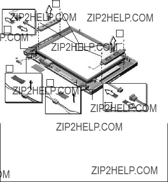
LCD Assembly
1
4
ThinkPad i Series 451400

46 ThinkPad i Series 1400
1
5
4
2
3
ThinkPad i Series 471400

6
48 ThinkPad i Series 1400

1
2
5
6
4
ThinkPad i Series 491400
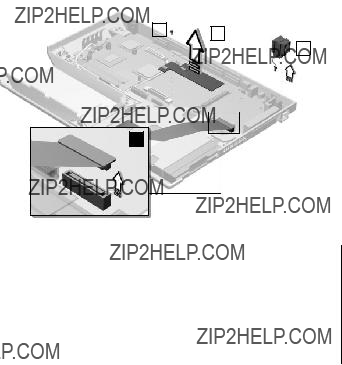
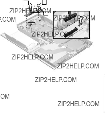
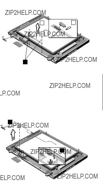
Trajection Board and Modem Connector
2
50 ThinkPad i Series 1400
DC/DC Charger
2
ThinkPad i Series 51400
52 ThinkPad i Series 1400
ThinkPad i Series 531400

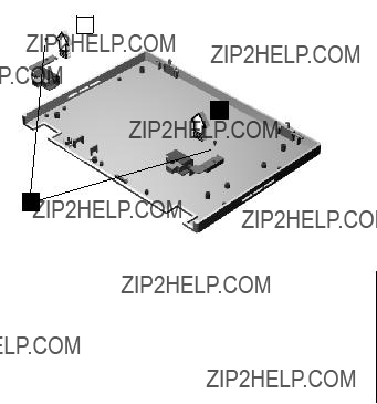
nector Board underneath the palm rest. You then
54 ThinkPad i Series 1400

ThinkPad i Series 551400

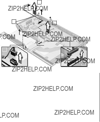
Fan Assembly
4
56 ThinkPad i Series 1400
Diskette and
Assembly
2
2
5
ThinkPad i Series 571400
the CD/DVD tray.
2
3
1
1
58 ThinkPad i Series 1400

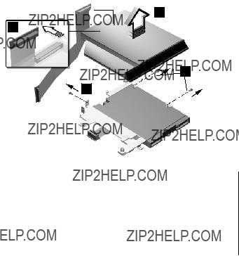
Diskette Drive (FDD with Bezel)
4
7
4
ThinkPad i Series 591400

60 ThinkPad i Series 1400

1
3
4
2
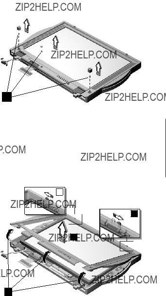
Note: When removing the LCD, take note of the following:
1. Be careful not to scratch the LCD co removing the screw covers.
ThinkPad i Series 61400
Speakers
Note: Make sure you use the correct screw for repla
Indicator Board and Microphone Cable
Assembly
62 ThinkPad i Series 1400
1
5
4
?????LCD Assembly??? on page 45
?????LCD Front Cover
ThinkPad i Series 631400

1
4
1
2
7
5
8
6
Attention: After you replace the LCD or inverter, instructions in ???Setting the LCD Panel ID??? on page
64 ThinkPad i Series 1400
Hinge
2
1
ThinkPad i Series 651400
1
3
4
2
Note: When removing the LCD, take note of the following:
1. Be careful not to scratch the LCD cove removing the screw covers.
66 ThinkPad i Series 1400
Speakers
Note: Make sure you use the correct screw for repl
Indicator Board and Microphone Cable
Assembly
?????LCD Front Cover
ThinkPad i Series 671400

1
5
4

1
2 4
3
5
Attention: After you replace the LCD or inverter, instructions in ???Setting the LCD Panel ID??? on page
ThinkPad i Series 691400
2
1
70 ThinkPad i Series 1400

Hinge
ThinkPad i Series 71400

Locations
Front View
1.LCD latches
2.LCD
3.Speakers
4.Indicator panel
8.Diskette drive
9.
10.Diskette eject button
11.
12.
13.
14.
15.
16.
17.
18.
19.
20.
21.
22.TrackPoint buttons
23.TrackPoint
72 ThinkPad i Series 1400

24.Fn key
25.
Bottom View
1.
2.Tilt feet
3.Memory slot door
Rear View
1. Power jack
2. Universal serial bus (USB) connector
3.
4.Serial connector
5.Parallel connector
6.Expansion connector
7. External monitor connector
8.Security keyhole
9.Power switch
10.
11.
12.
ThinkPad i Series 731400
13.Audio volume control
14.Battery pack
Switch Locations
Keyboard Language (SW3, Switch 1, 2 and
3)Setting
74 ThinkPad i Series 1400

System Unit Parts Listing
32
31
30
29
28
27
26
25
24
23
22
1
2
3
4
5
6
7
8
9
10
11
12
13
ThinkPad i Series 751400

76 ThinkPad i Series 1400
32KEYBOARD (ALPS ??? 1ST
SOURCE)
ThinkPad i Series 771400
78 ThinkPad i Series 1400

LCD Unit Parts Listing
12.1" LCD Unit Parts Listing
1
3
 2
2
8
ThinkPad i Series 791400
80 ThinkPad i Series 1400

14.1" LCD Unit Parts Listing
3
10
9
1
2
4
9
5
6
7
8
ThinkPad i Series 81400
82 ThinkPad i Series 1400

Miscellaneous Parts
ThinkPad i Series 831400

Telephone/Modem
84 ThinkPad i Series 1400

Power Cord
ThinkPad i Series 851400

Notices
References in this publication to IBM products, or services do not imply that IBM intends to mak
available in all countries in which IBM operates.
ence to an IBM product, program, or service is intended to state or imply that only IBM product or service may be used. Subject to IBM's valid property or other legally protectable rights, any equivalent product program, or service may be us
instead of the IBM product, program, or service
ation and verification of operation in conjunction
this document does not give you any license to
Trademarks
86 ThinkPad i Series 1400
IBM???
Part Number: 37L5192
Printed in U.S.A.