Implementing IBM
Tivoli Remote Control
Across Firewalls
Achieve Remote Control without sacrificing security
Guide for TCP/IP ports used and troubleshooting
Set up a secure Remote Control environment based on realistic scenarios
Edson Manoel
Francesca Balzi
Sebastien Fardel
Venkata R Reddy
ibm.com/redbooks
International Technical Support Organization
Implementing IBM Tivoli Remote Control Across
Firewalls
April 2003
Note: Before using this information and the product it supports, read the information in ???Notices??? on page xiii.
First Edition (April 2003)
This edition applies to the following products: IBM Tivoli Remote Control 3.8, IBM Tivoli Management Framework 4.1, and Tivoli Firewall Security Toolbox 1.3.
?? Copyright International Business Machines Corporation 2003. All rights reserved.
Note to U.S. Government Users Restricted Rights -- Use, duplication or disclosure restricted by GSA ADP Schedule Contract with IBM Corp.
iv IBM Tivoli Remote Control Across Firewalls
vi IBM Tivoli Remote Control Across Firewalls
viii IBM Tivoli Remote Control Across Firewalls
x IBM Tivoli Remote Control Across Firewalls
xii IBM Tivoli Remote Control Across Firewalls
Notices
This information was developed for products and services offered in the U.S.A.
IBM may not offer the products, services, or features discussed in this document in other countries. Consult your local IBM representative for information on the products and services currently available in your area. Any reference to an IBM product, program, or service is not intended to state or imply that only that IBM product, program, or service may be used. Any functionally equivalent product, program, or service that does not infringe any IBM intellectual property right may be used instead. However, it is the user's responsibility to evaluate and verify the operation of any non-IBM product, program, or service.
IBM may have patents or pending patent applications covering subject matter described in this document. The furnishing of this document does not give you any license to these patents. You can send license inquiries, in writing, to:
IBM Director of Licensing, IBM Corporation, North Castle Drive Armonk, NY 10504-1785 U.S.A.
The following paragraph does not apply to the United Kingdom or any other country where such provisions are inconsistent with local law: INTERNATIONAL BUSINESS MACHINES CORPORATION PROVIDES
THIS PUBLICATION "AS IS" WITHOUT WARRANTY OF ANY KIND, EITHER EXPRESS OR IMPLIED,
INCLUDING, BUT NOT LIMITED TO, THE IMPLIED WARRANTIES OF NON-INFRINGEMENT, MERCHANTABILITY OR FITNESS FOR A PARTICULAR PURPOSE. Some states do not allow disclaimer of express or implied warranties in certain transactions, therefore, this statement may not apply to you.
This information could include technical inaccuracies or typographical errors. Changes are periodically made to the information herein; these changes will be incorporated in new editions of the publication. IBM may make improvements and/or changes in the product(s) and/or the program(s) described in this publication at any time without notice.
Any references in this information to non-IBM Web sites are provided for convenience only and do not in any manner serve as an endorsement of those Web sites. The materials at those Web sites are not part of the materials for this IBM product and use of those Web sites is at your own risk.
IBM may use or distribute any of the information you supply in any way it believes appropriate without incurring any obligation to you.
Information concerning non-IBM products was obtained from the suppliers of those products, their published announcements or other publicly available sources. IBM has not tested those products and cannot confirm the accuracy of performance, compatibility or any other claims related to non-IBM products. Questions on the capabilities of non-IBM products should be addressed to the suppliers of those products.
This information contains examples of data and reports used in daily business operations. To illustrate them as completely as possible, the examples include the names of individuals, companies, brands, and products. All of these names are fictitious and any similarity to the names and addresses used by an actual business enterprise is entirely coincidental.
COPYRIGHT LICENSE:
This information contains sample application programs in source language, which illustrates programming techniques on various operating platforms. You may copy, modify, and distribute these sample programs in any form without payment to IBM, for the purposes of developing, using, marketing or distributing application programs conforming to the application programming interface for the operating platform for which the sample programs are written. These examples have not been thoroughly tested under all conditions. IBM, therefore, cannot guarantee or imply reliability, serviceability, or function of these programs. You may copy, modify, and distribute these sample programs in any form without payment to IBM for the purposes of developing, using, marketing, or distributing application programs conforming to IBM's application programming interfaces.

Trademarks
The following terms are trademarks of the International Business Machines Corporation in the United States, other countries, or both:
The following terms are trademarks of other companies:
ActionMedia, LANDesk, MMX, Pentium and ProShare are trademarks of Intel Corporation in the United States, other countries, or both.
Microsoft, Windows, Windows NT, and the Windows logo are trademarks of Microsoft Corporation in the United States, other countries, or both.
Java and all Java-based trademarks and logos are trademarks or registered trademarks of Sun Microsystems, Inc. in the United States, other countries, or both.
C-bus is a trademark of Corollary, Inc. in the United States, other countries, or both.
UNIX is a registered trademark of The Open Group in the United States and other countries.
SET, SET Secure Electronic Transaction, and the SET Logo are trademarks owned by SET Secure Electronic Transaction LLC.
Other company, product, and service names may be trademarks or service marks of others.
xiv IBM Tivoli Remote Control Across Firewalls
Preface
System administrators and help desk personnel sometimes need access to remote PCs in order to resolve problems and assist users with important business applications. Most organizations will, at some point, need to expand their management of systems from their regular systems management environment to those that exist on the other side of firewalls. Tivoli?? Remote Control allows a system administrator to control the keyboard and mouse input and monitor the display output of a remote machine, independently of the firewall architecture.
This book presents a concise documentation of known requirements for implementing the IBM Tivoli Remote Control 3.8 across firewalls.
This IBM?? Redbook will prove invaluable for Tivoli system administrators and Tivoli designers and firewall administrators planning, designing, implementing, and operating a Remote Control environment that involves firewalls. The results from a variety of test scenarios are presented along with tabulated firewall configuration requirements for the various components involved in such solution.
The team that wrote this redbook
This redbook was produced by a team of specialists from around the world working at the International Technical Support Organization, Austin Center.
Edson Manoel is a Software Engineer at the IBM Corporation, International Technical Support Organization (ITSO), Austin Center, working as an IT Specialist in the Systems Management area. Prior to joining the ITSO, Edson worked in the IBM Software Group as a Tivoli Technology Ambassador and in IBM Brasil Professional Services Organization as a Certified IT Specialist. He was involved in numerous projects, designing and implementing systems
management solutions for IBM customers and Business Partners. Edson holds a BSc degree in Applied Mathematics from Universidade de Sao Paulo, Brazil.
Francesca Balzi is a Tivoli Software Engineer at the IBM Tivoli Software Laboratory, in Italy. She has 7 years of experience in Customer Support. Her areas of expertise include problem determination and source identification in the client-server environment. She is currently performing Level 2 support for the EMEA Geo on IBM Tivoli Remote Control and IBM Tivoli Configuration Manager.
Sebastien Fardel is an Advisory IT Specialist at IBM Corporation, Global Services, Switzerland, acting as a Tivoli Architect in the Performance and Availability and Configurations and Operations areas. He has been in the IT industry since 1996 and has experience in IT infrastructure management, programming, and Systems Management area. His e-mail is sfa@ch.ibm.com.
Venkata Reddy is a software Engineer working for IBM Software Labs in Bangalore, India. He has three years of IT experience and is working as part of networking software group. He leads the firewall India team for providing Level3 support and Enhancements for IBM SecureWay?? firewall. His areas of expertise include network security and firewalls.
Thanks to the following people for their contributions to this project:
Joanne Luedtke, Lupe Brown, Wade Wallace, and Chris Blatchley
International Technical Support Organization, Austin Center
Yvonne Lyon
International Technical Support Organization, San Jose Center
Silvia Giacone, Nicola Milanese, and Ugo Madama
Remote Control Development and Verification Team, IBM Rome
Alan Hsu
Market Manager - Remote Control, IBM Software Group Austin
Become a published author
Join us for a two- to six-week residency program! Help write an IBM Redbook dealing with specific products or solutions, while getting hands-on experience with leading-edge technologies. You'll team with IBM technical professionals, Business Partners and/or customers.
Your efforts will help increase product acceptance and customer satisfaction. As a bonus, you'll develop a network of contacts in IBM development labs, and increase your productivity and marketability.
Find out more about the residency program, browse the residency index, and apply online at:
ibm.com/redbooks/residencies.html
xvi IBM Tivoli Remote Control Across Firewalls
Comments welcome
Your comments are important to us!
We want our Redbooks??? to be as helpful as possible. Send us your comments about this or other Redbooks in one of the following ways:
???Use the online Contact us review redbook form found at: ibm.com/redbooks
???Send your comments in an Internet note to: redbook@us.ibm.com
???Mail your comments to:
IBM Corporation, International Technical Support Organization
Dept. JN9B Building 003 Internal Zip 2834
11400 Burnet Road
Austin, Texas 78758-3493
xviii IBM Tivoli Remote Control Across Firewalls
Part 1
Part 1 Concepts and
planning
2 IBM Tivoli Remote Control Across Firewalls

1
Chapter 1. Remote Control sessions overview
System administrators often need to manage servers or workstations in distant secure locations ??? for example, in an outsourcing project. If a problem on one of these machines requires attention, the administrator traditionally has two options: try to resolve the problem over the telephone with an authorized person (with a high chance of miscommunication); or relocate to the user???s location for problem determination (which is often impractical). IBM Tivoli Remote Control allows an administrator to control the keyboard and mouse input and monitor the display output of a remote machine even in zones protected by any kind of network controlling process like firewalls. In addition, the administrator can just monitor, reboot the PC, or transfer files in a really simple way.
In this chapter we cover the following topics:
???Business perspectives for a solution using IBM Tivoli Remote Control across firewalls
???An overview of the IBM Tivoli Remote Control functionality
???A detailed description of the IBM Tivoli Remote Control components that will help to manage machines inside secure areas
???A detailed description of each type of communication used to exchange information between the different zones
1.1 IBM Tivoli Remote Control overview
The purpose of this chapter is not only to explain how IBM Tivoli Remote Control works in general, but to emphasize its architecture and functionality in a firewall environment. Even though the architecture and implementation of IBM Tivoli Remote Control may differ when firewalls are involved from implementation to implementation, the IBM Tivoli Remote Control functionality will remain the same. Therefore, in order to fully understand how remote control sessions work across firewalls, it is important to understand how this works in a non-secure environment.
IBM Tivoli Remote Control (ITRC) provides a complete real-time solution for remote controlling the target systems. For all intents and purposes, the technician or administrator???s keyboard and mouse become the primary keyboard and mouse for the target system for the duration of a remote control session. Functionalities such as chat, reboot, and file transfer are available to the administrator.
IBM Tivoli Remote Control runs on top of the IBM Tivoli Management Framework. However, in the context of a firewalls environment, some other components must be installed in order to simplify and secure the way that communications are exchanged between the different components of IBM Tivoli Remote Control. Before continuing and defining the complete Remote Control process across firewalls, it is important to first know and understand the utility and functionality of each component of IBM Tivoli Remote Control and of IBM Tivoli Management Framework.
1.1.1 IBM Tivoli Management Framework components
The IBM Tivoli Management Framework enables you to install and create several management components (services) that allow you to manage the resources in your network. You can install any or all of these services, depending on your organizational needs. As a minimum, one TMR server must be installed. The following is a list of the management services provided by the Tivoli Management Framework and a brief description of each:
4 IBM Tivoli Remote Control Across Firewalls
Managed Node A Tivoli Managed Node runs the same software that runs on a TMR Server. Managed Nodes maintain their own Object DataBases, which can be accessed by the TMR Server. When Managed Nodes communicate directly with other Managed Nodes, they perform the same communication or security operations as they would perform with the TMR Server. Although there is no clear distinction between managed systems and managing systems, the introduction of the Endpoints architecture leads to a paradigm shift. Managed Nodes are considered to be managing systems (hosting the desktop or running as a gateway), whereas endpoints are the managed systems.
Endpoint Manager The Endpoint Manager establishes and maintains the relationship between an Endpoint and its assigned Gateway. It is involved in taking the Endpoint in charge when its assigned Gateway is no longer responding. It is also involved in identifying the Gateways that an Endpoint is assigned to when applications are trying to contact the Endpoint. The Endpoint Manager runs on top of the TMR Server and is automatically created during the TMR Server installation process.
Endpoint Gateway The Endpoint Gateway provides access to the Endpoint methods and provides the communications with the TMR Server that the Endpoints occasionally require. A single Gateway can support communications with thousands of Endpoints and can launch methods on an Endpoint or run methods on the Endpoint???s behalf. A Gateway is created on an existing managed node.
Endpoint Proxy An Endpoint Proxy is an optional component that emulates Endpoints to the Gateway to simplify the Tivoli communications in a firewall environment through a common port. The Endpoint Proxy funnels requests for specific Endpoints through a single TCP/IP port and passes it down to a Relay or a Gateway Proxy. This component is part of the Tivoli Firewall Security Toolbox and must be installed on the same network zone as the Tivoli Endpoint Gateway on which it is connected.
Chapter 1. Remote Control sessions overview 5
6 IBM Tivoli Remote Control Across Firewalls
For more information about TMR Server, Managed Node, Endpoint Gateway, Endpoint and Policy Region, refer to Tivoli Management Framework Planning for Deployment Guide, GC32-0803.
For more information about Endpoint Proxy, Gateway Proxy and Relay, refer to Firewall Security Toolbox User ???s Guide, GC23-4826 and to Tivoli Enterprise Management Across Firewalls, SG24-5510.
1.1.2 IBM Tivoli Remote Control components
As already mentioned, the IBM Tivoli Remote Control is a client-server application that helps you take control over workstations on a network using a specific remote control technology. It could serve as a central location for monitoring and controlling machines at local or remote locations. The following is a definition list of the Remote Control components. Their installation is mandatory except for the Remote Control Proxies and the Remote Control Gateway, which are only used in environments where components of a Tivoli Management Region are separated by firewalls:
Chapter 1. Remote Control sessions overview 7
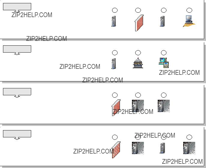
1.1.3 Tivoli components and communication symbols
In the figures and scenarios that follow, we use the following set of symbols to denote the various components and type of communication for easy recognition:
Tivoli Management Region Server (blue line)
Endpoint Gateway, Remote Control Server, Endpoint Manager or
Instance of the Tivoli Firewall Security Toolbox Relay
8 IBM Tivoli Remote Control Across Firewalls
Endpoint, Remote Control Controller or Remote Control Target
Policy Region (blue line)
Collection (blue line)
Remote Control Tool
Endpoint Proxy or Gateway Proxy (black line)
Remote Control Target Proxy or Remote Control Controller Proxy
Instance 1 of the Tivoli Firewall Security Toolbox Relay (black line)
Network zone secured by a firewall (red line)
Tivoli Framework communication (black line)
Tivoli Remote Control session communication (blue line)
Tivoli proprietary protocol encapsulated in HTTP (green line)
Chapter 1. Remote Control sessions overview 9
1.1.4 Parent-Child concept
The hierarchy of the components of either the Tivoli Firewall Security Toolbox or the Remote Control Proxies (either RC Target Proxy or RC Controller Proxy) is presented in terms of a Parent-Child relationship. Such hierarchy is a subset of the whole Tivoli Top-Down hierarchy. It means that the starting point is the TMR Server and the ending point is the Endpoint. The components close to the TMR Server will be Parents and the ones close to the Endpoints will be Children. However, some components could, at the same time, be a Child and a Parent, as they are just in between the Parent-Child hierarchy. You must also notice that a Parent could have more than one Child but that a Child could only have one Parent.
As the Endpoint Proxy, which simulates Endpoints, is the closest element from the TMR Server, it is a Parent and, as it is directly connected to a Tivoli Gateway, it could not have any Parent. As the Gateway Proxy, which simulates a Tivoli Gateway, is the closest element from the Endpoints, it is a Child and as it the most closest component from the bottom of the hierarchy, it could not have any Child. A Relay could be either a Parent or a Child. When it is connected to an Endpoint Proxy or to another Relay, it becomes a Child of those components. In another way, when a Gateway Proxy or another Relay connects to a Relay, this one also becomes a Parent for these components.
In the case of Remote Control Proxies being installed on top of the Tivoli Firewall Security Toolbox components, the RC Proxy (either Target or Controller Proxy) installed on the Endpoint Proxy is a Parent of Relays or other RC Proxies. The RC Proxy installed on the Gateway Proxy is a Child of an RC Proxy installed on an Endpoint Proxy or a Relay. As no Remote Control components could be installed on the Relay, an RC Proxy could only be either a Parent or a Child, but not both at the same time.
If the Remote Control Proxies are installed as Standalone components, you have to decide on the Parent-Child role for each of the Proxies (Target and Controller Proxies). For configuration improvement, it is advised to configure the Target Proxy as the Parent and the Controller Proxy as the Child. This is because connection requests to the Target Proxy are done by the RC Controller. So, this request is always forwarded by the RC Target Proxy to the RC Controller Proxy. In this case, to logically respect a Top-Down hierarchy and to improve performance for the request, the RC Target should be the Parent.
Figure 1-1 depicts the Top-Down Proxy hierarchy when Remote Control Proxy components are installed on top of the Tivoli Firewall Security Toolbox.
10 IBM Tivoli Remote Control Across Firewalls
Figure 1-1 Parent-Child hierarchy in RC Proxy-TFST architecture
Note: Understanding this hierarchy is important when you install and configure the components.
1.1.5 Proxy connection types
In some secure environments, the firewall???s constraints are so high that only communications from the more secure environment to the less secure environments are allowed. Either the Tivoli Firewall Security Toolbox or the Remote Control Proxies communications are designed to support those constraints. Even though we explain the proxy connection types in this section using the Tivoli Firewall Security Toolbox components, the same is valid for the Remote Control Proxies.
Different types of communications are available. The key point is which component initiates the communication:
Chapter 1. Remote Control sessions overview 11

???Bidirectional communication: In simple secure environments, communications could be initiated either by a component on the less secure zone or by the one located on the more secure zone. For example, an Endpoint initiates an upcall that is intercepted by the Gateway Proxy and further sent to the Endpoint Proxy, which in turn will forward it to the Tivoli Endpoint Gateway. In reverse, the Endpoint Proxy could initiate a downcall to the Endpoint without any restrictions.
???Unidirectional communication: In more secure environments, communications could only be initiated by components located in one of the zones. For example, if an Endpoint needs to initiate an upcall, this one is intercepted by the Gateway Proxy and held until the Endpoint Proxy polls their Gateway Proxies, at configurable intervals, to check if any of them have data to be sent. In this case, the Endpoint Gateway is called the Initiator, as it will be responsible to poll their Child. The Gateway Proxy is called the Listener, as it will wait for a send request before being able to transfer any information. The poll interval is set to 2 seconds by default and could be configured by changing the polling-interval parameter in the epproxy.cfg, gwproxy.cfg, and/or rcproxy.cfg configuration files. For more information about the Endpoint and Gateway proxies configuration files, refer to Firewall Security Toolbox User ???s Guide, GC23-4826. The IBM Tivoli Remote Control User???s Guide, SC23-4842, provides information for the Remote Control Proxies configuration files.
1.2IBM Tivoli Remote Control sessions overview
In this section we describe in detail the data flow of Remote Control sessions used in different implementations. This is meant to help you to fully understand how the communications of Remote Control work and what you have to consider in your design in order to respect the firewall restrictions.
The example scenarios used in this section are based on commonly found Remote Control architecture implementations in which the RC Controller is installed on the most secure side of the firewall and the Targets on the less secure zone. These scenarios should provide you enough information to master others more complicated situations. Furthermore, only the Remote Control action is discussed, but the process is basically the same for the File Transfer action. More information for these actions can be found in the IBM Tivoli Remote Control User???s Guide, SC23-4842.
Attention: Only the Remote Control and the File Transfer actions can use the Remote Control Proxy technology to cross firewalls.
12 IBM Tivoli Remote Control Across Firewalls

The Remote Control session scenarios could be divided into the following categories.
???Sessions in a single-TMR environment with no firewall restrictions. It is important to understand how these kinds of sessions work, because the basic concepts remain valid for all others scenarios.
???Sessions in a multi-TMR environment with no firewall restrictions. At first it seems similar to the way Remote Control works in a single-TMR environment. However, the HUB-Spoke concept introduces new constraints that need to be discussed. For more information about HUB-Spoke concept, refer to the Tivoli Management Framework Planning for Deployment Guide, GC32-0803.
???Sessions with firewall restrictions using the Remote Control Gateway component. We will describe how sessions are established for both single-TMR and multi-TMR environments when using the Remote Control Gateway component.
???Sessions with firewall restrictions using StandAlone Remote Control Proxies. We will show how sessions can be established for both single-TMR and multi-TMR environments when using the Remote Control Proxies. This type of sessions are commonly known as Remote Control Proxies in standalone mode.
???Sessions with firewall restrictions using the Remote Control Proxies in conjunction with the TFST components. We will show how sessions can be established for both single-TMR and multi-TMR environments, as well as for multi-firewall environments when using the Remote Control Proxies installed on top of the TFST components.
Note: There are three different ways to start a Remote Control session:
???Using the Tivoli Desktop
???Via the Tivoli WEB interface
???Using the Tivoli command line
In the following sections, only the Tivoli Desktop process will be discussed. However, the Remote Control data flow for any of the above methods remains the same. The advantage to use the Tivoli WEB interface is that even if you are on a secure site, the process will use the HTTP protocol, which is firewall friendly, to get the Targets list.
Nevertheless, as the following sections do not describe the best way to start a session, but only how the session works, for illustrative purposes only, we decided to use the Tivoli Desktop interface. For more information on how to start a Remote Control session, refer to the IBM Tivoli Remote Control User???s Guide, SC23-4842.
Chapter 1. Remote Control sessions overview 13
1.2.1 Session in a single-TMR environment
In order to fully understand how a Remote Control session works, it is important to know in detail the entire data flow between the different elements of IBM Tivoli Remote Control, starting with the most simple scenario.
Data flow for single-TMR session
Figure 1-2 shows in detail how a Remote Control session works in a single-TMR environment without firewall restrictions.
Figure 1-2 RC session data flow in a single-TMR environment
Based on Figure 1-2, here we provide a description of each step, from the time the Tivoli Administrator opens the Remote Control Tool (RC Tool) until the connection is established between the Controller and the Target.
The legend used in this diagram is explained as follows:
AThe Tivoli Administrator must first open an RC Tool to be able to select a Target from a list. As the RC Tool is located in a Policy Region, it needs to be opened as well.
14 IBM Tivoli Remote Control Across Firewalls
BAs soon as the RC Tool is opened, the Remote Control Server needs to validate the Controller by checking:
???If the Controller is an Endpoint
???If the label of the Endpoint is the same as of the hostname of the Controller
???If the interpreter of the Controller is supported and able to start a Remote Control session
In order to get this information, the Remote Control Server needs to contact the Endpoint Manager.
CIf the Controller is validated, the Remote Control Server loads a subset of the Remote Control policies from the Policy Region where the RC Tool is located. For our examples, we will call these basis policies. These basis policies are only accessed when the RC Tool is opened. No more are loaded for the time the Tool is active.
DAt this point, the Tivoli Administrator can start a Remote Control session by clicking the Run button of the RC Tool after selecting a Target.
EThe Remote Control Server needs to load the rest of the Remote Control policies. These policies are more network related and, for example, specifies if a Remote Control Proxy or a Remote Control Gateway should be used and which port are defined to start the session. Unlike the basis policies, these Remote Control policies are loaded every time a new session is started from this RC Tool. Example 1-1 shows which policies are read when the session starts, and which are read when the RC Tool is opened.
FAs soon as all Remote Control policies are loaded, the Remote Control Server needs to obtain additional information for both the Controller and the Target, such as their IP addresses. In order to get this information, the Remote Control Server must contact the Endpoint Manager.
GBefore initiating the connection, the Remote Control Server needs to know if the Target needs to be reached using an Endpoint Proxy/Gateway proxy infrastructure or not. If the Target is a proxied Endpoint, the Remote Control Server should send the request through an Endpoint Proxy instead of using the standard Tivoli Endpoint Gateway communication process.
HAs soon as the Remote Control Server knows how it should contact the Target, it sends the nd_start_target method down to the Target and waits for the process to start. The local process started on the Target machine is named EQNRCMAI.EXE.
Chapter 1. Remote Control sessions overview 15

IAs soon as the Target is started, the Remote Control Server sends the nd_start_controller method to the Controller and waits for the process to start. The local process started on the Controller machine is named EQNRSMAI.EXE.
JThe Remote Control session is now established. It is important to notice that once the session established, the Controller talks directly with the Target; this is a peer-to-peer communication. The Target is listening on port 2501 (port 2502 for File Transfer and port 2503 for chat) by default. On the Controller side, by default, the port is assigned by the communication stack. However, these ports could be easily changed by configuring the rc_def_ports Remote Control Policy.
Tracing for single-TMR session
Example 1-1 is a subset of the output from a IBM Tivoli Management Framework odstat command. It shows each method used to start a Remote Control session in a single-TMR environment as described above. This trace was captured from the time when a Tivoli Administrator opened an RC Tool until the session was established after the Administrator clicked the Run button of this RC Tool. This trace helps to fully depict the data flow shown in Figure 1-2 on page 14.
From the trace file, we can see what basis Remote Control policies are loaded when the Tivoli Administrator opens the RC Tool, and all the network related Remote Control policies that are loaded each time a Target request is started from a Controller. We can also see that the session is first started on the Target and then on the Controller before the peer-to-peer connection is established.
Example 1-1 RC session trace in a single-TMR environment
*******************************************************************************
Remote Control Tool is opened and RC Controller is checked.
*******************************************************************************
0.0.0 get_name_registry 1562174364.1.26 lookup
1562174364.1.1418#PcController::controller# _get_info 1562174364.1.26 lookup
1562174364.1.26 lookup 1562174364.1.4 lookup_id
1562174364.1.4##6@LCFData::ep_tnr_info_s describe 1562174364.1.26 lookup
1562174364.1.531#TMF_LCF::EpMgr# get_endpoint_key_value 1562174364.1.1413#PcRC::RemoteControl# get_policy_region 1562174364.1.1413#PcRC::RemoteControl# get_policy_region_name 1562174364.1.1413#PcRC::RemoteControl# _get_label
16 IBM Tivoli Remote Control Across Firewalls
*******************************************************************************
???Basis??? Remote Control Policies are loaded.
*******************************************************************************
1562174364.1.1127#TMF_PolicyRegion::GUI# rc_def_define 1562174364.1.1127#TMF_PolicyRegion::GUI# rc_def_uncheckedlist 0.0.0 get_name_registry
1562174364.1.26 lookup 1562174364.1.14#TMF_SysAdmin::Library# find_members 1562174364.1.184#TMF_SysAdmin::InstanceManager# find_members 1562174364.1.26 lookup
1562174364.1.4 lookup_id 1562174364.1.4##2@TMF_PolicyRegion::GUI describe 1562174364.1.4##2@TMF_PolicyRegion::GUI _get_type 1562174364.1.1139#TMF_PolicyRegion::GUI# find_members 0.0.0 get_name_registry
1562174364.1.26 lookup 1562174364.1.14#TMF_SysAdmin::Library# find_members 1562174364.1.184#TMF_SysAdmin::InstanceManager# find_members 1562174364.1.26 lookup
1562174364.1.4 lookup_id 1562174364.1.4##2@TMF_PolicyRegion::GUI describe 1562174364.1.4##2@TMF_PolicyRegion::GUI _get_type 1562174364.1.1141#TMF_PolicyRegion::GUI# find_members 1562174364.1.1413#PcRC::RemoteControl# _get_pres_object 1562174364.1.635#TMF_UI::Presentation# _get_dialogs 1562174364.1.635#TMF_UI::Presentation# _get_bitmaps 1562174364.1.1127#TMF_PolicyRegion::GUI# rc_def_command 1562174364.1.1127#TMF_PolicyRegion::GUI# rc_def_gw
1562174364.1.178#TMF_Administrator::Configuration_GUI# _get_label 1562174364.1.1127#TMF_PolicyRegion::GUI# rc_def_rcmode 1562174364.1.1127#TMF_PolicyRegion::GUI# rc_def_ftmode 1562174364.1.1127#TMF_PolicyRegion::GUI# rc_def_grace_time 1562174364.1.1127#TMF_PolicyRegion::GUI# rc_def_timeout_op 1562174364.1.1127#TMF_PolicyRegion::GUI# rc_def_optimize 1562174364.1.1127#TMF_PolicyRegion::GUI# rc_def_initstate 1562174364.1.1127#TMF_PolicyRegion::GUI# rc_def_alt_t 1562174364.1.1127#TMF_PolicyRegion::GUI# rc_def_backgrnd 1562174364.1.1127#TMF_PolicyRegion::GUI# rc_def_rate 1562174364.1.1127#TMF_PolicyRegion::GUI# rc_def_color 1562174364.1.1127#TMF_PolicyRegion::GUI# rc_def_inactivity 1562174364.1.1127#TMF_PolicyRegion::GUI# rc_def_gw 1562174364.1.1127#TMF_PolicyRegion::GUI# rc_def_comp
*******************************************************************************
Remote Control session is initiated by pressing the Run button of the RC Tool
*******************************************************************************
Chapter 1. Remote Control sessions overview 17

1562174364.1.1413#PcRC::RemoteControl# remote_control 1562174364.1.1127#TMF_PolicyRegion::GUI# rc_def_gw 1562174364.1.1127#TMF_PolicyRegion::GUI# rc_def_ports 1562174364.1.1127#TMF_PolicyRegion::GUI# rc_def_encryption 1562174364.1.1127#TMF_PolicyRegion::GUI# rc_def_proxy 1562174364.1.26 lookup
1562174364.1.531#TMF_LCF::EpMgr# get_endpoint_key_value 1562174364.21.517+#TMF_Endpoint::Endpoint# _get_label 1562174364.17.517+#TMF_Endpoint::Endpoint# _get_label 1562174364.1.26 lookup
1562174364.1.531#TMF_LCF::EpMgr# get_endpoint_key_value 1562174364.1.531#TMF_LCF::EpMgr# get_endpoint_key_value 1562174364.21.517+#TMF_Endpoint::Endpoint# is_proxied_ep 1562174364.21.517+#TMF_Endpoint::Endpoint# nd_start_target 1562174364.1.26 lookup
1562174364.1.531#TMF_LCF::EpMgr# get_endpoint_key_value 1562174364.17.517+#TMF_Endpoint::Endpoint# nd_start_controller 1562174364.1.26 lookup
1562174364.1.531#TMF_LCF::EpMgr# get_endpoint_key_value
In order to further explain the Remote Control session process, it is necessary to understand how the Remote Control Server knows which Controller the session is initiated from, and which Target the session should be started to. This information can be found in the IBM Tivoli Management Framework wtrace command output (wtrace -jHk $DBDIR). This trace was captured at the same time as the odstat command trace. The following examples show the detailed information from the wtrace output about the most important lines of the IBM Tivoli Management Framework odstat trace file shown in Example 1-1 on
page 16.
As a reference, the following information is important to understand the content of the examples:
???The object ID of the Target is 1562174364.21.517+#TMF_Endpoint::Endpoint#
???The object ID of the Controller is
1562174364.17.517+#TMF_Endpoint::Endpoint#
???The Object ID of the Remote Control Tool
1562174364.1.1413#PcRC::RemoteControl#
???The Tivoli Administrator who initiates this session is
Root_ITSO-region(ITSO\Administrator@ITSO)
Example 1-2 details the remote_control method which could also be named the Target request. It refers to the following line in Example 1-1 on page 16:
1562174364.1.1413#PcRC::RemoteControl# remote_control
18 IBM Tivoli Remote Control Across Firewalls

Example 1-2 The remote_control method from a single-TMR environment
{
1562174364:1,1562174364:1,220:135
}
#4
Input Data: (encoded):
{
251658240
[
"WD_DIALOG_OWNER=1562174364.1.1413#PcRC::RemoteControl#" "WD_GADGET_PATH=" "WD_SOURCE_PATH=btn_run" "WD_DIALOG_NAME =pcremote" "WD_DIALOG_INSTANCE=3668:0" "WD_DESKTOP_OID=1562 174364.1.549#TMF_UI::Extd_Desktop#" "WD_DESKTOP_PID=3436" "WD_DESKTOP_HOST=ITSO" "WD_DESKTOP_FQ_HOST=ITSO" "WD_DISPLAY =ITSO:0" "WD_OCO_OID=1562174364.1.178#TMF_Administrator: :Configuration_GUI#" "WD_VERSION=1" "WD_TYPE=Windows" "LANG=en" "LC_ALL=EN_US"
]
}
"1562174364.21.517+#TMF_Endpoint::Endpoint#" "1562174364.17.517 +#TMF_Endpoint::Endpoint#" 67109120 "controla" " /R50 /B /C8"
"""Root_ITSO-region(ITSO\Administrator@ITSO)
Example 1-3 details the is_proxied_ep method. It refers to the following line in Example 1-1 on page 16:
1562174364.21.517+#TMF_Endpoint::Endpoint# is_proxied_ep
This method checks if the Target is behind an Endpoint Proxy/Gateway Proxy architecture. If the result is true, Remote Control knows that an Endpoint Proxy must be used to contact the Target. We can see that the result of this method is false; this means that the Target is not an Endpoint connected to a Gateway Proxy.
Chapter 1. Remote Control sessions overview 19

Example 1-3 The is_proxied_ep method from a single-TMR environment
Results: (encoded):
false
Example 1-4 details the nd_start_target method. It refers to the following line in Example 1-1 on page 16:
1562174364.21.517+#TMF_Endpoint::Endpoint# nd_start_target
This method is used to start the local Remote Control process on the Target. The wtrace command output doesn???t show much information about this method in this type of architecture. However, it is important to know which method is used to start the session on the Target because, in some different situations, more information will be available for this method.
The return code of this method is 0; this means that the session starts without an error.
Example 1-4 The nd_start_target method from a single-TMR environment
Results: (encoded):
""0
Example 1-4 detailed the nd_start_controller method. The odstat line is:
1562174364.17.517+#TMF_Endpoint::Endpoint# nd_start_controller
This method is used to start the local Remote Control process on the Controller. The wtrace process doesn???t show much information about this method in this type of architecture. However, it is important to know which method is used to start the session on the Controller because, in some different situations, more information will be available for this method.
The return code of this method is 0; this means that the session starts without error.
Example 1-5 The nd_start_controller method from a single-TMR environment
Results: (encoded):
0
20 IBM Tivoli Remote Control Across Firewalls
1.2.2 Session in a multi-TMR environment
In order to continue to master the Remote Control session processes, it is also important to know in detail the whole data flow between the different elements of IBM Tivoli Remote Control in a multi-TMR environment. In a HUB-Spoke architecture, all managed resources should be placed in the Spoke TMR, and all profiles dedicated for the management should be created in the HUB TMR. As RC Tools are managed resources, we assume that they are created in the Spoke TMR. We also assume that the Targets are all managed by the Spoke TMR.
However, in order to let the Tivoli Administrator manage the Spoke TMR???s resources from the HUB TMR, the Controller has to be declared in the HUB TMR. This is because the resources of one Spoke TMR should never be able to directly access resources of another Spoke TMR; only the HUB TMR resources could manage all others. Furthermore, some resources, such as Endpoints, Policy Region, and RemoteControl, need to be exchanged between the HUB and Spoke TMRs. For more information about resources exchange between TMRs, refer to the Tivoli Management Framework Planning for Deployment Guide, GC32-0803.
Data flow for a multi-TMR session
Figure 1-3 shows in detail how a Remote Control session is working in a
HUB-Spoke TMR environment without firewall restrictions.
Chapter 1. Remote Control sessions overview 21
Figure 1-3 RC session data flow in a multi-TMR environment
Based on Figure 1-3, here we detail each step from the time when the Tivoli Administrator opens an RC Tool from a Collection located in the HUB TMR until the connection is established between the Controller and the Target.
The legend used in Figure 1-3 is explained as follows:
AThe Tivoli Administrator must first open an RC Tool to be able to select a Target from a list. As the RC Tool is located in a Policy Region of the Spoke TMR, a Collection containing the Spoke RC Tool is available in the HUB TMR.
BAs soon as the RC Tool on the Spoke is opened, the Spoke Remote Control Server needs to validate the Controller by checking:
???If the Controller is an Endpoint.
22 IBM Tivoli Remote Control Across Firewalls
???If the label of the Endpoint is the same as of the hostname of the Controller
???If the interpreter of the Controller is supported and able to start a Remote Control session.
In order to get this information, the Spoke Remote Control Server needs to contact the Spoke Endpoint Manager.
CAs the Controller is not an Endpoint of the Spoke TMR, thus not known by the Spoke Endpoint Manager, the Spoke Endpoint Manager must get the Region ID from the Controller Object ID and must find a way to contact the Endpoint Manager of this other TMR known by the Region ID. As soon as the Spoke Endpoint Manager find the way to contact the HUB Endpoint Manager, it transfers the request it receives from the Spoke Remote Control Server and waits for the return.
DIf the Controller, based on the information received from the HUB Endpoint Manager, is authorized to be a Controller, the Spoke Remote Control server loads a subset of the Remote Control policies. For our examples, we will call these policies basis policies. These policies are not loaded not from the Spoke RC Tool but from the Spoke Policy Region where the Tool is located. These basis policies are only accessed when the RC Tool is opened and no more loaded for the time the Tool is active.
EAt this point, the Tivoli Administrator could decide to start a session by clicking the Run button of the Spoke Remote Control Tool after selecting a Target.
FThe Spoke Remote Control Server needs to load the rest of the Remote Control policies. These policies are more network related and, for example, specify if a Remote Control Proxy or a Remote Control Gateway should be used and which ports are defined to start the session. Unlike the basis policies, these Remote Control policies are loaded every time a new session is started from this Spoke RC Tool. Example 1-7 on page 25 shows which policies are read when the session starts and which are read when the RC Tool is opened.
GAs soon as all Remote Control policies are loaded, the Spoke Remote Control Server needs to obtain additional information for both the Controller and the Target, such as their IP addresses. In order to get this information, the Remote Control Server must contact the Spoke Endpoint Manager.
Chapter 1. Remote Control sessions overview 23
HThe Spoke Endpoint Manager is able to provide information for the Target machine as this Endpoint is part of the same TMR. However, for the Controller, once again, it could not find any information for it inside its Endpoint Database. The Spoke Endpoint Manager needs to extract the Region ID of the Controller Object ID and must find a way to contact the HUB Endpoint Manager. As soon the Spoke Endpoint Manager find the way to contact the HUB Endpoint Manager, it transfers the request it receives from the Spoke Remote Control Server and waits for the return.
IBefore initiating the connection, the Spoke Remote Control Server needs to know if the Target needs to be reached using an Endpoint Proxy/Gateway proxy infrastructure or not. If the Target is a proxied Endpoint, the Spoke Remote Control Server should send the request through an Endpoint Proxy instead of using the standard Tivoli Endpoint Gateway communication process.
JAs soon as the Spoke Remote Control Server knows how to contact the Target, it sends the nd_start_target method down to the Target and waits for the process to starts. The local process started on the machine is named EQNRCMAI.EXE.
KAs soon as the Target is started, the Spoke Remote Control Server sends an nd_start_controller method to the Controller, but as it knows that the Controller is not part of the Spoke TMR, it forwards the request to the HUB TMR. The HUB Remote Control Server is sending the nd_start_controller method to the Controller and waits for the process to start. The local process started on the machine is named EQNRSMAI.EXE.
LThe Remote Control session is now established. Notice that once the session established, the Controller talks directly with the Target; this is a peer-to-peer communication. The Target is listening on port 2501 (port 2502 for File Transfer and port 2503 for chat) by default. On the Controller side, by default, the port is assigned by the communication stack. However, these ports could be easily changed by configuring the rc_def_ports Remote Control Policy.
Tracing for a multi-TMR session
Example 1-6 and Example 1-7 show subsets of IBM Tivoli Management Framework odstat command output from the HUB TMR and the Spoke TMR respectively. They show each method used to start a Remote Control session in a multi-TMR environment described above. This trace was captured from the time the Tivoli Administrator opened an RC Tool until the session was established after the Administrator clicked the Run button of this RC Tool. This trace helps to fully depict the data flow that was shown in Figure 1-3 on page 22.
24 IBM Tivoli Remote Control Across Firewalls

From Example 1-7, we could analyze that all methods needed to get information from the HUB TMR are initiated on the Spoke TMR. Furthermore, all of these methods will be found again in the HUB TMR trace file. Even if these methods are initiated by the Spoke TMR, they are nevertheless managed by the HUB TMR. In the Spoke TMR trace file (Example 1-7), we could also see that all basis Remote Control policies are loaded when the Tivoli Administrator opens the RC Tool, and that all network related Remote Control policies are loaded each time a Target request is started from a Controller. In addition to that, we could also remark that the session is first started on the Target and then on the Controller before the peer-to-peer connection between them is established.
In order to understand the information shown in the trace files, the Region IDs of the HUB and Spoke TMRs in our environment are:
???HUB TMR: 1380596993
???Spoke TMR: 1519322503
Example 1-6 is the trace file from the HUB TMR Server.
Example 1-6 RC session trace from the HUB TMR in a multi-TMR environment
1380596993.1.536#TMF_LCF::EpMgr# get_endpoint_key_value 1380596993.1.536#TMF_LCF::EpMgr# get_endpoint_key_value 1380596993.1.179#TMF_Administrator::Configuration_GUI# _get_label 1380596993.1.631#TMF_UI::Extd_Desktop# connect 1380596993.7.522+#TMF_Endpoint::Endpoint# _get_label 1380596993.1.536#TMF_LCF::EpMgr# get_endpoint_key_value
1380596993.7.522+#TMF_Endpoint::Endpoint# nd_start_controller
1380596993.1.536#TMF_LCF::EpMgr# get_endpoint_key_value
Example 1-7 is the trace file from the Spoke TMR Server.
Example 1-7 RC session trace from the Spoke TMR in a multi-TMR environment
*******************************************************************************
Remote Control Tool is opened and RC Controller is checked.
*******************************************************************************
0.0.0 get_name_registry 1519322503.1.26 lookup 1519322503.1.26 lookup 1519322503.1.26 lookup 1519322503.1.26 lookup 1519322503.1.26 lookup 1519322503.1.4 lookup_id
1519322503.1.4##6@LCFData::ep_tnr_info_s describe 1519322503.1.26 lookup
1519322503.1.536#TMF_LCF::EpMgr# get_endpoint_key_value
Chapter 1. Remote Control sessions overview 25
1380596993.1.536#TMF_LCF::EpMgr# get_endpoint_key_value
1519322503.1.26 lookup
1519322503.1.536#TMF_LCF::EpMgr# get_endpoint_key_value
1380596993.1.536#TMF_LCF::EpMgr# get_endpoint_key_value
1519322503.1.707#PcRC::RemoteControl# get_policy_region 1519322503.1.707#PcRC::RemoteControl# get_policy_region_name 1519322503.1.707#PcRC::RemoteControl# _get_label
*******************************************************************************
???Basis??? Remote Control Policies are loaded.
*******************************************************************************
1519322503.1.705#TMF_PolicyRegion::GUI# rc_def_define 1519322503.1.705#TMF_PolicyRegion::GUI# rc_def_uncheckedlist 0.0.0 get_name_registry
1519322503.1.26 lookup 1519322503.1.14#TMF_SysAdmin::Library# lookup_object
1519322503.1.521#TMF_SysAdmin::InstanceManager# get_instances_interface 1519322503.1.14#TMF_SysAdmin::Library# select_instance_managers 1519322503.1.26 get_all
1519322503.1.26 lookup 1519322503.1.4 lookup_id
1519322503.1.4##6@LCFData::ep_tnr_info_s describe
1519322503.1.707#PcRC::RemoteControl# _get_pres_object
1519322503.1.679#TMF_UI::Presentation# _get_dialogs 1519322503.1.679#TMF_UI::Presentation# _get_bitmaps
1519322503.1.705#TMF_PolicyRegion::GUI# rc_def_command 1519322503.1.705#TMF_PolicyRegion::GUI# rc_def_gw 1380596993.1.179#TMF_Administrator::Configuration_GUI# _get_label
1519322503.1.705#TMF_PolicyRegion::GUI# rc_def_rcmode 1519322503.1.705#TMF_PolicyRegion::GUI# rc_def_ftmode 1519322503.1.705#TMF_PolicyRegion::GUI# rc_def_grace_time 1519322503.1.705#TMF_PolicyRegion::GUI# rc_def_timeout_op 1519322503.1.705#TMF_PolicyRegion::GUI# rc_def_optimize 1519322503.1.705#TMF_PolicyRegion::GUI# rc_def_initstate 1519322503.1.705#TMF_PolicyRegion::GUI# rc_def_alt_t 1519322503.1.705#TMF_PolicyRegion::GUI# rc_def_backgrnd 1519322503.1.705#TMF_PolicyRegion::GUI# rc_def_rate 1519322503.1.705#TMF_PolicyRegion::GUI# rc_def_color 1519322503.1.705#TMF_PolicyRegion::GUI# rc_def_inactivity 1519322503.1.705#TMF_PolicyRegion::GUI# rc_def_gw 1519322503.1.705#TMF_PolicyRegion::GUI# rc_def_comp 1380596993.1.631#TMF_UI::Extd_Desktop# connect
1519322503.1.26 lookup
*******************************************************************************
Remote Control session is initiated by pressing the Run button of the RC Tool
*******************************************************************************
26 IBM Tivoli Remote Control Across Firewalls

1519322503.1.707#PcRC::RemoteControl# remote_control 1519322503.1.705#TMF_PolicyRegion::GUI# rc_def_gw 1519322503.1.705#TMF_PolicyRegion::GUI# rc_def_ports 1519322503.1.705#TMF_PolicyRegion::GUI# rc_def_encryption 1519322503.1.705#TMF_PolicyRegion::GUI# rc_def_proxy 1519322503.1.26 lookup
1519322503.1.536#TMF_LCF::EpMgr# get_endpoint_key_value 1519322503.18.522+#TMF_Endpoint::Endpoint# _get_label
1380596993.7.522+#TMF_Endpoint::Endpoint# _get_label
1519322503.1.26 lookup
1519322503.1.536#TMF_LCF::EpMgr# get_endpoint_key_value 1519322503.1.536#TMF_LCF::EpMgr# get_endpoint_key_value 1519322503.18.522+#TMF_Endpoint::Endpoint# is_proxied_ep 1519322503.18.522+#TMF_Endpoint::Endpoint# nd_start_target 1519322503.1.26 lookup
1519322503.1.536#TMF_LCF::EpMgr# get_endpoint_key_value
1380596993.1.536#TMF_LCF::EpMgr# get_endpoint_key_value 1380596993.7.522+#TMF_Endpoint::Endpoint# nd_start_controller
1519322503.1.26 lookup
1519322503.1.536#TMF_LCF::EpMgr# get_endpoint_key_value 1380596993.1.536#TMF_LCF::EpMgr# get_endpoint_key_value 1519322503.1.26 lookup 1519322503.1.88#TMF_SysAdmin::InstanceManager# connect
In order to explain how the Spoke Remote Control Server knows which Controller the session is initiated from and which Target the session should be started to, we need to analyze the output of the wtrace command from the Spoke TMR Server. This trace was captured at the same time as the odstat command trace.
The following examples will show the detailed information from the wtrace command output about the most important lines of the IBM Tivoli Management Framework odstat trace file shown in Example 1-6 on page 25 and in Example 1-7 on page 25.
As a reference, the following information is important to understand the content of the examples:
???The Object ID of the Target is
1519322503.18.522+#TMF_Endpoint::Endpoint#
???The Object ID of the Controller is
1380596993.7.522+#TMF_Endpoint::Endpoint#
???The Object ID of the RC Tool is 1519322503.1.707#PcRC::RemoteControl#
???The Tivoli Administrator who initiates the section is root@lpar07.itsc.austin.ibm.com
Chapter 1. Remote Control sessions overview 27

Example 1-8 details the remote_control method started from the Spoke TMR Server which could also be named the Target request. It refers to the following line in Example 1-7 on page 25:
1519322503.1.707#PcRC::RemoteControl# remote_control
Example 1-8 The remote_control method from a Spoke TMR
1519322503:1,1519322503:1,7:1207
}
#4
Input Data: (encoded):
{
14
[
"WD_DIALOG_OWNER=1519322503.1.707#PcRC::RemoteControl#" "WD_GADGET_PATH=" "WD_SOURCE_PATH=btn_run" "WD_DIALOG_NAME =pcremote" "WD_DIALOG_INSTANCE=30278:0" "WD_DESKTOP_OID=138 0596993.1.631#TMF_UI::Extd_Desktop#" "WD_DESKTOP_PID=1360" "WD_DESKTOP_HOST=TIC01008" "WD_DESKTOP_FQ_HOST=TIC01008" "WD_DISPLAY=TIC01008:0" "WD_OCO_OID=1380596993.1.179#TMF_A dministrator::Configuration_GUI#" "WD_VERSION=1" "WD_TYPE=Wi ndows" "LANG=en"
]
}
"1519322503.18.522+#TMF_Endpoint::Endpoint#" "1380596993.7.522+ #TMF_Endpoint::Endpoint#" 65540 "controla" " /R50 /B /C8" "" "Root_tic01010-region(root@lpar07.itsc.austin.ibm.com)"
Example 1-9 details the is_proxied_ep method started from the Spoke TMR Server. It refers to the following line in Example 1-7 on page 25:
1519322503.18.522+#TMF_Endpoint::Endpoint# is_proxied_ep
This method checks if the Target is behind an Endpoint Proxy/Gateway Proxy architecture. If the result is true, Remote Control knows that an Endpoint Proxy must be used to contact the Target. We see that the result of this method is false; this means that the Target is not an Endpoint connected to a Gateway Proxy.
28 IBM Tivoli Remote Control Across Firewalls

Example 1-9 The is_proxied_ep method from a Spoke TMR
Results: (encoded):
false
Example 1-10 details the nd_start_target method started from the Spoke TMR Server. It refers to the following line in Example 1-7 on page 25:
1519322503.18.522+#TMF_Endpoint::Endpoint# nd_start_target
This method is used to start the local Remote Control process on the Target. The return code of this method is 0; this means that the session starts without error.
Example 1-10 The nd_start_target method from a Spoke TMR
Example 1-11 details the nd_start_controller method started from the Spoke TMR Server. It refers to the following line in Example 1-7 on page 25:
1380596993.7.522+#TMF_Endpoint::Endpoint# nd_start_controller
This method is used to start the local Remote Control process on the Controller. However, this method is first started from the Spoke TMR, and as the Endpoint Manager of this TMR doesn???t know the Controller Endpoint, the method must be transferred to the HUB TMR with all needed information.
As a reference, the Target IP address is 9.3.4.247 and the Controller IP address is 9.3.4.244.
The return code of this method is 0; this means that the session starts without error.
Example 1-11 The nd_start_controller method from a Spoke TMR
Object ID: 1380596993.7.522+#TMF_Endpoint::Endpoint# Method: nd_start_controller
Principal: root@lpar07.itsc.austin.ibm.com (0/0) Path:
Input Data: (encoded): "\tivoli\pcremote\eqnrsmai.exe"
{
1
Chapter 1. Remote Control sessions overview 29
[
"/I9.3.4.247 /
],
,((!?+;
]
/Ntic01006 /
],
,((!?+;
]
/B18 /A /T /
]
;+?!((,,
]
/HRoot_tic01010-region(root@lpar07.itsc.austin.ibm.com) /
]
;+?!((,,
]
"
Example 1-12 details the nd_start_controller method started from the HUB TMR Server. It refers to the following line in Example 1-6 on page 25:
1380596993.7.522+#TMF_Endpoint::Endpoint# nd_start_controller
As soon as the Spoke TMR asked the HUB TMR Server to start the Controller, the same nd_start_controller method is started on the HUB TMR Server. The return code of this method is 0; this means that the session starts without error.
Example 1-12 The nd_start_controller method from a HUB TMR
0
30 IBM Tivoli Remote Control Across Firewalls
1.2.3 Session using a Remote Control Gateway
In the following sections we describe how Remote Control sessions are established in a firewall environment using the Remote Control Gateway component for both single-TMR and multi-TMR environments. As this technology had been previously developed to allow Remote Control sessions in a firewall environment before the Remote Control Proxy technology was announced, we won???t go into details on this process, and no trace will be discussed. Nevertheless, it could be interesting to have an idea of how it works to compare and understand the two different technologies.
The Remote Control Gateway must be installed on top of a Tivoli Endpoint Gateway. If you match the Remote Control Gateway port to your firewall configurations, you enable all Controllers to access all the Targets that reside on the other side of the firewall, through the same Remote Control Gateway. Furthermore, the Remote Control Gateway can???t be used to bridge two different LAN.
Data flow for RC Gateway/single-TMR session
Figure 1-4 shows in detail how a Remote Control session works using a Remote Control Gateway in a single-TMR environment with firewall restrictions.
Chapter 1. Remote Control sessions overview 31
Figure 1-4 RC session data flow in an RC Gateway/single-TMR environment
Based on Figure 1-4, here we detail each step from the time the Tivoli Administrator opens a Remote Control Tool until the connection is established between the Controller and the Target.
The legend used in Figure 1-4 is explained as follows:
Steps A, B,C, D, E, F, G, H and I remain the same as for a Remote Control session in single-TMR environment without firewall restriction. Refer to ???Data flow for single-TMR session??? on page 14 for detailed information about these steps.
The remaining step is different and is defined as follows:
JThe rc_def_gw policy has been configured to force the usage of the Remote Control Gateway, and the Remote Control Server has been informed of that on step E. The Remote Control server then has
32 IBM Tivoli Remote Control Across Firewalls

informed the Controller (step I) to use the Remote Control Gateway in order to contact the Target. As the Controller knows on which Managed Node the Remote Control Gateway is installed and which port has to be used, it starts to communicate with the Target using this specific network path. The Remote Control session is now established. It is important to notice that once the session established, the Controller talks directly with the Target, but it???s not a peer-to-peer communication (Controller-Target) anymore, as the communication flow must always go through the Remote Control Gateway. The Target is listening on the port defined in the rc_def_gw policy. If 0 is specified as the parameter, the port is assigned by the communication stack. On the Controller side, by default, the port is assigned by the communication stack. However, this port could be easily fixed by configuring the rc_def_ports Remote Control Policy.
In order to force the Remote Control session to use a Remote Control Gateway, the rc_def_gw default policy method needs to be configured as shown in Example 1-13.
Example 1-13 The rc_def_gw default policy method for Remote Control
#!/bin/sh
#
#Default policy method for Remote Control gateway
#This policy method determines whether or not to
#use the Remote Control gateway.
#
#Possible values:
#YES <ManagedNode-label> <GatewayPort> <MaxSessions> IP:<IP-Port>
#Use the specified Remote Control gateway,
#where:
#<ManagedNode-label> is the name of the managed node
#to be used as Remote Control gateway.
#<GatewayPort> is the TCP/IP port used by the Remote
#Control gateway to listen for connection request from
#controllers.
#<MaxSessions> is the number of Tivoli Remote Control
#sessions between a controller and target that the Remote
#Control gateway can handle on the same incoming port.
#The maximum value is 64.
#<IP-Port> is the local TCP/IP port used by the Remote
#Control gateway to communicate with TCP/IP targets.
#If it has the value 0, the Remote Control gateway uses
#a port generated by the communication stack.
#
# Default value: NO
Chapter 1. Remote Control sessions overview 33
echo "YES tic01002 8877 64 IP:0"
exit 0
Data flow for an RC Gateway/multi-TMR session
Figure 1-5 shows in detail how a Remote Control session works using a Remote Control Gateway in a multi-TMR environment with firewall restrictions.
Figure 1-5 RC session data flow in an RC Gateway/multi-TMR environment
Based on Figure 1-5, here we detail each step from the time when the Tivoli Administrator opens a Remote Control Tool until the connection is established between the Controller and the Target.
34 IBM Tivoli Remote Control Across Firewalls
The legend used in Figure 1-5 is explained as follows:
Steps A, B,C, D, E, F, G, H, I, J, and K remain the same as for a Remote Control session in a multi-TMR environment without the firewall restriction. Refer to ???Data flow for a multi-TMR session??? on page 21 for detailed information about these steps.
The remaining step is different and is defined as follows:
LThe rc_def_gw policy has been configured to force the usage of the Remote Control Gateway and the Remote Control Server has been informed of that on step F. The Remote Control server then has informed the Controller (step K) to use the Remote Control Gateway in order to contact the Target. As the Controller knows on which Managed Node the Remote Control Gateway is installed and which port has to be used, it could start to communicate with the Target using this specific network path. The Remote Control session is now established. It is important to notice that once the session established, the Controller talks directly with the Target, but it???s not a peer-to-peer communication (Controller-Target) anymore, as the communication flow must always go through the Remote Control Gateway. The Target is listening on port defined in the rc_def_gw policy. If 0 is specified as parameter, the port is assigned by the communication stack. On the Controller side, by default, the port is assigned by the communication stack. However, this port could be easily fixed by configuring the rc_def_ports Remote Control Policy.
In order to force the Remote Control session to use a Remote Control Gateway, the rc_def_gw default policy method needs to be configured as shown in Example 1-13 on page 33. This has to be done in the Spoke TMR where the Remote Control Object is located.
1.2.4 Session using Remote Control Proxies Standalone
In the following sections we describe the Remote Control Proxy Standalone architecture for both single-TMR and multi-TMR environments.
The Remote Control Proxy components enable machines on a side of a firewall to communicate, through a common definable port, to machines on the other side of the firewall. Thus, the Controller is able to start a session with a Target by minimizing the impact on the security infrastructure.
However, the Remote Control Proxy Standalone solution could only be used if a standard Tivoli Endpoint Gateway is installed in the same network zone as the Targets. Otherwise, the Remote Control Proxy on top of the Tivoli Firewall Security Toolbox solution needs to be deployed.
Chapter 1. Remote Control sessions overview 35
The RC Target Proxy emulates the Target located in another network zone to the Controller. The Target Proxy must be able to communicate with the Controller without any firewall constraints, and thus must be located in the same network zone as the Controller.
On the other side, the RC Controller Proxy emulates the Controller located in another zone to the Target. The Controller Proxy must be able to communicate with the Target without any firewall constraints, and thus must be located in the same network zone as the Target.
Data flow for RC Proxy Standalone/single-TMR session
Figure 1-6 shows in detail how a Remote Control session works using a Remote Control Proxy Standalone architecture in a single-TMR environment with firewall restrictions.
Figure 1-6 RC session data flow in an RC Proxy Standalone/single-TMR
36 IBM Tivoli Remote Control Across Firewalls
Based on Figure 1-6, here we detail each step from the time the Tivoli Administrator opens a Remote Control Tool until the connection is established between the Controller and the Target using the Remote Control Proxies.
The legend used in Figure 1-6 is explained as follows:
Steps A, B,C, D, E, F, G, H and I are similar to a Remote Control session in single-TMR environment without firewall restriction. Refer to ???Data flow for single-TMR session??? on page 14 for detailed information about these steps.
The remaining step is different and defined as follows:
JBoth sessions on the Target and on the Controller are now started. At this step, the Controller needs to establish the link to control the Target. The rc_def_proxy policy has been configured to force the usage of the Remote Control Proxies and the Remote Control Server has been informed of that on step E. The Remote Control server then has informed the Controller (step I) to use the RC Target Proxy in order to contact the Target. The Controller is able now to transfer the connection request to the RC Target Proxy as it got its IP address.
When the RC Target Proxy receives the request containing the IP address of the requested Target, it can start searching in the rcproxy.route file for the RC Controller Proxy the Target is connected to. In fact, this file contains a list of all distant Endpoints and their assigned RC Controller Proxy and needs to be manually customized. For more information about how to configure this file, refer to 3.3.2, ???Remote Control Proxy configuration??? on page 104. The RC Target Proxy then contacts the correspondent RC Controller Proxy to forward the Target connection request. The RC Controller Proxy uses the Target information stored in the first request to start a session with the Target.
The Remote Control session is now established. It is important to notice that once the session established, the Controller talks directly with the Target, but it???s not a peer-to-peer communication (Controller-Target) anymore, as the communication flow must always go through the Remote Control Proxies.
The Target is listening on port defined in the rc_def_ports policy. On the Controller side, by default, the port is assigned by the communication stack. However, these ports could be easily changed by configuring the rc_def_ports Remote Control Policies. The RC Target Proxy and the RC Controller Proxy are listening on the port defined during the installation process. The port specified in the rc_def_proxy policy must be the same as defined during the installation process of the RC Target Proxy. The configuration of these RC Proxies ports could be reviewed by editing the rcproxy.cfg
Chapter 1. Remote Control sessions overview 37

configuration file. However, if you decided to change this port, you need to also review the rc_def_proxy policy. For more information about the RC Proxies configuration files, refer to IBM Tivoli Remote Control User???s Guide, SC23-4842.
Sometimes, the Controller could be in a secure zone and managed by a local Tivoli Endpoint Gateway and the Target could be in another secure zone and also be managed by a local Tivoli Endpoint Gateway. In this case, two firewalls separate the Controller and its RC Target Proxy from the Target and its RC Controller Proxy. The TFST Relay could be installed in the zone between the two secure zones and used to pass the information between the RC Target Proxy and the RC Controller Proxy.
In order to implement the Remote Control session to use Remote Control Proxies, the rc_def_proxy default policy method needs to be configured as shown in Example 1-14.
Example 1-14 The rc_def_proxy default policy method for Remote Control
#!/bin/sh
#
#Default policy method for Remote Control Proxy
#This policy method determines whether to use Remote Control Proxies.
#If you use Remote Control Proxies, rc_def_proxy defines how the controller
#uses the Remote Control Proxies to start a session with a target across a
#firewall.
#YES <configuration type> <rc proxy ip address> <rc proxy port>
#Use the Remote Control Proxies, where:
#
#<configuration type>
38 IBM Tivoli Remote Control Across Firewalls
#<rc proxy ip address>
#<rc proxy port>
#Default value: NO
#Examples follow.
#First example:
#YES manual 192.168.100.50 3501
#Second example:
#YES auto 3501
#
#Third example:
#NO
#
echo "YES manual 9.3.4.169 8888"
exit 0
Data flow for an RC Proxy Standalone/multi-TMR session
Figure 1-7 shows in detail how a Remote Control session works using a Remote Control Proxy Standalone architecture in a multi-TMR environment with firewall restrictions.
Chapter 1. Remote Control sessions overview 39
Figure 1-7 RC session data flow in an RC Proxy Standalone/multi-TMR
Based on Figure 1-7, here we detail each step from the time the Tivoli Administrator opens a Remote Control Tool until the connection is established between the Controller and the Target using the Remote Control Proxies.
The legend used in Figure 1-7 is explained as follows:
Steps A, B,C, D, E, F, G, H, I, J and K are similar to a Remote Control session in multi-TMR environment without firewall restriction. Refer to ???Data flow for a multi-TMR session??? on page 21 for detailed information about these steps.
The remaining step is different and defined as follows:
LBoth sessions on the Target and on the Controller are now started. At this step, the Controller need to establish the link to control the Target. The rc_def_proxy policy has been configured to force the usage of the Remote Control Proxies and the Remote Control Server
40 IBM Tivoli Remote Control Across Firewalls
has been informed of that on step F. The Remote Control server then has informed the Controller (step K) to use the RC Target Proxy in order to contact the Target. The Controller is able now to transfer the connection request to the RC Target Proxy as it got its IP address.
When the RC Target Proxy receives the request containing the IP address of the requested Target, it can start searching in the rcproxy.route file for the RC Controller Proxy the Target is connected to. In fact, this file contains a list of all distant Endpoints and their assigned RC Controller Proxy and needs to be manually customized. For more information about how to configure this file, refer to 3.3.2, ???Remote Control Proxy configuration??? on page 104. The RC Target Proxy then contacts the correspondent RC Controller Proxy to forward the Target connection request. The RC Controller Proxy uses the Target information stored in the first request to start a session with the Target.
The Remote Control session is now established. It is important to notice that once the session established, the Controller talks directly with the Target, but it???s not a peer-to-peer communication (Controller-Target) anymore, as the communication flow must always go through the Remote Control Proxies.
The Target is listening on port defined in the rc_def_ports policy. On the Controller side, by default, the port is assigned by the communication stack. However, these ports could be easily changed by configuring the rc_def_ports Remote Control Policies. The RC Target Proxy and the RC Controller Proxy are listening on the port defined during the installation process. The port specified in the rc_def_proxy policy must be the same as defined during the installation process of the RC Target Proxy. The configuration of these RC Proxies ports could be reviewed by editing the rcproxy.cfg configuration file. However, if you decided to change this port, you need to also review the rc_def_proxy policy. For more information about the RC Proxies configuration files, refer to IBM Tivoli Remote Control User???s Guide, SC23-4842
Sometimes, the Controller could be in a secure zone and managed by a local Tivoli Endpoint Gateway and the Target could be in another secure zone and also managed by a local Tivoli Endpoint Gateway. In this case, two firewalls separate the Controller and RC Target Proxy from the Target and RC Controller Proxy. The TFST Relay could be installed in the zone between the two secure zones and used to pass the information from the RC Target Proxy to the RC Controller Proxy
Chapter 1. Remote Control sessions overview 41
In order to implement the Remote Control session to use Remote Control Proxies, the rc_def_proxy default policy method needs to be configured as shown in Example 1-14 on page 38. This has to be done in the Spoke TMR where the Remote Control Object is located.
Tracing for RC Proxy Standalone
The Tivoli methods used to start a session in a Remote Control Proxy Standalone architecture are the same used to start a session in a non-secure environment. Refer to Example 1-1 on page 16 for a subset of an IBM Tivoli Management Framework odstat output trace file for a single-TMR architecture and to the Example 1-6 on page 25 and Example 1-7 on page 25 for multi-TMR architecture.
Sections ???Tracing for single-TMR session??? on page 16 and ???Tracing for a multi-TMR session??? on page 24 provided the details of the most important methods used to start a Remote Control session both in a single-TMR and multi-TMR architecture. As mentioned, the methods are almost the same to start a Remote Control session in a secure environment. Thus, we only provide in this section the main differences for the most important methods.
The Target request, managed by the remote_control method, remains the same in a secure environment. For more information about this method, refer to Example 1-2 on page 19 for a single-TMR architecture and to Example 1-8 on page 28 for a multi-TMR architecture.
Example 1-15 details the is_proxied_ep method started from either the TMR Server in a single-TMR architecture or from the Spoke TMR Server in a multi-TMR architecture. It refers to the following line in Example 1-7 on page 25:
1519322503.29.522+#TMF_Endpoint::Endpoint# is_proxied_ep
This method checks if the Target is behind an Endpoint Proxy/Gateway Proxy architecture. If the result is true, Remote Control knows that an Endpoint Proxy must be used to contact the Target. We see that the result of this method is false; this means that the Target is not an Endpoint connected to a Gateway Proxy.
As a reference, the following information is important to understand the content of the examples:
???The Target IP address is 10.10.10.7
???The RC Target Proxy IP address is 9.3.4.169 and it is defined in the rc_def_proxy policy file
???The Controller IP address is 9.3.4.244
42 IBM Tivoli Remote Control Across Firewalls

Example 1-15 The is_proxied_ep method for an RC Proxy Standalone architecture
Object ID: 1519322503.29.522+#TMF_Endpoint::Endpoint# Method: is_proxied_ep
Principal: root@tic01002 (0/0) Path:
Input Data: (encoded): "10.10.10.7"
Results: (encoded):
false
Example 1-16 details the nd_start_target method started from either the TMR Server in a single-TMR architecture or from the Spoke TMR Server in a multi-TMR architecture. It refers to the following line in Example 1-7 on page 25:
1519322503.18.522+#TMF_Endpoint::Endpoint# nd_start_target
This method is used to start the local Remote Control process on the Target. The return code of this method is 0; this means that the session starts without error.
Example 1-16 The nd_start_target method for an RC Proxy Standalone architecture
Object ID: 1519322503.29.522+#TMF_Endpoint::Endpoint# Method: nd_start_target
Principal: root@tic01002 (0/0) Path:
Input Data: (encoded): "\tivoli\pcremote\eqnrcmai.exe"
{
3
[
"10.10.10.7" "/HRoot_tic01002-region(root@tic01002)"
" /R50 /B /C8 /V1519322503.1.702#PcRC::RemoteControl# /I"
Chapter 1. Remote Control sessions overview 43

""0
Example 1-17 details the nd_start_controller method started from the Spoke TMR Server in a multi-TMR architecture because it shows more useful information to understand how the information about the Target Proxy is passed to the Controller. It refers to the following line in Example 1-7 on page 25:
1380596993.7.522+#TMF_Endpoint::Endpoint# nd_start_controller
This method is used to start the local Remote Control process on the Controller. The 8888 number, in fact, is the port number on which the Target Proxy is listening. This port is configurable and defined in the rc_def_proxy Policy. The return code of this method is 0; this means that the session starts without error.
Example 1-17 The nd_start_controller method for RC Proxy Standalone architecture
Object ID: 1380596993.7.522+#TMF_Endpoint::Endpoint# Method: nd_start_controller
Principal: root@lpar07.itsc.austin.ibm.com (0/0) Path:
Input Data: (encoded): "\tivoli\pcremote\eqnrsmai.exe"
{
1
[
"/I10.10.10.7 /
],
,((!?+;
]
/Ntic01007 /
],
,((!?+;
]
/C8888 /F9.3.4.169 /B29 /A /T /
]
;+?!((,,
]
/HRoot_tic01010-region(root@lpar07.itsc.austin.ibm.com) /
]
;+?!((,,
]
"
]
}
65540 "9.3.4.244"
44 IBM Tivoli Remote Control Across Firewalls

Results: (encoded):
0
1.2.5 Session using Remote Control Proxies in a TFST environment
In the following sections we describe the Remote Control Proxy architecture running on top of Tivoli Firewall Security Toolbox for both single-TMR and multi-TMR environments.
The Remote Control Proxy components enable machines on one side of a firewall to communicate, through a common definable port, with machines on the other side of the firewall. The Controller is able to start a Target session by minimizing the impact on the security infrastructure.
The Remote Control Proxy-TFST solution can only be used if a Tivoli Firewall Security Toolbox environment is already deployed.
The Endpoint Proxy emulates the Endpoints located in another network zone to the standard Tivoli Gateway located in the same network zone as the TMR Server. Thus, the Endpoint Proxy is able to find the path to contact all distant Endpoints. In this context, the RC Target Proxy, which emulates the Target located in another network zone, could take the advantage of the Endpoint Proxy to find the way to contact the Targets. However, the Target Proxy must be able to communicate with the Controller without any firewall constraints, and thus must be located in the same network zone as the Controller.
On the other side, the RC Controller Proxy emulates the Controller located in another zone to the Target. The RC Controller Proxy must be able to communicate with the Target without any firewall constraints, and thus must be located in the same network zone as the Target. Furthermore, as the RC Target Proxy is installed on top of the Endpoint Proxy, the RC Controller Proxy must be installed on the top of the Gateway Proxy, which emulates a standard Tivoli Gateway to the distant Endpoints.
Data flow for RC Proxy-TFST/single-TMR session
Figure 1-8 shows in detail how a Remote Control session works using a Remote Control Proxy - TFST architecture in a single-TMR environment with firewall restrictions:
Chapter 1. Remote Control sessions overview 45
Figure 1-8 RC session data flow in an RC Proxy-TFST/single-TMR environment
Based on Figure 1-8, here we detail each step from the time the Tivoli Administrator opens a Remote Control Tool until the connection is established between the Controller and the Target through the Remote Control Proxies.
The legend used in Figure 1-8 is explained as follows:
Steps A, B,C, D, E, F, G and I remain the same as for a Remote Control session in single-TMR environment without firewall restriction. Refer to ???Data flow for single-TMR session??? on page 14 for detailed information about these steps.
The remaining steps are different and are defined as follows:
HThis step remains almost the same as for a standard session in a non-secure environment. However, in a standard process the nd_start_target method is sent to the Target using the standard
46 IBM Tivoli Remote Control Across Firewalls
Endpoint Communication Protocol packets. In a TFST environment, these packets are encapsulated by the Endpoint Proxy inside common HTTP packets. HTTP protocol has been chosen, as it is ???firewall friendly??? protocol. The packets are then rebuilt into Tivoli proprietary communication protocol by the Gateway proxy to let the distant Targets understand the order to start an RC session.
When the request arrives from the standard Tivoli environment, it contains the label of the distant Endpoint, which is the Target in this case. The Endpoint Proxy owns its proper Endpoint Database where key information about each distant Endpoint is stored and notably its Gateway Proxy. Using this information, the Endpoint Proxy is able to forward the request to the correct Gateway Proxy, which will forward it at the end to the Endpoint.
In the situation depicted in Figure 1-8 on page 46, there are two firewalls separating the standard Tivoli environment from the distant Endpoints. To let the Endpoint Proxy, which needs to be on the same network zone that the Tivoli Endpoint Gateway, communicate with the Gateway Proxy, which needs to be close to the distant Endpoints, a second instance of the Relay is needed in the zone between the firewalls. Its role it just to forward the packets to the final destination between the different network zones. Multiple Relays could be chained to cross multiple secure zones.
JBoth sessions on the Target and on the Controller are now started. At this step, the Controller need to establish the link to control the Target. The rc_def_proxy policy has been configured to force the usage of the Remote Control Proxies and the Remote Control Server has been informed of that on step E. The Remote Control server then has informed the Controller (step I) to use the RC Target Proxy in order to contact the Target. The Controller is able now to transfer the connection request to the RC Target Proxy.
As only the RC Target Proxy port is defined in the rc_def_proxy policy in an auto mode, the Controller only receives the address of the Endpoint Proxy. As the RC Target Proxy must be installed on the same machine as the Endpoint Proxy, the Controller can forward the Target request to the RC Target Proxy using the address of the Endpoint Proxy.
When the Target Proxy receives the request, it needs to find which RC Controller Proxy the Endpoint is attached to. In a Tivoli Firewall Security Toolbox environment, the Endpoint Proxy is in charge to manage the key information of the Endpoint. To know the right path to contact the Target, the RC Target Proxy needs to ask the Endpoint Proxy for this information. The Endpoint Proxy provides the host
Chapter 1. Remote Control sessions overview 47
name of the Gateway Proxy which the Target is connected to. As the RC Controller Proxy must be installed on the same machine as the Gateway Proxy, the RC Target proxy is able to connect to this RC Controller Proxy and forward the Target request using the Gateway Proxy IP Address provided by the Endpoint Proxy. The RC Controller Proxy then uses the Target information stored in the first request to start a session with the Target.
The Remote Control session is now established. It is important to notice that once the session established, the Controller talks directly with the Target, but it???s not a peer-to-peer communication (Controller-Target) anymore, as the communication flow must always go through the Remote Control Proxies.
The Target is listening on port defined in the rc_def_ports policy. On the Controller side, by default, the port is assigned by the communication stack. However, these ports could be easily changed by configuring the rc_def_ports Remote Control Policies. The RC Target Proxy and the RC Controller Proxy are listening on the port defined during the installation process. The port specified in the rc_def_proxy policy must be the same as defined during the installation process of the RC Target Proxy. The configuration of these RC Proxies ports could be reviewed by editing the rcproxy.cfg configuration file. However, if you decided to change this port, you need to also review the rc_def_proxy policy. For more information about the RC Proxies configuration files, refer to IBM Tivoli Remote Control User???s Guide, SC23-4842.
In the scenario depicted in Figure 1-8 on page 46, there are two firewalls separating the standard Tivoli environment from the distant Endpoints. To let the RC Target Proxy, which needs to be on the same network zone that the Controller, communicate with the RC Controller Proxy, which needs to be close to the Target, a second instance of a Relay is needed. Its role it just to forward the packet to the final destination between the different network zones. Multiple Relays could be chained to cross all multiple secure zones. The Relay is not a Remote Control Component, it is a Tivoli Firewall Security Toolbox one. In fact, one instance of the Relay is needed to manage network flow between the Endpoint Proxy and Gateway Proxy and another instance of the same Relay need to be installed on the same machine as the first Relay instance to manage the network flow between the Remote Control Proxies.
In order to implement the Remote Control session to use Remote Control Proxies, the rc_def_proxy default policy method needs to be configured, for instance, as shown in Example 1-18.
48 IBM Tivoli Remote Control Across Firewalls
Example 1-18 The rc_def_proxy default policy method for Remote Control
#!/bin/sh
#
#Default policy method for Remote Control Proxy
#This policy method determines whether to use Remote Control Proxies.
#If you use Remote Control Proxies, rc_def_proxy defines how the controller
#uses the Remote Control Proxies to start a session with a target across a
#firewall.
#
# Possible values:
#YES <configuration type> <rc proxy ip address> <rc proxy port>
#Use the Remote Control Proxies, where:
#
#<configuration type>
#<rc proxy ip address>
#<rc proxy port>
#Default value: NO
#Examples follow.
Chapter 1. Remote Control sessions overview 49
#First example:
#YES manual 192.168.100.50 3501
#Second example:
#YES auto 3501
#
#Third example:
#NO
#
echo "YES auto 5020"
exit 0
Data flow for RC Proxy-TFST/multi-TMR session
Figure 1-9 shows in detail how a Remote Control session works using a Remote Control Proxy - TFST architecture in a multi-TMR environment with firewall restrictions:
50 IBM Tivoli Remote Control Across Firewalls
Figure 1-9 RC session data flow in an RC Proxy-TFST/multi-TMR environment
Based on Figure 1-9, here we detail each step from the time the Tivoli Administrator opens a Remote Control Tool until the connection is established between the Controller and the Target through the Remote Control Proxies.
The legend used in Figure 1-9 is explained as follows:
Steps A, B,C, D, E, F, G, H, I and K remain the same as for a Remote Control session in a multi-TMR environment without firewall restriction. Refer to ???Data flow for a multi-TMR session??? on page 21 for detailed information about these steps.
The remaining steps are different and are defined as follows:
JThis step remains almost the same as for a standard session in a non-secure environment. However, in a standard process, the
Chapter 1. Remote Control sessions overview 51
nd_start_target method is sent to the Target using the standard Endpoint Communication Protocol packets. In a TFST environment, these packets are encapsulated by the Endpoint Proxy inside common HTTP packets. HTTP protocol has been chosen, as it is considered a ???firewall friendly??? protocol. The packets are then rebuilt into Tivoli proprietary protocol by the Gateway proxy to let the distant Targets understand the order to start an RC session.
When the request arrives from the standard Tivoli environment, it contains the label of the distant Endpoint, which is the Target in this case. The Endpoint Proxy owns its proper Endpoint Database where key information about each distant Endpoint is stored and notably its Gateway Proxy. Using this information, the Endpoint Proxy is able to forward the request to the right Gateway Proxy which will forward it at the end to the Endpoint.
In the situation depicted in Figure 1-9 on page 51, there are two firewalls separating the standard Tivoli environment from the distant Endpoints. To let the Endpoint Proxy (which needs to be on the same network zone as the Tivoli Endpoint Gateway) communicate with the Gateway Proxy (which needs to be close to the distant Endpoints), a second instance of the Relay is needed in the zone between the firewalls. Its role is just to forward the packets to the final destination between the different network zones. Multiple Relays could be chained to cross multiple secure zones.
LBoth sessions on the Target and on the Controller are now started. At this step, the Controller need to establish the link to control the Target. The rc_def_proxy policy has been configured to force the usage of the Remote Control Proxies and the Remote Control Server has been informed of that on step I. The Remote Control server then has informed the Controller (step K) to use the RC Target Proxy in order to contact the Target. The Controller is able now to transfer the connection request to the RC Target Proxy.
As only the RC Target Proxy port is defined in the rc_def_proxy policy in an auto mode, the Controller only receives the address of the Endpoint Proxy. As the RC Target Proxy must be installed on the same machine as the Endpoint Proxy, the Controller can forward the Target request to the RC Target Proxy using the address of the Endpoint Proxy.
When the Target Proxy receives the request, it needs to find on which RC Controller Proxy the Endpoint is attached to. In a TFST environment, the Endpoint Proxy is in charge to manage the key information of the Endpoint. To know the right path to contact the Target, the RC Target Proxy needs to ask the Endpoint Proxy for this information. The Endpoint Proxy provides the host name of the
52 IBM Tivoli Remote Control Across Firewalls
Gateway Proxy on which the Target is connected to. As the RC Controller Proxy must be installed on the same machine as the Gateway Proxy, the RC Target proxy is able to connect to this RC Controller Proxy and forward the Target request using the Gateway Proxy Address provided by the Endpoint Proxy. The RC Controller Proxy uses the Target information stored in the first request to start a session with the Target.
The Remote Control session is now established. It is important to notice that once the session established, the Controller talks directly with the Target, but it???s NOT a peer-to-peer communication (Controller-Target) anymore, as the communication flow must always go through the Remote Control Proxies.
The Target is listening on port define in the rc_def_port policy. On the Controller side, by default, the port is assigned by the
communication stack. However, these ports could be easily changed by configuring the rc_def_ports Remote Control Policies. The RC Target Proxy and the RC Controller proxy are listening on the port defined during the installation process. The port specified in the rc_def_proxy policy must be the same as defined during the installation process of the RC Target Proxy. The configuration of these RC Proxies port could be reviewed by editing the rcproxy.cfg configuration file. However, if you decided to change this port, you need to also review the rc_def_proxy policy. For more information about the RC Proxies configuration files, refer to IBM Tivoli Remote Control User???s Guide, SC23-4842.
In the situation depicted in Figure 1-9 on page 51, there are two firewalls separating the standard Tivoli environment from the distant Endpoints. To let the RC Target Proxy (which needs to be on the same network zone as the Controller) communicate with the RC Controller Proxy (which needs to be close to the Target), a second instance of the Relay is needed. Its role is just to forward the packet to the final destination between the different network zones. Multiple Relays could be chained to cross all multiple secure zones. The Relay is not a Remote Control Component, it is a Tivoli Firewall Security Toolbox one. In fact, one instance of the Relay is needed to manage network flow between the Endpoint Proxy and Gateway Proxy and another instance of the same Relay need to be installed on the same machine as the first Relay instance to manage the network flow between the Remote Control Proxies.
In order to implement the Remote Control session to use Remote Control Proxies, the rc_def_proxy default policy method needs to be configured as shown in Example 1-18 on page 49. This has to be done in the Spoke TMR where the Remote Control Object is located.
Chapter 1. Remote Control sessions overview 53

Tracing for RC Proxy-TFST
The methods used to start a session in a Remote Control Proxy-TFST architecture are the same that are used to start a session in a non-secure environment. Refer to Example 1-1 on page 16 for a subset of an IBM Tivoli Management Framework odstat command output for a single-TMR architecture; and to Example 1-6 on page 25 and Example 1-7 on page 25 for multi-TMR architecture.
In ???Tracing for single-TMR session??? on page 16 and ???Tracing for a multi-TMR session??? on page 24, we provided the detail of the most important methods used to start a Remote Control session both in a single-TMR and multi-TMR architecture. As mentioned, the methods are almost the same to start a Remote Control session in a secure environment. Thus, we only provide in this section the main differences for the most important methods.
The Target request, managed by the remote_control method, remains the same in a secure environment. For more information about this method, refer to Example 1-2 on page 19 for a single-TMR architecture and to Example 1-8 on page 28 for a multi-TMR architecture.
The Example 1-19 details the is_proxied_ep method started from either the TMR Server in a single-TMR architecture or from the Spoke TMR Server in a multi-TMR architecture. It refers to the following line in Example 1-7 on page 25:
1380596993.12.522+#TMF_Endpoint::Endpoint# is_proxied_ep
This method checks if the Target is behind an Endpoint Proxy/Gateway Proxy architecture. If the result is true, Remote Control knows that an Endpoint Proxy must be used to contact the Target. We see that the result of this method is true; this means that the Target is an Endpoint connected to a Gateway Proxy.
Example 1-19 The is_proxied_ep method for an RC Proxy-TFST architecture
true
Example 1-20 details the nd_start_target method started from either the TMR Server in a single-TMR architecture or from the Spoke TMR Server in a multi-TMR architecture. It refers to the following line in Example 1-7 on page 25:
1380596993.12.522+#TMF_Endpoint::Endpoint# nd_start_target
This method is used to start the local Remote Control process on the Target. A return code of 0; this means that the session starts without error.
54 IBM Tivoli Remote Control Across Firewalls

Example 1-20 The nd_start_target method for an RC Proxy-TFST architecture
Example 1-21 details the nd_start_controller method started from the Spoke TMR Server in a multi-TMR architecture and it shows more useful information to understand how the information about the Target Proxy is passed to the Controller. It refers to the following line in Example 1-7 on page 25:
1380596993.7.522+#TMF_Endpoint::Endpoint# nd_start_controller
This method is used to start the local Remote Control process on the Controller.
As a reference, the following information is needed to interpret Example 1-21.
???The Target IP address is 9.3.5.29
???The Controller IP address is 9.3.4.244
???As the Target Proxy is installed on the same machine as the Endpoint Proxy, the Controller doesn???t need this to know the Target Proxy IP address.
The 5020 number, in fact, is the port number on which the Target Proxy is listening. This port is defined in the rc_def_proxy Policy. The return code of this method is 0; this means that the session starts without error.
Example 1-21 The nd_start_controller method for an RC Proxy-TFST architecture
Object ID: 1519322503.35.522+#TMF_Endpoint::Endpoint# Method: nd_start_controller
Principal: root@tic01002 (0/0) Path:
Input Data: (encoded): "\tivoli\pcremote\eqnrsmai.exe"
{
1
[
"/I9.3.5.29 /
],
,((!?+;
]
/Ntic01007 /
],
,((!?+;
]
/C5020 /E /B12 /M /T /
Chapter 1. Remote Control sessions overview 55
]
;+?!((,,
]
/HRoot_tic01002-region(root@tic01002) /
]
;+?!((,,
]
"
56 IBM Tivoli Remote Control Across Firewalls

2
Chapter 2. Implementation planning
In this chapter we provide considerations to ensure an effective implementation of IBM Tivoli Remote Control (ITRC) within environments across an enterprise protected by firewalls.
IBM Tivoli Remote Control is dependent on a number of requirements and supporting applications as the network constraints, the enterprise IT security policies, the Tivoli Management Framework design and, in some situations, the Tivoli Firewall Security Toolbox configuration, which make planning an essential task in order to ensure a successful deployment.
Before implementing IBM Tivoli Remote Control in secured areas, you need to consider the design of your network topology and analyze all technical, network, and security requirements. This should include a Remote Control physical design in order to place all IBM Tivoli Remote Control components efficiently, and a Remote Control Logical design in order to configure all required Remote Control policies and roles. You should also consider the hardware and software requirements and their dependencies on the various functional pieces of the other applications that support the IBM Tivoli Remote Control solution.
The main topics concerning planning discussions in this chapter are:
???Considerations regarding the Remote Control design
???Planning for IBM Tivoli Remote Control
???Case study scenarios of IBM Tivoli Remote Control implementation planning
2.1 Design
In this section we address design considerations for the implementation of IBM Tivoli Remote Control in a secure environment. In fact, we assume that the Tivoli environment is already deployed within the enterprise. Thus, no information on planning for the IBM Tivoli Management Framework and the Tivoli Firewall Security Toolbox is provided in this section. For more information about the IBM Tivoli Management Framework architecture, refer to the Tivoli Management Framework Planning for Deployment Guide, GC32-0803, and for more information about the Tivoli Firewall Security Toolbox architecture, refer to the
Firewall Security Toolbox User ???s Guide, GC23-4826.
Furthermore, as the main topic of this book is to describe IBM Tivoli Remote Control in a firewall environment, this section focuses more on the IBM Tivoli Remote Control Proxy planning considerations than on the whole picture of IBM Tivoli Remote Control planning. You can get more information about architecture considerations and configuration for a standard IBM Tivoli Remote Control environment in the IBM Tivoli Remote Control User???s Guide, SC23-4842.
We should also point out that we will not cover planning for the Remote Control component, as the Remote Control Proxies provide a better technology and are more flexible in responding to all security constraints an enterprise may have.
2.1.1 Logical design
In order to force the RC Controller to use an RC Target Proxy, some specific Remote Control policies need to be configured. This means that a new Logical structure must be defined for each secure environment served by a different RC Target-Controller Proxy architecture.
In order to satisfy this requirement, and because the Remote Control object is a Tivoli managed resource, a new Policy Region must be created to host the new Remote Control Tool (RC Tool) object. This RC Tool will manage the list of Targets for a specific secure zone served by the same RC Target Proxy. All RC Tools created in this Policy Region will respond to the same set of RC policies as they apply to a Policy Region and not to a specific RC Object. You should create as many Policy Regions as RC Target-Controller Proxy architectures you plan to have.
The main RC policies that need be reviewed for a secure environment are:
???rc_def_proxy: Defines whether to use Remote Control Proxies or not.
???rc_def_ports: Defines the ports to use for Controller-Target communications.
???rc_def_encryption: Defines data encryption using DES method.
58 IBM Tivoli Remote Control Across Firewalls
The remaining RC Policies should follow the same rules defined for all other RC Objects. They don???t have a direct impact on the way IBM Tivoli Remote Control works across firewalls. However, they could also be reviewed in order to fulfill some new requirements concerning the type of actions (for example, Remote Control, File Transfer, or Chat) that a Tivoli Administrator is able to use in a secure environment.
For more information about how to configure the Remote Control policies, refer to the IBM Tivoli Remote Control User???s Guide, SC23-4842.
If you have defined the Administrator Roles at the Resource level rather than at the TMR level, you need to assign the Remote Control roles for the new Policy Regions hosting the new Remote Control Objects to the Administrator.
2.1.2 Physical design
This section addresses the Physical design for the implementation of IBM Tivoli Remote Control across firewalls. The Physical design develops the underlying physical infrastructure on which the solution will operate. Sufficient time needs to be allocated to ensure that the correct design has been developed because when deployed and operational, the Physical design may be difficult to change without a disruption of the IBM Tivoli Remote Control environment or, at worst, a disruption of the entire Tivoli infrastructure.
Before defining where the different components of the IBM Tivoli Remote Control Proxy ??? and, if necessary, the TFST components ??? should be installed, you first need to identify and determine the existing firewall environment as well as the architecture and all the restrictions that these firewalls impose on your IBM Tivoli Remote Control environment. In addition, the placement of all the other IBM Tivoli Remote Control components (such as RC Controllers and Targets) needs to be identified, especially which network zone they are located in.
As explained in 1.2, ???IBM Tivoli Remote Control sessions overview??? on page 12, the scenarios supported by IBM Tivoli Remote Control can be divided into two categories corresponding to the firewall placement:
1.Scenarios where a Tivoli Endpoint Gateway is installed in the same secure network zone as the Targets, and the Controllers are located in another network zone managed by another Tivoli Endpoint Gateway. In this case, the IBM Tivoli Remote Control Proxy could be installed as a Standalone solution, as the Tivoli Firewall Security Toolbox does not need to be deployed. However, this means that Targets and/or Controllers are separated from their TMR Server by one firewall.
2.Scenarios where the Targets and/or Controllers are separated from their standard Tivoli Endpoint Gateway by a firewall. In this case, a Tivoli Firewall Security Toolbox is needed to manage these Endpoints. IBM Tivoli Remote Control must be installed on top of the Tivoli Firewall Security Toolbox architecture in order for it to be able to contact the Endpoint separated from their TMR Server by, at least, one firewall or more. Such a solution is often referred to as a Non-Standalone or RCProxy-TFST solution.
At this point, you should know if an IBM Tivoli Remote Control Proxy Standalone solution or a Non-Standalone solution has to be deployed.
In a case of a Non-Standalone solution, you need to identify the placement of both the Endpoint Proxy and Gateway Proxy. If the RC Controller is in the same network zone as the Endpoint Proxy, the RC Target Proxy must be installed on top of the Endpoint Proxy (same physical machine). Similarly, the RC Controller Proxy must be installed on top of the Gateway Proxy. Otherwise, if the RC Controller is in the same network zone as the Gateway Proxy, the RC Target Proxy must installed on top of the Gateway Proxy, and the RC Controller Proxy on top of the Endpoint Proxy.
However, if the intention is to have RC Controllers and RC Targets in both network zones (more secure and less secure), an RC Target Proxy and an RC Controller could be installed at the same time on top of the Endpoint Proxy and also on top of the Gateway Proxy. If one or many Relays are already installed to let the Endpoint Proxy communicate with the Gateway Proxy through more than one firewall, a new instance of the Relay needs to be installed on top of all Relays already installed (same physical machine) in order to permit the RC Proxies to communicate together through a dedicated channel.
In a case of a Standalone solution, if the RC Controller is in the same network zone as the TMR Server, the RC Target Proxy must be installed inside the more secure zone and the RC Controller Proxy in the less secure zone. Otherwise, if the RC Controller is in the less secure network zone, the RC Target Proxy must be installed in the less secure zone, and the RC Controller Proxy in the more secure zone. However, if you plan to have RC Controllers and RC Targets in both network zones (more secure and less secure), an RC Target Proxy and an RC Controller Proxy could be installed at the same time in the less secure and also in the more secure network zone.
In some situations, the RC Target Proxy needs to cross more than one firewall to contact the RC Controller Proxy. In this case, you must plan to use a Tivoli Firewall Security Toolbox Relay. This component is also able to transfer the RC Target Proxy information to the RC Controller Proxy information even in a Standalone solution.
60 IBM Tivoli Remote Control Across Firewalls

Having decided where to place the different components, you need now to decide on the Parent-Child relationship. In other words, to define which one of the RC Target Proxy or the RC Controller Proxy must be the Parent and which one must the Child. For more information about the Parent-Child concept, refer to the 1.1.4, ???Parent-Child concept??? on page 10.
Furthermore, in both Standalone and Non-Standalone solutions, you must get the security rules defined to manage these secure network zones from your enterprise Security Officer. These rules define which type of communication you will be able to use to cross the firewalls (bidirectional or unidirectional), and which network zone the communication could be initiated from. For more information about the different type of communication, refer to the 1.1.5, ???Proxy connection types??? on page 11.
As soon as you know which type of communication you are able to use, you need to define the Source and the Destination of the communication and, of course, the network ports that will be used to communicate. The following section provides a list of communication ports for either a bidirectional or unidirectional communications. This information should be discussed with the Security Officer and documented as new firewall policies within your enterprise standard Security documentation.
Note: The terms bidirectional and unidirectional communication can be misleading sometimes. In the context of this redbook, they refer to the communication initiation step. Unidirectional communication between two components means that the communication can only be initiated by one of the components. Bidirectional communication between two components means that the communication can be initiated by either one of the components.
2.1.3 Network considerations
IBM Tivoli Remote Control Proxies encapsulate the Tivoli proprietary protocol using the Hyper Text Transfer Protocol (HTTP) for communication.
When planning your IBM Tivoli Remote Control Proxy solution, you should take the following as considerations in order to improve RC Target Proxy and RC Controller Proxy networking performance:
???Introduce high-speed network adapters on all IBM Tivoli Remote Control Proxies.
???Use local file system storage for binaries, libraries and data.
???Place the RC Target Proxy and RC Controller Proxy in a high-speed segment so that it could faster serves the different requests.

Regarding the network communication for IBM Tivoli Remote Control, it is important to notice that the communication pipe between the RC Proxies is always opened and started as soon as the local RC Proxies services are started. If a Relay is part of the architecture, the communication pipes between the RC Proxies and the Relay are also always opened and started at the service startup time. The communication channels between the RC Controller and the RC Target Proxy and between the RC Target and the RC Controller Proxy are opened only when the remote session is started.
Note: The information provided in the following tables could be used to configure the filtering rules of the firewall.
Note: The following sections mainly provide information about the Remote Control Proxies network communication. These communications are the same even if the Remote Control Proxy is a Standalone or a Non-Standalone solution. However, the information provided could also help you to understand the network communication between an Endpoint Proxy and a Gateway Proxy, as the Proxy concept is almost the same for the both products. Furthermore, as the Proxy configuration files are the same, you could replace the RC Target Proxy by the Endpoint Proxy and the RC Controller Proxy by the Gateway Proxy in the sections below. However, you will find more information about the Endpoint Proxy/Gateway Proxy communication in the redbook, Tivoli Enterprise Management Across Firewalls, SG24-5510 .
Note: In order to better explain the different ports used by IBM Tivoli Remote Control, we assume that the RC Target Proxy is the Parent Proxy and that the RC Controller Proxy is the Child Proxy. However, the communications ports concept will work the same if the RC Target Proxy is installed on the Child Proxy and the RC Controller Proxy on the Parent Proxy.
Unidirectional communication without Relay
Table 2-1 provides an exhaustive list of communication ports required to allow the RC Controller to communicate with the RC Target located in another network zone using a unidirectional communication type between the RC Proxies. In this situation, the Parent Proxy, which is the RC Target Proxy, is the initiator. The comments following the table refer to the numbered notes inside the table.
62 IBM Tivoli Remote Control Across Firewalls
Table 2-1 RC ports for unidirectional communication - Parent/initiator
Comments:
1.This port can be fixed in the rc_def_ports RC Policy.
2.This default port could be changed using the proxy-port parameter in the [rcproxy] section of the Parent rcproxy.cfg file, that in this case is the RC Target Proxy configuration file. This port must match with the port defined in the rc_def_proxy RC Policy.
3.This port or port range could be fixed by configuring the local-port-range parameter in the [children-cm-info] section of the Parent rcproxy.cfg file, in this case the RC Target Proxy configuration file.
4.This port must be configured using the parent-local-port parameter in the [communication-layer] section of the Child rcproxy.cfg file, in this case the RC Controller Proxy configuration file. This port must match with the port specified in the children-remote-list parameter in the [communication-layer] section of the Parent rcproxy.cfg file, in this case the RC Target Proxy configuration file.
5.The default polling interval could be changed by configuring the polling-interval parameter in the [children-cm-info] section of the Parent rcproxy.cfg file, in this case the RC Target Proxy configuration file, as it is the initiator.
6.This default port is for a Remote Control session and could be changed in the rc_def_ports RC Policy. The default port for a File Transfer session is 2502 and could also be changed in the rc_def_ports RC Policy.
For more information about how to configure the RC Policies or the Proxy configuration files, refer to the IBM Tivoli Remote Control User???s Guide, SC23-4842.
Table 2-2 provides the same information as provided in Table 2-1 on page 63, but in this situation, the Parent Proxy, which is the RC Target Proxy, is the listener. The comments following the table refer to the numbered notes inside the table.
Table 2-2 RC ports for unidirectional communication - Parent/listener
Comments:
1.This port could be fixed in the rc_def_ports RC Policy.
2.This default port could be changed using the proxy-port parameter in the [rcproxy] section of the Parent rcproxy.cfg file, in this case the RC Target Proxy configuration file. This port must be the same as defined in the rc_def_proxy RC Policy.
3.This port or port range could be fixed by configuring the local-port-range parameter in the [parent-cm-info] section of the Child rcproxy.cfg file, in this case the RC Controller Proxy configuration file.
64 IBM Tivoli Remote Control Across Firewalls
4.This port must be configured using the children-local-port parameter in the [communication-layer] section of the Parent rcproxy.cfg file, in this case the RC Target Proxy configuration file. This port must be the same as specified in the parent-remote-port parameter in the [communication-layer] section of the Child rcproxy.cfg file, in this case the RC Controller Proxy configuration file.
5.The default polling interval could be changed by configuring the polling-interval parameter in the [parent-cm-info] section of the Child rcproxy.cfg file, in this case the RC Controller Proxy configuration file, as it is the initiator.
6.This default port is for a Remote Control session and could be changed in the rc_def_ports RC Policy. The default port for a File Transfer session is 2502 and could also be changed in the rc_def_ports RC Policy.
For more information about how to configure the RC Policies or the Proxy configuration files, refer to the IBM Tivoli Remote Control User???s Guide, SC23-4842.
Unidirectional communication with Relay
Table 2-3 describes the same type of communication as detailed in Table 2-1 on page 63, but a new element, a Relay, has been introduced between the two RC Proxies. In this situation, the Parent Proxies, which are the RC Target Proxy and the Relay towards the RC Controller Proxy, are the initiators. The comments following the table refer to the numbered notes inside the table.
Table 2-3 RC ports for unidirectional communication - Relay - Parents/initiators
Comments:
1.This port could be fixed in the rc_def_ports RC Policy.
2.This default port could be changed using the proxy-port parameter in the [rcproxy] section of the Parent rcproxy.cfg file, in this case the RC Target Proxy configuration file. This port must be the same as defined in the rc_def_proxy RC Policy.
3.This port or port range could be fixed by configuring the local-port-range parameter in the [children-cm-info] section of the Parent rcproxy.cfg file, in this case the RC Target Proxy configuration file.
4.This port must be configured using the parent-local-port parameter in the [communication-layer] section of the Relay Relay.cfg file. This port must be the same as specified in the children-remote-list parameter in the [communication-layer] section of the Parent rcproxy.cfg file, in this case the RC Target Proxy configuration file.
5.The default polling interval could be changed by configuring the polling-interval parameter in the [children-cm-info] section of the Parent rcproxy.cfg file, in this case the RC Target Proxy configuration file, as it is the initiator.
6.This port or port range could be fixed by configuring the local-port-range parameter in the [children-cm-info] section of the Relay Relay.cfg file.
7.This port must be configured in the parent-local-port parameter in the [communication-layer] section of the Child rcproxy.cfg file, in this case the RC Controller Proxy configuration file. This port must be the same as specified in the children-remote-list parameter in the [communication-layer] section of the Parent rcproxy.cfg file, in this case the RC Target Proxy configuration file.
66 IBM Tivoli Remote Control Across Firewalls
8.The default polling interval could be changed by configuring the polling-interval parameter in the [children-cm-info] section of the Relay
Relay.cfg file, as it is the initiator.
9.This default port is for a Remote Control session and could be changed in the rc_def_ports RC Policy. The default port for a File Transfer session is 2502 and could also be changed in the rc_def_ports RC Policy.
For more information about how to configure the RC Policies or the Proxy configuration files, refer to the IBM Tivoli Remote Control User???s Guide, SC23-4842.
Table 2-4 provides the same information as given in Table 2-3 on page 65, but in this situation, the Parent Proxies, which are the RC Target Proxy and the Relay towards the RC Controller Proxy, are the listeners. The comments following the table refer to the numbered notes inside the table.
Table 2-4 RC ports for unidirectional communication - Relay - Parents/listeners
Comments:
1.This port could be fixed in the rc_def_ports RC Policy
2.This default port could be changed using the proxy-port parameter in the [rcproxy] section of the Parent rcproxy.cfg file, in this case the RC Target Proxy configuration file. This port must be the same as defined in the rc_def_proxy RC Policy.
3.This port or port range could be fixed by configuring the local-port-range parameter in the [parent-cm-info] section of the Relay Relay.cfg file.
4.This port must be configured using the children-local-port parameter in the [communication-layer] section of the Parent rcproxy.cfg file, in this case the RC Target Proxy configuration file. This port must be the same as specified in the parent-remote-port parameter in the [communication-layer] section of the Child rcproxy.cfg file, in this case the Relay configuration file.
5.The default polling interval could be changed by configuring the polling-interval parameter in the [parent-cm-info] section of the Relay
Relay.cfg file, as it is the initiator.
6.This port or port range could be fixed by configuring the local-port-range parameter in the [parent-cm-info] section of the Child rcproxy.cfg file, in this case the RC Controller Proxy configuration file.
7.This port must be configured using the children-local-port parameter in the [communication-layer] section of the Relay Relay.cfg file. This port must be the same as specified in the parent-remote-port parameter in the [communication-layer] section of the Child rcproxy.cfg file, in this case the RC Controller Proxy configuration file.
8.The default polling interval could be changed by configuring the polling-interval parameter in the [parent-cm-info] section of the Child rcproxy.cfg file, in this case the RC Controller Proxy configuration file, as it is the initiator.
9.This default port is for a Remote Control session and could be changed in the rc_def_ports RC Policy. The default port for a File Transfer session is 2502 and could also be changed in the rc_def_ports RC Policy.
For more information about how to configure the RC Policies or the Proxy
configuration files, refer to the IBM Tivoli Remote Control User???s Guide,
SC23-4842.
68 IBM Tivoli Remote Control Across Firewalls

Note: A Relay could, at the same time, be an initiator and a listener, as it is a Child towards the RC Target Proxy and a Parent towards the RC Controller Proxy in our scenario. The information provided in the Table 2-3 on page 65 and Table 2-4 on page 67 can help you to understand all scenarios.
If the Relay is a Child listener and a Parent listener, get the Child listener communication ports in Table 2-3 on page 65 and the Parent listener ports in Table 2-4 on page 67. Conversely, if the Relay is a Child initiator and a Parent initiator, get the Child initiator communication ports in Table 2-4 on page 67 and the Parent initiator communication ports in Table 2-3 on page 65.
Bidirectional communication without Relay
Table 2-5 provides an exhaustive list of communication ports required to allow the RC Controller to communicate with the RC Target located in another network zone using a bidirectional communication type between the RC Proxies. The comments following the table refer to the numbered notes inside the table.
Table 2-5 RC ports for bidirectional communication
Comments:
1.This port could be fixed in the rc_def_ports RC Policy
2.This default port could be changed using the proxy-port parameter in the [rcproxy] section of the Parent rcproxy.cfg file, in this case the RC Target Proxy configuration file. This port must be the same as defined in the rc_def_proxy RC Policy.
3.This port or port range could be fixed by configuring the local-port-range parameter in the [children-cm-info] section of the Parent rcproxy.cfg file, in this case the RC Target Proxy configuration file.
4.This port must be configured using the parent-local-port parameter in the [communication-layer] section of the Child rcproxy.cfg file, in this case the RC Controller Proxy configuration file. This port must be the same as specified in the children-remote-list parameter in the [communication-layer] section of the Parent rcproxy.cfg file, in this case the RC Target Proxy configuration file.
5.This port or port range could be fixed by configuring the local-port-range parameter in the [parent-cm-info] section of the Child rcproxy.cfg file, in this case the RC Controller Proxy configuration file.
6.This port must be configured using the children-local-port parameter in the [communication-layer] section of the Parent rcproxy.cfg file, in this case the RC Target Proxy configuration file. This port must be the same as specified in the parent-remote-port parameter in the [communication-layer] section of the Child rcproxy.cfg file, in this case the RC Controller Proxy configuration file.
7.This default port is for a Remote Control session and could be changed in the rc_def_ports RC Policy. The default port for a File Transfer session is 2502 and could also be changed in the rc_def_ports RC Policy.
For more information about how to configure the RC Policies or the Proxy configuration files, refer to the IBM Tivoli Remote Control User???s Guide, SC23-4842.
Bidirectional communication with Relay
Table 2-6 describes the same type of communication as detailed in Table 2-5 on page 69, but a new element, a Relay, has been introduced between the two RC Proxies. The comments following the table refer to the numbered notes inside the table.
70 IBM Tivoli Remote Control Across Firewalls
Table 2-6 RC ports for bidirectional communication with Relay
Comments:
1.This port could be fixed in the rc_def_ports RC Policy
2.This default port could be changed using the proxy_port parameter in the [rcproxy] section of the Parent rcproxy.cfg file, in this case the RC Target Proxy configuration file. This port must be the same as defined in the rc_def_proxy RC Policy.
3.This port or port range could be fixed by configuring the local-port-range parameter in the [children-cm-info] section of the Parent rcproxy.cfg file, in this case the RC Target Proxy configuration file.
4.This port must be configured using the parent-local-port parameter in the [communication-layer] section of the Relay Relay.cfg file. This port must be the same as specified in the children-remote-list parameter in the [communication-layer] section of the Parent rcproxy.cfg file, in this case the RC Target Proxy configuration file.
5.This port or port range could be fixed by configuring the local-port-range parameter in the [parent-cm-info] section of the Relay Relay.cfg file.
6.This port must be configured using the children-local-port parameter in the [communication-layer] section of the Parent rcproxy.cfg file, in this case the RC Target Proxy configuration file. This port must be the same as specified in the parent-remote-port parameter in the [communication-layer] section of the Child rcproxy.cfg file, in this case the Relay configuration file.
7.This port or port range could be fixed by configuring the local-port-range parameter in the [children-cm-info] section of the Relay Relay.cfg file.
8.This port must be configured in the parent-local-port parameter in the [communication-layer] section of the Child rcproxy.cfg file, in this case the RC Controller Proxy configuration file. This port must be the same as specified in the children-remote-list parameter in the [communication-layer] section of the Parent rcproxy.cfg file, in this case the RC Target Proxy configuration file.
9.This port or port range could be fixed by configuring the local-port-range parameter in the [parent-cm-info] section of the Child rcproxy.cfg file, in this case the RC Controller Proxy configuration file.
10.This port must be configured using the children-local-port parameter in the [communication-layer] section of the Relay Relay.cfg file. This port must be the same as specified in the parent-remote-port parameter in the [communication-layer] section of the Child rcproxy.cfg file, in this case the RC Controller Proxy configuration file.
11.This default port is for a Remote Control session and could be changed in the rc_def_ports RC Policy. The default port for a File Transfer session is 2502 and could also be changed in the rc_def_ports RC Policy.
For more information about how to configure the RC Policies or the Proxy configuration files, refer to the IBM Tivoli Remote Control User???s Guide, SC23-4842.
72 IBM Tivoli Remote Control Across Firewalls

Note: A Relay could, at the same time, be a Parent of the RC Controller Proxy and Child of the RC Target Proxy in our scenario. This means that the communication between the Relay and the RC Target Proxy could be unidirectional and bidirectional between the Relay and the RC Controller Proxy. The tables provided in 2.1.3, ???Network considerations??? on page 61 can help you to understand all of the scenarios.
If the communication between the Relay and the RC Target or Controller Proxy is unidirectional, refer to ???Unidirectional communication with Relay??? on page 65. If the communication between the Relay and the RC Controller or Target Proxy is bidirectional, refer to ???Bidirectional communication with Relay??? on page 70.
2.2 Planning for IBM Tivoli Remote Control Proxy
As IBM Tivoli Remote Control Proxies require additional supporting applications, such as the Tivoli Management Framework and, optionally, the Tivoli Firewall Security Toolbox in an RC Proxy Non-Standalone environment, the entire installation process, including Tivoli installation and firewall configuration phases, is depicted in Figure 2-1 on page 74 and Figure 2-2 on page 75. However, in this section, we do not discuss the installation process for each of the pre-requisite application; instead we focus on the installation process for the IBM Tivoli Remote Control Proxies.
Figure 2-1 shows the entire installation process, which includes the supporting application and the required firewall configurations phases for an IBM Tivoli Remote Control Proxy Standalone environment.
Phase 2
5.Install a Remote Control Server
6.Create a new Policy Region with the RemoteControl managed resource
7.Create a new Remote Control Tool and configure the Remote Control policies to force the usage of the Remote Control Proxy.
Phase 3b
8.Define the communication ports between the RC Proxies and the type of communication (uni or bidirectional) and configure the multiple Firewalls
9.Install the Target Proxy and define if it will be the Parent or the Child
10.Install the TFST Relay(s)
11.Install the Cont. Proxy and define if it will be the Child or the Parent
Figure 2-1 Planning overview for RC Proxy in a Standalone environment
Figure 2-2 shows the entire installation process, which includes the supporting application and the required firewall configurations phases for a IBM Tivoli Remote Control Proxy RCProxy-TFST environment.
74 IBM Tivoli Remote Control Across Firewalls
Phase 2
4.Install a Remote Control Server
5.Create a new Policy Region with the RemoteControl managed resource
6.Create a new Remote Control Tool and configure the Remote Control policies to force the usage of the Remote Control Proxy.
Phase 3a
7.Define the communication ports between the Endpoint/Gateway Proxy and the type of communication (uni or bidirectional) and configure the Firewall
8.Install the Endpoint Proxy and define it as the Parent
9.Install the Gateway Proxy and define it as the Child
10.Deploy the Endpoints in the less secure zone
Phase 3b
11. Deploy the Endpoints in the less secure zone
Phase 4a
11.Define the ports between the RC Proxies and the type of communication (uni or bidirectional) and configure the Firewall
12.Install the RC Target Proxy on top of the Endpoint or Gateway Proxy and define it as the Parent or the Child
13.Install the RC Controller Proxy on top of the Endpoint or Gateway Proxy and define it as the Child or the Parent
Phase 4b
12.Define the ports between the RC Proxies and the type of communication (uni or bidirectional) and configure the Firewall
13.Install the RC Target Proxy on top of the Endpoint or Gateway Proxy and define it as the Parent or the Child
14.Install a second instance of the TFST Relay and define it as the Child and as the Parent
15.Install the RC Controller Proxy on top of the Endpoint or Gateway Proxy and define it as the Child or the Parent
Figure 2-2 Planning overview for Remote Control Proxy in a TFST environment
Supporting applications requirements
Before installing any IBM Tivoli Remote Control Proxy, you must have the following software components installed, up and running:
???IBM Tivoli Management Framework 3.7.1 or higher.
???IBM Tivoli Remote Control 3.8 or higher.
???Tivoli Firewall Security Toolbox 1.3 or higher for an RC Proxy Non-Standalone architecture.
In addition, you must install:
???IBM Tivoli Management Framework Agent of the IBM Tivoli Management Framework 3.7.1 or higher (lcf version 91 or higher) on the workstations that should work as Controllers and Targets.
???IBM Tivoli Management Framework desktop on the workstations where you want to use the Tivoli Remote Control graphical user interface.
You need to have one of the following Web browsers on the workstations where you want to use the IBM Tivoli Remote Control Web interface:
???Netscape 4.6 or later
???Internet Explorer 5.0 or 5.5+SP1??
Hardware requirements
Table 2-7 lists the minimum hardware requirements. These requirements are only for the IBM Tivoli Remote Control Proxies. If you plan to use a Non-Standalone solution, you should also take in consideration the hardware requirements for the Tivoli Firewall Security Toolbox.
Table 2-7 Hardware requirements for IBM Tivoli Remote Control Proxy
Always refer to the IBM Tivoli Remote Control Release Notes, SC23-4844, for up-to-date hardware requirements for IBM Tivoli Remote Control Proxies.
76 IBM Tivoli Remote Control Across Firewalls
Software requirements
Before starting the installation of the IBM Tivoli Remote Control Proxy, you should have installed the minimum product levels listed in the Table 2-8. These requirements are only for the IBM Tivoli Remote Control Proxies. If you plan to use a Non-Standalone solution, you should also take in consideration the software requirements for the Tivoli Firewall Security Toolbox. Please always refer to the IBM Tivoli Remote Control Release Notes, SC23-4844 for up-to-date software requirements for IBM Tivoli Remote Control Proxies.
Table 2-8 Software requirements for IBM Tivoli Remote Control Proxy
For the UNIX platform, you need to have 48 MB of available space in the /tmp file system.
Information you will need for the installation
The IBM Tivoli Remote Control Proxy Standalone installation process will require you to fill in the following information, and will offer advice about the values you can use during the installation process:
???Common parts for all installation types, Standalone and Non-Standalone: You will be asked for the following information:
???Licence acceptance:
You must accept the licence agreement.
???The destination directory for the installation: By default, the Directory is as follows:
On Windows: C:\Program Files\Tivoli Sytems\Remote Control Proxy
On UNIX: /opt/Tivoli Systems/Remote Control Proxy

This file system will contain the binaries and configuration files for the application. It is recommended to install such applications in another Logical Partition than the Operating System. Furthermore, a directory structure with no spaces in the name could be easier to manage ??? just in case the directory name might be used in a script, for example.
???Type of installation:
If you choose to add a label to this Proxy, then this Proxy will become a Child. Otherwise, the Proxy will become a Parent.
Note: This step only concerns an RC Proxy Standalone installation process. In a Non-Standalone process, the setup application discovers if either an Endpoint or Gateway Proxy is installed on the local machine. Then, it defines the RC Proxy as the Parent if it discovers an Endpoint Proxy, and the RC Proxy as the Child if it discovers a Gateway Proxy.
???If the installation refers to a Standalone mode with a Parent proxy, or an installation on top of an existing Endpoint Proxy, the process will ask for the following information:
???A listening port for the Parent from which it listens for Child connections:
This information will be saved in the children_local_port parameter in the [communication-layer] section of the rcproxy.cfg configuration file.
???An IP Address of the Child (or DNS name) and on which port this Child will be listening for the Parent connections. Repeat this step for all Children you need to define for this Parent.
This information will be saved in the children_remote_list parameter in the [communication-layer] section of the rcproxy.cfg configuration file.
???A type of connection:
This choice must be in accordance with the security rules defined by your Security Officer regarding how communication must be exchanged between different network zones. Refer to 1.1.5, ???Proxy connection types??? on page 11 for more information about the different types of communications.
This information will be saved in the children_cm_type parameter in the [communication-layer] section of the rcproxy.cfg configuration file. If the connection type selected is unidirectional, the Parent role is saved in the connection-mode parameter in the [children-cm-info] section of the rcproxy.cfg configuration file.
78 IBM Tivoli Remote Control Across Firewalls

???A list of Tivoli Endpoints that will act as Targets with their dedicated Remote Control Proxy:
This list will be used to find the route to contact the RC Target. This information will be saved in the rcproxy.route definition file.
Note: This step only concerns an RC Proxy Standalone installation process. In a Non-Standalone process, this information is managed by the Endpoint Proxy and the RC Proxy does not need to maintain a local route file.
???A Proxy role:
You have to define if the Parent proxy will act as an RC Target or an RC Controller Proxy.
For the RC Target Proxy, the process will ask you for the following information:
???A port from which it listens for RC Controller connections:
This port must be the same as registered in the rc_def_proxy Policy. This information will be saved in the proxy-port parameter in the [rcproxy] section of the rcproxy.cfg configuration file.
???A listening port for commands of a command line:
This information will be saved in the cmdline-port parameter in the [rcproxy] section of the rcproxy.cfg configuration file.
???If the installation concerns a Standalone Child installation or an installation on top of a Gateway Proxy, the process will ask you for the following information:
???A Proxy label:
This information is used to identify the Child Proxy to its Parent Proxy. It will be saved in the proxy-label parameter in the [rcproxy] section of the rcproxy.cfg configuration file.
Note: This step only concerns an RC Proxy Standalone installation process. In a Non-Standalone process, the Proxy label will be the same name defined for the Gateway Proxy.
???A port to be used to listen to Parent connections:
This information will be saved in the parent_local_port parameter in the
[communication-layer] section of the rcproxy.cfg configuration file.
???The IP Address (or DNS name) of the Parent:
This information will be saved in the parent-remote-host parameter in the
[communication-layer] section of the rcproxy.cfg configuration file.
???The listening port of the Parent:
This information will be saved in the parent-remote-port parameter in the
[communication-layer] section of the rcproxy.cfg configuration file.
???The type of connection:
This choice must be in accordance with the security rules defined by your Security Officer regarding how communication must be exchanged between different network zones. Refer to 1.1.5, ???Proxy connection types??? on page 11 for more information about the different type of communications.
This information will be saved in the parent_cm_type parameter in the [communication-layer] section of the rcproxy.cfg configuration file. If the connection type selected is unidirectional, the Child role is saved in the connection-mode parameter in the [parent-cm-info] section of the rcproxy.cfg configuration file.
???A Proxy role:
You have to define if this Child will be an RC Target Proxy or an RC Controller Proxy.
For the RC Target Proxy, the process will ask you for the following information:
???A port from which it listens for RC Controller connections.
This port must be the same as registered in the rc_def_proxy Policy. This information will be saved in the proxy-port parameter in the [rcproxy] section of the rcproxy.cfg configuration file.
???A listening port for commands of a command line:
This information will be saved in the cmdline-port parameter in the [rcproxy] section of the rcproxy.cfg configuration file.
2.3Implementation planning case study scenario
Next, we provide a case study scenario which will help you to understand where to place the different components of the IBM Tivoli Remote Control Proxy, and in which situation an RC Proxy Standalone or an RC Proxy Non-Standalone solution should be selected.
80 IBM Tivoli Remote Control Across Firewalls
This section provides some examples of the implementation planning that can be implemented for that particular scenario. It is meant to help systems administrators to understand the different solutions for using IBM Tivoli Remote Control across firewalls. However, it does not provide all details needed for a complete implementation. Complete details and more realistic implementations will be provided in Chapter 3, ???Implementation scenario: Standalone Proxies??? on page 93 and Chapter 4, ???Implementation scenario: Tivoli Firewall Security Toolbox??? on page 115. Additional information can also be found in the IBM Tivoli Remote Control User???s Guide, SC23-4842 and in 1.2, ???IBM Tivoli Remote Control sessions overview??? on page 12.
Implementation planning case study overview
This case scenario provides a fictitious example of an Enterprise, named CSI Corporation, who decided to outsource its first and second level support, for both workstations and servers, to IBM Switzerland.
In fact, some Endpoint parts of the Tivoli Management Region of the CSI Corporation are installed in the IBM office, which is linked to the customer site with a 128 MB WAN access. These Endpoints will act as the Controllers. However, as these Endpoints in the IBM site are located in the External network zone, and their respective Tivoli Endpoint Gateways are located in the Internal zone, a connection from the Endpoints to their Tivoli Endpoint Gateway must cross a DMZ to be completed. For this reason, the following components have to be installed:
???A Gateway Proxy in the External zone
???A second instance of the Relay in the DMZ
???An Endpoint Proxy connected to a dedicated Tivoli Gateway for IBM Endpoints, in the Internal zone.
All workstations of the customer are placed in the Internal network zone. The Security Officer of the CSI Corporation has defined a secure network zone inside the enterprise to protect most of the enterprise servers. In this case, all IBM Switzerland Administrators thus need to have Remote Control access to both the Internal and the Servers network zones.
Furthermore, in order to maximize security, the Security Officer has decided on the following communication types:
???Bidirectional between the Endpoint Proxy and the Relay ??? that is, between the Internal network zone and the DMZ
???Restricted to unidirectional between the Relay and the Gateway Proxy ??? that is, between the DMZ and the External network zone
We should also point out that a Tivoli Endpoint Gateway was already deployed before the Tivoli Firewall Security Toolbox technology had been announced, in order to manage the Endpoints in the Servers zone.
Figure 2-3 depicts the current CSI Corporation Tivoli environment prior to the IBM Tivoli Remote Control Proxy solution deployment. The External zone represents the site where the first and second level support location. The DMZ, Internal, and Servers zones are all located at CSI???s main site.
Figure 2-3 Case study scenario without RC Proxy architecture
Based on Figure 2-3, there can be several ways to implement A Remote Control solution for CSI. The following sections present two possible implementation planning as follows:
???Using a combination of Standalone and Non-Standalone solutions
???Using Non-Standalone mode solution only
82 IBM Tivoli Remote Control Across Firewalls
Implementation Planning Case Study: Solution A
Based on the information gathered in the previous section, we decide to install an RC Controller in the external zone, specifically on Endpoint A. Also, all Targets are located in both the Internal and Servers zone, represented by Endpoints B, C, and D in Figure 2-3. Thus, Endpoint A must be able to contact Endpoint B, Endpoint C, and Endpoint D. This means that the connection from the Controller (Endpoint A) to the Targets in the Internal Zone (Endpoints C and D) must cross two firewalls, and to the Targets in the Servers zone (Endpoint D) three firewalls.
Furthermore, Endpoint D is managed by a Tivoli Endpoint Gateway placed in the same secure network zone. In such a situation, only an IBM Tivoli Remote Control Proxy Standalone solution could be used to access those Targets. In addition, because Endpoint A is managed by an Endpoint/Gateway Proxy A architecture, it is possible to deploy an IBM Tivoli Remote Control Proxy Non-Standalone solution on top of the Tivoli Firewall Security Toolbox components to manage targets in the Internal zone. Thus, in this architecture, a mixed IBM Tivoli Remote Control Proxy solution needs to be deployed.
At this point, we have identified the firewall scenarios and restrictions and we could start designing the architecture of the Remote Control solution.
Figure 2-4 depicts the proposed Tivoli environment with an IBM Tivoli Remote Control Proxy solution for CSI Corporation, for Solution A.
Figure 2-4 Case study scenario with RC Proxy architecture - Solution A
In terms of Remote Control functionality, there are three main requests that need to be addressed:
???Controllers in the External zone connecting Targets in the Internal zone:
For Controller 1 to contact Target 1, we are able to use the Endpoint/Gateway Proxy A architecture. As Controller 1 is in the External network zone, we need to install the RC Target Proxy A on top of the Gateway Proxy A. This means that the RC Target Proxy A automaticallybecomes a Child. In addition, we have to install an RC Controller Proxy A on top of the Endpoint Proxy A, and, of course, this component becomes the Parent, as it is installed on top of a TFST Parent component. As a DMZ zone separates the Controller 1 from the Target 1, a new instance of the Relay, Relay A2, component must be installed on top of the existing Relay A1.
84 IBM Tivoli Remote Control Across Firewalls
As per existing security guidelines, the Security Officer of the CSI Corporation imposes for this communication the same constraints defined for the Endpoint/Gateway Proxy A architecture. In other words, communication between the RC Controller Proxy A and the Relay A2 is set as bidirectional, and between this Relay A2 and the RC Target Proxy A is set as unidirectional. In this scenario, Controller 1 is able to contact Target 1 using the A path.
???Controllers in the External zone connecting Targets in the Servers zone:
Controller 1 needs also to be able to contact Target 2 in the Server zone. As Target 2 is managed by a Tivoli Endpoint Gateway, placed in the same zone, we need to deploy an RC Proxy Standalone solution. This means that RC Controller Proxy B must be placed in the same zone as Target 2 and RC Target Proxy B1 in the same zone as Controller 1.
However, in this case, two network zones separate the Controller 1 from the Target 2. Thus, a TFST Relay must be installed in each zone in between. They are Relay B1 and Relay B2 and are chained to create a direct link between the two RC Proxies B. It is not possible to use Relay A2 already installed for the first channel because the Parent and Child hierarchy is totally different. For this second channel, we decided that the RC Controller Proxy B is a Parent and, consequently, the RC Target Proxy B1 is the Child. This choice is very important and it will be clear as soon as we explain how Controller 2 contacts Target 2. The two Relays B in between will assume the both roles, Parent and Child, at the same time.
???Controllers in the Internal zone connecting Targets in the Servers zone:
AS CSI Corporation is keeping the Level 3 support responsibility, CSI administrators need to have remote control access to Targets in both Internal and Servers zone as well. As Controller 2 is in the same secure zone as Target 1, the standard non-secure IBM Tivoli Remote Control process is used. However, as Controller 2 is not able to contact Target 2 using Relay B2, an RC Target Proxy needs to be installed in the Internal network zone. Target Proxy B2 could either be installed on the same machine as the Relay B2 or as a Standalone machine. Furthermore, there are two possibilities to connect this RC Target Proxy B2 to the RC Controller Proxy B:
???Open a new connection in the firewall to let RC Target Proxy B2 communicate directly with RC Controller Proxy B.
???Connect RC Target Proxy B2 to the Relay B2 even if they are in the same network zone.
The main advantage of the second option is that there is no need to open additional ports in the firewall as the communication occurs between the Relay B2 and the RC Controller Proxy B. However, connecting the RC Target B1 to the Relay B2 might decrease the performance of the session, because Relay B2 also handles communication originated from Controller 1.
In this scenario, we decided on the more secure solution and decide to connect the RC Target Proxy B2 to the Relay B2. In addition to that, RC Controller Proxy B is the Parent and, as a Parent could have more than one Child, this allows us to connect the Relay B2 and the RC Target Proxy B1 to the RC Controller Proxy B or to connect the Relay B1 and the RC Target Proxy B2 to the Relay B2.
As per existing security guidelines, the Security Officer of the CSI Corporation imposes only a requirement that the components placed in the more secure site of each firewall are able to initiate the communication to the component on the less secure side. This means only a unidirectional communication from the RC Controller Proxy B to the RC Target Proxy B1 and to the RC Target Proxy B2 is allowed. In this scenario, Controller 1 and Controller 2 are able to contact Target 2 using the B path.
The following tables summarize all needed network communications ports that may help in configuring both the Remote Control Proxies and TFST components, as well as the firewalls for Solution A.
Note that the ports provided in the following tables are examples used in this particular case study scenario only.
Table 2-9 RC Proxy network ports for firewall 1 - Solution A
86 IBM Tivoli Remote Control Across Firewalls
Table 2-10 RC Proxy network ports for firewall 2 - Solution A
The solution presented in this section allows the Controllers in the External and Internal network zones to access Targets in the Internal and Servers zone. However, this solution implies the deployment of the both Standalone and Non-Standalone architectures.
In the next section, we present an alternative solution for CSI that can be simpler and has requires less components and port to be opened in the firewalls. However, this solution requests some changes at the Tivoli Framework physical design, which is not always feasible in production environments.
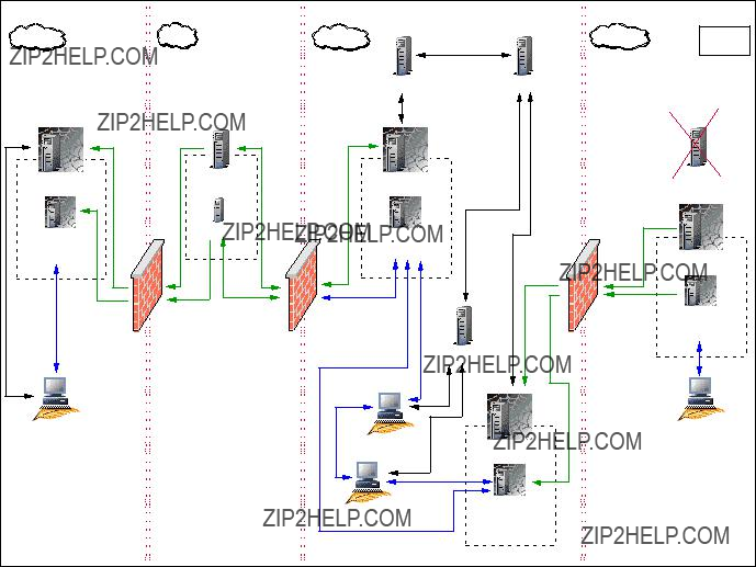
Implementation Planning Case Study: Solution B
In this scenario, the requirements imposed by CSI Corporation are the same as presented for Solution A. The goal for in this section is to provide an alternate solution design for CSI ??? in this case, a change on the existing physical design by eliminating the current Tivoli Endpoint Gateway installed in the Servers network zone. This will allow us to close the IOM Range and other Tivoli ports in the firewalls and decide upon a unidirectional communication from the Servers zone to the Internal zone. In this case, with a new Endpoint/gateway Proxy connection, only one pipe needs to be opened in Firewall 3. In terms of a firewall security solution, this architecture provides a great enhancement. In addition to that, there is only the need to use the RC Non-Standalone solutions.
Figure 2-5 depicts the proposed CSI Corporation Tivoli environment with an IBM Tivoli Remote Control Proxy solution, for Solution B.
Figure 2-5 Case study scenario with RC Proxy architecture - Solution B
88 IBM Tivoli Remote Control Across Firewalls

Similarly to Solution A, there are three main requests that need to be addressed:
???Controllers in the External zone connecting Targets in the Internal zone:
The change in the design has no affect on this request, and Controller 1 is able to connect to Target 1 using the A path, as described in ???Implementation Planning Case Study: Solution A??? on page 83.
???Controllers in the External zone connecting Targets in the Servers zone:
The second requirement is that Controller 1 needs to contact Target 2 in the Server zone. As shown in Figure 2-5, because the Endpoint Gateway was removed from the Server zone, a new Endpoint/Gateway Proxy B architecture needs to be deployed to manage Targets in the Server zone.
For Remote Control operations, a new RC Target Proxy B needs to be installed on top of the Endpoint Proxy B and it becomes automatically a Parent, as the Endpoint Proxy is a Parent. On the other side of Firewall 3, a new RC Controller Proxy B needs to be installed on top of the Gateway Proxy B, and, of course, this component becomes the Child. Using this architecture, the request from Controller 2 is forwarded from the A path to the B path using the Endpoint Proxy routing technology.
Important: Requests initiated by a Controller can be forwarded from one RC Target Proxy/RC Controller Proxy architecture to another RC Target Proxy/RC Controller Proxy architecture. However, these two architectures must be RC Proxy Non-Standalone solutions, because the request is transmitted from one part to the other using the routing technology of the Endpoint Proxy components.
For more information about the Endpoint Proxy routing technology, refer to the Firewall Security Toolbox User ???s Guide, GC23-4826 and to the Tivoli Enterprise Management Across Firewalls, SG24-5510.
???Controllers in the Internal zone connecting Targets in the Servers zone:
The third requirement is still raised by the CSI Level 3 support group. These administrators need to have remote control access to Targets in both Internal and Servers zone. Targets in the Internal zone will be managed by Controller 2 using the non-secure 1 IBM Tivoli Remote Control process. However, the Controller 2 could benefit from the RC Proxy architecture to get the Target 2 sited in the Servers zone. It just needs to connect to the RC Target Proxy B, which will transfer the request to the RC Controller Proxy B. So, the Controller 2 is able to contact the Target 2 using the B path.
Table 2-12, Table 2-13, and Table 2-14 summarize all of the necessary network communications ports that may help in configuring the RC Proxies, TFST components, as well as the firewalls of CSI Corporation.
Note that the ports provided in these tables are examples specific to this case study scenario.
Table 2-12 RC Proxy network ports for firewall 1 - Solution B
90 IBM Tivoli Remote Control Across Firewalls
Part 2
Part 2 Implementation
scenarios
92 IBM Tivoli Remote Control Across Firewalls

3
Chapter 3. Implementation scenario: Standalone Proxies
In this chapter we explain the techniques used to implement IBM Tivoli Remote Control 3.8 in a firewall environment. The scenario we describe will help you understand the requirements for establishing Remote Control sessions when a firewall is involved, using a more secure mechanism, the Remote Control Proxy technology in Standalone mode. These topics are covered:
???Our testing scenario: Using Remote Control Proxies in Standalone mode
???Remote Control data flow, TCP/IP ports used, and firewall configuration
???Remote Control Proxies installation and configuration
We make the following assumptions:
???You have a working knowledge of the TME?? architecture and of the IBM Tivoli Management Framework 4.1
???You have a basic understanding of Tivoli Firewall Security Toolbox 1.3 (TFST). Appendix A, ???Tivoli Firewall Security Toolbox overview??? on page 175 provides an overview of the main TFST components.
???You have a basic understanding of large enterprise network architecture, firewall and proxies.
3.1 Scenario overview
In this section, we provide an overview of our Remote Control in Standalone mode testing scenario. A typical Remote Control in Standalone mode is defined when the Tivoli Management Gateway (Gateway) and its Endpoints are separated from the Remote Control Controller by a firewall.
The goal of this scenario is to provide detailed information to the System Administrators of the requirements and considerations that will help them work with session management across a firewall.
Since firewalls restrict the communication channel, we will show how Remote Control can work through the firewall, respecting its restrictions, and how the Remote Control Proxies are used for this purpose.
We have included tables of information on ports that need to be configured in the firewall in order to establish Remote Control sessions, as well as pictures related to the scenario we are describing, outlining the flow of data, and a detailed description of the steps required to make such an environment work properly.
Wherever possible, we point out the differences between UNIX and non-UNIX platforms, trying to cover as many situations as possible.
In this testing scenario, we assume the IBM Tivoli Management Framework has been properly installed and that the communication between Endpoints and Gateways, TMR server, and managed nodes work as well. You can refer to the
Tivoli Enterprise Management Across Firewalls, SG24-5510 for information on this area. This is the basic requirement before configuring and installing IBM Tivoli Remote Control across firewalls. We also assume that the IBM Tivoli Remote Control 3.8 server component is already installed on the TMR server as well as on all Tivoli Gateways hosting the Endpoints, Controllers, and Targets. For additional information, refer to the IBM Tivoli Remote Control User???s Guide, SC23-4842.
3.2 Environment description
In our testing scenario, the goal was to reproduce the most common environment using all the required components in order to provide valuable inputs and illustrate our conclusions. We used different machine types and operating systems. Even though the goal here is not to test firewall products, we used different firewall products with this configuration, keeping in mind the services, protocol, and ports used by the Remote Control Proxies.
94 IBM Tivoli Remote Control Across Firewalls
As described in Chapter 2, ???Implementation planning??? on page 57, the following are important items to be considered when planning IBM Tivoli Remote Control 3.8 across firewalls:
???Firewall topology and its restrictions
???Placement of Remote Control Controller (RC Controller), Targets, Remote Control Controller Proxy (RC Controller Proxy), and remote Control Target Proxy (RC Target Proxy)
???Decision on Parent-Child relationship of RC Controller and RC Target Proxies
???Communication flow: unidirectional or bidirectional communication
???Hostname and the port used by the RC Controller and RC Target Proxies
The Remote Control Proxies are new components introduced by IBM Tivoli Remote Control 3.8 and are used to simplify the communication between Controller and Targets across firewalls. Remote Control Proxies can be installed on any machine on your environment, and don???t need necessarily to be installed on a machine part of the TME. We recommend that you refer to Chapter 2, ???Implementation planning??? on page 57 to check the supported platforms for this application.
An RC Target Proxy is the component that is connected to the Controllers acting as a Target. The RC Controller Proxy is the component that is connected to the Targets acting as a Controller. These two proxies then communicate to each other through the firewall, using the HTTP protocol.
Prior to installing any Remote Control Proxy component, you need to decide which one will be the Parent Proxy and which one will be the Child Proxy. Usually to get a better and more secure configuration, we recommend that you configure the RC Target Proxy as the Parent and the RC Controller Proxy as the Child. This is because the RC Target Proxy is usually connected to a few Controllers, while the RC Controller Proxy is usually connected to several Targets. Refer to Chapter 1, ???Remote Control sessions overview??? on page 3 for details.
3.2.1 Technical infrastructure
This section provides a description of our lab environment for the Standalone environment, showing the machine type, operating system, and Tivoli resource we installed on each machine.
For convenience, we installed some components on the same machine, but you can have them on different boxes.
Figure 3-1 illustrates the general testing scenario used in our lab.
Figure 3-1 General testing scenario
This scenario includes interconnected TMR using the Hub and Spoke architecture, two different Gateways and a set of Endpoints. One of the Gateways is placed in the DMZ (less secure side) to which the Target Endpoints belong, while the other one is placed on the more secure side, to which the Controller Endpoints belong.
Our Administrators have been defined in the TMR Spoke environment, where we have the Controllers. The intention here is to establish Remote Control sessions from TMR Spoke environment (more secure side) to DMZ (less secure side). In our scenario, we defined the Endpoint tic01006 to be a Controller and the Endpoints tic01005 and tic01007 to be the Targets.
96 IBM Tivoli Remote Control Across Firewalls

For our testing, we used the following products and release levels:
???Operating systems:
???IBM AIX 5.1
???Microsoft Windows 2000 Advanced Server
???Microsoft Windows 2000 Professional
???Tivoli Software:
???IBM Tivoli Management Framework 4.1
???IBM Tivoli Remote Control 3.8
We interconnected the Hub and Spoke TMR, using a two-way connection, and exchanged the following Tivoli resources:
???Administrator (two-way)
???AdministratorCollection (two-way)
???ManagedNode (two-way)
???Endpoint (two-way)
???PolicyRegion (two-way)
???ProfileManager (two-way)
???EndpointManager (one-way; only one time from the Spoke to the HUB TMR)
Note: We have not exchanged the RemoteControl resource because, in our scenario, there are no Controllers connected to the HUB TMR.
Information related to the interconnected TMRs, managed nodes, their status and IP addresses can be obtained by using odadmin command, as shown in both Example 3-1 for the TMR Hub and Example 3-2 for the TMR Spoke.
Example 3-1 Hub TMR region
We defined both TMRs and the managed node as Tivoli Gateway resources, as shown in the Example 3-3 and Example 3-4 that list the wgateway command output.
Example 3-3 Hub TMR Endpoint Gateway
We defined the machine tic01005 as the Gateway in the DMZ (less secure side) hosting the Targets Endpoints and the machine tic01002 as the Gateway on the more secure side hosting the Controllers Endpoints.
We installed the Remote Control Server on TMR Spoke/Gateway (tic01002), and on the Gateway standing on the less secure side of the firewall (tic01005).
Figure 3-2 shows how we implemented the Remote Control Proxies in the general testing scenario.
98 IBM Tivoli Remote Control Across Firewalls
Figure 3-2 RC Proxy Implementation
In this environment, we defined the machine tic01002 as RC Target Proxy and the machine tic01005 as RC Controller Proxy. In our case, both of these are also the Tivoli resources.
The RC Target Proxy has been defined as Parent Proxy, and the RC Controller Proxy has been defined as Child Proxy. We use a unidirectional connection, and we define the RC Target Proxy as the initiator.
3.2.2 Data flow description
In this section we describe the data flow in our network topology based on our testing scenario. We also highlight the ports used for the communication between each Remote Control component, preparing the base for 3.3.3, ???Firewall configuration table??? on page 108.

The schema reported in Figure 3-3 shows an overview of the data flow in our Remote Control StandAlone environment.
Figure 3-3 Remote Control Data Flow Overview
To briefly describe how the data flow structure is, we numbered each connection reported in Example 3-3, specifying the ports required to establish each connection. Following is a brief description of each number:
1.The Remote Control Controller connects to the RC Target Proxy using the proxy port specified in the rc_def_proxy policy method on the Spoke TMR. This policy method is only applied to the Policy Region in which the Remote Control Tool has been created. In our case the value of this port is 8888. The Controller itself uses a random port to establish a connection to port 8888 on the RC Target Proxy. This random port could also be fixed to a specific port by modifying the rc_def_ports policy method on the Spoke TMR. For more information on this matter, you can refer to the IBM Tivoli Remote Control User???s Guide, SC23-4842.
2.Since this is a unidirectional configuration, we defined the RC Target Proxy to be responsible for initiating the connection to the RC Controller Proxy. In our environment the RC Target Proxy uses a random port to establish a connection to port 30008 defined on the RC Controller Proxy. This random port could also be either a fixed port or use a pre-defined range of ports. Information on how to customize it is provided in 3.3.2, ???Remote Control Proxy configuration??? on page 104. Communications from the RC Target Proxy machine to port 30008 should be allowed by the firewall.
3.Then the RC Controller Proxy communicates with the Endpoint Target using a random port, while the Target listens on the default Remote Control port 2501.
100 IBM Tivoli Remote Control Across Firewalls
The ports defined as random on the Controller and RC Target Proxy could be customized specifying a single port or a range of ports, depending on the number of connections to be established. For example, we could restrict the ports usage for the communication between the RC Target Proxy Parent and all the RC Controller Proxies Children, so that the configuration on the firewall could be more restrictive. This is further explained in 3.3.2, ???Remote Control Proxy configuration??? on page 104.
3.3 Scenario installation and configuration
In this section, we describe the steps to install the Remote Control Proxies in the environment presented in Figure 3-2 on page 99, including general installation instructions and a table containing the information needed during the installation for both RC Target and RC Controller proxies. We also provide some configuration steps to complete the installation procedure.
Our testing scenario contains only one firewall. However, this scenario could be extended with a second firewall. This would create a demilitarized zone (DMZ) where the RC Target and RC Controller Proxy are not allowed to connect directly across multiple zones. In this case we could take advantage of the Relay function, provided by Tivoli Firewall Security Toolbox (TFST), which can be installed on the DMZ. The Relay would pass the information from the RC Target Proxy to the RC Controller Proxy and vice versa. Even though this new scenario would use the Relay component of the TFST, it is still considered a Remote Control StandAlone environment. For details, refer to Chapter 2, ???Implementation planning??? on page 57.
3.3.1 Remote Control Proxy installation
This section describes how to install:
???Remote Control Target Proxy
???Remote Control Controller Proxy
The installation of the Remote Control Proxy component must be done locally and can be done using either the GUI or silent methods, depending on the Install Shield mechanism. You can also take the advantage of other Tivoli Applications, such as IBM Tivoli Configuration Manager, by creating your own package with the Software Package Editor. For more information, refer to the IBM Tivoli Configuration Manager User???s Guide for Software Distribution, SC23-4711. In addition, you can refer to the IBM Tivoli Remote Control User???s Guide, SC23-4842 for the information about the silent installation.

The Remote Control Proxies components can be installed on any machine in your environment whether part of the TME environment or not. Refer to Chapter 2, ???Implementation planning??? on page 57, to check on the various supported operating systems and maintenance levels.
The Remote Control Proxies components code is shipped with the IBM Tivoli Remote Control 3.8 media, the same you used to install the IBM Tivoli Remote Control Server component. The installation process for the RC Target and RC Controller Proxies is the same and uses the same source image and path. The differences are in the configuration piece only. You can refer to Chapter 2, ???Implementation planning??? on page 57 for details.
In order to install the Remote Control Proxies, issue the following command:
On Windows:
<CD-ROM drive>\new\RCPROXY\w32-ix86\setup.exe
On AIX:
#. ./<CD-ROM drive>/new/RCPROXY/aix/install.sh ./setup.bin
Note: If the installation on UNIX never displays the GUI panel, make sure the /tmp file system is not 100% used.
Table 3-1 shows the configuration settings we used in our lab for this scenario during the RC Target Proxy installation.
Table 3-1 RC Target Proxy settings
102 IBM Tivoli Remote Control Across Firewalls
The above settings are mandatory and, once the installation is completed, all this information is stored in the rcproxy.cfg file located at the Remote Control Proxy installation directory. Inputs needed to modify the remote control Target Proxy configuration file are given in ???The rcproxy.cfg configuration file??? on page 104.
Table 3-2 shows the configuration settings we used in our lab for this scenario during the Remote Control Controller Proxy installation:
Table 3-2 RC Controller Proxy settings

The foregoing settings are mandatory and, once the installation is completed, all this information is stored in the rcproxy.cfg file located at the Remote Control Proxy installation directory. Inputs to modify the RC Controller Proxy configuration file are given in ???The rcproxy.cfg configuration file??? on page 104.
3.3.2 Remote Control Proxy configuration
This section describes some of the configuration steps to modify the Remote Control Proxy settings. The Remote Control Proxy configuration is done at installation time and can be changed at any time by manipulating the following configuration files:
???Remote Control Proxy configuration file: rcproxy.cfg
???Remote Control Proxy routing table: rcproxy.route
???Remote Control policy method: rc_def_proxy
The rcproxy.cfg configuration file
The rcproxy.cfg file contains all the information related to the Remote Control Proxy, such as Proxy type, ports used, Parent/Children/Relay information, connection type, role, etc.
This file is located in the Remote Control Proxy installation directory that by default is c:\Program File\Tivoli Systems\Remote Control Proxy on Windows and /opt/Tivoli Systems/Remote Control Proxy on UNIX.
Example 3-5 shows the RC Target Proxy configuration file, based on the values we provided in Table 3-1 on page 102, immediately after the installation process.
Example 3-5 Remote Control Target Proxy configuration file
[log] log-file=rcproxy.log debug-level=3 max-size=1
[rcproxy] proxy-port=8888 proxy-type=Target proxy-interface=tic01002 cmdline-port=9000 [communication-layer]
children-local-host=tic01002 children-local-port=2888 children-remote-list=tic01005+30008 children-cm-type=cm-tcp-unidirectional buffer-size=1024
[children-cm-info] connection-mode=client
104 IBM Tivoli Remote Control Across Firewalls
Example 3-6, instead, shows the RC Controller Proxy configuration file as result of the installation process, and the values provided in Table 3-2 on page 103.
Example 3-6 Remote Control Controller Proxy configuration file
[log] log-file=rcproxy.log debug-level=4 max-size=1
[rcproxy] proxy-type=Controller proxy-label=tic01005 cmdline-port=9999 [communication-layer] parent-local-port=30008 parent-remote-host=tic01002 parent-remote-port=2888
parent-cm-type=cm-tcp-unidirectional buffer-size=1024
[parent-cm-info] connection-mode=server
In order to have a more restrictive security communication between the RC Target and RC Controller Proxies, we decided to define a range of ports the RC Target Proxy could communicate with the RC Controller Proxy. This can be achieved by using the local-port-range parameter in the [children-cm-info] clause of the rcproxy.cfg file. In our scenario, we specified a port range with only two ports (4000-4001) that will allow this RC Target Proxy, acting as Parent, to have only two Child Proxies connect to it. Example 3-7 shows the resulting rcproxy.cfg file on the RC Target Proxy:
Example 3-7 Target Proxy local-port-rage definition
[log] log-file=rcproxy.log debug-level=3 max-size=1
[rcproxy] proxy-port=8888 proxy-type=Target proxy-interface=tic01002 cmdline-port=9000 [communication-layer]
children-local-host=tic01002 children-local-port=2888 children-remote-list=tic01005+30008 children-cm-type=cm-tcp-unidirectional buffer-size=1024

[children-cm-info] connection-mode=client
[children-cm-info] connection-mode=client local-port-range=4000-4001
In order to make these changes effective, we need to stop/start the RC Target Proxy service.
The rcproxy.route routing table configuration file
The rcproxy.route file defines the route to the Target Endpoints. It contains the list of all the Targets the Controller needs to connect to and the related RC Controller Proxy which they belong to. It contains static routing table information for the Remote Control Proxy.
Example 3-8 shows the rcproxy.route file reflecting the settings used in our testing scenario:
Example 3-8 Remote Control Proxy routing table configuration file
#This file contains static routing table information
#for remote control proxy
#Each line specifies an Endpoint (Target) label and the label
#of the Controller Proxy that serves it, separated by a comma like this:
#When you specify a label you can use the following
#wildcard characters:
To correctly set the routing table information, you need to specify the Endpoint label and its correspondent RC Controller Proxy in each line of the rcproxy.route file.
This file is located in the Remote Control Proxy installation directory that by default is c:\Program File\Tivoli Systems\Remote Control Proxy on Windows and /opt/Tivoli Systems/Remote Control Proxy on UNIX.
106 IBM Tivoli Remote Control Across Firewalls
The rc_def_proxy policy method
In order to customize the Remote Control Proxy in a Standalone environment, it is necessary to modify the rc_def_proxy policy method accordingly. This file determines how the Remote Control Proxies usage will be done and how the Controller can connect to the Targets across the firewall.
Example 3-9 shows the settings we used in our rc_def_proxy policy method file:
Example 3-9 The rc_def_proxy policy method contents
#!/bin/sh
#
#Default value: NO
echo "YES manual 9.3.4.169 8888" exit 0
When using the StandAlone proxy mechanism, it is required to provide the following configuration information:
???Configuration type
???RC Target Proxy IP address
???RC Target Proxy port
In a Standalone scenario, the configuration type must always be set to manual. This means that the Controller will always use the IP address provided in the policy method to reach the RC Target Proxy. The Remote Control Proxy port identifies the port the RC Target Proxy listens for requests from the Controller, which in our scenario is 8888.
The wgetpolm and wputpolm commands are used to modify the rc_def_proxy policy method settings. Example 3-10 shows how to perform these changes in our testing scenario, where we use our own policy, named STDAlone, and not the default policy RemoteControl_PDO:
Example 3-10 How to modify the rc_def_proxy policy method
wlpol -d RemoteControl RemoteControl_PDO STDAlone
wgetpolm -d RemoteControl STDAlone rc_def_proxy > temp_rc_def_proxy.sh
modify the rc_def_proxy.sh accordingly to Example 3-9
wputpolm -d RemoteControl STDAlone rc_def_proxy < temp_rc_def_proxy.sh
3.3.3 Firewall configuration table
This section describes the correlation between the firewall customization and the Tivoli environment to be implemented, providing the information a firewall administrator should need in order to configure the ports properly on the firewall to make the remote control session working, for this particular scenario.
Table 3-3 shows the components that will communicate through the firewall and the ports they use in our scenario.
Table 3-3 Scenario firewall configuration table
(1) Defined by the local-port-range parameter, as described in the Example 3-7, the Port field should be in the range (4000-4001).
The schema provided in the previous table would allow for a data flow shown in
Figure 3-4 Remote Control Data Flow Overview
108 IBM Tivoli Remote Control Across Firewalls

3.3.4 Remote Control Proxy startup
This section describes how you can start up the Remote Control Proxies.
Once the installation has been completed, the RC Target and RC Controller proxies have been properly configured and the firewall administrator has granted the access to ports needed by the Tivoli application to work properly, then you can check if the proxy mechanism works by starting the RC Target and RC Controller Proxy services.
By default, after a successful installation of Remote Control Proxy, the proxy service is automatically started. Actually, both RC Target and RC Controller Proxy can be started using the rcproxy command provided with the installation of the Proxy component.
For more information, you can refer to the IBM Tivoli Remote Control User???s Guide, SC23-4842.
Example 3-11 shows how to startup the remote control proxy on AIX machine:
Example 3-11 Startup of Remote Control Proxy on AIX operating system
# pwd
/usr/local/Tivoli/Remote Control Proxy #./rcproxy &
In order to start the RC Proxy service installed on Windows 2000, you need to issue the rcproxy command. Figure 3-5 shows Service Applet window with the Remote Control Proxy service status.
Figure 3-5 Startup of Remote Control Proxy using Service Applet
The command rcproxy can also be used for other tasks, such as to check how many proxy connections are active, to stop the Proxy service and to kill any of the active Proxy sessions.
Once the Target and Controller Proxy are up and running, their communication can be checked in two ways:
???Checking the rcproxy.log file
???Running the netstat command
Example 3-12 and Example 3-13 show the rcproxy.log files contents for RC Target and RC Controller Proxy components. The last few lines of each of the logs show that the connections are working and that the communication has been established through the firewall:
Example 3-12 The rcproxy.log: RC Target Proxy log file
110 IBM Tivoli Remote Control Across Firewalls
Example 3-13 The rcproxy.log: RC Controller Proxy log file
In order to check which ports these Proxies are using to communicate and to verify that no other ports are actually being used, we can use any network status command, such as netstat -a command or similar. Example 3-14 and Example 3-15 show the output of the netstat -a command on both the RC Target Proxy and RC Controller Proxy.
Example 3-14 The netstat output collected on the RC Target Proxy
Example 3-15 The netstat output collected on the Controller Proxy
Active Connections
The highlighted lines in Example 3-14 and Example 3-15 show the connection between the RC Proxies components.
Also notice that the both netstat outputs were collected before any remote control session was actually started
112 IBM Tivoli Remote Control Across Firewalls
Example 3-16 lists the output of the rcproxy command, showing no active connections:
Example 3-16 The output of the rcproxy -list command
# ./rcproxy -list total sessions = 0
03/02/11 10:27:30 0 1 releaseLock [id=0x2020bfd8] - pthread_mutex_unlock() failed (e=1)
03/02/11 10:27:30 0 1 releaseLock [id=0x2020bf98] - pthread_mutex_unlock() failed (e=1)
An example of netstat and rcproxy -list commands output during an active session is provided in the section ???Remote Control Proxy startup??? on page 133.
Attention: The rcproxy command included in Example 3-16 shows some error messages that can be ignored. That is because the RC Proxies are not installed on top of the TFST Proxies (Endpoint Proxy or Gateway Proxy).
114 IBM Tivoli Remote Control Across Firewalls

4
Chapter 4. Implementation scenario: Tivoli Firewall Security Toolbox
In this chapter we describe the techniques used to implement IBM Tivoli Remote Control 3.8 in a firewall environment. The scenario we present will help you understand the requirements for establishing Remote Control sessions when firewall is involved, using a more secure mechanism, the Remote Control Proxy technology using the Tivoli Firewall Security Toolbox. These topics are covered:
???Our testing scenario: Remote Control Proxies implementation using the Tivoli Firewall Security Toolbox (TFST) environment
???Data flow, TCP/IP ports used, and firewall configuration
???Remote Control Proxies installation and configuration
We make the following assumptions:
???You have a working knowledge of the TME architecture and of the IBM Tivoli Management Framework 4.1
???You have a basic understanding of Tivoli Firewall Security Toolbox 1.3 (TFST). Appendix A, ???Tivoli Firewall Security Toolbox overview??? on page 175 provides an overview of the main TFST components.
???You have a basic understanding of large enterprise network architecture, firewall and proxies.
4.1 Scenario overview
In this section we provide an overview of our Remote Control Non-Standalone testing scenario. A typical Remote Control Non-Standalone architecture is implemented when the firewall stands between the Endpoint Targets and the Endpoint Gateway. A common environment, for example, could be managing the Endpoint in the DMZ with the Gateway located at the most secured zone.
The goal of this scenario is to provide detailed information to the System Administrator of the requirements and considerations that will help him to work with session management across the firewall. We provide as much information as possible to deeply describe the implementation of Remote Control using the TFST component functionalities. We also show a diagram outlining the data flow mechanism and include the firewall configuration tables in order to allow the successful usage of IBM Tivoli Remote Control across the firewalls.
In this testing scenario we assume that the IBM Tivoli Management Framework 4.1 and the Tivoli Firewall Security Toolbox 1.3 have been properly installed and configured and that any down call to the Endpoint can be successfully executed as the up call to the Gateway. You can refer to the Firewall Security Toolbox User ???s Guide, GC23-4826 if you have any problems in this area. Moreover, we assume you have already installed and configured the Endpoint Proxy, Relay, and Gateway Proxy components, and that the communication works from the Framework point of view.
These are the basic requirements before configuring and installing IBM Tivoli Remote Control across firewalls. We assume that IBM Tivoli Remote Control 3.8 server component is already installed on the TMR and all Tivoli Gateways hosting the Endpoints, controllers and Targets. Refer to IBM Tivoli Remote Control User???s Guide, SC23-4842 for details.
4.2 Environment description
In our testing scenario, the goal was to reproduce the most common environment using all the required components in order to provide valuable inputs and illustrate our conclusions. We used different machine types and operating systems. Even though the goal here is not to test firewall products, we used different firewall products with this configuration, keeping in mind the services, protocol, and ports used by the Remote Control Proxies.
116 IBM Tivoli Remote Control Across Firewalls
We demonstrate how the Remote Control Proxy will allow remote control connections through the firewall with minimal impact on the connection policies enforced by the firewall itself. We explain the seamless integration the Remote Control Proxies have with the Tivoli Firewall Security Toolbox and its ability to handle concurrent sessions.
Complex network may impose the usage of Remote Control across multiple firewalls. Since Remote Control uses the TFST technology, it can take advantage of the Relay component of TFST to bridge two proxies across multiple firewalls. Relays cannot be shared in integrated scenario between Remote Control Proxy and TFST, so we need to have two different Relay entities; one will be used by the Remote Control Proxy, and the other one by the TFST. In this case it is necessary to install another Relay instance on the environment. All those Relay instances must be installed on the same physical machine. For additional information, refer to Chapter 2, ???Implementation planning??? on page 57.
4.2.1 Technical infrastructure
This section provides a detailed description of our TFST environment, showing the machine type, operating system, and Tivoli resources we installed on each machine.
Figure 4-1 illustrates the general testing scenario used in our lab.
TMR Hub
Hub TMR server
AIX 5.1 - tic01002
TMR Spoke
Spoke TMR server
AIX 5.1 - tic01010
Endpoint
Windows TS server
Endpoint
Windows - tic01006
Endpoint Gateway
AIX 5.1 - tic01010
Endpoint Proxy
Windows - tic01003
Firewall 2
Endpoint
Gateway Proxy
Windows - tic01005
Endpoint
Windows - tic01007
Figure 4-1 General TFST testing scenario
In our testing scenario we have defined two firewalls dividing the Tivoli environment into three zones: a more secure zone where all TMR Servers and Endpoint Gateways reside, a De-Militarized Zone (DMZ), and a less secure zone where the Targets Endpoints are located.
118 IBM Tivoli Remote Control Across Firewalls

For our testing we used the following products and release levels:
???Operating systems:
???IBM AIX 5.1
???Microsoft Windows 2000 Advanced Server
???Microsoft Windows 2000 Professional
???Tivoli Software:
???IBM Tivoli Management Framework 4.1
???IBM Tivoli Remote Control 3.8
???Tivoli Firewall Security Toolbox 1.3
We interconnected the Hub and Spoke TMR, using a two-way connection, and exchanged the following Tivoli resources:
???Administrator (two-way)
???AdministratorCollection (two-way)
???ManagedNode (two-way)
???Endpoint (two-way)
???PolicyRegion (two-way)
???ProfileManager (two-way)
???EndpointManager (one-way, and only once from the Spoke to the HUB TMR)
Note: We have not exchanged the Remote Control resource because, in our scenario, there are no controllers connected to the HUB TMR.
For this scenario, we assume that all Administrators are on the more secure side of our network. Therefore, the Remote Control Server is installed on both of the TMR Servers; and one of the Endpoints in the more secure zone will be the Remote Control Controller. The Administrators need to have remote Control access to the Endpoint located in the less secure zone.
Figure 4-2 shows how we implemented the Remote Control Proxy technology based on the existing TFST configuration.
Figure 4-2 Remote Control Proxy Implementation in a TFST environment
Based on Figure 4-2, we configured our testing scenario as follows:
???An RC Target Proxy needs to be installed on the same machine as the Endpoint Proxy. Because this Endpoint Proxy is a Parent in the TFST structure, this RC Target Proxy automatically becomes a Parent.
???Per security guidelines, the communication is defined as unidirectional. Therefore, only the RC Target Proxy on the secure zone can be the connection initiator.
120 IBM Tivoli Remote Control Across Firewalls
???Since there is a Relay placed in the DMZ to allow the proxies communication across multiple firewalls (Endpoint Proxy in the more secure side and the Gateway Proxy in the less secure side), we need to define an extra Relay instance on this network that will allow the communication between the RC Target Proxy and the RC Controller Proxy. This Relay will be configured as a Child of the RC Target Proxy and a Parent of the RC Controller Proxy.
???An RC Controller Proxy needs to be installed on the same machine as the Gateway Proxy. This RC Controller Proxy will be configured to be a Child of the second instance of the Relay. Because the RC Controller Proxy is running on the Gateway Proxy machine, its label should be exactly the same as the Gateway Proxy.
???Since the communication is defined as unidirectional, and the RC Target Proxy is the initiator, the RC Controller Proxy will be defined as listener.
Table 4-1 shows a summary of the configuration of our environment, providing hostname, operating system, and related Tivoli resources installed.
Table 4-1 Summary of Framework and Remote Control resources
4.2.2 Data flow description
This section provides a description of the data flow in our network topology, based on our testing scenario, and also highlights the ports used for the communication between each RC Proxy and TFST component, preparing the basis for 4.2.3, ???Firewall configuration tables??? on page 124.
The schema reported in Figure 4-3 shows an overview of the data flow in our Non-Standalone case study scenario.
Figure 4-3 Data flow overview: Non-Standalone scenario
To briefly describe how the data flow structure is, we numbered each connection reported in Figure 4-3 specifying the ports required to establish each connection. Follow a brief description of each number:
1.The Remote Control Controller connects to the RC Target Proxy using the proxy port specified in the rc_def_proxy policy method on the Spoke TMR. This policy method is only applied to the Policy Region in which the Remote Control Tool has been created. In our case the value of this port is 5020. The Controller itself uses a random port to establish a connection to port 5020 on the RC Target Proxy. This random port could also be fixed to a specific port by modifying the rc_def_ports policy method on the Spoke TMR. For more information on this matter you can refer to the IBM Tivoli Remote Control User???s Guide, SC23-4842. The RC Target Proxy contacts the Endpoint Proxy to find out the path to the requested Target.
2.The Endpoint Proxy then provides to the RC Target Proxy the hostname of the Gateway Proxy responsible for that Target. The RC Target Proxy uses that information to initiate the connection to the RC Controller Proxy. In our environment the RC Target Proxy uses a pre-defined range of ports (4000-4010) to establish a connection to port 7020 defined on the second instance of the Relay. This range of ports need to be defined after the installation of the RC Target Proxy. Information on how to customize it will be provided in 4.3.2, ???Remote Control Proxy configuration??? on page 129. Communications from the RC Target Proxy machine to port 7020 should be allowed by firewall 1.
122 IBM Tivoli Remote Control Across Firewalls
3.The second instance of the Relay is then responsible for initiating the connection with the RC Controller Proxy. This Relay uses a pre-defined range of ports (4023-4024) to establish a connection to port 8020 defined on the RC Controller Proxy. This range of ports needs to be defined after the installation of the second instance of the Relay. Information on how to customize it is given in 4.3.2, ???Remote Control Proxy configuration??? on page 129. Communications from the RC Target Proxy machine to port 7020 should be allowed by firewall 2.
4.Then the RC Controller Proxy communicates with the Endpoint Target using a random port, while the Target listens on the default Remote Control port 2501.
Table 4-2 summarize the ports that we used to configure both Remote Control Proxies and the Relay.
Table 4-2 Summary of port configuration
When a remote Control session is initiated, the Remote Control Controller connects to the RC Target Proxy running on the Endpoint Proxy machine. When the Target Endpoint is connected to a Gateway Proxy, it is registered in the Endpoint Manager using the Endpoint Proxy IP address. The RC Target Proxy queries the Endpoint Proxy about the actual Endpoint???s IP address and port and collects this information. The Endpoint Proxy also gives the Gateway Proxy label to the RC Target Proxy.
Since this label must be the same as the Controller Proxy, the RC Target Proxy also knows the Controller Proxy it needs to connect to. The RC Target Proxy then forwards the request to the RC Controller Proxy through the specified Relay instance. When the request is received by the RC Controller Proxy, it will be responsible for connecting to the IP address and port number of the Endpoint Target it has just collected.
4.2.3 Firewall configuration tables
This section provides a correlation between firewall customization and the Tivoli environment to be implemented, providing the information a firewall administrator should need in order to configure the ports properly on all the firewalls to make the remote control session working, for this particular scenario.
Table 4-3 shows the components that will communicate through firewall 1 and the ports they use in our scenario.
Table 4-3 Firewall 1 configuration table
Table 4-4 shows the components that will communicate through firewall 2 and the ports they use in our scenario.
Table 4-4 Firewall 2 configuration table
124 IBM Tivoli Remote Control Across Firewalls
The port range must have as many ports as the number of Child Proxies the related proxy has. In our example we assume that the RC Target Proxy could have up to 10 additional Child Proxies, while the Relay could have 2 Child Proxies.
4.3 Scenario installation and configuration
This section describes scenarios for installing RC Target and Controller Proxies in our Non-Standalone environment. It also includes the configuration steps needed in order to properly customize the Proxies and to allow the Remote Control sessions across firewalls, according to the settings given in 4.2.3, ???Firewall configuration tables??? on page 124. The installation is performed based on the environment presented in Figure 4-2 on page 120.
4.3.1 Remote Control Proxy installation
This section describes how to install:
???Remote Control Target Proxy
???Relay instance used by Remote Control
???Remote Control Controller Proxy
The installation of the Remote Control Proxy component must be done locally and can be done using either the GUI or silent methods depending on the Install Shield mechanism. You can also take the advantage of other Tivoli Applications, such as IBM Tivoli Configuration Manager creating your own package with the Software Package Editor. For more information, see the IBM Tivoli Configuration Manager User???s Guide for Software Distribution, SC23-4711. In addition, you can refer to the IBM Tivoli Remote Control User???s Guide, SC23-4842 for information about the silent installation.
The installation procedure for the RC Target and Controller Proxies are the same as we presented for the StandAlone scenario as described in the 3.3.1, ???Remote Control Proxy installation??? on page 101. However, the RC Target Proxy must be installed on the same machine as the Endpoint Proxy, and the RC Controller Proxy must be installed on the same machine as the Gateway Proxy.
The Remote Control Proxies components code is shipped with the IBM Tivoli Remote Control 3.8 media, the same that you used to install the IBM Tivoli Remote Control Server component. The installation process for the RC Target and RC Controller Proxies is the same and uses the same source image and path. The differences are in the configuration piece only. You can refer to Chapter 2, ???Implementation planning??? on page 57 for details.
RC Target Proxy installation
In our testing scenario the RC Target Proxy component should be installed on Windows 2000 Server operating system. The installation is performed using the Install Shield mechanism running the setup.exe command from the IBM Tivoli Remote Control 3.8 media as follows:
<CD-ROM drive>\new\RCPROXY\w32-ix86\setup.exe
As soon as the installation process starts, it automatically detects the TFST code already installed on the machine. Since this installation detects an Endpoint Proxy installation, the RC Target Proxy will be automatically configured as a Parent Proxy.
Table 4-5 shows the configuration settings we used in our lab for this scenario during the RC Target Proxy installation.
Table 4-5 RC Target Proxy installation settings
(*) This parameter is mandatory during the installation. Since the connection type is unidirectional and the RC Target Proxy is configured as initiator, port 6020 will never be used.
126 IBM Tivoli Remote Control Across Firewalls
For additional information related to the Remote Control Proxy installation you can refer to the IBM Tivoli Remote Control User???s Guide, SC23-4842.
Relay instance used by Remote Control
In our testing scenario we have to install a second instance of the Relay to be used that will bridge the RC Target and Controller Proxies. The installation of the Relay component is started by the TivoliRelay.exe command provided by the Tivoli Firewall Security Toolbox 1.3 included in the IBM Tivoli Management Framework 4.1media. On Windows 2000 Advanced Server, issue the following command:
<CD-ROM>\tier1\new1\FST\Relay\w32-ix86\TivoliRelay.exe
Table 4-6 shows the configuration settings we used in our lab for this scenario during the Relay installation.
Table 4-6 Relay instance installation settings

(*) This parameter is mandatory during the installation. Since the connection type is unidirectional and the Relay is configured as listener, port 6020 will never be used.
RC Controller Proxy installation
In our testing scenario the RC Controller Proxy component should be installed on the Windows 2000 Server operating system. The installation is performed using the Install Shield mechanism running the setup.exe command from the IBM Tivoli Remote Control 3.8 media as follows:
<CD-ROM drive>\new\RCPROXY\w32-ix86\setup.exe
As soon as the installation process starts, it automatically detects the TFST code already installed on the machine. Since this installation detects a Gateway Proxy installation, the RC Controller Proxy will be automatically configured as a Child Proxy. In addition to that, the Gateway Proxy and the RC Controller Proxy share some TFST libraries and therefore they must have the same label.
Table 4-7 shows the configuration settings we used in our lab for this scenario during the RC Controller Proxy installation.
Table 4-7 RC Controller Proxy installation settings
128 IBM Tivoli Remote Control Across Firewalls

After installing the RC Controller Proxy, all the setting are stored in the rcproxy.cfg file placed in the installation path directory. The file contents appear as shown in th Example 4-1.
Example 4-1 RC Controller Proxy configuration file
[log] log-file=rcproxy.log debug-level=3 max-size=1
[rcproxy]
proxy-label=tic01005-gw
proxy-type=controller cmdline-port=3333 [communication-layer] parent-local-port=8020 parent-remote-host=tic01004 parent-remote-port=7021 parent-cm-type=cm-tcp-unidirectional buffer-size=1024
[parent-cm-info] connection-mode=server
In our testing scenario we configured our Gateway Proxy machine specifying its label to the value tic01005-gw. As you can see from the example above, the Proxy label of our RC Controller Proxy is the same of the Gateway Proxy. This is automatically set by the installation process when we install the Controller Proxy, since the installation detects the TFST installation on the Controller Proxy machine and pick up this information.
4.3.2 Remote Control Proxy configuration
This section describes some of the configuration steps to modify the Remote Control Proxy settings. The Remote Control Proxy configuration is done at installation time and can be changed at any time by manipulating the following configuration files:
???Remote Control Proxy configuration file: rcproxy.cfg
???Relay configuration file: Relay.cfg
???Remote Control policy method: rc_def_proxy
The rcproxy.cfg configuration file
The rcproxy.cfg file contains all the information related to the Remote Control Proxy, such as Proxy type, ports used, Parent/Children/Relay information, connection type, role, etc.

This file is located in the Remote Control Proxy installation directory that, by default, is c:\Program File\Tivoli Systems\Remote Control Proxy on Windows and /opt/Tivoli Systems/Remote Control Proxy on UNIX.
Example 4-2 shows the RC Target Proxy configuration file based on the values we provided in Table 4-5 on page 126 immediately after the installation process.
Example 4-2 RC Target Proxy configuration file example
[log] log-file=rcproxy.log debug-level=3 max-size=1
[rcproxy]
epp-directory=C:\Tivoli\Tivoli Systems\Tivoli Endpoint Proxy proxy-port=5020
proxy-type=Target cmdline-port=3333 [communication-layer] Children-local-port=6020 Children-remote-list=tic01004+7020
Children-cm-type=cm-tcp-unidirectional buffer-size=1024
[Children-cm-info] connection-mode=client
In order to have a more restrictive security communication between the RC Target and Relay, we decided to define a range of ports the RC Target Proxy could communicate with the Relay. This can be achieved by using the local-port-range parameter in the [children-cm-info] clause of the rcproxy.cfg file. In our scenario, we specified a port range with only 11 ports (4000-4010) that will allow this RC Target Proxy, acting as Parent, to have up to 11 Child Proxies connect to it. Example 4-3 shows the resulting rcproxy.cfg file on the RC Target Proxy:
Example 4-3 Modification settings example
[log] log-file=rcproxy.log debug-level=3 max-size=1
[rcproxy]
epp-directory=C:\Tivoli\Tivoli Systems\Tivoli Endpoint Proxy proxy-port=5020
proxy-type=Target cmdline-port=3333 [communication-layer] Children-local-port=6020
130 IBM Tivoli Remote Control Across Firewalls

Children-remote-list=tic01004+7020 Children-cm-type=cm-tcp-unidirectional buffer-size=1024
[Children-cm-info] connection-mode=client
local-port-range=4000-4010
In order to make these changes effective we need to stop/start the RC Target Proxy service.
The Relay.cfg configuration file
The relay.cfg file contains all the information related to the Relay settings we specified during the Relay component installation,. This file is located in the Relay installation directory and can be modified at any time. Example 4-4 shows the Relay configuration file based on the values we provided in Table 4-6 on page 127 immediately after the installation process.
Example 4-4 The Relay.cfg after the installation
[communication-layer] Children-local-port=7021 Children-remote-list=tic01005+8020 parent-local-port=7020 parent-remote-host=tic01003 parent-remote-port=6020 parent-cm-type=cm-tcp-unidirectional Children-cm-type=cm-tcp-unidirectional [log]
log-file=Relay.log debug-level=3 max-size=1 [parent-cm-info] connection-mode=server [Children-cm-info] connection-mode=client
In order to have a more restrictive security communication between the Relay and the RC Controller Proxy, we decided to define a range of ports the RC Target Proxy could communicate with the Relay. Similarly to the RC Proxies, this can be achieved by using the local-port-range parameter in the [children-cm-info] clause of the Relay.cfg file. In our scenario, we specified a port range with only 2 ports (4023-4024) that will allow this Relay to act as Parent for up to 2 Child Proxies. Example 4-5 shows the resulting rcproxy.cfg file on the Relay:

Example 4-5 The Relay.cfg file after the changes
[communication-layer] Children-local-port=7021 Children-remote-list=tic01005+8020 parent-local-port=7020 parent-remote-host=tic01003 parent-remote-port=6020 parent-cm-type=cm-tcp-unidirectional Children-cm-type=cm-tcp-unidirectional [log]
log-file=Relay.log debug-level=3 max-size=1 [parent-cm-info] connection-mode=server [Children-cm-info] connection-mode=client
local-port-range=4023-4024
In order to make these changes effective we need to stop/start the Relay service.
The rc_def_proxy policy method
In order to customize the Remote Control Proxy in a Non-Standalone environment, it is necessary to modify the rc_def_proxy policy method accordingly. This file determines how the Remote Control Proxies usage will be done and how the Controller can connect to the Targets across the firewall.
Example 4-6 shows the settings we used in our rc_def_proxy policy method file:
Example 4-6 The rc_def_proxy policy method contents
#!/bin/sh
# Default value: NO echo "YES auto 5020" exit 0
When using the Non-Standalone architecture, it is required to provide the following configuration information:
???Configuration type
???RC Target Proxy port
In a Non-Standalone scenario, the configuration type must always be set to auto., meaning that the Controller will always use the Endpoint Proxy address to reach the RC Target Proxy. The Remote Control Proxy port identifies the port the RC Target Proxy listens for requests from the Controller, which in our scenario is 5020.
132 IBM Tivoli Remote Control Across Firewalls
The wgetpolm and wputpolm commands are used to modify the rc_def_proxy policy method settings. The procedure is similar to the process shown for the Standalone case study scenario in Example 3-10 on page 107.
4.3.3 Remote Control Proxy startup
The process for starting the Remote Control Proxies was described in 3.3.4, ???Remote Control Proxy startup??? on page 109 and is similar when installed on a Non-Standalone environment. In this section we just provide the content of the rcproxy.log file for both the RC Target and Controller Proxies. Since there is a new instance of the Relay exclusive for the Remote Control communications, we also provide the content of the Relay.log file. The highlighted lines on the following examples show that the connections between the components separated by a firewall have been established.
Example 4-7 shows the RC Target Proxy log file.
Example 4-7 The rcproxy.log: RC Target Proxy log file
Example 4-8 shows the Relay log file.
Example 4-8 The Relay.log: Relay log file contents
Example 4-9 shows the RC Controller Proxy log file.
Example 4-9 The rcproxy.log: RC Controller Proxy log file
134 IBM Tivoli Remote Control Across Firewalls
In order to check which ports these Proxies are using to communicate and to verify that no other ports are actually being used, we can use any network status command, such as the netstat -a command or similar.
Example 4-10 shows the output of the netstat -a command on the RC Target Proxy.
Example 4-10 The netstat output collected on the RC Target Proxy
Active Connections
Example 4-11 shows the output of the netstat -a command on the Relay.
Example 4-11 The netstat output collected on the Relay
Active Connections
Example 4-12 shows the output of the netstat -a command on the RC Controller Proxy. Notice also that it shows an active connection between the RC Controller Proxy and the Target.
Example 4-12 The netstat output collected on the Controller Proxy
Active Connections
The highlighted lines in the foregoing examples show the connection between the RC Proxies and Relay components.
Also notice that both netstat outputs were collected before any remote control session was actually started.
136 IBM Tivoli Remote Control Across Firewalls
Example 4-13 lists the output of the rcproxy command that shows the active connection.
Example 4-13 The output of the rcproxy -list command
id=1, Target=tic01007, proxy_label=n/a total sessions = 1
138 IBM Tivoli Remote Control Across Firewalls
Part 3
Part 3 Troubleshooting
140 IBM Tivoli Remote Control Across Firewalls

5
Chapter 5. Troubleshooting techniques
IBM Tivoli Remote Control 3.8 aims to establish remote control session across firewalls using the Remote Control Proxy technology. While the systems administrator can perform many tasks relatively easy, the code Tivoli provides to achieve those tasks is extraordinarily complex. With the solid foundation of the Tivoli Management Framework, this complexity can remain largely masked from the administrator. However, with such a sophisticated set of products, there will be occasions when those designing, testing, and implementing Tivoli solutions will encounter situations that are not resolved by reference to product manuals alone.
In problem-solving situations, you need to understand what is going on between the product components, what messages and trace output means, and what extra actions you can take to try to resolve a problem.
The following troubleshooting topics are discussed in this chapter:
???Generic problem determination outline
???Session startup with emphasis on Framework, Tivoli Firewall Security Toolbox, and RC Proxies problem determination processes
???Session management
???Standalone environment
???Troubleshooting Remote Control Proxies examples
???Troubleshooting firewall information
5.1 Generic problem determination outline
To obtain an overall picture of what is happening on the IBM Tivoli Remote Control side when a session is established through a firewall, there are several troubleshooting steps to follow and logs that need to be analyzed.
You could face problems during:
???Session startup
???Session management
In order to help you isolate problems you experience with the Remote Control Proxies, we provide general troubleshooting guidelines and processes that may offer you a way to organize your problem determination strategy.
5.1.1 Session startup
As soon as the Remote Control Tool is started, the pcremote process is triggered. It performs several checks before starting the session and connecting the RC Controller to the RC Target machine. All the steps performed by the pcremote process are tracked in the pcremote trace file.
This troubleshooting section does not describe the pcremote traces analysis, since the objective here is to only debate the proxy's components. Anyway, by providing general troubleshooting ideas for other items, like the IBM Tivoli Management Framework, Tivoli Firewall Security Toolbox (TFST), and the RC Proxies, this can help you to understand the whole picture of the modules dependencies.
Next, you will find the complete process that is used to determine if there is a problem with the Remote Control Proxies. As IBM Tivoli Remote Control 3.8 has been designed to work with both IBM Tivoli Management Framework and the TSFT, IBM Tivoli Remote Control???s functionality is highly dependent on those components. Thus, before analyzing any Remote Control logs or trace files, you need to be sure that any of the IBM Tivoli Management Framework and TFST components are working properly.
142 IBM Tivoli Remote Control Across Firewalls
The following sections show a series of flows that represent the fundamental steps you need to perform for troubleshooting issues when establishing Remote Control sessions through the firewall, from the time you click the Run button of the Remote Control Tool, to the time the session between the RC Controller and the RC Target is established.
Endpoint problem determination process
Before starting the problem determination, we recommend that you follow these steps in order to have a clear picture of what is going wrong:
1.Set the lcfd debug level to 3 on the Endpoint by editing the last.cfg file and by changing the log_threshold parameter to 3. You need to restart the service.
2.Set the Gateway level to 7 by entering the following commands:
wgateway [Gateway label] set_debug_level 7 wgateway [Gateway label] restart
Figure 5-1 defines the most common steps used to isolate Endpoint connection problems. These checks must be made first, because if the Endpoint faces connection problems, the Remote Control session will never start at all.
Figure 5-1 Endpoint problem determination flow
144 IBM Tivoli Remote Control Across Firewalls
From here on, the Endpoint problem determination process is explained in detail. However, for more detailed information regarding Endpoint troubleshooting, refer to the Tivoli Management Framework Maintenance and Troubleshooting Guide, GC32-0807.
???Is Endpoint alive?
The Endpoint must be alive in order to let the pcremote process send it the necessary down calls. The following command could be used:
wep [Endpoint label] status
???Is Gateway alive?
If the Endpoint is not alive, the problem could be issued by the Gateway unavailability. The command that can be used to control the Gateway is:
wgateway [Gateway label]
???Is the EP service started?
If an Endpoint is not alive and its Gateway is up, you have to control if the Endpoint service is started locally on the machine.
If the service is not started, you have to start it. However, in the case of the service fails to start, you could check the lcfd.log to analyze why the service is failing to start.
If the Endpoint service is started and the Endpoint is still not alive, the epmgrlog, located on the TMR Server, the gatelog, located on the Endpoint Gateway and the lcfd.log, located on the local machine could you help to isolate the problems.
???Is Endpoint attached to a Gateway Proxy?
If either the RC Controller or the RC Target is connected to a Gateway Proxy, you must be sure that your TFST environment is correctly configured and is working. However, before starting this complex process, first you must be sure that you have made the minimum control on the Endpoint, to verify that the Endpoint itself is not causing the issue. Next, in order to help you follow the necessary steps to determine if your TFST environment is working, we have defined a specific process. Refer to ???TFST problem determination process??? on page 147 for more information.
???Is downcall working?
Even if the Endpoint is alive, it could be impossible for the Framework to issue down calls on the Endpoint. You could check if the spawning of Framework methods work properly by executing the following command:
wadminep [Endpoint label] view_version
If you get the version of the Endpoint, this means the downcall is working. Otherwise, you could face some local Endpoint security restrictions. To isolate the problem, you could refer to the epmgrlog, located on the TMR Server, the gatelog, located on the Endpoint Gateway, and the lcfd.log, located on the local machine, which could provide you with much information regarding the Endpoint communication.
???Is the Managed Node alive?
If one of the Gateways is not alive, the Managed Node, which hosts the Gateway, could be down itself. The command to check the availability of the Managed Node is:
wping [Managed Node hostname]
If the Managed Node is up and the Gateway is not, you could check the gatelog located on the Manage Node and try to restart the Gateway using the wgateway command.
???Is the Managed Node behind a firewall?
In a Standalone Remote Control Proxy environment, one Managed Node is located behind a firewall, and communication problems could result from this configuration.
???Is the firewall configured?
If the Managed Node is behind a firewall, some ports are defined at the Framework level to fix the Tivoli communications. Rules need to be created on the firewall to allow this type of communication.
???Is the DNS configured?
Tivoli is really dependent of the Domain Name Server (DNS) configuration. If the normal and reserve hostname resolution are not working either from the TMR Server to the Managed Node, or from the Managed Node to the TMR server, the Framework will never be able to be establish communications between its different components.
However, if the DNS is correctly configured and the Managed node is still not alive, you could analyze the local Managed Node oservlog and/or reexec the Managed Node.
Nevertheless, if the various problems could not be isolated even after you have executed all actions and analyzed all of the logs mentioned above, it is advised that you contact IBM customer support and provide them the following logs:
???lcfd.log ??? located on the local machine
???gatelog ??? located on the Endpoint Gateway
???epmgrlog ??? located on the TMR Server
???oservlog ??? located on the TMR Server and on the Endpoint Gateway
146 IBM Tivoli Remote Control Across Firewalls
???The odstat and wtrace command outputs (for more information on how to get a Framework trace, refer to the Tivoli Management Framework Maintenance and Troubleshooting Guide, GC32-0807).
Conversely, if every communication is working fine between the different components of the Framework, the problem could be located at the Remote Control Proxy level. To help you follow the necessary steps to determine if your RC Proxy environment is working, we have defined a specific process. Refer to ???RC Proxy problem determination process??? on page 151 for more information.
TFST problem determination process
Before starting the problem determination, we recommend that you follow these steps in order to have a clear picture of what is going wrong:
1.Back up and rename the epp.log file on Endpoint Proxy, the gwp.log on the Gateway Proxy and the relay.log on the Relay. New epp.log, gwp.log, and relay.log files are created by default as soon as the services are started.
2.Edit the gwp.cfg file on the Gateway Proxy, change the debug-level entry to 8 as explained in the Firewall Security Toolbox User ???s Guide, GC23-4826, and restart the service.
3.Edit the epp.cfg file on the Endpoint Proxy, change the debug-level entry to 8 as explained in the Firewall Security Toolbox User ???s Guide, GC23-4826, and restart the service.
4.Edit the relay.cfg file on the Relay, if used in your environment, change the debug-level entry to 8 as explained in the Firewall Security Toolbox User ???s Guide, GC23-4826, and restart the service.
5.Set the lcfd debug level to 3 on the Endpoint by editing the last.cfg file on the Endpoint and by changing the log_threshold parameter to 3. You need to restart the service.
6.Set the Gateway level to 7 by entering the following commands:
wgateway [Gateway label] set_debug_level 7 wgateway [Gateway label] restart
Figure 5-2 defines the most common steps used to isolate the TFST connection problems. These checks must be made only if the Remote Control Proxy is installed on top of a TFST environment. If the Endpoint faces connection problems with its Gateway Proxy, or if the Gateway Proxy is not able to communicate with its Endpoint Proxy, the Remote Control session will never start at all.
Figure 5-2 TFST problem determination flow
148 IBM Tivoli Remote Control Across Firewalls
From here on, the TFST problem determination process is explained in detail. However, for more detailed information regarding the TFST troubleshooting refer to the Firewall Security Toolbox User ???s Guide, GC23-4826.
???Are Endpoint Proxy and Gateway Proxy services started?
If these services or process are not up and running, you need to start them. If you are using a relay between the two proxies, you need to verify that the Relay service or process is up and running too.
???Could the Endpoint Proxy contact the Gateway?
Ensure that the Endpoint Proxy is configured to communicate with the correct Gateway (address and port). When the Endpoint Proxy process starts, it logs in the epp.log a message stating the gateway IP and port with which it will communicate.
If the Gateway information found in the log is not correct, you could review it by changing the Gateway Host keyword value of the [Endpoint Proxy] section in the epproxy.cfg file.
???Could the Endpoint Proxy contact the Gateway Proxy?
When the components are started, they try to exchange signals, called a handshake. The Endpoint Proxy sends to its Gateway Proxy a Who request and then the Gateway Proxy replies. Similarly, the Gateway Proxy sends to its Endpoint Proxy a Tell message and the Endpoint Proxy replies.
These exchanges enable the components in a chain of communication to establish the labels of all the components in the chain. When one of the components is not running, the handshake fails. A message in the epp.log and in the gwp.log file list the component with which the handshake failed.
If you also use a relay, you need to look at the relay.log too to control if the handshake is made between the Endpoint Proxy and the Relay but also between the Relay and the Gateway Proxy.
Furthermore, you have to be sure that the Endpoint Proxy is trying to communicate with the Gateway Proxy, and inversely, using the correct IP address and ports. Check the epproxy.cfg, gwproxy.cfg and the relay.cfg, if a Relay is used, files to control which IP address and ports are configured.
If communication problems occur, check that the ports used by the Proxies are not already used by other applications. Check also that the firewall is not preventing any communication and that the DNS is configured to correctly resolved, normal and reverse resolution, the Tivoli hostnames.
???Is Endpoint alive?
The Endpoint must be alive in order to let the pcremote process send it the necessary down calls. The following command could be used:
wep [Endpoint label] status
If the Endpoint is not alive, you have to control if the Endpoint is able to communicate with its Gateway Proxy. Check the lcfd.log and the gwp.log to control if the Endpoint is using the correct IP address and port to communicate with its Gateway Proxy.
???Is downcall working?
Even if the Endpoint is alive, it could be impossible for the Framework to issue down calls on the Endpoint. You could check if the spawning of Framework methods work properly by executing the following command:
wadminep [Endpoint label] view_version
If you get the version of the Endpoint, this means the downcall is working. Otherwise, you could face some local Endpoint security restrictions. To isolate the problem, you could refer to the epmgrlog, located on the TMR Server, the gatelog, located on the Endpoint Gateway and the lcfd.log, located on the local machine which could provide you a lot of information regarding the Endpoint communication.
Nevertheless, if the different problems could not be isolated even after you have executed all actions and analyzed all of the logs mentioned above, it is advised that you contact the IBM customer support by providing them the following logs:
???lcfd.log ??? located on the local machine
???gatelog ??? located on the Endpoint Gateway
???epp.log and epproxy.cfg ??? located on the Endpoint Proxy
???gwp.log and gwproxy.cfg ??? located on the Gateway Proxy
???relay.log and relay.cfg ??? located on the Relay, if used in your environment
Conversely, if every communication is working fine between the different components of the TFST, the problem could be located at the Remote Control Proxy level. To help you follow the necessary steps to determine if your RC Proxy environment is working, we have defined a specific process that will be covered in the next section.
150 IBM Tivoli Remote Control Across Firewalls
RC Proxy problem determination process
Before starting the problem determination, we recommend that you follow these steps in order to have a clear picture of what is going wrong:
1.Edit the remcon.ini file on the RC Controller and RC Target, set trace_lavel parameter to 3 in the Generic section as explained in the IBM Tivoli Remote Control User???s Guide, SC23-4842 and restart the service.
2.Edit the relay.cfg file on the Relay, if used in your environment, change the debug-level entry to 8 as explained in the Firewall Security Toolbox User ???s Guide, GC23-4826 and restart the service.
3.Set the lcfd debug level to 3 on the Endpoint by editing the last.cfg file on the Endpoint and by changing the log_threshold parameter to 3. You need to restart the service.
4.Back up and rename the rcproxy.log file both on RC Target Proxy and RC Controller Proxy. A new rcproxy.log file is created by default as soon as the RC Proxy service is started
5.Back up and rename the remcon.log and remcon.trc files on the RC Controller and on the RC Target.
Figure 5-3 on page 152 defines the most common steps used to isolate the RC Proxy connection problems. These checks must be made only after controlling if the Framework and TFST communication are correctly configured and that the Endpoint is alive and ready to accept all necessary Remote Control down calls.
Figure 5-3 RC Proxy problem determination flow
152 IBM Tivoli Remote Control Across Firewalls
From here on, the RC Proxy problem determination process is explained in detail.
???Are RC Target Proxy and RC Controller Proxy services started?
If these services or process are not up and running, you need to start them. If you are using a Relay between the two proxies, you need to verify that the Relay service or process is up and running too.
???Could the RC Target Proxy contact the RC Controller Proxy?
When the components are started, they try to exchange signals, called a handshake. The Parent RC Proxy sends to its Child Proxy a Who request and then the Child Proxy replies. Similarly, the Child RC Proxy sends to its Parent RC Proxy a Tell reply message and the Parent RC Proxy replies.
These exchanges enable the components in a chain of communication to establish the labels of all the components in the chain. When one of the components is not running, the handshake fails. A message in the rcproxy.log on the Parent and Child RC Proxy list the component with which the handshake failed.
You can refer to the section 5.2.1, ???The rcproxy.log file??? on page 155, to know how to check this information in the rcproxy.log file.
If you also use a relay, you need to look at the relay.log too to control if the handshake is made between the Parent RC Proxy and the Relay but also between the Relay and the Child RC Proxy.
Furthermore, you have to be sure that the Parent RC Proxy is trying to communicate with the Child RC Proxy, and inversely, using the correct IP address and ports. Check the rcproxy.cfg of the RC Target Proxy and RC Controller Proxy and the relay.cfg, if a Relay is used, files to control which IP address and ports are configured.
If communication problems occur, check that the ports used by the RC Proxies are not already used by other applications. Check also that the firewall is not preventing any communication and that the DNS is configured to correctly resolved, normal and reverse resolution, the Tivoli hostnames.
???Is eqnrcmai process started on RC Target?
You need to verify if the eqnrcmai.exe process is spawned on the RC Target. This can be verified by either checking the lcfd.log file or by using a process monitor tool, such as the Windows Task Manager. It maybe possible that this process is already running when you are starting the session, and since it cannot be started twice, you need to kill it or wait 5-10 minutes so that it is automatically killed before attempting a new session.
???Is the eqnrsmai process started on the RC Controller?
If the eqnrcmai.exe is spawned at RC Target, you also need to verify if the eqnrsmai.exe process has been spawned on the RC Controller. This can be verified by either checking the lcfd.log file or by using a process monitor tool, such as Windows Task Manager.
???Could the RC Controller contact the RC Target Proxy?
As soon as the eqnrcmai.exe is spawned at the RC Controller, the RC Controller tries to contact the RC Target Proxy using the IP address and port defined in the rc_def_proxy RC Policy. The same port must also be configured in the proxy-port parameter of the [rcproxy] section in the rcproxy.cfg file on the RC Target Proxy.
To control which port is used by each component, check the remcon.log, remcon.trc and the rcproxy.log.
???Could the RC Controller Proxy contact the RC Target?
Once the RC Target Proxy received the session request from the RC Controller, it has to forward it to the RC Controller Proxy who needs, in its turn, to contact the RC Target. The RC Controller is able to find the RC Target based on the information provided by the RC Target Proxy, either from Endpoint Database of the Endpoint Proxy in a TFST environment or from the rcproxy.route file of the RC Target Proxy in a Standalone environment.
To control if the RC Controller Proxy is trying to contact the RC Target using the correct IP Address, check the remcon.log, remcon.trc and the rcproxy.log. If the RC Controller Proxy doesn't use the correct information, check the rcproxy.route file on the RC Target Proxy or control if the Endpoint Database of the Endpoint Proxy is not corrupted or contain the correct information.
Nevertheless, if the different problems could not be isolated even after you have executed all actions and analyzed all of the logs mentioned above, it is advised that you contact the IBM customer support by providing them the following logs:
???lcfd.log ??? located on the local machine
???rcproxy.log ??? located on the RC Target Proxy and RC Controller Proxy
???remcon.trc ??? located on the RC Controller and RC Target
???remcon.log ??? located on the RC Target and RC Controller
???rcproxy.cfg located on the RC Target Proxy and on the RC Controller Proxy
???rc_def_proxy Default Remote Control Policy method
???rcproxy.route ??? located on the RC Target Proxy, in a Standalone environment
???relay.log and relay.cfg ??? located on the Relay, if used in your environment
154 IBM Tivoli Remote Control Across Firewalls

5.1.2 Session management
If you experience problems once the session have been successfully established, you need to collect the related RC Controller and RC Target trace files according to the IBM Tivoli Remote Control User???s Guide, SC23-4842. It is recommended to check also the RC Target Proxy and RC Controller Proxy status in order to verify that the Proxy process isn't crashed or it has not been stopped after establishing the session.
5.2 Troubleshooting the Remote Control Proxy
In this section we focus on the IBM Tivoli Remote Control log files. As mentioned in the 5.1, ???Generic problem determination outline??? on page 142, there are a few logs and trace files we need to look at to troubleshoot the Remote Control Proxy component when starting session across firewalls:
5.2.1 The rcproxy.log file
The rcproxy.log file is created at Remote Control Proxy service startup. Both RC Target and Controller Proxies have their own rcproxy.log file. By default, this log file is stored in the Remote Control Proxy installation directory.
The rcproxy.log default settings can be modified editing the rcproxy.cfg file. Example 5-1 shows the log section and the related parameters we can change to create the rcproxy.log file.
Example 5-1 The rcproxy.log file settings in the rcproxy.cfg file
[log] log-file=rcproxy.log debug-level=3 max-size=1
[rcproxy]
epp-directory=C:\Tivoli\Tivoli Systems\Tivoli Endpoint Proxy proxy-port=5020
proxy-type=target cmdline-port=3333 [communication-layer] children-local-port=6020 children-remote-list=tic01004+7020
children-cm-type=cm-tcp-unidirectional buffer-size=1024
[children-cm-info] connection-mode=client

By default, the rcproxy.log file has debug level 3, the one we recommend, since it will display comprehensible information. But this parameter can have values between 0-11. Since values higher than 3 contain debugging information used by developers also, we recommend that you set them only if requested by the Customer Support Engineers, since this will notably affect the performance of the Remote Control Proxy service, and because the error messages may not be easily understood.
When the Remote Control Proxy service starts, it loads all the information stored in the rcproxy.cfg. The Proxy service startup and the connection between proxies information are then stored in the rcproxy.log file
Example 5-2 shows the rcproxy.log file contents.
Example 5-2 The Target Proxy log file
for children-local-host, using random interface
03/02/06 15:59:01 2 2104 initRoutedSessionsManager: children-remote-file parameter not specified
03/02/06 15:59:02 3 1344 routingManager: WHO reply command received [l=tic01005-gw]
03/02/06 16:00:55 3 1344 routingManager: TELL command received [l=tic01005-gw]
The structure of the messages is explained as follows:
<date> <time> <debug-level> <thread> <message>
For example:
03/02/06 15:59:01 0 2104 Proxy listen port: 5020, where:
156 IBM Tivoli Remote Control Across Firewalls

<debug-level> = 0 <thread> = 2104
<message> = Proxy listen port: 5020
From the log, we are able to gather information regarding the Proxy name and type, if it is a Child or a Parent, if it is running on a TFST environment and, above all, if the connection with the other Proxies is working. Analyzing the log information showed in Example 5-2, we see that:
???This is a Target Proxy.
03/02/06 15:59:01 0 2104 Proxy type: target
???It runs on the Endpoint Proxy machine and therefore it is a Parent Proxy.
03/02/06 15:59:01 0 2104 Proxy label: none (node is root)
03/02/06 15:59:01 0 2104 TFST Endpoint Proxy directory: C:\Tivoli\TivoliSystems\Tivoli Endpoint Proxy
???The Proxy listen port is 5020, this is the port used by the Controller to communicate with the Target Proxy.
03/02/06 15:59:01 0 2104 Proxy listen port: 5020
???The Target Proxy is communicating with the Controller Proxy tic01005-gw.
03/02/06 15:59:02 3 1344 routingManager: WHO reply command received [l=tic01005-gw]
03/02/06 16:00:55 3 1344 routingManager: TELL command received [l=tic01005-gw]
This rcproxy.log file refers to the Target Proxy log file.
A typical example of the Controller Proxy log file is shown in Example 5-3.
Example 5-3 The Controller Proxy log file
The message structure is the same as we have in the Target Proxy log file.

From this log we are able to gather information regarding the Proxy name, Proxy type, the number of sessions that this Proxy can handle at the same time, and the communication status.
The last few lines of the rcproxy.log, marked in bold, show that the communication between Controller and Target Proxy is working.
5.2.2 The remcon.trc
This is a generic trace file used to log information related to the Remote Control Controller or Target machine.
On Windows platforms, for example, you can enable the logging of remote control events or errors that occur during a session by setting the keywords of the GENERIC section in the <Windows_installation_directory>\remcon.ini file of the Controller and Target workstation.
By default, the debug level of this file is set to 0 (disabled), but this can be changed to different values. For more information on this matter, you can refer to the IBM Tivoli Remote Control User???s Guide, SC23-4842.
In this section we analyze the Controller trace file only, since the objective is to verify if the Controller is connecting to the Target Proxy.
Controller trace file
The remcon.trc could be useful when the proxies communication is working but we are still not able to attempt a remote control session through the firewall. The problem, in this case, could be in the Controller area. It could be possible that the Controller is not able to connect to the Target Proxy.
Example 5-4 shows the remcon.trc file of Controller machine. From this file, we need to look at the following parameter settings:
/C Identifies the Target Proxy port (rc_def_proxy policy method)
/B Identifies the Endpoint object dispatcher number
/D Identifies the Gateway Proxy this Endpoint belongs to (if any is specified)
Verify they are the correct ones, comparing them with the rc_def_proxy policy method and rcproxy.log (Target Proxy):
Example 5-4 The remcon.trc file for the Controller machine
[2808] Thu Feb 06 17:10:45 2003 3 found /C parameter [2808] Thu Feb 06 17:10:45 2003 3 Proxy port is: [5020]
[2808] Thu Feb 06 17:10:45 2003 3 found /E parameter
[2808] Thu Feb 06 17:10:45 2003 3 found /B parameter
158 IBM Tivoli Remote Control Across Firewalls
In our specific example we don???t have the /D parameter; this because in our testing scenario the Controller is not connected to a Gateway Proxy.
The Controller trace file is useful if its contents are analyzed together with the rcproxy.log (or rcproxy.cfg) of the Target Proxy machine. In this way we are able to verify if the Controller is connecting to the right Proxy using the right port. An example is provided in 5.3.1, ???Case 1: Controller not connecting to Target Proxy??? on page 160.

5.3 Troubleshooting examples
In this section we provide a few troubleshooting examples for Remote Control session startup problems in a TFST environment, using the testing scenario in Figure 4-2.
5.3.1 Case 1: Controller not connecting to Target Proxy
In this case we describe a troubleshooting example of a startup session problem when the Proxy configuration is not correct. Specifically, the Proxy port specified in the Target Proxy configuration files does not match with the Proxy port specified in the rc_def_proxy policy method, and the Controller is not able to connect to the Target Proxy.
As soon as we start the session, the message box shown in Figure 5-4 is displayed on the Controller.
Figure 5-4 Error message displayed on Controller when attempt a session
From this point we start the problem determination, following step-by-step the diagrams reported in 5.1, ???Generic problem determination outline??? on page 142.
1.Check that both Target and Controller Endpoint are alive and that the Framework down call works against these Endpoints.
Check the Controller Endpoint:
wep tic01006 status tic01006 is alive
Check the Target Endpoint:
wep tic01007 status tic01007 is alive
2.We assume that the Endpoint Proxy, Relay, and Gateway Proxy services and their communication are working.
3.We assume that both Target and Controller Proxy services are up and running.
4.We check the Target and Controller Proxy communication by looking at the Proxy log files.
160 IBM Tivoli Remote Control Across Firewalls
For this purpose we look at the WHO-TELL message in the Target (Example 5-5) and Controller (Example 5-6) rcproxy.log.
Example 5-5 The Target Proxy log file
for children-local-host, using random interface
03/02/12 11:39:23 2 1340 initRoutedSessionsManager: children-remote-file parameter not specified
03/02/12 11:39:23 3 2104 routingManager: TELL command received [l=tic01005-gw]
03/02/12 11:39:24 3 2104 routingManager: WHO reply command received [l=tic01005-gw]
Example 5-6 The Controller Proxy log file
Both logs show that the Proxy communication is working.

5.We check if the Controller connects to the Target Proxy by looking at the remcon.trc, Example 5-7, checking the value for the /C parameter and comparing the result with rcproxy.log (Target Proxy log file), Example 5-5.
Example 5-7 The remcon.trc file
[1028] Wed Feb 12 17:35:16 2003 3 found /C parameter [1028] Wed Feb 12 17:35:16 2003 3 Proxy port is: [5021]
[1028] Wed Feb 12 17:35:16 2003 3 found /E parameter
[1028] Wed Feb 12 17:35:16 2003 3 found /B parameter [1028] Wed Feb 12 17:35:16 2003 3 EP odnum is 12
[1028] Wed Feb 12 17:35:16 2003 3 CMainFrame::OnCreate - Creating status bar [1028] Wed Feb 12 17:35:16 2003 3 CMainFrame::OnCreate - Creating resizable tool bar
[1028] Wed Feb 12 17:35:16 2003 3 Connection with proxy [1028] Wed Feb 12 17:35:16 2003 3 Connection port is: [5021] [1028] Wed Feb 12 17:35:43 2003 3 Connection was opened
From the rcproxy.log file in the Example 5-5, we find out that the Proxy listen port is 5020:
03/02/12 11:39:23 0 1340 Proxy listen port: 5020
While the Controller is trying to connect to port 5021 (Example 5-7):
[1028] Wed Feb 12 17:35:16 2003 3 found /C parameter [1028] Wed Feb 12 17:35:16 2003 3 Proxy port is: [5021]
This value is read from the rc_de_proxy policy method.
In order to solve this problem, we can either change the rc_def_proxy policy method or the rcproxy.cfg for the Target Proxy.
In Example 5-8, we change the rc_def_proxy policy method as follows in order to solve the problem.
Example 5-8 The rc_def_proxy policy method changes in order to fix the problem
#!/bin/sh
#Default value: NO
echo "YES auto 5020" <<=============== we replaced 5021 with 5020 exit 0
162 IBM Tivoli Remote Control Across Firewalls

5.3.2 Case 2: Target Proxy service is not active
In this case we assume that the Target Proxy service is down and the connection between the two Proxies is not working. Based on this scenario we provide troubleshooting examples to discover and solve this issue.
As soon as we start a Remote Control session with the Target Endpoint, we get the error message in Figure 5-5.
Figure 5-5 Error message displayed on the Controller at session startup
At this point we start the problem determination, taking always as reference the diagrams reported in 5.1, ???Generic problem determination outline??? on page 142.
1.We check that both Target and Controller Endpoint are alive and that the Framework downcall works against these Endpoints.
Check the Controller Endpoint:
wep tic01006 status tic01006 is alive
Check the Target Endpoint:
wep tic01007 status tic01007 is alive
2.We assume that Endpoint and Gateway Proxy services are up and running. Then we check Endpoint Proxy, Relay, and Gateway Proxy communication by looking at the epp.log (Example 5-9), gwp.log (Example 5-11) and relay.log (Example 5-10).
Example 5-9 The Endpoint Proxy log file
The last few lines of the Endpoint Proxy log file show that the Endpoint Proxy is communicating with the Gateway Proxy.
Example 5-10 The Relay log file
The relay.log file shows that the Relay is communicating with the Gateway Proxy and routing this information to the Endpoint Proxy.
Example 5-11 The Gateway Proxy log file
03/02/12 15:01:56 3 1144 logInit - Message logging initialized (level=3, logmax=1MB).
03/02/12 15:01:56 0 1144 Gateway Proxy version 1.3 - level 20020925 03/02/12 15:01:56 0 1144 log level 3
164 IBM Tivoli Remote Control Across Firewalls
The Gateway Proxy.log file shows that the Gateway Proxy is communicating with the Endpoint Proxy. So until now, everything seems to be working from Framework point of view.
3.Now we need to check what happens at Controller and Target Proxy level, and if the two Proxies have communication problems.
First we look to see if the services are up and running, and we notice that the RC Target Proxy is down.
Example 5-12, Example 5-13, and Example 5-14, respectively, show the Target Proxy, Relay, and Controller Proxy log files when there is a session startup failure caused by the Target Proxy service being down.
Example 5-12 The Target Proxy log file
166 IBM Tivoli Remote Control Across Firewalls

5.3.3 Case 3: Wrong Proxy configuration
In this case we assume that the Target Proxy is not configured properly and the communication between remote control proxies does not work, while the gateway and Endpoint Proxy communication works fine. Based on this scenario we provide troubleshooting examples to discover and solve this issue.
As soon as we start the session, we get the error message in Figure 5-6.
Figure 5-6 Error message at session startup: Proxy configuration problem
We assume that Target and Controller Endpoint are alive and everything works from Framework point of view. We assume also that the Remote Control Proxies services are up and running. So we skip these checks in this example.
We directly analyze the Remote Control Proxy Target and Controller log files, and since our environment uses a Relay, we also analyze the relay.log:
First we analyze the Target Proxy log file as in Example 5-15.
Example 5-15 The remote control Target Proxy log file
for children-local-host, using random interface
From the Target Proxy log file we see that the Target Proxy is not able to connect to the machine 9.3.4.248 on port 7021.
This IP address refers to the machine tic01004, the Relay machine. So, the second step is to analyze the Relay log file as in Example 5-16.
Example 5-16 The remote control Relay log file
From the relay.log file we see that the Relay gets a communication error, since it is not able to communicate with its parent.
168 IBM Tivoli Remote Control Across Firewalls
The we look at the Controller Proxy log file as in Example 5-17.
Example 5-17 The remote control Controller log file
for parent-local-host, using random interface
No relevant errors are shown in the Controller Proxy log file.
At this point we need to check if there are configuration errors comparing the settings showed in the log file with the related proxies configuration files.
In order to verify the Target Proxy settings, we need to analyze the Relay.cfg file to check that the Target Proxy is using the correct ports and hostname to connect to the Relay, comparing the log file information with the Relay configuration one.
Example 5-18 The Relay configuration file
[communication-layer] children-local-port=7021 children-remote-list=tic01005+8020
parent-local-port=7020
parent-remote-host=tic01003 parent-remote-port=6020
parent-cm-type=cm-tcp-unidirectional children-cm-type=cm-tcp-unidirectional [log]
log-file=relay.log debug-level=3 max-size=1 [parent-cm-info] connection-mode=server [children-cm-info] connection-mode=client local-port-range=4023
From the configuration file, we find that the Relay uses port 7020 to communicate with the Target Proxy, but the Target Proxy looks for port 7021, as shown in Example 5-15. This means that the rcproxy.cfg of the Target Proxy needs to be changed accordingly. Example 5-19 shows the configuration error we need to fix in the rcproxy.cfg file, highlighting the line that needs to be changed.
Example 5-19 Wrong Target Proxy configuration file
[log] log-file=rcproxy.log debug-level=3 max-size=1
[rcproxy]
epp-directory=C:\Tivoli\Tivoli Systems\Tivoli Endpoint Proxy proxy-port=5020
proxy-type=target cmdline-port=3333 [communication-layer] children-local-port=6020
children-remote-list=tic01004+7021 <<===================ERROR
children-cm-type=cm-tcp-unidirectional buffer-size=1024
[children-cm-info] connection-mode=client local-port-range=4000
Port 7021 needs to be replaced by 7020.
170 IBM Tivoli Remote Control Across Firewalls
5.4 Troubleshooting the firewall
This section describes some of the important points to consider if things go wrong in the firewall environment. The firewall is an important entity when it comes to Tivoli network management across firewalls. There is every chance that some troubleshooting will be required on the firewall to check that firewall rules are properly set up to allow the permitted traffic and deny the unwanted traffic.
These are some points to consider from the firewall point of view if things go wrong in this environment:
1.The firewall log is an important source of information, and this is the one to check first for everything that goes wrong with the firewall environment. The firewall log provides information with the date and time of each log entry, along with some reasoning for the particular log entry. So, you need to analyze the log for any possible problem causes.
2.IBM SecureWay firewall log entries are associated with some tags to identify them, called ICA tags. The IBM SecureWay firewall reference manual that comes with firewall installation gives the troubleshooting information with respect to each ICA tag that is related to some error condition.
3.The problem could be due to some incorrectly configured firewall rules. Check the firewall rules and make sure that everything is set up according to these requirements. This may seem simple, but do make sure you have the firewall rules set up properly for Target Proxy/Relay/Controller Proxy communication. These rule settings must be documented in the standard security documentation, as advised in Chapter 2, ???Implementation planning??? on
page 57.
4.Check to see if there are any alerts generated by the firewall for any possible problem cause.
5.Take the iptrace on the firewall machine and see that the required traffic has no problem passing through the firewall. If any problem is found with required traffic across the firewall, check to see if the rules defined are correct or have anything to do this.
6.Some firewall implementations close ports on open connections if they have not been used within a time period. In such cases, it is important that you come to an understanding with the firewall administrators on what firewall policies have to be in place. Take into account that communication between Target Proxies, Relays, and Controller Proxies are established at startup time.
7.Some firewalls are equipped with in built debugging tools. These tools can collect some sort of debug information when a particular activity is carried out. This debug information, in turn, can help analyze and correct the problem.
8.When you alter any configuration on the firewall, some services require that you stop and restart those services. Check if you are missing this point for any of the services or configuration changes you made.
9.Check netstat -rn command output and make sure the routing information on the firewall is proper. Check netstat -an command output and see that the required protocol ports are in the proper state (listening/established). There are various other sniffer and monitoring tools that give the network status and can be helpful in tracing the problem.
10.Firewall rules are set based on the direction. So, decide on the parent and child relation among target/Relay/Controller Proxies and set the rules accordingly. You need an additional set of rules if you want the traffic flow to be bidirectional (that is, if the initiator can be from both the sides of firewall).
11.It is always recommended that you do not have any other load on the firewall machine. Also see that your machine satisfies all the hardware and software requirements for the specific firewall installation and functionality.
172 IBM Tivoli Remote Control Across Firewalls
174 IBM Tivoli Remote Control Across Firewalls
A
Appendix A. Tivoli Firewall Security
Toolbox overview
In this appendix we provide a brief overview of Tivoli Firewall Security Toolbox, (TFST). We present the basic ideas on the purpose, installation, configuration, and usage of TFST. For additional information, refer to the Firewall Security Toolbox User ???s Guide, GC23-4826.
Introduction
Tivoli Firewall Security Toolbox enables Tivoli network management across firewalls without compromising security. When one or more firewalls exist between Endpoint and Gateway, the communication channels permitted by the firewall are limited. The Tivoli firewall Security Toolbox enables the Endpoint and Gateway communication across firewalls while respecting firewall restrictions. In a TFST scenario, the Endpoint Proxy on the secure side and the Gateway Proxy on the less secure side communicate with each other using proprietary Tivoli protocol encapsulated TCP/IP packets through the firewall.
Components of TFST
In the following sections we describe the four components that make up Tivoli Firewall Security Toolbox:
???Endpoint Proxy
???Gateway Proxy
???Relay
???Event Sink
Endpoint Proxy
This component is utilized by the Tivoli Gateway on the secure side and this emulates the Tivoli Endpoint for the Gateway in TME Framework. This in turn establishes the connection with the Gateway Proxy across the firewall on behalf of Tivoli Gateway.
Gateway Proxy
This component is installed in the less secure side or DMZ to emulate a Tivoli Gateway. This is connected to the Tivoli Endpoints on the less secure side and Tivoli Endpoints are configured to point to this as their Gateway.
Relay
The Relay allows the Endpoints to be manageable even if they are separated from their Gateway by multiple firewalls, and this component is placed between layers of firewall to manage the Endpoints. The main purpose of the Relay is to pass the information as it is received up or down the chain to the Endpoint Proxy, the Gateway Proxy, or other Relay components in the chain.
176 IBM Tivoli Remote Control Across Firewalls

Event Sink
This component emulates the Tivoli Enterprise Console?? (TEC) Server. All non-TME adapters served by this Event Sink are configured to point to this as their TEC Server. In the firewall environment where the firewall separates non-TME adapter machine from the Gateway, the Event Sink collects the events sent from non-TME adapters as if it were a TEC server and sends the events to the TEC server. The Event Sink can collect the events from multiple non-TME adapters.
Tivoli environments with single firewall
On the secure side of the firewall, TFST provides an Endpoint Proxy that connects to the Gateway as if it were the Endpoints. On the less secure side of firewall, Endpoints are connected to the Gateway Proxy as if it were the Gateway. The Gateway Proxy and Endpoint Proxy communicate with each other through the firewall. Figure A-1 shows a simple configuration with one Gateway Proxy and one Endpoint Proxy.
more secure


 Firewall
less secure
Endpoint
Endpoint
Figure A-1 Tivoli Endpoint and Gateway proxies communication through firewall
Just as multiple Gateways can connect to a single Gateway and multiple Gateways to a single Tivoli server, multiples Endpoints can connect to a single Gateway Proxy and multiple Gateway proxies can connect to a single Endpoint Proxy. And the communication between these Tivoli components is based on a Tivoli Proprietary protocol over TCP/IP.
Tivoli environments with multiple firewalls
In this scenario, although Gateway Proxy and Endpoint Proxy continue to communicate with Endpoint and Gateway respectively, they no longer communicate directly across multiple firewalls. Instead, TFST provides Relays, which are installed between the layers of firewall in DMZs. These Relays pass on the information from each other and finally to/from the Endpoint Proxy and the Gateway Proxy. Figure A-2 shows an example of this configuration.
more secure
 Firewall
Relay
DMZ
 Firewall
less secure
Endpoint
Endpoint
Figure A-2 Relay connecting Endpoint and Gateway proxies through a DMZ
178 IBM Tivoli Remote Control Across Firewalls
Sending events across firewalls
Tivoli adapters use Endpoints to send events to the TEC Server through Tivoli connections. When the firewall separates the Endpoint from the TEC server, the machines connect through the Gateway and Endpoint Proxies. Machines that are not part of the Tivoli environment use non-TME adapters to send events to TEC servers through non-Tivoli connections.
When the firewall separates the non-TME adapter machine from the Gateway, TFST provides the Event Sink, which sends the events to the TEC server. The Event Sink, which is installed on an Endpoint outside the firewall, collects the events sent from non-TME adapters as if it were a TEC server and sends them to the TEC server as though they were TME events. Figure A-3 shows the Event Sink collecting events from non-TME adapters and sending them to the TEC server through the firewall.
more secure


 Firewall
less secure
Figure A-3 Event Sink collecting non-TME events
Installation and configuration of TFST
This section explains how to install and configure the components of Tivoli Firewall Security Toolbox.
Installation of TFST
Refer to the Firewall Security Toolbox User ???s Guide, GC23-4826, for the prerequisite software and hardware details of Tivoli Firewall Security Toolbox.
To install TFST, decompress the tar file or self-extracting EXE file. Under the main Proxy directory, the file creates directories for each component and copies the installation scripts and executables to subdirectories for each platform.
Installing the Endpoint Proxy
To install Tivoli Endpoint Proxy, decompress the tar file or self-extracting EXE file, and it will create the Endpoint directory under the main Proxy directory:
???To install Endpoint Proxy on a UNIX based machine, run install.sh from the Endpoint Proxy directory and follow the steps provided in the Firewall Security Toolbox User ???s Guide, GC23-4826.
???To install Endpoint Proxy on a Windows based machine, run Tivoli Endpoint Proxy.exe present under Tivoli Endpoint Proxy\w32-ix86 subdirectory, and the InstallShield starts. Then follow the steps provided in the Firewall Security Toolbox User ???s Guide, GC23-4826.
Installing the Gateway Proxy
Tivoli Gateway Proxy needs to be installed on a machine that is in the DMZ, where the Endpoints are located. From the Gateway Proxy directory, go to the directory for the platform on which the Proxy will run:
???To install Endpoint Proxy on UNIX based machine, run install.sh from the Gateway Proxy directory and follow the steps provided in Firewall Security Toolbox User ???s Guide, GC23-4826.
???To install Endpoint Proxy on windows, run Tivoli Gateway Proxy.exe present under Tivoli Gateway Proxy\w32-ix86 subdirectory, and the InstallShield starts. Then follow the steps provided in the Firewall Security Toolbox User ???s Guide, GC23-4826.
180 IBM Tivoli Remote Control Across Firewalls
Installing Relay instances
You can install multiple instances of Relay on the same machine. Do the following to install the first Relay instance:
???To install Relay on a UNIX based machine, go to the Relay directory and then to the subdirectory for the platform on which Relay will run and run install.sh from the subdirectory. Follow the steps provided in Firewall Security Toolbox User ???s Guide, GC23-4826.
???To install Relay on a Windows machine, run setup.exe from the directory that contains the Tivoli Relay Installation Images and the Tivoli Relay InstallShield wizard starts. Then follow the steps provided in Firewall Security Toolbox User ???s Guide, GC23-4826.
Installing the Event Sink
The Event Sink is to be installed on an Endpoint, as follows:
???To install Event Sink on a UNIX machine, go to the Event Sink directory and then to the subdirectory for the platform on which the Proxy will run and run install.sh from the subdirectory. Follow the steps provided in Firewall Security Toolbox User ???s Guide, GC23-4826.
???To install Event Sink on a Windows machine, run EventSink.exe located under Event Sink\w32-ix86 subdirectory. The Tivoli Event Sink InstallShield wizard starts. Then follow the steps provided in Firewall Security Toolbox User ???s Guide, GC23-4826.
Configuration of TFST
This section covers the configuration of the various components of Tivoli Firewall Security Toolbox.
Configuring the Endpoint Proxy
After you install Endpoint Proxy, the configuration file epProxy.cfg is created in the directory where you installed the Proxy. It contains the configuration input supplied during installation. In addition, you can edit this with a text editor to configure other options. You have to stop and restart the component to make any changes to this configuration. The configuration file contains different sections, and each section has a table for keywords and comments. Note that the section titles are case sensitive. Enter the values in the following format.
keyword=value
Following are the different sections available:
Endpoint Proxy
The [Endpoint-Proxy] section lists the mail options for the Endpoint Proxy. Refer to Table 2 in the Firewall Security Toolbox User ???s Guide, GC23-4826, under
???Configuring the Endpoint Proxy??? subsection for the [Endpoint-Proxy] keywords and their descriptions available.
Log
The [log] section lists the log options. Refer to Table 3 in the Firewall Security Toolbox User ???s Guide, GC23-4826 under ???Configuring the Endpoint Proxy??? subsection for the [log] keywords and their descriptions available.
Communication Layer
The [communication-layer] lists the options on how the Endpoint Proxy connects to its Relays or Gateway proxies. Refer to Table 4 in the Firewall Security Toolbox User ???s Guide, GC23-4826 under ???Configuring the Endpoint Proxy??? subsection for the [communication-layer] keywords and their descriptions available.
Children-cm-info
The [children-cm-info] lists further options about connectivity between the Endpoint Proxy and its children (Relays or Gateway proxies). Refer to Table 5 in the Firewall Security Toolbox User ???s Guide, GC23-4826 under ???Configuring the Endpoint Proxy??? subsection for the [children-cm-info] keywords and their descriptions available.
Configuring Gateway Proxy
After you install Gateway Proxy, the configuration file gwProxy.cfg is created in the directory in which the Proxy is installed. This file contains the configuration input provided during installation. In addition, to provide other options or change the existing configuration, you can edit gwProxy.cfg with a text editor. You have to stop and restart the component to make your changes effective. The configuration file contains different sections and each section has a table for keywords and comments. Note that the section titles are case sensitive. And enter the values in the following format.
keyword=value
Following are the different sections available:
182 IBM Tivoli Remote Control Across Firewalls
Gateway-Proxy
The [Gateway-Proxy] section lists the main options for the Gateway Proxy. Refer to Table 6 in the Firewall Security Toolbox User ???s Guide, GC23-4826 under
???Configuring the Gateway Proxy??? subsection for the [Gateway-Proxy] keywords and their descriptions available.
Log
The [log] section lists the log options. Refer to Table 7 in the Firewall Security Toolbox User ???s Guide, GC23-4826 under ???Configuring the Gateway Proxy??? subsection for the [log] keywords and their descriptions available.
Communication-layer
The [communication-layer] lists the options on how the Gateway Proxy connects to its Relay or Endpoint Proxy. Refer to Table 8 in the Firewall Security Toolbox User ???s Guide, GC23-4826 under ???Configuring the Gateway Proxy??? subsection for the [communication-layer] keywords and their descriptions available.
Parent-cm-info
The [parent-cm-info] section lists further options about connectivity between Gateway Proxy and its parent (Relay or Endpoint Proxy). Refer to Table 9 in the
Firewall Security Toolbox User ???s Guide, GC23-4826 under ???Configuring the Gateway Proxy??? subsection for the [parent-cm-info] keywords and their descriptions available.
Configuring the Relay
After you install Relay, the configuration file Relay.cfg is created in the directory in which the component is installed. This file contains the configuration input provided during installation. In addition, to provide other options or change the existing configuration, you can edit Relay.cfg with a text editor. You have to stop and restart the component to make your changes effective. The configuration file contains different sections and each section has a table for keywords and comments. Note that the section titles are case sensitive. And enter the values in the following format.
keyword=value
Following are the different sections available:
Relay
The [Relay] section is required at the top of the file even when you do not specify any keywords. Refer to Table 10 in the Firewall Security Toolbox User ???s Guide, GC23-4826 under ???Configuring the Relay??? subsection for the [Relay] keywords and their descriptions available.

Log
The [log] section lists the log options. Refer to Table 11 in the Firewall Security Toolbox User ???s Guide, GC23-4826 under ???Configuring the Relay??? subsection for the [log] keywords and their descriptions available.
Communication layer
The [communication-layer] section lists the options on how the Relay connects to its parent and children, Relays, Endpoint Proxy or Gateway Proxy. Refer to Table 12 in the Firewall Security Toolbox User ???s Guide, GC23-4826 under
???Configuring the Relay??? subsection for the [communication-layer] keywords and their descriptions available.
Children-cm-info
The [children-cm-info] lists further options about connectivity between the Relay and its children (Relays or Gateway proxies). Refer to Table 13 in the
Firewall Security Toolbox User ???s Guide, GC23-4826 under ???Configuring the Relay??? subsection for the [children-cm-info] keywords and their descriptions available.
parent-cm-info
The [parent-cm-info] section lists further options about connectivity between Relay and its parent (Relay or Endpoint Proxy). Refer to Table 14 in the Firewall Security Toolbox User ???s Guide, GC23-4826 under ???Configuring the Relay??? subsection for the [parent-cm-info] keywords and their descriptions available.
Configuring the Event Sink
After you install Event Sink, the configuration file eventsink.cfg is created in the directory in which the component is installed. This file contains the configuration input provided during installation.
Note: You must configure every non-TME event generator to point to the Event Sink as its TEC server. To configure non-TME adapters, refer to ???Non-TME adapters for the Event Sink??? in Firewall Security Toolbox User ???s Guide, GC23-4826.
To provide other options or change the existing configuration, you can edit eventsink.cfg with a text editor. You have to stop and restart the component to make your changes effective. The configuration file contains different sections and each section has a table for keywords and comments. Note that the section titles are case sensitive. Enter the values in the following format.
keyword=value
184 IBM Tivoli Remote Control Across Firewalls

Following are the different sections available:
SENDING
The [SENDING] section lists the options for sending events to the TEC server. Refer to Table 15 in the Firewall Security Toolbox User ???s Guide, GC23-4826 under ???Configuring the Event Sink??? subsection for the [SENDING] keywords and their descriptions available.
RECEPTION
The [RECEPTION] section lists the options for receiving events from non-TME adapters. Refer to Table 16 in the Firewall Security Toolbox User ???s Guide, GC23-4826 under ???Configuring the Event Sink??? subsection for the [RECEIVING] keywords and their descriptions available.
EIF
The [EIF] section lists the options for Tivoli Enterprise Integration Facility.
Note: You can optionally have the Event Sink forward non-TME events to TEC server as if it were a TEC adapter. To do this, you configure the EIF parameters here like you do for normal adapter. Refer to the Tivoli Event Integration Facility: User???s Guide for the keywords, formats, and values that apply.
Refer to Table 17 in the Firewall Security Toolbox User ???s Guide, GC23-4826, under ???Configuring the Event Sink??? subsection for the [EIF] keywords and their descriptions available. Note that ServerLocation parameter in the keyword list here must be specified only if you are configuring the Event Sink to be TEC adapter.
Log
The [log] section lists the log options. Refer to Table 18 in the Firewall Security Toolbox User ???s Guide, GC23-4826, under ???Configuring the Event Sink??? subsection for the [log] keywords and their descriptions available.
TFST components and operations
In this section, we discuss the port requirements for the operations of Tivoli Firewall Security Toolbox components in general and Endpoint Proxy and Gateway Proxy in particular.
Each component of TFST (Endpoint Proxy, Gateway Proxy and Relay) will use source and destination ports. TFST gives you the policies to control this port allocation. Note that TFST components can act as both client and server depending on the direction the connection is initiating from. Connections are established when the TMF components such as Gateway or Endpoint initiates the connection. Connection behavior is also governed by the TFST connection policy. Both bidirectional and unidirectional modes are supported:
1.Source port: The source port is allocated on the client side of TCP/IP connection by the operating system that is hosting the TFST component. However, TFST does give a way to control the selection of this port range, so that its possible to control which ports are used to connect from. The port-range variable is the policy to control this.
2.Destination port: The destination port is the one the server listens on for connections. This port number impacts firewall configuration because TFST components must connect to the server through the firewall to talk to each other. The destination port is controlled by allocating a single listening port per Proxy component.
Port range configurations
This section describes the various parameters and configuration that govern the port range usage of an Endpoint Proxy and Gateway Proxy:
???The port-range parameter is the range of ports used by the application (Gateway Proxy or Endpoint Proxy) to connect to their Tivoli counterparts i.e Endpoint Proxy to Gateway and Gateway Proxy to Endpoint.
???The local-port-range parameter is the range used by the application to connect to their peers (Endpoint Proxy, Relay and Gateway Proxy)
???The children-local-port parameter is the port on which Endpoint Proxy listens for connections from Relay or Gateway Proxy (Relay uses this port parameter to listen to its children Relay or Gateway Proxy).
???The parent-local-port parameter is the port on which the Gateway Proxy listens for connections from Endpoint Proxy or Relay. (Relay uses this port parameter to listen from its parent Relay or Endpoint Proxy).
186 IBM Tivoli Remote Control Across Firewalls
Effective Utilization of TFST across firewalls
The following key points of TFST provide minimum filter rules on the firewall and securely and efficiently configure Tivoli Management Framework across firewalls:
???Select the Endpoint Proxy to the Relay or Gateway Proxy as unidirectional to permit connections initiated by only one machine.
???Select the Relay connect to the parent Relay or Endpoint Proxy as unidirectional to permit connections initiated by only one machine.
???Select the Relay connect to the child Relay or Gateway Proxy as bidirectional to permit connections initiated by either machine.
???Select the Gateway Proxy connect to the Relay or Gateway Proxy as bidirectional to permit connections initiated by either machine.
188 IBM Tivoli Remote Control Across Firewalls
B
Appendix B. Introducing firewalls
In this appendix we provide a basic overview of firewalls to give you an understanding of the various firewall functionalities, the important tools and components of firewalls, and some of the available firewall products in the market.
Introduction
A firewall is basically a security solution operating between one or more secure, internal private networks and other (non-secure) networks or the Internet.
The main objective of a firewall is to prevent unwanted or unauthorized communication into or out of the secure network. The concept of firewalls started with this basic objective, but has extended its usage and functionality to the changing needs of this corporate world.
Functionality of a firewall
Some of the objectives and functionality of the firewall as a complete enterprise security solution include these:
1.Selective network access to authorized users from both internal and external networks
2.Use of strong authentication techniques before granting access to sensitive corporate data
3.Ensuring privacy and integrity of data sent across public networks like internet
4.Content security at the gateway to screen the malicious or unwanted content
5.Ability to detect and defeat network attacks and misuse in real time
6.Hiding internal network and conserving IP addresses
7.Ensuring high availability of network resources
8.Detailed logging and accounting information of all the important network activities across the firewall to help the administrators
Firewall tools
Following are some of the important tools and components provided by the firewalls in order to achieve the foregoing objectives and functionality:
???Packet filters
???Proxy servers
???Socks
???Authentication
???DNS and mail gateways
???Network address translation
???Virtual private networks
???Log management
190 IBM Tivoli Remote Control Across Firewalls
We provide a brief overview of each firewall tool and its components to give you a general understanding of each of these features.
Packet filters
Packet filters are the tools that inspect the information coming in and going out of the network packet by packet. Packet filters inspect packets at the session level based upon multiple criteria such as time of day, source/destination IP address and port number, packet type, and subnet. The filter rules work with the IP gateway function so the machine is required to have two or more network interfaces, each in a separate IP network or subnetwork. One set of interfaces is declared non-secure and the other set is declared secure. The filter acts between these two sets of interfaces. Packet filtering provides the basic protection mechanism for the firewall. Filters allow you to determine what kind of traffic can pass across the firewall based on IP session details, thereby protecting the secure network from external threats such as scanning for secure servers or IP address spoofing. Packet filters act as the base on which the other higher layer firewall tools can be constructed.
Stateful packet filtering
Some firewalls in the market do implement packet filtering based on state of the session and hence the packet filters being stateful. Every time the connection is established/attempted, the firewall maintains the session details and the state of connection for that session and packet filtering happens, depending on the state diagram for that particular protocol (that is, deciding on what kinds of packets to allow, depending on the state diagram, unlike the stateless packet filters which just allow any permit rule match). But these kinds of stateful packet filters are more prone to DoS attacks, as compared with stateless packet filters.
Proxy servers
Proxies are application level gateways. Unlike filtering, which inspects the packets passing through, proxies perform specific TCP/IP functions on behalf of a network user. There exist a separate proxy for each application, that is, http proxy, telnet proxy, ftp proxy, etc., and they all run on the predefined application ports. Hence, this doesn't require any special client software to connect to proxy servers, and normal clients specific to the application can be used.
The user contacts the proxy server using one of the TCP/IP applications. The proxy server then contacts with the remote host on behalf of the user, thus controlling access while hiding your internal network structure from external users.
This means that, when connecting through a proxy server, the TCP/IP connections are broken at the firewall, so the potential for compromising the secure network is reduced. Users may be required to authenticate themselves, using one of a number of authentication methods.
One major advantage inherent in proxy servers is internal address hiding. All outbound proxy connections use the firewall address. Another major advantage of the proxy server is security. Proxy servers are designed to guard against security weaknesses, which might be on the client machine.
Socks
Socks is a circuit-level gateway that hides the internal network. The Socks server is similar to a proxy server in that the session is broken at the firewall. The difference is that Socks can support all applications instead of requiring a unique proxy for each application. This requires a special ???Socksified??? client software (client that is Socks-aware) to connect to the Socks server. Socksified clients are available with many applications like Netscape Navigator or Microsoft Internet Explorer, or through TCP/IP software such as Aventail AutoSocks. Socks Protocol Version 5 is the latest standard, which enables the clients to pass an authentication stage before accessing applications on the other side of network.
Authentication
Firewalls can authenticate users with a variety of authentication methods. Users can access useful information on the Internet, without compromising the security of their internal networks.
Authentication just means, use of a password or a stronger method to access your network. This is especially useful when you want to log in remotely, such as when you are traveling or working at home. firewalls can authenticate users with a variety of authentication methods. Users can access useful information on the Internet, without compromising the security of their internal networks.
We describe two of the stronger and more sophisticated methods we tested here to help the user understand this topic: tested with IBM SecureWay firewall.
Security Dynamics SecurID token
The authentication method from Security Dynamics includes a user ID and a SecurID token. When you log in remotely, you get your password from the SecurID token. The password changes every 60 seconds and is good for one-time use only. So, even if someone does intercept your password over the open network, the password is not valid for additional use.
192 IBM Tivoli Remote Control Across Firewalls
SecureWay Policy Director integration with firewall
The SecureWay Policy Director administers (writes to) the SecureWay Directory, which is IBM's implementation of the lightweight directory access protocol (LDAP). The firewall can access (reads from) the SecureWay Directory to authenticate firewall users of the following types of proxy services:
???FTP
???Telnet
???HTTP
???Socks
Some firewalls provide the facility to customize a user exit to support any other authentication mechanism. The IBM SecureWay firewall includes an application programming interface (API) to help you define your own authentication technique. And if you choose to authenticate users with passwords, the rules are robust. The firewalls apply extensive password rules to ensure that nontrivial passwords are used.
DNS and mail gateways
Access to the domain name records of the secure network is of great assistance to intruders, because it gives them a list of hosts to attack. A subverted DNS server can also provide an access route for an intruder. So, the name server configured on the firewall is essential. From the external network, the name server on the firewall only knows itself and never gives out information on the internal IP network. From the internal network, this name server knows the Internet and is very useful for accessing any machine on the Internet by its name.
Mail is one of the primary reasons why an organization would want to access the Internet. Mail gateways control mail traversal through your network, allowing mail to flow securely inside and outside of your network. One of the important features of mail gateways can include domain name hiding for outgoing mail, which means hiding internal naming conventions and addresses from outside world so that mail appears to be coming from the firewall.
Network address translation (NAT)
Originally NAT was developed as a solution to the IP depletion problem. The idea of NAT is based on the fact that only a small portion of the hosts in a private network are communicating with the outside world at any point of time. Each host is assigned a valid address from the official IP address pool only when it has to communicate with the outside world.
In the outbound direction, NAT converts the unregistered addresses into valid registered Internet addresses. In the inbound direction, NAT converts the registered Internet address back to the unregistered addresses.
Furthermore, by using NAT, addresses in the private network are hidden from the external world providing an additional level of security. However, NAT doesn???t apply to the clients that communicate with internet using a proxy or Socks, because their addresses are not exposed and the TCP/IP connections are anyway broken at the firewall.
Virtual Private Networks
A Virtual Private Network (VPN) is an extension of an enterprise's private intranet across a backbone network, which typically will be a public backbone such as the Internet. VPN allows the user to obscure the real data being sent between two private networks and also allows you to be assured of the identity of the session partners and the authenticity of the messages, that is, by creating a secure connection to protect the data while it is in transit over the backbone.
The VPN tunnel uses the open IPSec security standards to protect your data from modification or disclosure while it is travelling between firewalls. Your data will flow within a VPN tunnel, which can provide data origin authentication, confidentiality, and integrity checking on every packet. IPSec protocols can keep your data private, hiding it from any eavesdroppers on the public network. Packet filtering in the firewall can be used in conjunction with IPSec technologies to further protect your intranets from unwanted intrusions.
VPN tunnels can be established between pairs of firewalls or between the firewall and any other device (client, router, server, or firewall) that supports the latest open IPSec standards. Encryption support can include 3DES, DES, and CDMF. Authentication support includes HMAC-MD5 and HMAC-SHA.
Log management
The log management utility is a very important feature of any firewall. Firewall logging should be both very detailed and precise. The firewall log should be able to capture all the important activities across the firewall, and it is very important that it should have the features like generating alerts based on various important criteria for organizational needs. The number of ways alerts can be generated include pager notification, email notification, and logging into some alert log file when a certain threshold set is reached. Some sample thresholds might include: a certain number of authentication failures with in a given time, or the number frequent attempts on some deny policy/rule, etc. However, this again depends on one???s own requirements. Finally, the firewall log management should provide the facility for proper log archiving and report generation.
194 IBM Tivoli Remote Control Across Firewalls
196 IBM Tivoli Remote Control Across Firewalls
Abbreviations and acronyms
198 IBM Tivoli Remote Control Across Firewalls
Related publications
The publications listed in this section are considered particularly suitable for a more detailed discussion of the topics covered in this redbook.
IBM Redbooks
For information on ordering these publications, see ???How to get IBM Redbooks??? on page 200. Note that some of the documents referenced here may be available in softcopy only:
???All About IBM Tivoli Configuration Manager, SG24-6612
???All About Tivoli Management Agents, SG24-5134
???Check Point FireWall-1 on AIX: A Cookbook for Stand-Alone and High Availability, SG24-5492
???Implementing Tivoli Remote Control in Large Enterprises, SG24-5125
???A Secure Way to Protect Your Network: IBM SecureWay Firewall for AIX Version 4.1, SG24-5855
???Tivoli Enterprise Internals and Problem Determination, SG24-2034
???Tivoli Enterprise Management Across Firewalls, SG24-5510
Other publications
These publications are also relevant as further information sources:
???IBM Tivoli Remote Control Release Notes, SC23-4844
???IBM Tivoli Remote Control User???s Guide, SC23-4842
???Firewall Security Toolbox User ???s Guide, GC23-4826
???Tivoli Management Framework Planning for Deployment Guide, GC32-0803
???TME 10 Enterprise Console Adapters Guide 3.7
???TME 10 Event Integration Facility User???s Guide 3.7
???Cheswick, et al, Firewalls and Internet Security: Repelling the Wily Hacker, Addison-Wesley, 1994, ISBN 0201633574
???Stevens, TCP/IP Illustrated Volume I: The Protocols, Addison-Wesley, 1993, ISBN 0201633469
???Zwicky, et al, Building Internet Firewalls, O???Reilly and Associates, Inc., 2000, ISBN 1565928717
Online resources
These Web sites and URLs are also relevant as further information sources:
???IBM Tivoli Remote Control Product Information http://www-3.ibm.com/software/tivoli/products/remote-control/
???IBM SecureWay firewall http://www-3.ibm.com/software/security/firewall
???Raptor firewall http://www.symantec.com
???Cisco PIX http://www.cisco.com
???Check Point firewall-1 http://www.checkpoint.com
???Firewall Toolkit http://www.fwtk.org/main.html
How to get IBM Redbooks
You can search for, view, or download Redbooks, Redpapers, Hints and Tips, draft publications and Additional materials, as well as order hardcopy Redbooks or CD-ROMs, at this Web site:
ibm.com/redbooks
200 IBM Tivoli Remote Control Across Firewalls
Index
Numerics
3DES 194
A
Authentication 190
AutoSocks 192
B
bidirectional 61
bidirectional communication 12, 61 bidirectional connection 61
C
CDMF 194 collection 6
communication ports 62 communication types
bidirectional 61 unidirectional 61
configuration files epproxy.cfg 12 gwproxy.cfg 12 rcproxy.cfg 12
D
debug level 147 definition
Controller Proxy 8 RC Controller 7 RC Gateway 8 RC Policies 7
RC Server 7
RC Target 8 RC Tool 7 Target Proxy 8
DES 194 dispatcher 158
DNS & Mail Gateways 190
E
endpoint 6
endpoint gateway 5 endpoint manager 5 Endpoint Proxy 176 endpoint proxy 5, 45 epmgrlog 146 epp.log 147, 163 epproxy.cfg 149 eqnrcmai.exe 153 Event Sink 176 EventSink.exe 181
F
firewall configuration 73 firewall tables 73
firewall troubleshooting 171
G
gatelog 145
Gateway Proxy 45, 176 gateway proxy 6 gwp.log 147, 163 gwproxy.cfg 149
H
handshake 149
hardware requirements 76 HMAC-MD5 194 HMAC-SHA 194
HTTP 61
HTTP protocol 95 HUB-Spoke 21 HUB-Spoke architecture 13
HyperText Transfer Protocol 61
I
ICA tags 171 Initiator 12 initiator 99
Internet Explorer 76 iptrace 171
is_proxied_ep method 20, 42
J
Java xiv
Java 2 SDK 77
JRE 1.3 77
K
keyboard control xv, 3 keyword
Gateway Host 149 kill processes 110
L
lcfd.log 145
Level 3 support 85 Listener 12
Log Management 190 logical design 58
M
managed node 5 Methods
is_proxied_ep 20, 42 nd_start_controller 44, 55 nd_start_target 20
methods for RC sessions 13 multi-TMR 13
N
NAT 193
nd_start_controller method 44, 55 nd_start_target method 20, 43, 46, 52, 54 Netscape 76
netstat command 110 netstat -rn 172
Network Address Translation 190 network zone 5
non-TME adapters 177
O
Object DataBase 4 odadmin 97
odstat 18 oservlog 146 outsourcing 3
P
Packet Filters 190 Parent-Child 61 Parent-Child hierarchy 10 pcremote process 142 peer-to-peer connection 16 physical design 59 Policies
rc_def_gw 32 rc_def_port 41 rc_def_ports 58 rc_def_proxy 107 Remote Control 7 RemoteControl 16
policy region 6 polling-interval 12 problem determination
Endpoint 143 RC Proxies 151 TFST 147
proxy
endpoint 5 gateway 6
proxy communication bidirectional 12 initiator 12 Listener 12 unidirectional 12
Proxy Servers 190
Q
Query 159
R
RC data flow
multi TMR no firewall 21 RC gateway multi TMR 34 RC gateway single TMR 31 single TMR no firewall 14 StandAlone multi TMR 39 StandAlone single TMR 36 TFST multi TMR 50
TFST single TMR 45 RC Proxy installation 101 rc_def_encryption 58 rc_def_gw policy 32 rc_def_port policy 37, 41, 48 rc_def_ports 58
202 IBM Tivoli Remote Control Across Firewalls
S
SDK Java 77
SecurID 192 Security Officer 61 single-TMR 13 Socks 190 Socks-aware 192
software requirements 77 starting sessions 13 Stateful packet 191
subverted DNS 193
support applications requirements 76
T
TCP/IP ports list 62 Tell reply 149, 153 Tivoli adapters 179 Tivoli administrators 6 Tivoli collection 6 Tivoli Commands
EventSink.exe 181 odadmin 97 rcproxy 109, 113 TivoliRelay.exe 127 wep 160, 163 wgateway 98 wgetpolm 107 wping 146 wputpolm 107
Tivoli object database 4 Tivoli resources 97
Administrator 97 AdministratorCollection 97 Endpoint 97 EndpointManager 97 ManagedNode 97 PolicyRegion 97 ProfileManager 97
Tivoli Top-Down hierarchy 10 TivoliRelay.exe 127
TMA 6
TMR HUB 21 TMR server 4 TMR Spoke 96 Tunnel VPN 194
U
unidirectional communication 12, 61 unidirectional connection 99
V
Virtual Private Networks 190 VPN tunnel 194
W
wep 160, 163 wgateway 98
204 IBM Tivoli Remote Control Across Firewalls
Implementing IBM Tivoli Remote Control Across Firewalls
(0.2???spine)
0.17???<->0.473??? 90<->249 pages
??
Implementing IBM
Tivoli Remote Control
Across Firewalls
Achieve Remote Control without sacrificing security
Guide for TCP/IP ports used and troubleshooting
Set up a secure Remote Control environment based on realistic scenarios
The primary objective of this IBM Redbook is to provide concepts, recommendations, and techniques when planning and implementing IBM Tivoli Remote Control 3.8 in an environment that involves firewalls.
This book can be used as a reference to guide you during the planning, installation, and configuration phases. It focuses on how to effectively deploy IBM Tivoli Remote Control 3.8 across firewalls in a way that quickly generates real business value for customers.
This book will prove invaluable to Tivoli systems administrators, firewall administrators, and security policy administrators, when planning, designing, and operating a systems management environment involving the need to have workstations and servers being remotely controlled, independent of their location in the network.
INTERNATIONAL
TECHNICAL
SUPPORT
ORGANIZATION
BUILDING TECHNICAL
INFORMATION BASED ON
PRACTICAL EXPERIENCE
IBM Redbooks are developed by the IBM International Technical Support Organization. Experts from IBM, Customers and Partners from around the world create timely technical information based on realistic scenarios. Specific recommendations are provided to help you implement IT solutions more effectively in your environment.
For more information: ibm.com/redbooks