IBM?? xSeries 220
IBM
User???s Reference
First Edition (October 2000)
?? Copyright International Business Machines Corporation 2000. All rights reserved.
US Government Users Restricted Rights ??? Use, duplication or disclosure restricted by GSA ADP Schedule Contract with IBM Corp.
?? Copyright IBM Corp. 2000 iii
iv IBM?? xSeries 220 User???s Reference
Safety
Before installing this product, read the Safety Information book.
Antes de instalar este produto, leia o Manual de Informa????es sobre Seguran??a.
Pred instalac?? tohoto produktu si prectete pr??rucku bezpecnostn??ch instrukc??.
L??s h??ftet med sikkerhedsforskrifter, f??r du installerer dette produkt.
Lue Safety Information -kirjanen, ennen kuin asennat t??m??n tuotteen.
Avant de proc??der ?? l'installation de ce produit, lisez le manuel Safety Information.
Vor Beginn der Installation die Brosch??re mit Sicherheitshinweisen lesen.
Przed zainstalowaniem tego produktu nale??y przeczyta?? broszur?? Informacje Dotycz??ce Bezpiecze??stwa.
Prima di installare questo prodotto, leggere l'opuscolo contenente le informazioni sulla sicurezza.
Lees voordat u dit product installeert eerst het boekje met veiligheidsvoorschriften.
Les heftet om sikkerhetsinformasjon (Safety Information) f??r du installerer dette produktet.
Antes de instalar este produto, leia o folheto Informa????es sobre Seguran??a.
?????????? ???????????????????? ???????????????? ???????????????? ?????????????? ???? ?????????????? ???????????????????????? (Safety Information).
Pred in??tal?? ciou tohto produktu si pre ??tajte Informa n?? bro?? ?? rku o bezpe nosti.
Preden namestite ta izdelek, preberite knji??ico Varnostne informacije.
Antes de instalar este producto, lea la Informaci??n de Seguridad.
L??s s??kerhetsinformationen innan du installerar den h??r produkten.
Install?? l?? s el tt olvassa el a Biztons?? gi el ??r?? sok k??zik?? nyv??t !
vi IBM?? xSeries 220 User???s Reference
Statement 1
Danger
Electrical current from power, telephone, and communication cables is hazardous.
To avoid a shock hazard:
???Do not connect or disconnect any cables or perform installation, maintenance, or reconfiguration of this product during an electrical storm.
???Connect all power cords to a properly wired and grounded electrical outlet.
???Connect to properly wired outlets any equipment that will be attached to this product.
???When possible, use one hand only to connect or disconnect signal cables.
???Never turn on any equipment when there is evidence of fire, water, or structural damage.
???Disconnect the attached power cords, telecommunications systems, networks, and modems before you open the device covers, unless instructed otherwise in the installation and configuration procedures.
???Connect and disconnect cables as described in the following table when installing, moving, or opening covers on this product or attached devices.
To connect:
1.Turn everything OFF.
2.First, attach all cables to devices.
3.Attach signal cables to connectors.
4.Attach power cords to outlets.
5.Turn device ON.
To disconnect:
1.Turn everything OFF.
2.First, remove power cords from outlets.
3.Remove signal cables from connectors.
4.Remove all cables from devices.
Statement 2
CAUTION:
When replacing the lithium battery, use only IBM Part Number 33F8354 or an equivalent type battery recommended by the manufacturer. If your system has a module containing a lithium battery, replace it only with the same module type made by the same manufacturer. The battery contains lithium and can explode if not properly used, handled, or disposed of.
Do not:
???Throw or immerse into water.
???Heat to more than 100 C (212 F)
???Repair or disassemble
Dispose of the battery as required by local ordinances or regulations.
Statement 3
CAUTION:
When laser products (such as CD-ROMs, DVD drives, fiber optic devices, or transmitters) are installed, note the following:
???Do not remove the covers. Removing the covers of the laser product could result in exposure to hazardous laser radiation. There are no serviceable parts inside the device.
???Use of controls or adjustments or performance of procedures other than those specified herein might result in hazardous radiation exposure.
Danger
Some laser products contain an embedded Class 3A or Class 3B laser diode. Note the following. Laser radiation when open. Do not stare into the beam, do not view directly with optical instruments, and avoid direct exposure to the beam.
viii IBM?? xSeries 220 User???s Reference
Statement 4
CAUTION:
Use safe practices when lifting.
Statement 5
CAUTION:
The power control button on the device and the power switch on the power supply do not turn off the electrical current supplied to the device. The device also might have more than one power cord. To remove all electrical current from the device, ensure that all power cords are disconnected from the power source.
2 

 1
1 


x IBM?? xSeries 220 User???s Reference
Chapter 1. Introducing the IBM xSeries 220
Your IBM??


 xSeries 220 delivers great value for entry server applications. It is ideally suited for networking environments that require superior microprocessor performance, efficient memory management, flexibility, and large amounts of reliable data storage.
Your IBM xSeries 220 server comes with a three-year limited warranty and IBM Server Start Up Support. If you have access to the World Wide Web, you can obtain up-to- date information about your xSeries 220 model and other IBM server products at the following World Wide Web address: http://www.ibm.com/eserver/xseries
For service, assistance, or additional information on IBM Server Start Up Support and the World Wide Web, see ???Getting help, service, and information??? on page 115.
The server serial number and model number are located on labels on the rear and the right front of the server. You will need these numbers when you register your server with IBM.
Features and specifications
Table 1 provides a summary of the features and specifications of your xSeries 220 server.
Microprocessor:
???Intel?? Pentium?? III microprocessor with MMX??? technology and SIMD extensions
???256 KB* ECC, level-2 cache (min.)
???133 MHz front-side bus (FSB)
???Support for up to two microprocessors
Memory:
???Standard: 128 MB*
???Maximum: 4 GB*
???Type: 133 MHz, ECC, SDRAM, registered DIMMs
???Slots: 4 dual in-line
Drives standard:
???Diskette: 1.44 MB
???CD-ROM: 48X IDE
???Supports hot-swap SCSI hard disk drives (some models)
Expansion bays:
???Two 5.25-in. bays (one CD-ROM drive installed)
???Two 3.5-in. bays (one diskette drive installed)
???Three 3.5-in. slim bays available in drive cage (some models have a hard disk drive installed)
PCI expansion slots:
???Three 33 MHz/64-bit
???Two 33 MHz/32-bit
Power supply:
One 330 watt autosensing (115-230 V ac)
Video:
???S3 video controller (integrated on system board)
???Compatible with SVGA and
VGA
???8 MB SDRAM video memory
Size:
???Height: 470 mm (18.5 in.)
???Depth: 508 mm (20 in.)
???Width: 165 mm (6.5 in.)
???Weight: approximately 19.5 Kg (43 lb.) when fully configured or 15.9 Kg (35 lb.) minimum
Integrated functions:
???Ultra160 SCSI low voltage differential (LVD) controller
???One 10BASE-T/100BASE-TX Intel Ethernet controller on the system board
???Two serial ports
???Parallel port
???Two Universal Serial Bus (USB) ports
???Keyboard port
???Mouse port
???IDE controller port
???Video port
Acoustical noise emissions:
???Sound power, idling: 5.1 bel maximum
???Sound power, operating: 5.3 bel maximum
Environment:
???Air temperature:
???Server on: 10?? to 35?? C (50.0??
to 95.0?? F). Altitude: 0 to 914 m (2998.7 ft)
???Server on: 10?? to 32?? C (50.0??
to 89.6?? F). Altitude: 914 m (2998.7 ft) to 2133 m (6998.0 ft)
???Server off: 10?? to 43?? C (50.0?? to 109.4?? F). Maximum altitude: 2133 m (6998.0 ft)
???Humidity:
???Server on: 8% to 80%
???Server off: 8% to 80%
Heat output:
Approximate heat output in British thermal units (Btu) per hour
???Minimum configuration: 341 Btu (100 watts)
???Maximum configuration: 1604 Btu (470 watts)
Electrical input:
???Sine-wave input (50-60 Hz) required
???Input voltage low range:
???Minimum: 100 V ac
???Maximum: 127 V ac
???Input voltage high range:
???Minimum: 200 V ac
???Maximum: 240 V ac
???Input kilovolt-amperes (kVA), approximately:
???Minimum: 0.08 kVA
???Maximum: 0.52 kVA
Table 1. Features and specifications
*KB equals approximately 1000 bytes. MB equals approximately 1000000 bytes. GB equals approximately 1000000000 bytes.
2 IBM?? xSeries 220 User???s Reference

Notices used in this book
The caution and danger notices also appear in the multilingual Safety Information book provided on the IBM xSeries Documentation CD that comes with your xSeries product. Each notice is numbered for easy reference to the corresponding notices in the safety book.
The following types of notices are used in this book:
???Note: These notices provide important tips, guidance, or advice.
???Important: These notices provide information or advice that might help you avoid inconvenient or problem situations.
???Attention: These notices indicate possible damage to programs, devices, or data. An attention notice is placed just before the instruction or situation in which damage could occur.
???Caution: These notices indicate situations that can be potentially hazardous to you. A caution notice is placed just before the description of a potentially hazardous procedure step or situation.
???Danger: These notices indicate situations that can be potentially lethal or extremely hazardous to you. A danger notice is placed just before the description of a potentially lethal or extremely hazardous procedure step or situation.
What your xSeries 220 offers
The design of your server takes advantage of advancements in symmetric multiprocessing (SMP), data storage, and memory management. Your server combines:
???Impressive performance using an innovative approach to SMP
Your server supports up to two Pentium III microprocessors. Your server comes with one microprocessor installed; you can install an additional microprocessor to enhance performance and provide SMP capability.
???Large system memory
The memory bus in your server supports up to 4GB of system memory. The memory controller provides error correcting code (ECC) support for up to four industry-standard PC133, 3.3 V,168-pin, 8-byte, registered, synchronous- dynamic-random access memory (SDRAM) dual in-line memory modules (DIMMs).
???System-management capabilities
You can use the system-management software that is included with your server to manage the functions of the server locally and remotely. Refer to the documentation that comes with your system-management software for more information.
???Integrated network environment support
Your server comes with an Ethernet controller on the system board. This Ethernet controller has an interface for connecting to 10-Mbps or 100-Mbps networks. The server automatically selects between 10BASE-T and 100BASE-TX environments. The controller provides full-duplex (FDX) capability, which allows simultaneous transmission and reception of data on the Ethernet local area network (LAN).
Chapter 1. Introducing the IBM xSeries 220 3
???IBM ServerGuide??? CDs
The ServerGuide CDs that are included with your server provide programs to help you set up your server and install the network operating system (NOS). The ServerGuide program detects the hardware options that are installed and provides the correct configuration programs and device drivers. In addition, the ServerGuide CDs include a variety of application programs for your server.
For more information about the ServerGuide CDs, see ???Chapter 4. Using the ServerGuide CDs,??? on page 21.
Reliability, availability, and serviceability features
Three of the most important considerations in server design are reliability, availability, and serviceability (RAS). The RAS features help to ensure the integrity of the data that is stored on your server, the availability of the server when you need it, and the ease with which you can diagnose and repair problems.
The following is an abbreviated list of the RAS features that your server supports:
???Automatic restart after a power failure
???Customer support center 24 hours a day, 7 days a week1
???Cyclic redundancy check (CRC) checking on the small computer system interface (SCSI) buses
???Diagnostic light-emitting diodes (LEDs)
???Error checking and correcting (ECC) memory
???Error codes and messages
???Menu-driven setup, system configuration, optional redundant array of independent disks (RAID) configuration, and diagnostic programs
???Optional system-management adapter subsystem to provide control for remote system management
???Optional Wake on LAN?? (WOL) function through network-interface card (NIC adapter)
???Power and temperature monitoring
???Power-on self-test (POST)
???Processor serial number access
???System error logging (POST)
???Upgradeable basic input/output system (BIOS) and diagnostics
???Vital product data (VPD) on memory, system board, and hot-swap drive backplane
1. Service availability will vary by country. Response time will vary depending on the number and nature of incoming calls.
4 IBM?? xSeries 220 User???s Reference

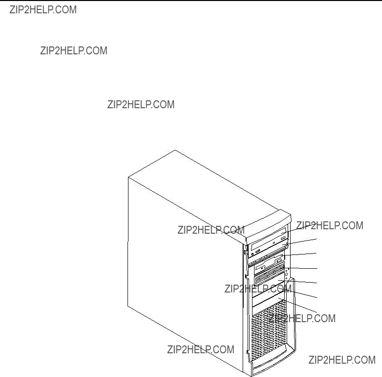
Server controls and indicators
This section identifies the controls and indicators on the front of your server.
CD-ROM eject button
CD-ROM drive activity light
Diskette-eject button
Diskette drive activity light
SCSI activity light
Power-on light
Power-control button
System error light
CD-ROM eject button: Press this button to release a CD from the drive.
CD-ROM drive activity light: When this light is on, it indicates that the CD-ROM drive is in use.
Diskette-eject button: Press this button to release a diskette from the drive.
Diskette-drive activity light: When this light is on, it indicates that the diskette drive is in use.
SCSI activity light: When this green light is flashing, the controller is accessing a SCSI device; for example, a hard disk drive.
Note: Hot-swap hard disk drives also have an activity light. This light is also known as the SCSI hard disk drive activity light.
If your server has a ServeRAID??? controller and this light flashes slowly (one flash per second), the drive is being rebuilt. When the light flashes rapidly (three flashes per second), the controller is identifying the drive.
Power-on light: When this green light is on, system power is present in the server.
Power-control button: Press this button to manually turn the server on or off.
System error light: When this amber light is on, it indicates that a system error has occurred. An amber error light on the interior of the server, adjacent to the faulty component, will also be on to further isolate the error. (For more information, see ???Chapter 6. Solving problems,??? on page 73.)
Chapter 1. Introducing the IBM xSeries 220 5
Cover-release latch: Slide this lever to release the cover.
Key lock:Use the key that comes with your server to unlock the cover.
Cover-release latch
Key lock
6 IBM?? xSeries 220 User???s Reference
Turning on the server
Turning on the server refers to the act of plugging the power cord of your server into the power source and starting the operating system.
After you plug the power cord of your server into the power supply and an electrical outlet, the server can start in any of the following ways:
???You can press the power-control button on the front of the server to start the server.
Notes:
1.You can install a circular disk over the power-control button to prevent accidental manual power-off. This disk, known as the power-control button shield, comes with your server.
2.After you plug the power cord of your server into an electrical outlet, wait approximately 20 seconds before pressing the power-control button. During this time, the system is initializing; therefore, the power-control button does not respond.
???If the server is turned on and a power failure occurs, the server will start automatically when power is restored.
???The Wake on LAN feature will turn on the server at the set time (when a Magic Packet is received), provided that all of the following conditions are met:
???AC power is present.
???The server is either off or shut down from an Advanced Configuration and Power Interface (ACPI) operating system.
???The Wake on LAN feature is enabled in the Configuration/Setup Utility program.
???The Wake on LAN adapter is installed in PCI slot 1 and is connected to the system board with the 3-pin auxiliary power connector.
Notes:
1.See ???Choices available from the Configuration/Setup main menu??? on page 12 for a description of the Configuration/Setup Utility program.
2.See ???System-board option connectors??? on page 28 for connector locations.
3.For additional information on the Wake on LAN function, adapters, and cables, refer to the documentation that comes with the adapters.
4.See ???Ethernet port??? on page 69 for information on Ethernet controllers and adapters, and Wake on LAN adapters.
???If the optional system-management adapter is installed in your server, the system-management adapter can turn on the server.
Chapter 1. Introducing the IBM xSeries 220 7
Turning off the server
Turning off the server refers to the act of disconnecting the server from the power source.
You can turn off the server in any of the following ways:
Statement 5
CAUTION:
The power control button on the device and the power switch on the power supply do not turn off the electrical current supplied to the device. The device also might have more than one power cord. To remove all electrical current from the device, ensure that all power cords are disconnected from the power source.
2 

 1
1 


???You can press the power-control button on the top of the server. This starts an orderly shutdown of the operating system, if this feature is supported by your operating system.
Note: After turning off the server, wait at least five seconds before you press the power-control button to turn on the server again.
???You might need to press and hold the power-control button for more than four seconds to cause an immediate shutdown of the server and to force the power off. You can use this feature if the operating system stops functioning.
???You can disconnect the server power cords from the electrical outlets to shut off all power to the server.
Note: After disconnecting the power cords, wait approximately 15 seconds for your system to stop running. Watch for the power-on light to stop blinking.
8 IBM?? xSeries 220 User???s Reference

Chapter 2. Arranging your workspace
To get the most from your server, arrange both the equipment you use and your work area to suit your needs and the kind of work you do. Your comfort is of foremost importance, but light sources, air circulation, and the location of electrical outlets also can affect the way you arrange your workspace.
Comfort
Although no single working position is ideal for everyone, here are a few guidelines to help you find a position that suits you best.
Sitting in the same position for a long time can cause fatigue. A good chair can make a big difference. The backrest and seat should adjust independently and provide good support. The seat should have a curved front to relieve pressure on the thighs. Adjust the seat so that your thighs are parallel to the floor and your feet are either flat on the floor or on a footrest.
When using the keyboard, keep your forearms parallel to the floor and your wrists in a neutral, comfortable position. Try to keep a light touch on the keyboard and your hands and fingers relaxed. You can change the angle of the keyboard for maximum comfort by adjusting the position of the keyboard feet.
Adjust the monitor so the top of the screen is at, or slightly below, eye level. Place the monitor at a comfortable viewing distance, usually 51 to 61 cm (20 to 24 in.), and position it so you can view it without having to twist your body. Also position other equipment you use regularly, such as the telephone or a mouse, within easy reach.
Glare and lighting
Position the monitor to minimize glare and reflections from overhead lights, windows, and other light sources. Even reflected light from shiny surfaces can cause annoying reflections on your monitor screen. Place the monitor at right angles to windows and other light sources, when possible. Reduce overhead lighting, if necessary, by turning off lights or using lower wattage bulbs. If you install the monitor near a window, use curtains or blinds to block the sunlight. You might have to adjust the Brightness and Contrast controls on the monitor as the room lighting changes throughout the day.
Where it is impossible to avoid reflections or to adjust the lighting, an antiglare filter placed over the screen might be helpful. However, these filters might affect the clarity of the image on the screen; try them only after you have tried all other methods of reducing glare.
Dust buildup compounds problems that are associated with glare. Remember to clean your monitor screen periodically using a soft cloth that is moistened with a nonabrasive liquid glass cleaner.
Air circulation
Your server and monitor produce heat. Your server has one or more fans that pull in fresh air and force out hot air. The monitor lets hot air escape through vents. Blocking the air vents can cause overheating, which might result in a malfunction or damage.
Place the server and monitor so that nothing blocks the air vents; usually, 15 cm (6 inches) of air space is sufficient. Also, make sure that the vented air is not blowing on someone else.
Electrical outlets and cable lengths
The location of electrical outlets and the length of power cords and cables that connect to the monitor, printer, and other devices might determine the final placement of your server.
When arranging your workspace:
???Avoid the use of extension cords. When possible, plug the server power cords directly into electrical outlets.
???Keep power cords and cables neatly routed away from walkways and other areas where they might get kicked accidentally.
For more information about power cords, refer to the power cord information in this on-line publication.
10 IBM?? xSeries 220 User???s Reference

Chapter 3. Configuring your server
The following configuration programs are provided with your server:
???Configuration/Setup Utility
This program is part of the basic input/output system (BIOS) code that comes with your server. You can use this program to configure serial and parallel port assignments, change interrupt request (IRQ) settings, change the drive startup sequence, set the date and time, and set passwords. See ???Using the Configuration/Setup Utility program??? for more information.
???SCSISelect Utility
With the built-in SCSISelect Utility program, you can configure the devices that are attached to the integrated SCSI controller. See ???Using the SCSISelect Utility program??? on page 17 for more information.
???PXE Boot Agent Utility
The Preboot eXecution Environment (PXE) Boot Agent Utility program is part of the BIOS code that comes with your server. You can use this program to change network startup (boot) protocols and startup (boot) order, to select operating system wake up support, and to set menu wait times. See ???Using the PXE Boot Agent Utility program??? on page 19 for more information.
???ServerGuide CDs
The ServerGuide CDs include software setup and installation tools that are specifically designed for IBM xSeries servers. You can use these CDs during the initial installation of your server to configure the server hardware and simplify your network operating system installation. The ServerGuide CDs also contain a collection of application programs, which you can install after your server is up and running. See ???Chapter 4. Using the ServerGuide CDs,??? on page 21 for more detailed information.
???ServeRAID programs
The ServeRAID programs come with the optional ServeRAID adapters. If your server has a ServeRAID adapter installed, you must use the ServeRAID Configuration program to define and configure your disk-array subsystem before you install your operating system.
Using the Configuration/Setup Utility program
This section provides instructions for starting the Configuration/Setup Utility program and descriptions of the menu choices that are available.
Starting the Configuration/Setup Utility program
To start the Configuration/Setup Utility program, do the following:
1.Turn on the server and watch the monitor screen.
2.When the message Press F1 for Configuration/Setup appears, press F1.
Notes:
a.You can set an administrator password through the Configuration/Setup Utility program only if the optional system-management adapter is installed in your server.
b.If you have set both levels of passwords (user and administrator), you must type the administrator password to access the full Configuration/Setup Utility menu.
3.Follow the instructions that appear on the screen.
Choices available from the Configuration/Setup main menu
From the Configuration/Setup Utility main menu, you can select settings that you want to change. The Configuration/Setup Utility main menu is similar to the following:
IBM - ?? IBM Corporation 2000
Configuration/Setup Utility
???System Summary
???System Information
???Devices and I/O Ports
???Date and Time
???System Security
???Start Options
???Advanced Setup
???Error Logs
Save Settings Restore Settings Load Default Settings
Exit Setup
Notes:
1.You can press F1 to display help information for a selected menu item.
2.The choices on some menus might differ slightly from the ones that are described in this book, depending on the BIOS version in your server.
Descriptions of the choices that are available from the main menu are as follows:
???System Summary
Select this choice to display configuration information. This includes the type and speed of the microprocessors and the amount of memory that is installed.
Changes that you make to configuration settings appear on this summary screen. You cannot edit the fields.
This choice appears on both the full and limited Configuration/Setup Utility menus.
???System Information
Select this choice to display information about your server. Changes that you make on other menus might appear on this summary screen. You cannot edit any fields. The System Information choice appears only on the full
12 IBM?? xSeries 220 User???s Reference
Configuration/Setup Utility main menu.
???Product Data
Select this choice to view system information, such as the machine type and model, the server serial number, and the revision level or issue date of the BIOS that is stored in the flash electrically erasable programmable ROM (EEPROM).
???Devices and I/O Ports
Select this choice to view or change the assignments for devices and input/output ports. This choice appears only on the full Configuration/Setup Utility main menu.
???Date and Time
Select this choice to set the system date and time.
The system time is in a 24-hour format (hour:minute:second).
???System Security
Select this choice to set passwords. This choice appears only on the full Configuration/Setup Utility main menu.
You can implement two levels of password protection:
???Power-on Password
Select this choice to set or change a power-on password. See ???Using passwords??? on page 15 for more information.
???Administrator Password
Note: This choice is available on the Configuration/Setup Utility menu only if the optional system-management adapter is installed in your server.
Select this choice to set or change an administrator password.
Attention: If an administrator password is set and then forgotten, it cannot be overridden or removed. You must replace the system board.
The administrator password provides access to all choices on the Configuration/Setup Utility main menu. You can set, change, or delete both the administrator and power-on passwords, and allow a power-on password to be changed by the user.
See ???Using passwords??? on page 15 for more information.
???Start Options
Select this choice to view or change the start options. Start options take effect when you start your server.
You can select keyboard operating characteristics, such as the keyboard speed. You also can specify whether the server starts with the keyboard number lock on or off, and you can enable the server to run without a diskette drive, monitor, or keyboard.
The server uses a startup sequence to determine the device from which the operating system starts. For example, you can define a startup sequence that checks for a startable diskette in the diskette drive, then checks the hard disk drive in bay 1, and then checks a network adapter.
If you have the appropriate Ethernet adapter and Wake on LAN software installed and enabled in the server, the server uses the alternative startup sequence instead of the primary startup sequence. The default for Wake on LAN is Disabled.
If the Boot Fail Count choice is enabled, you can restore the BIOS system defaults after three consecutive boot failures. If this choice is disabled, the BIOS system
Chapter 3. Configuring your server 13
defaults can only be loaded from the Configuration/Setup Utility main menu.
You can enable a virus-detection test that checks for changes in the master boot record at startup. You also can select to run POST in the enhanced mode or the quick mode.
???Advanced Setup
Select this choice to change values for advanced hardware features, such as cache control and PCI configuration.
A message appears above the choices on this menu to alert you that the system might malfunction if these options are configured incorrectly. Follow the instructions on the screen carefully.
???Processor Serial Number Access
Select this choice to specify whether the microprocessor serial number in the microprocessor is readable.
???System Partition Visibility
Select this choice to specify whether the System Partition is visible. To make the System Partition visible, set this value to Visible. To make the System Partition invisible, set this value to Hidden. See ???Chapter 4. Using the ServerGuide CDs,??? on page 21 for additional information on the System Partition.
???Core Chipset Control
Select this choice to modify settings that control features of the core chip set on the system board.
Attention: Do not make changes in this option unless directed to do so by an IBM authorized service representative.
???Cache Control
Select this choice to enable or disable the microprocessor cache. In addition, you can define the microprocessor cache type as write-back (WB) or write- through (WT). Selecting write-back mode provides better system performance.
???Memory Settings
Select this choice to manually disable or enable a bank of memory.
If a memory error is detected during POST or memory configuration, the server can automatically disable the failing memory bank and continue operating with reduced memory capacity. If this occurs, you must manually enable the memory bank after the problem is corrected. Select Memory Settings from the Advanced Setup menu, use the arrow keys to highlight the bank that you want to enable; then, use the arrow keys to select Enable.
Note: If a memory error is detected during normal operation, System Management Interrupt (SMI) can disable the memory.
???PCI Bus Control
Note: If the optional system-management adapter is installed in your server, this feature is disabled; in this case, the PCI Bus Control choice is not available on the Configuration/Setup Utility menu.
Select this choice to assign IRQs and program the master latency timer.
???PCI Slot/Device Information
Note: This choice is available on the Configuration/Setup Utility menu only if the optional system-management adapter is installed in your server.
Select this choice to view and identify system resources that are used by PCI devices. PCI devices automatically communicate with the server
14 IBM?? xSeries 220 User???s Reference
configuration information. This usually results in automatic configuration of a PCI device.
Attention: You must use the menu selections to save custom settings for the PCI Slot/Device Information choice. The Save Settings, Restore Settings, and Load Default Settings choices on the main menu of the Configuration/Setup Utility do not save the PCI Slot/Device Information settings.
After making changes, select:
???Save and exit the PCI Utility to save the changes and return to the Advanced Setup choice.
???Exit the PCI Utility without saving changes to discard the changes, retain the current settings, and return to the Advanced Setup choice.
???Error Log
Select this choice to view or clear error logs.
???Select POST Error Log to view the three most recent error codes and messages that the system generated during POST.
???Select Clear error logs to clear the error logs.
???Save Settings
Select this choice to save your customized settings.
???Restore Settings
Select this choice to discard your changes and retain the current settings.
???Load Default Settings
Select this choice to discard your changes and restore the factory settings.
???Exit Setup
If you have made any changes, the program will prompt you to save the changes or exit without saving the changes.
Using passwords
The System Security choice appears only on the full Configuration/Setup Utility menu. After you select this choice, you can implement two levels of password protection: power-on password and administrator password.
Power-on password
Select this choice to set a power-on password.
You can use any combination of up to seven characters (A???Z, a???z, and 0???9) for your power-on password. Keep a record of your password in a secure place. If you forget the power-on password, you can regain access to the server through one of the following methods:
???If an administrator password has been set, enter the administrator password at the power-on prompt. (If necessary, see ???Administrator password??? on page 16 for details.) Start the Configuration/Setup Utility program and change the power-on password.
???Start the Configuration/Setup Utility program, and change the power-on password.
???Change the position of the password-override switch as described in ???Setting the password-override switch???.
Chapter 3. Configuring your server 15
???Remove the battery and then reinstall the battery.
Setting the password-override switch: The following illustration shows the location of the password-override switch (switch 8, which is the switch farthest to the right, on switch block 1) on the system board.
Power-on password-override switch (switch 8 of switch block 1)
To set the password-override switch, do the following:
1.Review the information in ???Before you begin??? on page 31.
2.Turn off the server and peripheral devices and disconnect all external cables and power cords; then, remove the cover. See ???Removing the side cover??? on page 38.
3.Change the setting of the password-override switch (switch 8 on switch block 1 on the system board) to the opposite side of the switch. This bypasses the power- on password.
4.Install the server cover (see ???Installing the side cover??? on page 60) and connect all external cables and power cords.
5.Restart the server.
Notes:
1.If you want the server to prompt for a password when you turn it on, you can start the Configuration/Setup Utility program and set the power-on password.
2.Changing the position of the password-override switch does not affect the administrator password check if an administrator password has been set.
Administrator password
Note: This choice is available on the Configuration/Setup Utility menu only if the optional system-management adapter is installed in your server.
Select this choice to set an administrator password. The administrator password provides access to all choices on the Configuration/Setup Utility main menu. You can set, change, or delete both the administrator and power-on passwords, and allow a power-on password to be changed by the user.
Attention: If an administrator password is set and then forgotten, it cannot be overridden or removed. You must replace the system board.
The following table provides a summary of the password features.
16 IBM?? xSeries 220 User???s Reference

Table 2. Power-on and administrator password features
Using the SCSISelect Utility program
SCSISelect is a built-in, menu-driven configuration utility program that you can use to:
???View the default SCSI IDs
???Locate and correct configuration conflicts
The following sections provide instructions for starting the SCSISelect Utility and descriptions of the menu choices that are available.
Note: If your server has a RAID adapter installed, use the configuration method that is supplied with the RAID adapter to view or change SCSI settings for devices attached to the adapter.
Starting the SCSISelect Utility program
Complete the following steps to start the SCSISelect Utility program:
1.Turn on the server.
2.When the <<< Press <CTRL><A> for SCSISelect??? Utility! >>> prompt appears, press Ctrl+A.
3. When the Would you like to configure the host adapter or run the SCSI disk utility? question appears, make your selection and press Enter.
4.Use the arrow keys to select a choice from the menu:
???Press Esc to return to the previous menu.
???Press the F5 key to switch between color and monochrome modes (if your monitor permits).
Chapter 3. Configuring your server 17
5.Follow the instructions on the screen to change the settings of the selected items; then, press Enter.
Choices available from the SCSISelect menu
The following choices appear on the SCSISelect Utility menu:
???Configure/View Host Adapter Settings
Select this choice to view or change the SCSI controller settings. To reset the SCSI controller to its default values, press F6; then, follow the on-screen instructions.
You can view or change the following controller settings:
???Host Adapter SCSI ID
Select this choice to view the SCSI controller ID, which is usually 7.
???SCSI Parity Checking
Select this choice to view the assigned value of Enabled.
???Host Adapter SCSI Termination
Select this choice to view the assigned value of Enabled.
???Boot Device Options
Select this choice to configure startable-device parameters. Before you can make updates, you must know the ID of the device whose parameters you want to configure.
???SCSI Device Configuration
Select this choice to configure SCSI-device parameters. Before you can make updates, you must know the ID of the device whose parameters you want to configure.
Note: The Maximum Sync Transfer Rate is the transfer rate for Ultra SCSI devices.
???The transfer rate for Ultra160 LVD devices is 160.0 Mbps.
???The transfer rate for Ultra2 SCSI LVD devices is 80.0 Mbps.
???The transfer rate for Fast SCSI devices is 20.0 Mbps.
???Advanced Configuration Options
Select this choice to view or change the settings for advanced configuration options. These options include enabling support for large hard disk drives and support for drives with UltraSCSI speeds.
???SCSI Disk Utilities
Select this choice to view the SCSI IDs that are assigned to each device or to format a SCSI device.
To use the utility program, select a drive from the list. Read the screens carefully before making a selection.
Note: If you press Ctrl+A before the selected drives are ready, an Unexpected SCSI Command Failure screen might appear. Restart the server and watch the SCSISelect messages as each drive starts. After the drive that you want to view or format starts, press Ctrl+A.
18 IBM?? xSeries 220 User???s Reference

Using the PXE Boot Agent Utility program
The Preboot eXecution Environment (PXE) Boot Agent is a built-in, menu-driven configuration utility program that you can use to:
???Change network startup (boot) protocols
???Change network startup (boot) order
???Set menu wait times
???Select operating system wake up support
Starting the PXE Boot Agent Utility program
The following sections provide the instructions needed to start the PXE Boot Agent Utility and descriptions of the available menu choices.
To start the PXE Boot Agent Utility program, do the following:
1.Turn on the server.
2.When the <Initializing Intel (R) Boot Agent version X.X.XX PXE 2.0 Build XXX (WfM 2.0) prompt appears, press Ctrl+S.
Note: By default, you will have two seconds after the prompt appears on the screen to press Ctrl+S.
3.Use the arrow keys or press Enter to select a choice from the menu:
???Press Esc to return to the previous menu.
???Press the F4 key to exit.
4.Follow the instructions on the screen to change the settings of the selected items; then, press Enter.
Choices available from the PXE Boot Agent menu
The following choices appear on the PXE Boot Agent Utility menu:
???Network Boot Protocol
PXE is the default value for this menu item.
Note: Do not change this value. There are no other network boot protocols supported.
???Boot Order
Select this choice to change the order in which boot devices are queried.
???Try local drives first, then network (default)
???Try network only
???Try local drives only
???Try network first, then local drives
???Show setup prompt
Select this choice to either display the PXE setup prompt or disable it. Disable is the default setting.
When this choice is enabled, Press Ctrl+S to enter the setup menu will appear on the screen under the initializing prompt.
Chapter 3. Configuring your server 19
???Setup time wait menu
Select this choice to set the amount of time (in seconds) that the system will pause during initialization for a Ctrl+S input.
???2 seconds (default)
???3 seconds
???5 seconds
???8 seconds
???Legacy OS wake up support
Select this choice to allow/disallow a non-windows operating system to use adapter remote wake up capability.
???Disabled (default)
???Enabled
20 IBM?? xSeries 220 User???s Reference

Chapter 4. Using the ServerGuide CDs
The ServerGuide CDs include easy-to-use software setup and installation tools that are specifically designed for your IBM server. The ServerGuide Setup and Installation program detects the server model and hardware options that are installed and uses that information during setup to configure the hardware. The ServerGuide tools simplify NOS installations by providing updated device drivers, and in some cases, installing them automatically.
If a newer version of the ServerGuide software is available, you can purchase an update package. For details, see the ServerGuide Updates form that comes with your server library, or go to the ServerGuide fulfillment Web site at http://www.ibm.com/pc/coupon
The ServerGuide software has these features to make setup easier:
???An easy-to-use interface with online help
???Diskette-free setup, and configuration programs that are based on detected hardware
???Performance Optimizer program, which easily tunes your server for your environment
???A system BIOS update program, which updates the BIOS directly from the CD
???Device drivers that are provided for your server model and detected hardware
???NOS partition size and file-system type that are selectable during setup
???Powerful application programs and administration tools
Features at a glance
The following is a summary of ServerGuide features.
Note: Exact features and functions can vary with different versions of the ServerGuide software. To learn more about the version you that have, start the Setup and Installation CD and view the online Overview.

Setup and Installation CD
Note: The ServerGuide program requires a supported IBM server with an enabled startable (bootable) CD- ROM drive. Not all features are supported on all models.
???Sets system date and time.
???Detects the ServeRAID adapter or controller and runs the ServeRAID configuration program.
???Updates the licensed internal code (firmware) level without creating diskettes.
???Checks the system BIOS level to determine whether a later level is available from the CD. You can update BIOS without creating diskettes.
???Updates firmware for system management adapters and controllers.
???Provides the Performance Optimizer program to easily tune your server for your environment.
???Creates a System Partition on the default drive. You can run server-specific utility programs after setup.
???Detects installed hardware options and provides updated device drivers for most adapters and devices.
Setup and Installation CD
(continued)
???Creates a Setup Replication Diskette for replicating setup selections for other servers of the same model.
???Provides diskette-free installation for Windows 2000, Windows NT, and NetWare operating systems.
???Provides a replicated installation path for multiple Windows 2000, Windows NT Server 4.0, and Windows Enterprise Edition, and Red Hat Linux.
???Includes an online README file with links to tips for your hard-ware and NOS installation.
Note: Installation requires your
NOS CD.
System Updates and Applications CD
???Creates diagnostic, RAID, device driver, and other support diskettes from the CD; or with an Internet connection, you can check for an update from a dedicated IBM file transfer protocol (FTP) server.
???Installs some updates without requiring diskettes. Where applicable, you can run executable files directly from the CD or unzip files to any drive on your server or another server on your network.
System Updates and Applications CD
(continued)
???Includes a vast library of fully tested device drivers for your server.
???Includes a search function to help you locate updates by title or keywords.
???Installs powerful applications directly from the CD. See the CD label for a current list of applications.
Setup and configuration overview
When you use the Setup and Installation CD, you do not need setup diskettes. You can use the CD to configure any supported IBM server model. The setup program checks your system BIOS, service processors, and other system hardware to determine if system updates are available. The setup program provides a list of tasks that are required to set up your server model. On RAID servers, you can run the ServeRAID Manager program to create logical drives.
Note: Exact features and functions can vary with different versions of the
ServerGuide software.
When you start the Setup and Installation CD, the following happens:
???You are prompted for your language, country, and keyboard layout. (This information is stored and later passed on to the NOS installation program.)
22 IBM?? xSeries 220 User???s Reference

???ServerGuide displays choices for running the configuration programs. For example:
???The Express Configuration method runs the required programs for your server, based on the hardware that is detected.
???The Custom Configuration method displays all programs that are available for your server, and you decide which programs to run.
???The Replicated Configuration method provides the option of duplicating your setup selections to other servers that are the same xSeries 220 model.
???If you select the Custom Configuration method, the following programs are optional. If you select the Express Configuration method, some or all of these programs are run, depending on the hardware that is detected.
???The Set Date and Time feature is provided so that you do not have to use the Configuration/Setup Utility program to access these settings.
???ServerGuide checks the server BIOS and microcode (firmware) levels for supported options and then checks the CD for a newer level. CD content can be newer than the hardware. ServerGuide can perform a flash update of the BIOS.
???The ServeRAID configuration program starts, leading you through the entire configuration process.
???The Performance Optimizer program easily tunes your server for your environment.
???ServerGuide creates a System Partition on the default drive.
???ServerGuide displays a confirmation summary, so that you will know when you have completed all the required tasks. Then, you are ready to install your NOS.
Notes:
1.Plug and Play adapters are configured automatically. Non-Plug and Play adapters or non-IBM adapters might require switch settings, additional device drivers, and installation after the NOS is installed. See the documentation that comes with the adapter.
2.Diagnostics for your server come on a separate diagnostics CD.
System Partition
ServerGuide creates a 50 MB System Partition on the default drive. The System Partition contains server-specific utility programs such as service processor disk operating system (DOS) utilities, system diagnostics, flash BIOS updates, and other programs.
Note: Programs in the System Partition vary by server model, and not all server models run utility programs from the System Partition. To determine which ones do, start the Setup and Installation CD and view the online Overview.
After setup is complete, you can access programs in the System Partition by restarting the server and pressing Alt+F1 when the prompt is displayed. The System Partition menu displays the programs that are available on your server model.
Typical NOS installation
You can use ServerGuide to shorten your installation time. ServerGuide provides the necessary device drivers, based on the hardware that you have and the NOS that you are installing. The following is a brief explanation of a typical ServerGuide NOS installation.
Chapter 4. Using the ServerGuide CDs 23
Note: Exact features and functions can vary with different versions of the
ServerGuide software.
???After you have completed the setup process, the operating system installation program starts. (You will need your copy of the NOS CD to complete the installation.)
???ServerGuide stores information about the server model, service processor, hard disk controllers, and network adapters. It then checks the CD for newer device drivers. This information is stored and then passed to the NOS installation program.
???With some NOS installations, you can create a NOS Replication Diskette for setting up additional servers. The diskette will contain the Internet protocol (IP) address, server name, and other selections.
???ServerGuide presents NOS partition options that are based on your NOS selection and the installed hard disk drives.
???If you are installing the NOS from diskette, ServerGuide displays the required diskettes that you must create, and the optional diskettes that you might want to create. The diskettes that you can create are the device driver diskettes for the installed adapters or controllers.
ServerGuide prompts you to insert your NOS CD and restart the server. At this point, the installation program for the NOS (for example, Microsoft Windows 2000) takes control to complete the installation.
Setting up or updating multiple servers
You can use ServerGuide to create diskettes that help you set up or update multiple servers. You can modify information on the diskettes as you use them to set up or update other servers.
Note: Availability and function can vary by server model and by the hardware that is installed.
You can create a Setup Replication Diskette, which contains your hardware configuration selections. Use this diskette to replicate selections to other servers that are of the same model.
You can create a NOS Replication Diskette, which contains your server name, domain name, and other information that you need to complete multiple installations. This feature supports systems running Windows 2000, Windows NT Server 4.0, and Red Hat Linux.
Installing your NOS without ServerGuide
If you have already configured the server hardware and you decide not to use ServerGuide to install your NOS, download the latest NOS installation instructions:
1.Go to http://www.ibm.com/pc/support
2.Click Servers.
3.From the Family field, select your server model.
4.Click Software information. The available installation instructions are listed.
24 IBM?? xSeries 220 User???s Reference
Additional programs included with ServerGuide
As a convenience, ServerGuide comes with additional software to assist you with the server installation.
A variety of powerful applications are included with ServerGuide. Offerings can vary with the different versions of the ServerGuide software. Check the application CD labels for a list of applications, or start the Setup and Installation CD and view the online Overview.
Error symptoms
This section provides ServerGuide error symptoms and probable solutions.
Chapter 4. Using the ServerGuide CDs 25
26 IBM?? xSeries 220 User???s Reference
Chapter 5. Installing options
This chapter provides instructions to help you add options to your server. Some option-removal instructions are provided, in case you need to remove one option to install another. For a list of supported options for your server, see the ServerProven list at:
http://www.ibm.com/pc/compat/
Major components of the xSeries 220 server
Note: The illustrations in this document might differ slightly from your hardware.
The following illustration shows the locations of major components in your server.
Filler
panels
Memory modules
Drive cage
Front adapter support bracket
Support bracket assembly
Cover
System board
The illustrations in the following sections show the components on the system board.
System-board option connectors
The following illustration identifies system-board connectors for user-installable options.
DIMM 1
(J19)
DIMM 2
(J21)
DIMM 3 (J23)
DIMM 4 (J26)
PCI 1 (J29) PCI 2 (J31)
Battery (BH1)
Notes:
1.If your server and operating system support system-management functions and, if the optional system-management adapter is installed in your server, the system- management connector (J32) is dedicated for use by the system-management adapter.
2.The system-management adapter is also known as the service processor.
28 IBM?? xSeries 220 User???s Reference
System-board internal cable connectors
The following illustration identifies system-board connectors for internal cables.
System-board external port connectors
The following illustration identifies the external port connectors on the rear of the server.
Keyboard/mouse
USB
Serial A
Parallel
Serial B
Ethernet
Video
Note: For information on adding external SCSI devices to your server, see ???SCSI cabling requirements??? on page 67.
Chapter 5. Installing options 29
System-board jumpers and switches
The following illustration identifies the jumpers and switches on the system board.
Switch block
Flash ROM page-swap jumper (J38)
System-board jumper blocks
Any jumper blocks on the system board that are not shown in the illustration are reserved. For normal operation of the system, no jumpers should be installed on any of the jumper blocks. See ???Recovering the BIOS code??? on page 97 for information about the flash ROM page-swap jumper.
System-board switch block
The switch block contains microswitches 1 through 8. As pictured in this illustration, switch 8 is at the right of the switch block, and switch 1 is at the left.
The following table describes the function for each switch. The default setting is Off for all switches in the switch block.
Table 3. Switches 1 through 8
30 IBM?? xSeries 220 User???s Reference

Before you begin
Before you begin to install options in your server, read the following information:
???Become familiar with the safety and handling guidelines under ???Handling static-sensitive devices???, and read the safety statements in ???Safety information??? on page 32. These guidelines will help you work safely while working with your server or options.
???Make sure that you have an adequate number of properly grounded electrical outlets for your server, monitor, and any other options that you intend to install.
???Back up all important data before you make changes to disk drives.
???Have a small, flat-blade screwdriver available.
???For a list of supported options for your server, refer to http://www.ibm.com/pc/compat on the World Wide Web.
System reliability considerations
To help ensure proper cooling and system reliability, make sure that:
???Each of the drive bays has either a drive or a filler panel installed.
???The cover is in place during normal operation, or is removed for no longer than 30 minutes while the server is operating.
???There is space around the server to allow the server cooling system to work properly. Leave about 127 mm (5 in.) of space around the front and rear of the server.
???Cables for optional adapters are routed according to the instructions that are provided with the adapters.
???A failed fan is replaced within one hour.
Handling static-sensitive devices
Attention: Static electricity can damage electronic devices and your system. To avoid damage, keep static-sensitive devices in their static-protective bag until you are ready to install them.
To reduce the possibility of electrostatic discharge, observe the following precautions:
???Limit your movement. Movement can cause static electricity to build up around you.
???Handle the device carefully, holding it by its edges or its frame.
???Do not touch solder joints, pins, or exposed printed circuitry.
???Do not leave the device where others can handle and possibly damage the device.
???While the device is still in its anti-static package, touch it to an unpainted metal part of the system unit for at least two seconds. (This drains static electricity from the package and from your body.)
???Remove the device from its package and install it directly into your system unit without setting it down. If it is necessary to set the device down, place it on its static-protective package. (If your device is an adapter, place it component side up.) Do not place the device on your system unit cover or on a metal table.
???Take additional care when handling devices during cold weather, as heating reduces indoor humidity and increases static electricity.
Chapter 5. Installing options 31
Safety information
Before installing this product, read the Safety Information book.
Antes de instalar este produto, leia o Manual de Informa????es sobre Seguran??a.
Pred instalac?? tohoto produktu si prectete pr??rucku bezpecnostn??ch instrukc??.
L??s h??ftet med sikkerhedsforskrifter, f??r du installerer dette produkt.
Lue Safety Information -kirjanen, ennen kuin asennat t??m??n tuotteen.
Avant de proc??der ?? l'installation de ce produit, lisez le manuel Safety Information.
Vor Beginn der Installation die Brosch??re mit Sicherheitshinweisen lesen.
Przed zainstalowaniem tego produktu nale??y przeczyta?? broszur?? Informacje Dotycz??ce Bezpiecze??stwa.
Prima di installare questo prodotto, leggere l'opuscolo contenente le informazioni sulla sicurezza.
Lees voordat u dit product installeert eerst het boekje met veiligheidsvoorschriften.
32 IBM?? xSeries 220 User???s Reference
Les heftet om sikkerhetsinformasjon (Safety Information) f??r du installerer dette produktet.
Antes de instalar este produto, leia o folheto Informa????es sobre Seguran??a.
?????????? ???????????????????? ???????????????? ???????????????? ?????????????? ???? ?????????????? ???????????????????????? (Safety Information).
Pred in??tal?? ciou tohto produktu si pre ??tajte Informa n?? bro?? ?? rku o bezpe nosti.
Preden namestite ta izdelek, preberite knji??ico Varnostne informacije.
Antes de instalar este producto, lea la Informaci??n de Seguridad.
L??s s??kerhetsinformationen innan du installerar den h??r produkten.
Install?? l?? s el tt olvassa el a Biztons?? gi el ??r?? sok k??zik?? nyv??t !
Chapter 5. Installing options 33
Statement 1
Danger
Electrical current from power, telephone, and communication cables is hazardous.
To avoid a shock hazard:
???Do not connect or disconnect any cables or perform installation, maintenance, or reconfiguration of this product during an electrical storm.
???Connect all power cords to a properly wired and grounded electrical outlet.
???Connect to properly wired outlets any equipment that will be attached to this product.
???When possible, use one hand only to connect or disconnect signal cables.
???Never turn on any equipment when there is evidence of fire, water, or structural damage.
???Disconnect the attached power cords, telecommunications systems, networks, and modems before you open the device covers, unless instructed otherwise in the installation and configuration procedures.
???Connect and disconnect cables as described in the following table when installing, moving, or opening covers on this product or attached devices.
To connect:
1.Turn everything OFF.
2.First, attach all cables to devices.
3.Attach signal cables to connectors.
4.Attach power cords to outlets.
5.Turn device ON.
To disconnect:
1.Turn everything OFF.
2.First, remove power cords from outlets.
3.Remove signal cables from connectors.
4.Remove all cables from devices.
34 IBM?? xSeries 220 User???s Reference

Statement 2
CAUTION:
When replacing the lithium battery, use only IBM Part Number 33F8354 or an equivalent type battery recommended by the manufacturer. If your system has a module containing a lithium battery, replace it only with the same module type made by the same manufacturer. The battery contains lithium and can explode if not properly used, handled, or disposed of.
Do not:
???Throw or immerse into water.
???Heat to more than 100 C (212 F)
???Repair or disassemble
Dispose of the battery as required by local ordinances or regulations.
Statement 3
CAUTION:
When laser products (such as CD-ROMs, DVD drives, fiber optic devices, or transmitters) are installed, note the following:
???Do not remove the covers. Removing the covers of the laser product could result in exposure to hazardous laser radiation. There are no serviceable parts inside the device.
???Use of controls or adjustments or performance of procedures other than those specified herein might result in hazardous radiation exposure.
Danger
Some laser products contain an embedded Class 3A or Class 3B laser diode. Note the following. Laser radiation when open. Do not stare into the beam, do not view directly with optical instruments, and avoid direct exposure to the beam.
Chapter 5. Installing options 35
Statement 4
CAUTION:
Use safe practices when lifting.
Statement 5
CAUTION:
The power control button on the device and the power switch on the power supply do not turn off the electrical current supplied to the device. The device also might have more than one power cord. To remove all electrical current from the device, ensure that all power cords are disconnected from the power source.
2 

 1
1 


36 IBM?? xSeries 220 User???s Reference
Rotating the stabilizing feet
The feet attached to the bottom cover rotate 90 degrees to provide additional stability for your server.
Place the server in an upright position; then, rotate the feet a quarter turn away from the server. Carefully position the server on its feet.
When you need to access the inside of the server to install options, you might find it easier to place the server on its side, so that the system board is facing you. If you do so, rotate the feet in towards the server, so that they do not break off due to the weight of the server.
Chapter 5. Installing options 37
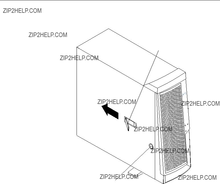
Removing the side cover
The following information describes how to remove the side cover.
Note: The illustrations in this document might differ slightly from your hardware.
Cover-release latch
Key lock
To remove the side cover from the server, do the following:
1.Review the information in ???Before you begin??? on page 31.
2.Turn off the server and all attached devices, and disconnect all external cables and power cords.
3.If necessary, unlock the server cover.
4.Pull out on the cover-release latch at the rear of the server; then, slide the cover toward the rear of the server and remove it.
Attention: For proper cooling and airflow, replace the cover before turning on the server. Operating the server for extended periods of time (over 30 minutes) with the cover removed might damage server components.
5.For a tower model, rotate the stabilizing feet on the bottom of the server, and place the server on its side to install or remove components.
38 IBM?? xSeries 220 User???s Reference

Removing the support bracket assembly
When working with some options such as hard disk drives and microprocessors, you must first remove the support bracket assembly to access the location of the option. The support bracket assembly consists of a support bracket, an air baffle, and a fan.
To remove the support bracket assembly, do the following:
1.Review the safety precautions in ???Safety information??? on page 32.
2.Turn off the server and peripheral devices and disconnect all external cables and power cords.
3.Remove the side cover (see ???Removing the side cover??? on page 38 for details).
4.If your server is a non-hot-swap model, continue with step 6.
5.If your server is a hot-swap model, press down on the latches on either side of connector J42, and remove the voltage regulator module (VRM) from connector J42. (See ???System-board option connectors??? on page 28 for connector locations.)
Note: Remember to reinstall this VRM after you reinstall the support bracket assembly.
6.Disconnect the fan cable (connector J10) from the system board. (See ???System- board internal cable connectors??? on page 29 for connector locations.)
Note: Remember to reconnect this cable after you reinstall the support bracket assembly.
7.Carefully pull up on the end of the support bracket assembly that is closer to the rear of the server; then, rotate and lift the support bracket assembly out of the server.
Chapter 5. Installing options 39
8. Store the support bracket assembly in a safe place.
Working with adapters
You can install up to five peripheral component interconnect (PCI) adapters in the PCI slots on the system board of your server. See the xSeries 220 ServerProven list at http://www.ibm.com/pc/compat/ for a list of PCI adapters that your server supports.
Your server comes with an integrated video controller on the system board. When you install a video adapter, the server BIOS code automatically disables the integrated video controller.
Note: The illustrations in this document might differ slightly from your hardware.
The following illustration shows the location of the 33 MHz PCI slots on the system board.
PCI slot 1 32-bit 33 MHz (J29)
PCI slot 2 32-bit 33 MHz (J31)
PCI slot 3 64-bit 33 MHz (J35)
PCI slot 4 64-bit 33 MHz (J39)
PCI slot 5 64-bit 33 MHz (J40)
Adapter considerations
Before you install adapters, review the following:
???Locate the documentation that comes with the adapter, and follow those instructions in addition to the instructions given in this chapter. If you need to change switch or jumper settings on your adapter, follow the instructions that come with the adapter.
???You can install full-length adapters in all PCI slots.
???You can install a 32-bit adapter in any of the PCI slots, but you might want to install it in a 32-bit slot and use the 64-bit slots for 64-bit adapters.
???Your server supports 5.0V and universal PCI adapters; it does not support 3.3V adapters.
???Your server uses a rotational interrupt technique to configure PCI adapters. Because of this technique, you can install a variety of PCI adapters that currently do not support sharing of PCI interrupts.
???The server has two PCI buses. PCI slots 1 and 2 are on PCI bus A, and PCI slots 3, 4, and 5 are on PCI bus B.
Note: PCI bus A is sometimes referred to as bus 0; PCI bus B is sometimes referred to as bus 1.
40 IBM?? xSeries 220 User???s Reference

The system scans PCI slots 1 through 5 to assign system resources; then, the system starts (boots) the PCI devices in the following order: PCI slots 1 and 2, system board SCSI devices, and then PCI slots 3 through 5.
???If you plan to use the Wake on LAN (WOL) function in the server, you must install a Wake on LAN-enabled NIC adapter in PCI slot 1, and install the Wake on LAN cable that comes with the Wake on LAN adapter to connect this adapter to the system board. You must use a Wake on LAN-enabled adapter as identified in the xSeries 220 ServerProven list at http://www.ibm.com/pc/compat/. Only PCI slot 1 supports a Wake on LAN-enabled adapter. For additional information on the Wake on LAN function, adapter, and cables, refer to the documentation that comes with the Wake on LAN adapter.
???If you plan to use the optional system-management adapter in the server, you must install the optional system-management adapter in PCI slot 2. Only PCI slot 2 supports the optional system-management adapter. For additional information on the optional system-management adapter, refer to the documentation that comes with the adapter.
Installing an adapter
Expansion-slot cover
Rear adapter
retainingAdapter bracket
Front adapter support bracket
Attention: When you handle electrostatic discharge (ESD) sensitive devices, take precautions to avoid damage from static electricity. For details on handling these devices, see ???Handling static-sensitive devices??? on page 31.
To install an adapter, do the following:
1.Review the safety precautions in Statement 1 and Statement 5 in ???Safety information??? on page 32.
2.Turn off the server and peripheral devices, and disconnect all external cables and power cords; then, remove the side cover. See ???Removing the side cover??? on page 38 for details.
Chapter 5. Installing options 41
3.Carefully remove the support bracket assembly from the server (see ???Removing the support bracket assembly??? on page 39). Store the cover and the support bracket assembly in a safe place.
4.Determine which PCI slot you will use for the adapter.
Note: Check the instructions that come with the adapter for any requirements or restrictions.
5.Remove the rear adapter retaining bracket from the server. If you are installing a full-length adapter, rotate the front adapter support bracket to the open (unlocked) position.
6.Remove the expansion-slot cover. Store it in a safe place for future use.
Attention: Expansion-slot covers must be installed on all vacant slots. This maintains the electronic emission characteristics of the system and ensures proper cooling of system components.
7.Refer to the documentation that comes with your adapter for any cabling instructions. It might be easier for you to route cables before you install the adapter.
8.Remove the adapter from the static-protective package.
Attention: Avoid touching the components and gold-edge connectors on the adapter.
9.Place the adapter, component-side up, on a flat, static-protective surface.
10.Set any jumpers or switches as described by the adapter manufacturer.
11.Install the adapter:
a.Carefully grasp the adapter by its top edge or upper corners, and align it with the expansion slot on the system board.
b.Press the adapter firmly into the expansion slot.
Attention: When you install an adapter in the server, be sure that it is completely and correctly seated in the system-board connector before you apply power. Incomplete insertion might cause damage to the system board or the adapter.
c.When the adapter is fully seated, release the front adapter support bracket by pushing inward on the latch. Make sure that the front adapter support bracket holds the adapter securely in place.
d.If you opened the front adapter support bracket, rotate it to the closed (locked) position; then, reinstall the rear adapter retaining bracket in the server.
42 IBM?? xSeries 220 User???s Reference
12.Connect any needed cables to the adapter.
Attention: Route cables so that they do not block the flow of air from the fans.
The following illustration shows how to reroute the SCSI cable. If you install a ServeRAID adapter and intend to use it with hot-swap hard disk drives, remove the cable from the internal SCSI connector (J41) on the system board and connect it to the ServeRAID adapter.
Note: You can also install a ServeRAID adapter in non-hot-swap models; however, non-hot-swap models do not support hot-swap hard disk drives.
SCSI cable
ServeRAID adapter
SCSI connector (J41)
13.If you have other options to install or remove, do so now; otherwise, replace the support bracket assembly; then, go to ???Installing the side cover??? on page 60.
Note: If your server is a hot-swap model, reinstall the VRM in connector J42 after you reinstall the support bracket assembly. (See ???System-board option connectors??? on page 28 for connector location.)
Chapter 5. Installing options 43
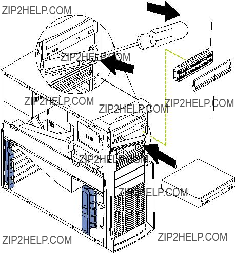
Installing internal drives
Different types of drives enable your system to read multiple types of media and store more data. Several types of drives are available, such as:
???Diskette (preinstalled)
???Hard disk (preinstalled on some models)
???CD-ROM (preinstalled)
???Tape
Internal drive bays
Internal drives are installed in bays. The bays of the xSeries 220 are in the front of the server, as shown in the following illustration.
Note: The illustrations in this document might differ slightly from your hardware.
Bay 1
Bay 2
Bay 3
Bay4
Bay 5
Bay 6
Bay 7
To remove or install a drive, you must turn off the server first, unless you are removing or installing a hot-swap hard disk drive. Diskette drives, tape drives, and CD-ROM drives are removable-media drives. You can install removable-media drives in bays 1, 2, 3, and 4. You can install SCSI hard disk drives in bays 4, 5, 6, and 7.
???Your server comes with a 3.5-inch, 1.44 MB diskette drive in bay 3, an integrated drive electronics (IDE) CD-ROM drive in bay 1, and a hard disk drive in bay 7 (in some models).
???The xSeries 220 server supports five 3.5-inch drives; however, the server supports only one diskette drive.
???The diskette drive uses 1 MB and 2 MB diskettes. For optimum use, format 1 MB diskettes to 720 KB and format 2 MB diskettes to 1.44 MB.
???The xSeries 220 server supports two 5.25-inch drives and four SCSI hard disk drives. The server does not support IDE hard disk drives. Some models support hot-swap hard disk drives. Other models support only non-hot-swap hard disk
44 IBM?? xSeries 220 User???s Reference
drives. Refer to the documentation that comes with your server for additional information.
Your server supports four 1-inch (26 mm) slim, 3.5-inch SCSI hard disk drives in the hard disk drive bays (4, 5, 6, and 7). You can install four non-hot-swap hard disk drives in the models that have the standard non-hot-swap drive cage. You can install three hot-swap hard disk drives and one non-hot-swap hard disk drive in the models that come with the hot-swap drive cage. Both the non-hot- swap and hot-swap drive cages hold a maximum of three hard disk drives. The drive cages comprise bays 5, 6, and 7.
???Bay 2 comes without a device installed. This bay is for a 5.25-inch, half-high, removable-media drive, such as a tape backup drive.
???Bay 4 is for a 3.5-inch, slim, removable-media drive or SCSI hard disk drive.
Note: The electromagnetic interference (EMI) integrity and cooling of the server are both protected by having bays 1 through 4 covered or occupied. When you install a drive, save the filler panel from the bay, in case you later remove the drive and do not replace it with another.
Preinstallation steps (all bays)
Before you install drives in your server, verify that you have all the cables and any other equipment specified in the documentation that comes with the drive. You might also need to perform certain preinstallation activities. Some of the steps are required only during the initial installation of an option.
1.Read ???Safety??? on page v, ???Handling static-sensitive devices??? on page 31, and the documentation that comes with your drive.
2.Choose the bay in which you want to install the drive.
3.Check the instructions that come with the drive to see if you need to set any switches or jumpers on the drive.
Chapter 5. Installing options 45
Installing a drive in bay 1, 2, 3, or 4
EMC shield
Filler panel
To install a drive in bay 1, 2, 3, or 4, do the following:
1.Read the information in ???Preinstallation steps (all bays)??? on page 45.
2.Turn off the server and peripheral devices; then, remove the side cover (see ???Removing the side cover??? on page 38 for details).
3.Insert a screwdriver into the slot on the right side of the filler panel, and remove the filler panel from the server.
4.Insert a screwdriver into the slots on the front of the electromagnetic compatibility (EMC) shield, and remove the EMC shield from the bay.
46 IBM?? xSeries 220 User???s Reference

5. If the drive is a laser product, observe the following safety precaution.
Statement 3
CAUTION:
When laser products (such as CD-ROMs, DVD drives, fiber optic devices, or transmitters) are installed, note the following:
???Do not remove the covers. Removing the covers of the laser product could result in exposure to hazardous laser radiation. There are no serviceable parts inside the device.
???Use of controls or adjustments or performance of procedures other than those specified herein might result in hazardous radiation exposure.
Danger
Some laser products contain an embedded Class 3A or Class 3B laser diode. Note the following. Laser radiation when open. Do not stare into the beam, do not view directly with optical instruments, and avoid direct exposure to the beam.
6.Touch the static-protective bag containing the drive to any unpainted metal surface on the server; then, remove the drive from the bag and place it on a static- protective surface.
7.Set any jumpers or switches on the drive according to the documentation that comes with the drive.
8.Push the drive into the bay.
9.If the drive is an IDE device, plug one connector of the IDE cable into the back of the drive and the other end of the cable into the IDE connector (J30) on the system board.
If the drive is a SCSI device, plug one connector of the SCSI cable into the back of the drive and make sure that the other end of the cable is connected to the SCSI connector (J41) on the system board.
Note: Ensure that you route the SCSI cable so that it does not block the airflow to the rear of the drives or over the microprocessors.
10.Connect a power cable to the back of the drive. The connectors are keyed and can be inserted only one way.
11.If you are installing another drive, do so now. Otherwise, continue with the next step.
12.If you have other options to install or remove, do so now; otherwise, replace the cover (see ???Installing the side cover??? on page 60 for details).
Chapter 5. Installing options 47
Installing a non-hot-swap hard disk drive in bay 5, 6, or 7
To install a non-hot-swap hard disk drive in bay 5, 6, or 7, do the following:
1.Read the information in ???Preinstallation steps (all bays)??? on page 45.
2.Turn off the server and peripheral devices, and disconnect all external cables and power cords; then, remove the side cover (see ???Removing the side cover??? on page 38 for details).
3.Remove the support bracket assembly (see ???Removing the support bracket assembly??? on page 39).
4.Rotate the drive cage upward. If your server has a hard disk drive installed in the drive cage, disconnect the cables from the rear of the drive.
5.Remove the plastic bag that contains the drive rails and screws from inside the drive cage.
6.Install rails on each drive:
a.Pull the blue slide rails out of the plastic bag.
b.Install the screws on the sides of the drive.
c.Align the rails on the drive with the guide rails in the drive bay.
d.Push the drive into the bay until it clicks into place.
7.Reinstall the drive cage in the server. Rotate the drive cage downward until it snaps into place.
8.Connect the SCSI and power cables to the rear of the drives.
Note: Ensure that you route the SCSI cable so that it does not block the airflow to the rear of the drives or over the microprocessors.
48 IBM?? xSeries 220 User???s Reference

9.If you have other options to install or remove, do so now; otherwise, replace the support bracket assembly; then, go to ???Installing the side cover??? on page 60.
Note: If your server is a hot-swap model, reinstall the VRM in connector J42 after you reinstall the support bracket assembly. (See ???System-board option connectors??? on page 28 for connector location.)
Installing a hot-swap hard disk drive in bay 5, 6, or 7
If you purchased a hot-swap model, your server contains hardware that you can use to replace a failed hard disk drive without turning off the server. Therefore, you have the advantage of continuing to operate your system while a hard disk drive is removed or installed. These drives are known as hot-swap drives. If these drives are connected to an optional controller, such as a ServeRAID controller, that supports this function, and if one of these drives becomes defective, the ServeRAID controller can rebuild the data from that drive onto another hot-swap drive. Refer to the information that comes with your ServeRAID controller for details.
Each hot-swap drive has two indicator lights: the hard disk drive activity light and the hard disk drive status light. When the green hard disk drive activity light is flashing, the controller is accessing the hard disk drive. When this occurs, the SCSI activity light on the front of the server also illuminates. The SCSI activity light is illustrated and described in ???Server controls and indicators??? on page 5. If the amber hard disk drive status light for a drive is lit continuously, that individual drive is faulty and requires replacement. When the hard disk drive status light indicates a drive fault, you can replace a hot-swap drive without turning off the server.
Note: The hard disk drive activity light is also known as the SCSI hard disk drive activity light.
Each hot-swap drive that you plan to install must be mounted in a hot-swap-drive tray. The drive must have a single connector attachment (SCA) connector. Hot-swap- drive trays come with hot-swap drives.
The hot-swap bays connect to a SCSI backplane. This backplane is the printed circuit board behind the bay. The backplane controls the SCSI IDs for the hot-swap drives.
The following illustration shows the hot-swap-drive backplane component locations, as viewed from the front of the server.
Note: The illustrations in this document might differ slightly from your hardware.
Hard disk drive activity light (green)
Hard disk drive status light (amber)
SCSI hot-swap hard disk drive connector
Chapter 5. Installing options 49
Note: The hard disk drive activity light and hard disk drive status light on the backplane match the hard disk drive activity light and hard disk drive status light on the hot-swap drive.
The following illustration shows the rear connectors on the hot-swap-drive backplane, as viewed from the rear of the server.
SCSI cable connector
SCSI power cable connector
I2C cable connector
The following illustration shows how to install a hot-swap hard disk drive in the server. When you install hot-swap hard disk drives, install them in the following order: bay 7, bay 6, and bay 5.
 Filler panel
Drive tray assembly
Drive tray handle (in open position)
Attention:
???When you handle electrostatic discharge (ESD) sensitive devices, take precautions to avoid damage from static electricity. For details on handling these devices, see ???Handling static-sensitive devices??? on page 31.
???To maintain proper system cooling, do not operate the server for more than 10 minutes without either a drive or a filler panel installed in each bay.
To install a hot-swap hard disk drive in bay 5, 6, or 7, do the following:
1.Review ???Before you begin??? on page 31.
2.Read the information in ???Preinstallation steps (all bays)??? on page 45.
50 IBM?? xSeries 220 User???s Reference

Note: You do not have to turn off the server to install hot-swap hard disk drives in these bays.
3.Remove the filler panel from one of the empty hot-swap bays by inserting your finger into the depression at the left side of the filler panel and pulling it away from the server.
4.Install the hard disk drive in the hot-swap bay:
a.Ensure that the tray handle is open (that is, perpendicular to the drive).
b.Align the drive tray assembly with the guide rails in the bay.
c.Gently push the drive tray assembly into the bay until the drive stops.
d.Push the tray handle to the closed (locked) position.
e.Check the hard disk drive status light to verify that the hard disk drive is operating properly.
If the amber hard disk drive status light for a drive is lit continuously, that individual drive is faulty and needs to be replaced. If the green hard disk drive activity light is flashing, the drive is being accessed.
Note: If your server has a ServeRAID controller, you might need to reconfigure your disk arrays after installing hard disk drives. Refer to the information that comes with your ServeRAID controller.
5. If you have other options to install or remove, do so now.
Installing memory modules
Adding memory to your server is an easy way to make programs run faster. You can increase the amount of memory in your server by installing options called memory- module kits. Each kit contains one industry-standard, dual in-line memory module (DIMM). Your server uses a noninterleaved memory configuration.
Your server comes with a DIMM that is installed on the system board in DIMM connector 1 (labeled DIMM 1).
Notes:
1.When installing additional memory modules, install the second memory module in the connector labeled DIMM 2, the third in connector DIMM 3, and the fourth in connector DIMM 4. (See the following illustration for memory-connector locations.)
2.Your xSeries 220 server supports 128 MB, 256 MB, 512 MB, and 1 GB DIMMs. These DIMMs can be installed in any memory slot. Your server supports a minimum of 128 MB and a maximum of 4GB of system memory. See the ServerProven list at http://www.ibm.com/pc/compat/ for a list of memory modules for use with your server.
3.Installing or removing DIMMs changes the configuration information in the server. Therefore, after installing or removing a DIMM, you must save the new configuration information by using the Configuration/Setup Utility program. When you restart the server, the system displays a message indicating that the memory configuration has changed. Start the Configuration/Setup Utility program and select Save Settings. See ???Chapter 3. Configuring your server,??? on page 11 for more information.
4.The illustrations in this document might differ slightly from your hardware.
Chapter 5. Installing options 51
Attention: When you handle electrostatic discharge (ESD) sensitive devices, take precautions to avoid damage from static electricity. For details on handling these devices, see ???Handling static-sensitive devices??? on page 31.
To install a DIMM, do the following:
1.Review the safety precautions in Statement 1 and Statement 5 in ???Safety information??? on page 32.
2.Review the information in ???Before you begin??? on page 31 and the documentation that comes with your option.
3.Turn off the server and peripheral devices, and disconnect all external cables and power cords; then, remove the side cover (see ???Removing the side cover??? on page 38 for details).
4.Select the connector in which to install the DIMM.
5.Touch the static-protective package containing the DIMM to any unpainted metal surface on the server. Then, remove the DIMM from the package.
Attention: To avoid breaking the retaining clips or damaging the DIMM connectors, handle the clips gently.
6.Install the DIMM:
a.Open the retaining clips on the connector.
b.Turn the DIMM so that the pins align correctly with the connector.
c.Firmly press the DIMM straight down into the connector by applying pressure on both ends of the DIMM simultaneously.
d.Make sure that the retaining clips are in the closed position. If a gap exists between the DIMM and the retaining clips, the DIMM has not been properly installed. In this case, open the retaining clips and remove the DIMM; then, reinsert the DIMM.
7.If you have other options to install or remove, do so now; otherwise, go to ???Installing the side cover??? on page 60.
Attention: When you restart the server, the system displays a message indicating that the memory configuration has changed.
52 IBM?? xSeries 220 User???s Reference
???If you installed additional memory, start the Configuration /Setup Utility program and select Save Settings.
???If you just replaced a failed DIMM, you must start the Configuration /Setup Utility program, select Advanced Setup, select Memory Settings, highlight the connector or bank of connectors that you want to enable, then select Enable.
???In some memory configurations, the 3-3-3 beep code might sound during POST followed by a blank screen. If this occurs, you must restart the server three times to force the system BIOS code to reset the memory connector or bank of connectors from Disabled to Enabled.
Chapter 5. Installing options 53
Installing and removing a microprocessor
Your server comes with one microprocessor, which is installed on the system board. If you install an additional microprocessor kit, your server can operate as a symmetric multiprocessing (SMP) server. With SMP, certain operating systems and application programs can distribute the processing load between the microprocessors. This enhances performance for database and point-of-sale applications, integrated manufacturing solutions, and other applications.
Notes:
1.Before you install a new microprocessor, review the documentation that comes with the microprocessor, so that you can determine whether you need to update the server basic input/output system (BIOS) code. The latest level of BIOS code for your server is available through the World Wide Web. Refer to ???Getting help, service, and information??? on page 115 for the appropriate World Wide Web addresses.
2.Obtain an SMP-capable operating system (optional). For a list of supported operating systems, see http://www.ibm.com/pc/compat/ on the World Wide Web.
3.Your server comes with one microprocessor, which is installed in microprocessor connector U12 (the microprocessor connector that is closer to the power supply). This is the startup (boot) microprocessor. If you install a microprocessor in microprocessor connector U11, that one becomes the startup microprocessor, and the microprocessor that is installed in microprocessor connector U12 is the application microprocessor. You must also install a VRM when you install a microprocessor.
4.If you are installing a microprocessor that has a speed of 933 MHz or higher, you must also install a fan sink and connect the fan-sink power cable to the system board.
5.The illustrations in this document might differ slightly from your server.
6.If necessary, see ???System-board option connectors??? on page 28 for connector locations.
Attention:
???To avoid damage and ensure proper server operation when you install a new or additional microprocessor, use microprocessors that have the same cache size and type and the same clock speed. Microprocessor internal clock frequencies and external clock frequencies must be identical. See the ServerProven list at http://www.ibm.com/pc/compat for a list of microprocessors for use with your server.
???When you handle electrostatic discharge (ESD) sensitive devices, take precautions to avoid damage from static electricity. For details on handling these devices, see ???Handling static-sensitive devices??? on page 31.
Installing a microprocessor
To install an additional microprocessor, do the following:
1.Review the safety precautions in Statement 1 and Statement 5 in ???Safety information??? on page 32.
2.Turn off the server and peripheral devices, and disconnect all external cables and power cords; then, remove the side cover (see ???Removing the side cover??? on page 38 for details).
3.Carefully remove the support bracket assembly from the server (see ???Removing the support bracket assembly??? on page 39). Store the cover and the support
54 IBM?? xSeries 220 User???s Reference
bracket assembly in a safe place.
4.Lift the release lever and remove the terminator card from the microprocessor connector.
5.Install the microprocessor:
a.Touch the static-protective package containing the new microprocessor to any unpainted metal surface on the server; then, remove the microprocessor from the package.
b.Orient the microprocessor over the microprocessor connector, as shown in the following illustration. Carefully press the microprocessor into the connector.
Microprocessor 2 connector
Terminator card
Microprocessor 2
Lever
Microprocessor orientation indicator
Attention: To avoid bending the pins, do not use excessive force when pressing the microprocessor into the connector.
6.Push the release lever down to lock the microprocessor into place.
7.If you are installing a microprocessor that has a speed of 933 MHz or higher, continue with step 9 on page 57.
If you are installing a microprocessor that has a speed lower than 933 MHz, continue with step 8 on page 56.
Chapter 5. Installing options 55
8.If you are installing a microprocessor that has a speed lower than 933 MHz, install the heat sink onto the microprocessor:
VRM 2 (J12)
Microprocessor 1
Microprocessor 2
VRM 1 (J42)
Heat sink
Heat-sink retainer
a.Peel the plastic protective strip off the bottom of the heat sink. Make sure that the square of thermal material is still on the bottom of the heat sink.
b.Align and place the heat sink on top of the microprocessor.
c.Align and place the heat-sink retainer (clip) over the heat sink; then, snap it into place.
d.Continue with step 10 on page 57.
56 IBM?? xSeries 220 User???s Reference
9.If you are installing a microprocessor that has a speed of 933 MHz or higher, install a fan sink onto the microprocessor and connect the fan-sink power cable to the system board:
Fan-sink retainer
a.Peel the plastic protective strip off the bottom of the fan sink. Make sure that the square of thermal material is still on the bottom of the fan sink.
b.Align and place the fan sink on top of the microprocessor.
c.Align and place the fan-sink retainer (clip) over the fan sink.
d.Insert a small, flat-blade screwdriver into the tab on the fan-sink retainer.
e.Press down and in with the screwdriver handle to snap the fan-sink retainer into place in the slot on the microprocessor, over the fan sink.
f.Connect the built-in fan-sink power cable to the appropriate connector on the system board:
???If you installed the microprocessor in connector U11, connect the fan- sink power cable to connector J2.
???If you installed the microprocessor in connector U12, connect the fan- sink power cable to connector J3.
10.Place the terminator card in the static-protective package that your new microprocessor was shipped in, and store it in a safe place. You will need to install the terminator card again if you ever remove the microprocessor and do not replace it with another microprocessor.
11.Install the VRM that is included in the microprocessor kit.
Attention: Use of other VRMs might cause your server to overheat.
a.Center the VRM over the appropriate VRM connector:
(1) If you installed the microprocessor in connector U11, press down on the latches on either side of connector J12, and install the VRM in connector J12.
Chapter 5. Installing options 57
(2) If you installed the microprocessor in connector U12, press down on the latches on either side of connector J42, and install the VRM in connector J42.
Note: If your server is a hot-swap model, reinstall the VRM in connector J42 after you reinstall the support bracket assembly.
b.Make sure that the VRM is oriented and aligned correctly.
c.Press the VRM into the connector.
Note: If you remove the microprocessor later, remember to install the terminator card in the appropriate microprocessor connector and to remove the VRM from the appropriate VRM connector.
12.If you have other options to install or remove, do so now; otherwise, replace the support bracket assembly; then, go to ???Installing the side cover??? on page 60.
Removing a microprocessor
To remove a microprocessor, do the following:
Note: Do not use any tools when removing the microprocessor; however, you will need a small, flat-blade screwdriver to remove the fan-sink retainer (clip).
Attention: When you handle electrostatic discharge (ESD) sensitive devices, take precautions to avoid damage from static electricity. For details on handling these devices, see ???Handling static-sensitive devices??? on page 31.
1.Review the safety precautions in Statement 1 and Statement 5 in ???Safety information??? on page 32.
2.Turn off the server and peripheral devices, and disconnect all external cables and power cords; then, remove the side cover (see ???Removing the side cover??? on page 38 for details).
3.Carefully remove the support bracket assembly from the server (see ???Removing the support bracket assembly??? on page 39). Store the cover and the support bracket assembly in a safe place.
4.If your server is a hot-swap model, press down on the latches on either side of connector J42, and remove the VRM from connector J42. (See ???System-board option connectors??? on page 28 for connector location.)
Note: Remember to reinstall this VRM after you reinstall the support bracket assembly, unless you are not replacing the microprocessor.
5.If you are removing a microprocessor that has a speed lower than 933 MHz:
a.Push down and back on the lever to remove the retainer (clip) from the heat sink.
b.Firmly grasp the heat sink and lift it off the microprocessor. Store the heat sink in a safe, clean place with the bottom side up. The thermal material on the heat sink must stay clean if you intend to reuse the heat sink in the future.
c.Continue with step 7 on page 59.
6.If you are removing a microprocessor that has a speed of 933 MHz or higher:
a.Insert a small, flat-blade screwdriver into the tab on the fan-sink retainer (clip).
b.Press down and in with the screwdriver handle to remove the fan-sink retainer from the fan sink.
c.Firmly grasp the fan sink and lift it off the microprocessor. Store the fan sink in a safe, clean place with the bottom side up. The thermal material on the fan sink must stay clean if you intend to reuse the fan sink in the future.
58 IBM?? xSeries 220 User???s Reference
d.Disconnect the fan-sink power cable from the appropriate connector on the system board:
???If you are removing the microprocessor from connector U11, disconnect the fan-sink power cable from connector J2.
???If you are removing the microprocessor from connector U12, disconnect the fan-sink power cable from connector J3.
7.Lift up the release lever and remove the microprocessor from the connector. Store the microprocessor in a static-protective bag for possible future use.
8.If you are installing a new microprocessor, go to ???Installing a microprocessor??? on page 54.
9.If you are not replacing the microprocessor:
a.Reinstall the terminator card in the empty microprocessor connector.
b.Press the release lever down to lock the terminator card into place.
c.Remove the VRM from the appropriate VRM connector:
???If you removed the microprocessor from connector U11, press down on the latches on either side of connector J12, and remove the VRM from connector J12.
???If you removed the microprocessor from connector U12, press down on the latches on either side of connector J42, and remove the VRM from connector J42.
10.If you have other options to install or remove, do so now; otherwise, replace the support bracket assembly; then, go to ???Installing the side cover??? on page 60.
Chapter 5. Installing options 59
Installing the side cover
The following information describes the cover installation procedure.
Note: The illustrations in this document might differ slightly from your hardware.
Cover-release latch
Key lock
Note: If you removed the support bracket assembly after you removed the cover, reinstall it before you install the cover.
To install the server side cover:
1.Clear any cables that might impede the replacement of the cover.
2.Align the bottom tabs of the side cover with the matching slots in the server chassis; then, insert the tabs into the slots.
3.Close the cover-release latch to pull the cover forward and lock the cover in place.
4.Make sure that the stabilizing feet are rotated outward so that they properly support the server.
5.Reconnect the external cables and cords to the server; then, plug the power cords into electrical outlets.
60 IBM?? xSeries 220 User???s Reference

Connecting external options
You can attach a SCSI storage expansion enclosure to your server if you install an optional SCSI adapter in one of the five PCI adapter slots on the system board.
Installation procedure
To attach an external device, do the following:
1.Read ???Before you begin??? on page 31 and the documentation that comes with your options.
2.Be sure that your server and all attached devices are turned off.
3.Follow the instructions that come with the option to prepare it for installation and to connect it to the server.
Note: If you are attaching a SCSI device, see ???SCSI port??? on page 67 for SCSI ID and cabling information.
I/O connector locations
The following illustration shows the external input/output connectors (ports) on the rear of the server. The SCSI and system-management connectors are internal and located on the system board (see ???System-board internal cable connectors??? on page 29 and ???System-board option connectors??? on page 28, respectively for connector locations). For pin assignments and other details about these connectors, see
???Input/output ports??? on page 62.
Power cord
Mouse
Keyboard
USB 1
USB 2
Serial A
Parallel
Serial B
Ethernet
Video
Chapter 5. Installing options 61
Input/output ports
This section provides information about the input/output (I/O) ports on your server. These ports include the following:
???One parallel port
???One video port
???One keyboard port
???One auxiliary pointing-device (mouse) port
???Two serial ports
???Two Universal Serial Bus (USB) ports
???One SCSI connector
???One Ethernet port
???One communication connector dedicated to the system-management adapter
Notes:
1.You can set an administrator password through the Configuration/Setup Utility program only if the optional system-management adapter is installed in your server.
2.The Devices and I/O Ports choice appears only on the full Configuration/Setup Utility menu. If you have set both levels of passwords (user and administrator), you must type the administrator password to access the full Configuration/Setup Utility menu.
Parallel port
Your server has one parallel port. This port supports three standard Institute of Electrical and Electronics Engineers (IEEE) 1284 modes of operation: Standard Parallel
Port (SPP), Enhanced Parallel Port (EPP), and Extended Capability Port (ECP).
Viewing or changing the port assignments
You can use the Configuration/Setup Utility program to configure the parallel port as bidirectional; that is, so that data can be both read from and written to a device. In bidirectional mode, the server supports the ECP and EPP modes.
To view or change the parallel-port assignment, do the following:
1.Restart the server and watch the monitor screen.
2.When the message Press F1 for Configuration/Setup appears, press F1.
3.From the main menu, select Devices and I/O Ports; then, press Enter.
4.Select the parallel port; then, use the arrow keys to advance through the available settings.
Note: When you configure the parallel port as bidirectional, use an IEEE 1284- compliant cable. The maximum length of the cable must not exceed 3 meters (9.8 feet).
5.Select Save Settings; then, select Exit Setup to exit from the Configuration/Setup Utility main menu.
62 IBM?? xSeries 220 User???s Reference
Parallel port connector
The following table shows the pin-number assignments for the 25-pin, female D-shell parallel-port connector on the rear of the server.
Table 4. Parallel-port connector pin-number assignments
Serial ports
Your server has two standard serial (communication) ports: serial port A and serial port B.
Some application programs require specific ports, and some modems function properly only at certain serial port addresses. You might need to use the
Chapter 5. Installing options 63
Configuration/Setup Utility program to change serial port address assignments to prevent or resolve address conflicts.
Viewing or changing the serial-port assignments
To view or change the serial-port assignments, do the following:
1.Restart the server and watch the monitor screen.
2.When the message Press F1 for Configuration/Setup appears, press F1.
3.From the main menu, select Devices and I/O Ports; then, press Enter.
4.Select the serial port; then, use the arrow keys to advance through the available settings.
5.Select Save Settings; then, select Exit Setup to exit from the Configuration/Setup Utility main menu.
Serial-port connectors
The following table shows the pin-number assignments for the 9-pin, male D-shell serial-port connectors on the rear of the server. These pin-number assignments conform to the industry standard.
Table 5. Serial-port connectors pin-number assignments
Universal Serial Bus ports
Your server has two Universal Serial Bus (USB) ports, which configure automatically. USB is a serial interface standard for telephony and multimedia devices. It uses Plug and Play technology to determine the type of device that is attached to the connector.
Notes:
1.If you attach a standard (non-USB) keyboard to the keyboard connector, the USB ports and devices will be disabled during the power-on self-test (POST).
2.If you install a USB keyboard that has a mouse port, the USB keyboard emulates a mouse, and you will not be able to disable the mouse settings in the Configuration/Setup Utility program.
USB cables and hubs
You need a 4-pin cable to connect devices to USB 1 or USB 2. If you plan to attach more than two USB devices, you must use a hub to connect the devices. The hub provides multiple connectors for attaching additional external USB devices.
64 IBM?? xSeries 220 User???s Reference
USB technology provides up to 12 megabits-per-second (Mbps) speed with a maximum of 127 external devices and a maximum signal distance of five meters (16 ft) per segment.
USB-port connectors
Each USB port has an external connector on the rear of the server for attaching USB- compatible devices.
The following table shows the pin-number assignments for the USB-port connectors on the rear of the server.
Table 6. USB-port connector pin-number assignments
Keyboard port
There is one keyboard port on the rear of the server.
Note: If you attach a standard (non-USB) keyboard to the keyboard connector, the USB ports and devices will be disabled during the power-on self-test (POST).
The following table shows the pin-number assignments for the keyboard connector on the rear of the server.
Table 7. Keyboard connector pin-number assignments
Auxiliary-device (pointing device) port
The rear of the server has one auxiliary-device port that supports a mouse or other pointing device.
Chapter 5. Installing options 65
The following table shows the pin-number assignments for the auxiliary-device connector on the rear of the server.
1Data
2Reserved
3Ground
4+5 V dc
5Clock
6Reserved
Table 8. Auxiliary-device connector pin-number assignments
Video port
Your server comes with an integrated super video graphics array (SVGA) video controller. This controller is not removable, but you can disable it by installing a PCI video adapter.
Note: If you install a PCI video adapter, the server BIOS code will automatically disable the integrated video controller.
The following table shows the pin-number assignments for the 15-pin analog video connector on the rear of the server.
5 1
15 11
Table 9. Video-port connector pin-number assignments
66 IBM?? xSeries 220 User???s Reference
SCSI port
Your server has an integrated small computer system interface (SCSI) controller with an internal connector (J41) on the system board. This controller supports an Ultra160 SCSI internal channel. This channel supports up to 15 SCSI devices. In addition, this controller uses:
???Double-transition clocking to achieve high transfer rates
???Domain name validation to negotiate compatible data transfer speeds with each device
???Cyclic-redundancy checking (CRC), instead of the usual parity checking, to significantly improve data reliability
???An active terminator on the system board for SCSI bus termination
If you install a SCSI adapter in your server, you can use its SCSI connector to connect different types of SCSI devices.
Note: If you install a PCI RAID adapter, you can move the SCSI cable from the system-board SCSI connector to an internal channel connector on the RAID adapter if you want to control the internal drives from the adapter.
SCSI cabling requirements
For non-hot-swap drive models, you can install five internal SCSI devices by using the SCSI cable that comes with the server. For hot-swap drive models, you can install three hot-swap drives plus one non-hot-swap drive by using the SCSI cable that comes with the server. If you plan to attach external SCSI devices, you must install an optional SCSI adapter and order additional SCSI cables. To select and order the correct cables for use with internal or external devices, contact your IBM reseller or IBM marketing representative. For information about the maximum length of SCSI cable between the terminated ends of the cable, refer to the ANSI SCSI standards. Adhering to these standards will help ensure that your server operates properly.
Setting SCSI IDs
Each SCSI device that is connected to a SCSI controller must have a unique SCSI ID. This ID enables the SCSI controller to identify the device and ensure that different devices on the same SCSI channel do not attempt to transfer data simultaneously. SCSI devices that are connected to different SCSI channels can have duplicate SCSI IDs. SCSI IDs for hot-swap drives are automatically set by the hot-swap backplane. For hot-swap drives, bay 7 has ID 0, bay 6 has ID 1, and bay 5 has ID 2. For non-hot- swap drives, refer to the information that comes with the drives for instructions to set their SCSI IDs.
External SCSI devices
To install external SCSI devices, you must first install an optional SCSI PCI adapter. Refer to the information that is provided with the device for instructions to set its SCSI ID.
Chapter 5. Installing options 67
SCSI connector pin-number assignments
The following table shows the pin-number assignments for the 68-pin SCSI connector.
Table 10. 68-pin SCSI connector pin-number assignments
68 IBM?? xSeries 220 User???s Reference
Table 10. 68-pin SCSI connector pin-number assignments
Ethernet port
Your server comes with an integrated Ethernet controller. This controller provides an interface for connecting to 10-Mbps or 100-Mbps networks and provides full-duplex (FDX) capability, which enables simultaneous transmission and reception of data on the Ethernet local area network (LAN).
To access the Ethernet port, connect a Category 3, 4, or 5 unshielded twisted-pair (UTP) cable to the RJ-45 connector on the rear of the server.
Note: The 100BASE-TX Fast Ethernet standard requires that the cabling in the network be Category 5 or higher.
Configuring the Ethernet controller
When you connect your server to the network, the Ethernet controller automatically detects the data-transfer rate (10 Mbps or 100 Mbps) on the network and then sets the controller to operate at the appropriate rate. In addition, if the Ethernet port that your server is connected to supports auto-negotiation, the Ethernet controller will set the appropriate duplex state. That is, the Ethernet controller will adjust to the network data rate, whether the data rate is standard Ethernet (10BASE-T), Fast Ethernet (100BASE-TX), half duplex (HDX), or full duplex (FDX). The controller supports half- duplex (HDX) and full-duplex (FDX) modes at both speeds.
The Ethernet controller is a PCI Plug and Play device. You do not need to set any jumpers or configure the controller for your operating system before you use the Ethernet controller. However, you must install a device driver to enable your operating system to address the Ethernet controller. The device drivers are provided on the ServerGuide CDs.
Failover for redundant Ethernet
The IBM Netfinity 10/100 Ethernet Adapter or the IBM 10/100 Etherjet??? PCI family of adapters are optional redundant network interface cards (NIC adapters) that you can install in your server. If you install this NIC adapter and connect it to the same logical segment as the primary Ethernet controller, you can configure the server to support a failover function. You can configure either the integrated Ethernet controller or the NIC adapter as the primary Ethernet controller. In failover mode, if the primary Ethernet controller detects a link failure, all Ethernet traffic that is associated with it is switched to the redundant (secondary) controller. This switching occurs without any user intervention. When the primary link is restored to an operational state, the Ethernet traffic switches back to the primary Ethernet controller.
High-performance Ethernet modes
Your Ethernet controller supports optional modes, such as teaming, priority packets, and virtual LANs, which provide higher performance and throughput for your server.
Chapter 5. Installing options 69
Teaming Mode: Your Ethernet controller provides options, called teaming options. These options increase throughput and fault tolerance when running with Windows NT 4.0 or NetWare 4.1x or later.
???Adapter fault tolerance (AFT) provides automatic redundancy for your adapter. If the primary adapter fails, the secondary adapter takes over. Adapter fault tolerance supports from two to four adapters per team.
???Adaptive load balancing (ALB) enables you to balance the transmission data flow among two to four adapters. ALB also includes the AFT option. You can use ALB with any 100BASE-TX switch.
???Cisco Fast EtherChannel (FEC) creates a team of two to four adapters to increase transmission and reception thoughput. FEC also includes the AFT option. You can use FEC only with a switch that has FEC capability.
Teaming requires you to install at least one additional Ethernet adapter. For additional information about the teaming modes, refer to the documentation that comes with these additional adapters.
Priority Packet Mode: Priority Packet is a traffic-prioritization utility that you can use to set up filters to process high-priority traffic before normal traffic. You can send information from critical nodes or applications with an indicated priority. Because you set this priority at the host or entry point of the network, the network devices can base forwarding decisions on priority information that is defined in the packet.
Priority Packet information is available on the IBM Networking Web site at
http://www.ibm.com/networking/support
Priority Packet prioritizes traffic based on priority filters. These are parameters that you assign to outgoing (transmit) packets. Using the Priority Filter Wizard, you can set up predefined or custom priority filters based on a node (MAC) address, Ethernet type, or by various properties of the protocol and port. Priority Packet provides two different methods for prioritizing traffic: IEEE 802.1p tagging and High Priority Queue.
IEEE 802.1p is a new IEEE standard for tagging, or adding additional bytes of information to packets with different priority levels. Packets are tagged with 4 additional bytes, which increase the packet size and indicate a priority level. When you send these packets out on the network, the higher priority packets are transferred first. Priority packet tagging (also known as Traffic Class Expediting) enables the adapter to work with other elements of the network (such as switches and routers) to deliver priority packets first. You can assign specific priority levels from 0 (low) to 7 (high).
You can assign values to packets based on their priority when you use the IEEE 802.1p standard for packet tagging. This method requires a network infrastructure that supports packet tagging. The routing devices that receive and transfer these packets on your network must support 802.1p for tagging to be effective.
After you set up the priority filter in Priority Packet, you must start IBMSet and select
802.1p/802.1Q Tagging on the Advanced tab.
Note: IEEE 802.1p tagging increases the size of the packets that it tags. Some hubs and switches will not recognize the larger packets and will drop them. Check your hub or switch documentation to see if they support 802.1p. (You can configure the switch to strip the tags from the packets and send it on to the next destination as normal traffic.) If these devices do not support 802.1p or if you are not sure, use High Priority Queue (HPQ) to prioritize network traffic.
70 IBM?? xSeries 220 User???s Reference
The requirements for effectively using IEEE 802.1p tagging are:
???The other devices receiving and routing 802.1p tagged packets must support 802.1p.
???The adapters on these devices must support 802.1p. The Ethernet controller in your xSeries 220 and all IBM Netfinity10/100 Ethernet Security Adapters support 802.1p.
???The adapter cannot be assigned to an adapter team.
???If you are setting up VLANs and packet tagging on the same adapter, 802.1p/802.1Q tagging must be enabled on the IBMSet Advanced tab.
If your network infrastructure devices do not support IEEE 802.1p or you are not sure, you can still define filters and send packets as high priority. While High Priority Queue (HPQ) does not provide the precise priority levels of 802.1p tagging, it does assign traffic as either high or low priority and sends high-priority packets first. Therefore, if there are multiple applications on a system that is sending packets, the packets from the application with a filter are sent out first. HPQ does not change network routing, nor does it add any information to the packets.
To assign HPQ, you can specify it using Priority Packet when you create or assign a filter.
To effectively use HPQ tagging, the adapter cannot be assigned to an adapter team.
Virtual LAN Mode: A virtual LAN (VLAN) is a logical grouping of network devices that are put together as a LAN, regardless of their physical grouping or collision domains. Using VLANs increases network performance and improves network security.
VLANs offer you the ability to group users and devices together into logical workgroups. This can simplify network administration when you are connecting clients to servers that are geographically dispersed across a building, campus, or enterprise network.
Normally, VLANs are configured at the switch, and any computer can be a member of one VLAN per installed network adapter. Your Ethernet controller supersedes this by communicating directly with the switch, enabling multiple VLANs on a single network adapter (up to 64 VLANs).
To set up VLAN membership, your Ethernet controller must be attached to a switch that has VLAN capability. You also need to use Windows NT 4.0 or later, or Novell NetWare 4.1x or later.
Notes:
1.Windows NT versions prior to 4.0 do not support VLANs.
2.VLANs require NT 4.0 with Service Pack 3.0 and the NDIS driver hotfix from Microsoft.
3.In Windows NT, VLANs cannot be implemented on controllers that have been configured for teaming options. NetWare can support teaming options and VLANs on the same adapters.
Chapter 5. Installing options 71
To join a VLAN from Windows NT 4.0:
1.Create a VLAN on the switch. Use the parameters that you assign there to join the VLAN from the server. Refer to your switch documentation for more information.
2.In the Control Panel window, double-click the Network icon.
3.On the Adapters tab, select the adapter that you want to be on the VLAN, and click Properties.
4.In IBMSet, click Join VLAN. Note that VLANs cannot be assigned to adapters that are already defined to have an adapter teaming option.
5.Type the VLAN ID and VLAN name. The VLAN ID must match the VLAN ID of the switch. The ID range is from 1 to 1000. The VLAN name is for information only and does not need to match the name on the switch.
6.Click Join VLAN. Repeat steps 3 through 5 for each VLAN that you want the server to join. The VLANs that you add are listed on the Adapters tab.
7.Click Close and restart the computer.
Ethernet port connector
The following table shows the pin-number assignments for the RJ-45 connector. These assignments apply to both 10BASE-T and 100BASE-TX devices.
Table 11. Ethernet RJ-45 connector pin-number assignments
If you plan to use the Wake on LAN function in the server, you must install a Wake on LAN-enabled network interface card (NIC adapter) in PCI slot 1, and install the Wake on LAN cable that comes with the Wake on LAN adapter to connect this adapter to the system board. You must use a Wake on LAN-enabled adapter as identified in the xSeries 220 ServerProven list at http://www.ibm.com/pc/compat/. Only PCI slot 1 supports a Wake on LAN-enabled adapter. For additional information on the Wake on LAN function, adapter, and cables, refer to the documentation that comes with the Wake on LAN adapter.
72 IBM?? xSeries 220 User???s Reference

Chapter 6. Solving problems
This section provides basic troubleshooting information to help you resolve some
common problems that might occur with your server.
If you cannot locate and correct the problem using the information in this section, refer to ???Getting help, service, and information??? on page 115 for more information.
Diagnostic tools overview
The following tools are available to help you identify and resolve hardware-related problems:
???POST beep codes, error messages, and error logs
The power-on self-test (POST) generates beep codes and messages to indicate successful test completion or the detection of a problem. See ???POST??? on page 75 for more information.
???Diagnostic programs and error messages
The server diagnostic programs are stored in upgradeable read-only memory (ROM) on the system board. These programs are the primary method of testing the major components of your server. See ???Diagnostic programs and error messages??? on page 87 for more information.
???Diagnostic LEDs
Your server has light-emitting diodes (LEDs) to help you identify problems with server components. These LEDs are part of the diagnostics that are built into your server. Use the illuminated LEDs to identify the failing or incorrectly installed components. See ???Diagnostic LEDs??? on page 99 for more information.
???Troubleshooting charts
These charts list problem symptoms and suggested steps to correct the problems. See the ???Troubleshooting charts??? on page 101 for more information.
???Customized support page
You can create a customized support page that is specific to your hardware, complete with Frequently Asked Questions, Parts Information, Technical Hints and Tips, and Downloadable files. In addition, you can choose to receive electronic mail (e-mail) notifications whenever new information becomes available about your registered products.
After you register and profile your xSeries products, you can diagnose problems using the IBM Online Assistant, and you can participate in the IBM discussion forum. For more detailed information about registering and creating a customized profile for your IBM products, visit the following addresses on the Web:
???http://www.ibm.com/pc/register
???http://www.ibm.com/pc/support
No
Check all cables for loose connections and verify that all optional devices you installed are on the Server Proven list. You can view the Server Proven list at:
http://www.ibm.com/pc/compat
Problem Yes
solved?
No
Use the troubleshooting information provided with your server to determine the cause of the problem and the action to take.
Flash the latest levels of BIOS, service processor, diagnostics, and RAID code.
You can download this code at:
http://www.ibm.com/pc/support
74 IBM?? xSeries 220 User???s Reference
Register and profile your server
After you register and profile, you will be able to:
???Diagnose problems using the IBM Online Assistant
???Participate in the IBM discussion forum
???Receive e-mail notifications of technical updates related to your profiled products
Register at: http://www.ibm.com/pc/register
Profile at: http://www.ibm.com/pc/support
You can view a list of
IBM Help Center phone numbers at:
http://www.ibm.com/pc/support
Yes

POST
When you turn on the server, it performs a series of tests to check the operation of server components and some of the options installed in the server. This series of tests is called the power-on self-test, or POST.
If POST finishes without detecting any problems, a single beep sounds, and the first window of your operating system or application program appears.
If POST detects a problem, more than one beep sounds, and an error message appears on your screen. See ???POST beep code descriptions??? and ???POST error messages??? on page 79 for more information.
Notes:
1.If you have a power-on password set, you must type the password and press Enter, when prompted, before POST will continue.
2.A single problem might cause several error messages. When this occurs, work to correct the cause of the first error message. After you correct the cause of the first error message, the other error messages usually will not occur the next time you run the test.
POST beep code descriptions
Beep codes are sounded in a series of beeps. For example, a 1-2-4 beep code sounds like one beep, a pause, two consecutive beeps, another pause, and four more consecutive beeps.
The possible types of beep codes that your server might emit include the following:
No beeps If no beep occurs after your server completes POST, call for service.
Continuous beep
Your startup (boot) microprocessor has failed, or your system board or speaker subsystem might contain a failing component. If the system continues through POST with no errors, call for service. If no video appears, the startup microprocessor has failed; replace the startup microprocessor.
One short beep
One beep indicates that your server successfully completed POST. POST detected no configuration or functional errors. One beep also occurs after your server completes POST, if you type an incorrect power-on password.
Two short beeps
POST encountered an error. The Configuration/Setup Utility program will display additional information; follow the instructions that appear on the screen. See ???POST error messages??? on page 79 for descriptions of the text messages that might appear.
Three short beeps
A system-memory error has occurred. This combination occurs only if the video basic input/output system (BIOS) cannot display the error message. Replace the failing memory module.
Chapter 6. Solving problems 75
Repeating short beeps
The system board might contain a failing component, your keyboard might be defective, or a key on the keyboard might be stuck. Ensure that:
1.Nothing is resting on the keyboard and pressing a key.
2.No key is stuck.
3.The keyboard cable is connected correctly to the keyboard and to the correct connector on the server.
Running the diagnostic tests can isolate the server component that failed, but you must have your system serviced. If the error message remains, call for service.
Note: If you just connected a new mouse or other pointing device, turn off the server and disconnect that device. Wait at least 5 seconds; then, turn on the server. If the error message goes away, replace the device.
One long and one short beep
POST encountered an error on a video adapter. If you are using the integrated video controller, call for service. If you are using an optional video adapter, replace the failing video adapter.
One long and two short beeps
A video I/O adapter ROM is not readable, or the video subsystem is defective. If you hear this beep combination twice, both the system board and an optional video adapter have failed the test. This beep combination might also indicate that the system board contains a failing component.
One long and three short beeps
The system-board video subsystem has not detected a monitor connection to the server. Ensure that the monitor is connected to the server. If the problem persists, replace the monitor.
Two long and two short beeps
POST does not support the optional video adapter. This beep combination occurs when you install a video adapter that is incompatible with your server. Replace the optional video adapter with one that the server supports, or use the integrated video controller.
76 IBM?? xSeries 220 User???s Reference
POST beep codes
Table 12. POST beep codes
Chapter 6. Solving problems 77
Table 12. POST beep codes
78 IBM?? xSeries 220 User???s Reference
POST error messages
The following tables provide information about the POST error messages that can appear during startup.
Table 13. POST error messages
Chapter 6. Solving problems 79
Table 13. POST error messages
Chapter 6. Solving problems 81
Table 13. POST error messages
Chapter 6. Solving problems 83
Table 13. POST error messages
84 IBM?? xSeries 220 User???s Reference
Table 13. POST error messages
Chapter 6. Solving problems 85
Table 13. POST error messages
POST error log
The POST error log contains the three most recent error codes and messages that the system generated during POST.
To view the contents of this error log, start the Configuration/Setup Utility program; then, select Error Logs from the main menu.
Small computer system interface messages
The following table lists actions to take if you receive a SCSI error message.
Note: If your server does not have a hard disk drive, ignore any message that indicates that the BIOS is not installed.
You will get these messages only when running the SCSISelect Utility.
86 IBM?? xSeries 220 User???s Reference

Table 14. SCSI messages
Action:
Verify that:
??? The external SCSI devices are turned on. External SCSI devices must be turned on before the server.
??? The cables for all external SCSI devices are connected correctly.
??? The last device in each SCSI chain is terminated properly.
??? The SCSI devices are configured correctly.
If the above items are correct, run the diagnostic programs to obtain additional information about the failing device. If the error remains or recurs, call for service.
Diagnostic programs and error messages
The server diagnostic programs are stored in upgradeable read-only memory (ROM) on the system board. These programs are the primary method of testing the major components of your server.
Diagnostic error messages indicate that a problem exists; they are not intended to be used to identify a failing part. Troubleshooting and servicing of complex problems that are indicated by error messages should be performed by trained service personnel.
Sometimes the first error to occur causes additional errors. In this case, the server displays more than one error message. Always follow the suggested action instructions for the first error message that appears.
The following sections contain the error codes that might appear in the detailed test log and summary log when running the diagnostic programs.
The error code format is as follows:
fff-ttt-iii-date-cc-text message
where:
fffis the three-digit function code that indicates the function being tested when the error occurred. For example, function code 089 is for the microprocessor.
tttis the three-digit failure code that indicates the exact test failure that was encountered. (These codes are for trained service personnel and are described in the Hardware Maintenance Manual.)
Chapter 6. Solving problems 87
iiiis the three-digit device ID. (These codes are for trained service personnel and are described in the Hardware Maintenance Manual.)
date is the date that the diagnostic test was run and the error was recorded.
cc is the check digit that is used to verify the validity of the information.
text message
is the diagnostic message that indicates the reason for the problem.
Text messages
The diagnostic text message format is as follows:
Function name: Result (test specific string)
where:
Function name
is the name of the function being tested when the error occurred. This corresponds to the function code (fff) given in the previous list.
Result can be one of the following:
Passed This result occurs when the diagnostic test completes without any errors.
Failed This result occurs when the diagnostic test discovers an error.
User Aborted
This result occurs when you stop the diagnostic test before it is complete.
Not Applicable
This result occurs when you specify a diagnostic test for a device that is not present.
Aborted This result occurs when the test could not proceed because of the system configuration.
Warning This result occurs when a possible problem is reported during the diagnostic test, such as when a device that is to be tested is not installed.
Test Specific String
This is additional information that you can use to analyze the problem.
Starting the diagnostic programs
You can press F1 while running the diagnostic programs to obtain Help information. You also can press F1 from within a help screen to obtain online documentation from which you can select different categories. To exit from the Help information and return to where you left off, press Esc.
To start the diagnostic programs:
1.Turn on the server and watch the screen.
2.When the message F2 for Diagnostics appears, press F2.
3.Type in the appropriate password; then, press Enter.
4.Select either Extended or Basic from the top of the screen.
88 IBM?? xSeries 220 User???s Reference
5.When the Diagnostic Programs screen appears, select the test you want to run from the list that appears; then, follow the instructions on the screen.
Notes:
a.If the server stops during testing and you cannot continue, restart the server and try running the diagnostic programs again. If the problem persists, call for service.
b.The keyboard and mouse (pointing device) tests assume that a keyboard and mouse are attached to the server.
c.If you run the diagnostic programs with no mouse attached to your server, you will not be able to navigate between test categories using the Next Cat and Prev Cat buttons. All other functions provided by mouse-selectable buttons are also available using the function keys.
d.You can test the USB keyboard by using the regular keyboard test. The regular mouse test can test a USB mouse. Also, you can run the USB interface test only if there are no USB devices attached.
e.You can view server configuration information (such as system configuration, memory contents, interrupt request (IRQ) use, direct memory access (DMA) use, device drivers, and so on) by selecting Hardware Info from the top of the screen.
When the tests have completed, you can view the Test Log by selecting Utility from the top of the screen.
If the hardware checks out OK but the problem persists during normal server operations, a software error might be the cause. If you suspect a software problem, refer to the information that comes with the software package.
Viewing the test log
The test log will not contain any information until after the diagnostic program has run.
Note: If you already are running the diagnostic programs, begin with step 3.
To view the test log:
1.Turn on the server and watch the screen.
If the server is on, shut down your operating system and restart the server.
2.When the message F2 for Diagnostics appears, press F2.
If a power-on password is set, the server prompts you for it. Type in the appropriate password; then, press Enter.
3.When the Diagnostic Programs screen appears, select Utility from the top of the screen.
4.Select View Test Log from the list that appears; then, follow the instructions on the screen.
The system maintains the test-log data while the server is powered on. When you turn off the power to the server, the test log is cleared.
Chapter 6. Solving problems 89
Diagnostic error message tables
The following tables provide descriptions of the error messages that might appear when you run the diagnostic programs.
Attention: If diagnostic error messages appear that are not listed in the following tables, make sure that your server has the latest levels of BIOS, ServeRAID, and diagnostics microcode installed.
90 IBM?? xSeries 220 User???s Reference
Chapter 6. Solving problems 91
92 IBM?? xSeries 220 User???s Reference
Chapter 6. Solving problems 93
94 IBM?? xSeries 220 User???s Reference
Chapter 6. Solving problems 95
96 IBM?? xSeries 220 User???s Reference

Recovering the BIOS code
If the BIOS code has become damaged, such as from a power failure during a flash update, you can recover the BIOS code using the flash ROM page-swap jumper (J38)
and a BIOS flash diskette.
Note: You can obtain a BIOS flash diskette from one of the following sources:
???Use the ServerGuide program to make a BIOS flash diskette.
???Download a BIOS flash diskette from the World Wide Web. Go to http://www.ibm.com/pc/support/, select IBM Server Support, and make the selections for your server.
???Contact your IBM service representative.
The flash memory of your server consists of a primary page and a backup page. The J38 jumper controls which page is used to start the server. If the BIOS code in the primary page is damaged, you can use the backup page to start the server; then, start the BIOS flash diskette to restore the BIOS code to the primary page.
To recover the BIOS code, do the following:
1.Turn off the server and peripheral devices and disconnect all external cables and power cords; then, remove the cover.
2.Locate jumper J38 on the system board.
Switch block
Flash ROM page-swap jumper (J38)
3.Move J38 to the "lo" setting (pins 2 and 3) to enable BIOS recovery mode.
4.Reconnect all external cables and power cords and turn on the peripheral devices.
5.Insert the BIOS flash diskette into the diskette drive.
6.Restart the server. The system begins the power-on self-test (POST).
7.Select 1 - Update POST/BIOS from the menu that contains various flash (update) options.
8.When prompted as to whether you want to save the current code to a diskette, press N.
9.When prompted to choose a language, select a language (from 0 to 7) and press Enter to accept your choice.
10.Do not restart your system at this time.
11.Remove the BIOS flash diskette from the diskette drive.
Chapter 6. Solving problems 97
12.Turn off the server.
13.Move jumper J38 to the "hi" setting (pins 1 and 2) to return to normal startup mode.
14.Restart the server.
Identifying problems using status LEDs
Your server has LEDs to help you identify problems with some server components. These LEDs are part of the diagnostics that are built into the server. Use the illuminated LEDs to identify the failing or incorrectly installed components.
Front panel and system board LEDs
The system error LED is on the front panel inside the server. All of the remaining error LEDs are on the system board, adjacent to the failing components. See ???Diagnostic LEDs??? on page 99 for information on identifying problems using these LEDs.
The meanings of these LEDs are as follows:
1.The fan and VRM LEDs will illuminate only if the optional system-management adapter is installed in the server.
2.The server does not support user-replaceable power supplies or fans.
98 IBM?? xSeries 220 User???s Reference
Diagnostic LEDs
You can use the diagnostic LEDs built into your server to quickly identify the type of system error that occurred. Your server is designed so that LEDs remain illuminated when the server shuts down, as long as the power supplies are operating properly.
This feature helps you to isolate the problem if an error causes the server to shut down.
Table 15. Diagnostic LEDs
Chapter 6. Solving problems 99
Table 15. Diagnostic LEDs
100 IBM?? xSeries 220 User???s Reference

Troubleshooting charts
You can use the troubleshooting charts in this section to find solutions to problems that have definite symptoms.
Attention: If diagnostic error messages appear that are not listed in the following tables, make sure that your server has the latest levels of BIOS, ServeRAID, and diagnostics microcode installed.
See ???Starting the diagnostic programs??? on page 88 to test the server. If you have run the diagnostic test programs or if running the tests does not reveal the problem, call for service.
Look for the symptom in the left column of the chart. Instructions and probable solutions to the problem are in the right column. If you have just added new software or a new option and your server is not working, do the following before using the troubleshooting charts:
???Remove the software or device that you just added.
???Run the diagnostic tests to determine if your server is running correctly.
???Reinstall the new software or new device.
Table 16. Troubleshooting charts
Chapter 6. Solving problems 101
Table 16. Troubleshooting charts
102 IBM?? xSeries 220 User???s Reference
Table 16. Troubleshooting charts
Chapter 6. Solving problems 103
Table 16. Troubleshooting charts
104 IBM?? xSeries 220 User???s Reference
Table 16. Troubleshooting charts
Chapter 6. Solving problems 105
Table 16. Troubleshooting charts
Troubleshooting the Ethernet controller
This section provides troubleshooting information for problems that might occur with the 10/100 Mbps Ethernet controller.
Network connection problems
If the Ethernet controller cannot connect to the network, check the following:
???Make sure that the cable is installed correctly.
The network cable must be securely attached at all connections. If the cable is attached but the problem persists, try a different cable.
If you set the Ethernet controller to operate at 100 Mbps, you must use Category 5 cabling.
If you directly connect two workstations (without a hub), or if you are not using a hub with X ports, use a crossover cable.
Note: To determine whether a hub has an X port, check the port label. If the label contains an X, the hub has an X port.
???Determine if the hub supports auto-negotiation. If not, try configuring the integrated Ethernet controller manually to match the speed and duplex mode of the hub.
???Check the LAN activity light on the front of the server. The LAN activity light illuminates when the Ethernet controller sends or receives data over the Ethernet network. If the LAN activity light is off, make sure that the hub and network are operating and that the correct device drivers are loaded.
???Make sure that you are using the correct device drivers, supplied with your server.
???Check for operating system-specific causes for the problem.
???Make sure that the device drivers on the client and server are using the same protocol.
???Test the Ethernet controller.
How you test the Ethernet controller depends on which operating system you are using (see the Ethernet controller device driver README file).
Ethernet controller troubleshooting chart
You can use the following troubleshooting chart to find solutions to 10/100 Mbps
Ethernet controller problems that have definite symptoms.
106 IBM?? xSeries 220 User???s Reference
Table 17. Ethernet troubleshooting chart
Chapter 6. Solving problems 107
Ethernet controller messages
The integrated Ethernet controller might display messages from the following device drivers:
???Novell??? NetWare??? or IntraNetWare Server ODI
???NDIS Adapter for level 4.0 (Windows NT)
Novell NetWare or IntraNetWare server ODI driver teaming messages
This section provides explanations of the error messages for the Novell NetWare or IntraNetWare server ODI driver, and suggested actions to resolve each problem.
Table 18. NetWare driver messages for the Ethernet controller
108 IBM?? xSeries 220 User???s Reference
Table 18. NetWare driver messages for the Ethernet controller
NDIS 4.0 (Windows NT) driver messages
This section contains the error messages for the NDIS 4.0 drivers. The explanation and recommended action are included with each message.
Table 19. NDIS (Windows NT or Windows 2000) driver messages for the Ethernet controller
Chapter 6. Solving problems 109
hexadecimal codes
Table 19. NDIS (Windows NT or Windows 2000) driver messages for the Ethernet controller
110 IBM?? xSeries 220 User???s Reference
Ethernet teaming messages:
Table 20. NDIS (Windows NT or Windows 2000) driver teaming messages for the Ethernet controller
Chapter 6. Solving problems 111
Table 20. NDIS (Windows NT or Windows 2000) driver teaming messages for the Ethernet controller
112 IBM?? xSeries 220 User???s Reference

Replacing the battery
When replacing the battery, you must replace it with a lithium battery of the same type, from the same manufacturer. To avoid possible danger, read and follow the safety statement below.
To order replacement batteries, call 1-800-772-2227 within the United States, and 1- 800-465-7999 or 1-800-465-6666 within Canada. Outside the U.S. and Canada, call your IBM reseller or IBM marketing representative.
Note: After you replace the battery, you must reconfigure your server and reset the system date and time.
Statement 2
CAUTION:
When replacing the lithium battery, use only IBM Part Number 33F8354 or an equivalent type battery recommended by the manufacturer. If your system has a module containing a lithium battery, replace it only with the same module type made by the same manufacturer. The battery contains lithium and can explode if not properly used, handled, or disposed of.
Do not:
???Throw or immerse into water.
???Heat to more than 100 C (212 F)
???Repair or disassemble
Dispose of the battery as required by local ordinances or regulations.
Do the following to replace the battery:
1.Read ???Before you begin??? on page 31, and follow any special handling and installation instructions supplied with the replacement battery.
2.Turn off the server and peripheral devices and disconnect all external cables and power cords; then, remove the server cover.
Chapter 6. Solving problems 113
3.Remove the battery:
a.Use one finger to lift the battery clip over the battery.
b.Use one finger to slightly slide the battery out from its socket. The spring mechanism will push the battery out toward you as you slide it from the socket.
c.Use your thumb and index finger to pull the battery from under the battery clip.
d.Ensure that the battery clip is touching the base of the battery socket by pressing gently on the clip.
4.Insert the new battery:
a.Tilt the battery so that you can insert it into the socket, under the battery clip.
b.As you slide it under the battery clip, press the battery down into the socket.
5.Reinstall the server cover and connect the cables.
6.Turn on the server.
7.Start the Configuration/Setup Utility program and set configuration parameters.
???Set the system date and time.
???Set the power-on password.
???Reconfigure your server.
114 IBM?? xSeries 220 User???s Reference

Getting help, service, and information
If you need help, service, technical assistance, or just want more information about IBM products, you will find a wide variety of sources available from IBM to assist you. This section contains information about where to go for additional information about IBM and IBM products, what to do if you experience a problem with your computer, and whom to call for service should it be necessary.
Getting information
Information about your IBM computer and preinstalled software, if any, is available in the documentation that comes with your computer. That documentation includes printed books, online books, README files, and help files. In addition, information about IBM products is available on the World Wide Web and through the IBM Automated Fax System.
Using the World Wide Web
On the World Wide Web, the IBM Web site has up-to-date information about IBM
Personal Computer products and support. The address for the IBM Personal
Computing home page is http://www.ibm.com/pc.
You can find support information for your IBM products, including supported options, at http://www.ibm.com/pc/support.
If you select Profile from the support page, you can create a customized support page that is specific to your hardware, complete with Frequently Asked Questions, Parts Information, Technical Hints and Tips, and Downloadable Files. In addition, you can choose to receive e-mail notifications whenever new information becomes available about your registered products.
Getting information by fax
If you have a touch-tone telephone and access to a fax machine, in the U.S. and Canada you can receive by fax marketing and technical information on many topics, including hardware, operating systems, and local area networks (LANs).
You can call the IBM Automated Fax System 24 hours a day, 7 days a week. Follow the recorded instructions, and the requested information will be sent to your fax machine. In the U.S. and Canada, to access the IBM Automated Fax System, call 1-800-426-3395.
Getting help and service
If you have a problem with your computer, you will find a wide variety of sources available to help you.
Using the documentation and diagnostic programs
Many computer problems can be solved without outside assistance. If you experience a problem with your computer, the first place to start is the troubleshooting information of your computer documentation. If you suspect a software problem, see the documentation, including README files and online help, that comes with the operating system or application program.
Most IBM computers and servers come with a set of diagnostic programs that you can use to help you identify hardware problems. See the troubleshooting information of your computer documentation for instructions on using the diagnostic programs.
Chapter 6. Solving problems 115
The troubleshooting information or the diagnostic programs might tell you that you need additional or updated device drivers or other software. IBM maintains pages on the World Wide Web where you can get the latest technical information and download device drivers and updates. To access these pages, go to http://www.ibm.com/pc/support and follow the instructions.
Calling for service
If you have tried to correct the problem yourself and still need help, during the warranty period, you can get help and information by telephone through the IBM PC HelpCenter. The following services are available during the warranty period:
???Problem determination - Trained personnel are available to assist you with determining if you have a hardware problem and deciding what action is necessary to fix the problem.
???IBM hardware repair - If the problem is determined to be caused by IBM hardware under warranty, trained service personnel are available to provide the applicable level of service.
???Engineering change management - Occasionally, there might be changes that are required after a product has been sold. IBM or your reseller, if authorized by IBM, will make selected Engineering Changes (ECs) available that apply to your hardware.
The following items are not covered:
???Replacement or use of non-IBM parts or nonwarranted IBM parts
Note: All warranted parts contain a 7-character identification in the format
IBM FRU XXXXXXX.
???Identification of software problem sources
???Configuration of BIOS as part of an installation or upgrade
???Changes, modifications, or upgrades to device drivers
???Installation and maintenance of network operating systems (NOS)
???Installation and maintenance of application programs
Refer to your IBM hardware warranty for a full explanation of IBM warranty terms. Be sure to retain your proof of purchase to obtain warranty service.
Expert technical-support representatives are available to assist you with questions you might have on the following:
???Setting up your computer and IBM monitor
???Installing and setting up IBM options purchased from IBM or an IBM reseller
???Arranging for service (on-site or carry-in)
???Arranging for overnight shipment of customer-replaceable parts
In addition, if you purchased an IBM xSeries server, you are eligible for IBM Server Start Up Support. This service provides assistance for setting up your network operating system. You can find more information about IBM Server Start Up support at http://www.ibm.com/pc/qtechinfo/SCOD-44HJ9W.html.
In the U.S. and Canada, these services are available 24 hours a day, 7 days a week. In the U.K., these services are available Monday through Friday, from 9:00 a.m. to 6:00 p.m.
Note: Response time will vary depending on the number and complexity of incoming calls.
116 IBM?? xSeries 220 User???s Reference
If possible, be at your computer when you call. Please have the following information ready:
???Machine Type and Model
???Serial numbers of your IBM hardware products
???Description of the problem
???Exact wording of any error messages
???Hardware and software configuration information
Phone numbers are subject to change without notice. For the most up-to-date phone numbers, go to http://www.ibm.com/pc/support and click HelpCenter Phone List.
In all other countries, contact your IBM reseller or IBM marketing representative.
Chapter 6. Solving problems 117
Other services
IBM Update Connector is a remote communication tool that you can use with some IBM computers to communicate with the HelpCenter. Update Connector enables you to receive and download updates for some of the software that might come with your computer.
With some computer models, you can register for International Warranty Service. If you travel with your computer or need to move it to another country, you might be able to receive an International Warranty Service Certificate that is honored virtually worldwide, wherever IBM or IBM resellers sell and service IBM products.
For more information or to register for International Warranty Service:
???In the U.S. or Canada, call 1-800-497-7426.
???In Europe, call 44-1475-893638 (Greenock, U.K.).
???In Australia and New Zealand, call 61-2-9354-4171.
???In all other countries, contact your IBM reseller or IBM marketing representative.
IBM Integrated Technology Services offers a broad range of information technology support, implementation, and management services. For more information about these services, refer to the Integrated Technology Services Web site at http://www.ibm.com/services/its.
For technical assistance with the installation of, or questions related to, Service Packs for your preinstalled Microsoft Windows product, refer to the Microsoft Product Support Services Web site at http://support.microsoft.com/directory/, or you can contact the IBM HelpCenter. Some fees might apply.
Purchasing additional services
During and after the warranty period, you can purchase additional services, such as support for IBM and non-IBM hardware, operating systems, and application programs; network setup and configuration; upgraded or extended hardware repair services; and custom installations. Service availability and service name might vary by country.
For more information about these services, see the online information.
118 IBM?? xSeries 220 User???s Reference

Appendix A. Product warranties and notices
This chapter contains warranty and emission notices. It also contains trademarks and general-information notices.
Warranty Statements
The warranty statements consist of two parts: Part 1 and Part 2. Part 1 varies by country. Part 2 is the same for all countries. Be sure to read both the Part 1 that applies to your country and Part 2.
???United States, Puerto Rico, and Canada (Z125-4753-05 11/97)
(page 119, Part 1 - General Terms)
???Worldwide except Canada, United States, and Puerto Rico (Z125-5697-01 11/97)
(???Part 1 - General Terms,??? on page 122)
???Worldwide Country-Unique Terms
(???Part 2 - Worldwide Country-Unique Terms??? on page 125)
IBM Statement of Limited Warranty for United States,
Puerto Rico, and Canada (Part 1 - General Terms)
This Statement of Limited Warranty includes Part 1 - General Terms and Part 2 - Country-unique Terms. The terms of Part 2 may replace or modify those of Part 1.
The warranties provided by IBM in this Statement of Limited Warranty apply only to Machines you purchase for your use, and not for resale, from IBM or your reseller. The term "Machine" means an IBM machine, its features, conversions, upgrades, elements, or accessories, or any combination of them. The term "Machine" does not include any software programs, whether pre-loaded with the Machine, installed subsequently or otherwise. Unless IBM specifies otherwise, the following warranties apply only in the country where you acquire the Machine. Nothing in this Statement of Warranty affects any statutory rights of consumers that cannot be waived or limited by contract. If you have any questions, contact IBM or your reseller.
Machine - IBM 


 xSeries 220
Warranty Period*
???Canada - Parts: Three (3) years Labor: Three (3) years
???United States and Puerto Rico - Parts: Three (3) years Labor: One (1) year
IBM will provide warranty service without charge for:
1.parts and labor during the first year of the warranty period
2.parts only, on an exchange basis, in the second and third years of the warranty period.
IBM will charge you for any labor it provides in performance of the repair or replacement.
*Contact your place of purchase for warranty service information. Some IBM Machines are eligible for on-site warranty service depending on the country where service is performed.
The IBM Warranty for Machines
IBM warrants that each Machine 1) is free from defects in materials and workmanship and 2) conforms to IBM???s Official Published Specifications. The warranty period for a Machine is a specified, fixed period commencing on its Date of Installation. The date on your sales receipt is the Date of Installation, unless IBM or your reseller informs you otherwise.
During the warranty period IBM or your reseller, if approved by IBM to provide warranty service, will provide repair and exchange service for the Machine, without charge, under the type of service designated for the Machine and will manage and install engineering changes that apply to the Machine.
If a Machine does not function as warranted during the warranty period, and IBM or your reseller are unable to either 1) make it do so or 2) replace it with one that is at least functionally equivalent, you may return it to your place of purchase and your money will be refunded. The replacement may not be new, but will be in good working order.
Extent of Warranty
The warranty does not cover the repair or exchange of a Machine resulting from misuse, accident, modification, unsuitable physical or operating environment, improper maintenance by you, or failure caused by a product for which IBM is not responsible. The warranty is voided by removal or alteration of Machine or parts identification labels.
THESE WARRANTIES ARE YOUR EXCLUSIVE WARRANTIES AND REPLACE
ALL OTHER WARRANTIES OR CONDITIONS, EXPRESS OR IMPLIED,
INCLUDING, BUT NOT LIMITED TO, THE IMPLIED WARRANTIES OR
CONDITIONS OF MERCHANTABILITY AND FITNESS FOR A PARTICULAR
PURPOSE. THESE WARRANTIES GIVE YOU SPECIFIC LEGAL RIGHTS AND
YOU MAY ALSO HAVE OTHER RIGHTS WHICH VARY FROM JURISDICTION
TO JURISDICTION. SOME JURISDICTIONS DO NOT ALLOW THE
EXCLUSION OR LIMITATION OF EXPRESS OR IMPLIED WARRANTIES, SO
THE ABOVE EXCLUSION OR LIMITATION MAY NOT APPLY TO YOU. IN
THAT EVENT, SUCH WARRANTIES ARE LIMITED IN DURATION TO THE
WARRANTY PERIOD. NO WARRANTIES APPLY AFTER THAT PERIOD.
Items Not Covered by Warranty
IBM does not warrant uninterrupted or error-free operation of a Machine.
Unless specified otherwise, IBM provides non-IBM machines WITHOUT
WARRANTIES OF ANY KIND.
Any technical or other support provided for a Machine under warranty, such as assistance via telephone with "how-to" questions and those regarding Machine set-up and installation, will be provided WITHOUT WARRANTIES OF ANY KIND.
Warranty Service
To obtain warranty service for the Machine, contact your reseller or IBM. In the United States, call IBM at 1-800-772-2227. In Canada, call IBM at 1-800-565-3344. (In Toronto, call 416-383-3344.) You may be required to present proof of purchase.
IBM or your reseller provides certain types of repair and exchange service, either at your location or at a service center, to keep Machines in, or restore them to, conformance with their Specifications. IBM or your reseller will inform you of the available types of service for a Machine based on its country of installation. IBM may repair the failing Machine or exchange it at its discretion.
120 IBM?? xSeries 220 User???s Reference
When warranty service involves the exchange of a Machine or part, the item IBM or your reseller replaces becomes its property and the replacement becomes yours. You represent that all removed items are genuine and unaltered. The replacement may not be new, but will be in good working order and at least functionally equivalent to the item replaced. The replacement assumes the warranty service status of the replaced item.
Any feature, conversion, or upgrade IBM or your reseller services must be installed on a Machine which is 1) for certain Machines, the designated, serial-numbered Machine and 2) at an engineering-change level compatible with the feature, conversion, or upgrade. Many features, conversions, or upgrades involve the removal of parts and their return to IBM. A part that replaces a removed part will assume the warranty service status of the removed part.
Before IBM or your reseller exchanges a Machine or part, you agree to remove all features, parts, options, alterations, and attachments not under warranty service.
You also agree to
1.ensure that the Machine is free of any legal obligations or restrictions that prevent its exchange;
2.obtain authorization from the owner to have IBM or your reseller service a Machine that you do not own; and
3.where applicable, before service is provided
a.follow the problem determination, problem analysis, and service request procedures that IBM or your reseller provides,
b.secure all programs, data, and funds contained in a Machine,
c.provide IBM or your reseller with sufficient, free, and safe access to your facilities to permit them to fulfill their obligations, and
d.inform IBM or your reseller of changes in a Machine???s location.
IBM is responsible for loss of, or damage to, your Machine while it is 1) in IBM???s possession or 2) in transit in those cases where IBM is responsible for the transportation charges.
Neither IBM nor your reseller is responsible for any of your confidential, proprietary or personal information contained in a Machine which you return to IBM or your reseller for any reason. You should remove all such information from the Machine prior to its return.
Production Status
Each IBM Machine is manufactured from new parts, or new and used parts. In some cases, the Machine may not be new and may have been previously installed. Regardless of the Machine???s production status, IBM???s appropriate warranty terms apply.
Limitation of Liability
Circumstances may arise where, because of a default on IBM???s part or other liability, you are entitled to recover damages from IBM. In each such instance, regardless of the basis on which you are entitled to claim damages from IBM (including fundamental breach, negligence, misrepresentation, or other contract or tort claim), IBM is liable for no more than
1.damages for bodily injury (including death) and damage to real property and tangible personal property; and
2.the amount of any other actual direct damages, up to the greater of U.S. $100,000 (or equivalent in local currency) or the charges (if recurring, 12 months??? charges apply) for the Machine that is the subject of the claim.
Appendix A. Product warranties and notices 121
This limit also applies to IBM???s suppliers and your reseller. It is the maximum for which IBM, its suppliers, and your reseller are collectively responsible.
UNDER NO CIRCUMSTANCES IS IBM LIABLE FOR ANY OF THE
FOLLOWING: 1) THIRD-PARTY CLAIMS AGAINST YOU FOR DAMAGES
(OTHER THAN THOSE UNDER THE FIRST ITEM LISTED ABOVE); 2) LOSS OF,
OR DAMAGE TO, YOUR RECORDS OR DATA; OR 3) SPECIAL, INCIDENTAL,
OR INDIRECT DAMAGES OR FOR ANY ECONOMIC CONSEQUENTIAL
DAMAGES (INCLUDING LOST PROFITS OR SAVINGS), EVEN IF IBM, ITS
SUPPLIERS OR YOUR RESELLER IS INFORMED OF THEIR POSSIBILITY.
SOME JURISDICTIONS DO NOT ALLOW THE EXCLUSION OR LIMITATION
OF INCIDENTAL OR CONSEQUENTIAL DAMAGES, SO THE ABOVE
LIMITATION OR EXCLUSION MAY NOT APPLY TO YOU.
IBM Statement of Warranty Worldwide except United
States, Puerto Rico, and Canada (Part 1 ??? General
Terms)
This Statement of Warranty includes Part 1 - General Terms and Part 2 - Country- unique Terms. The terms of Part 2 may replace or modify those of Part 1.The warranties provided by IBM in this Statement of Warranty apply only to Machines you purchase for your use, and not for resale, from IBM or your reseller. The term "Machine" means an IBM machine, its features, conversions, upgrades, elements, or accessories, or any combination of them. The term "Machine" does not include any software programs, whether pre-loaded with the Machine, installed subsequently or otherwise. Unless IBM specifies otherwise, the following warranties apply only in the country where you acquire the Machine. Nothing in this Statement of Warranty affects any statutory rights of consumers that cannot be waived or limited by contract. If you have any questions, contact IBM or your reseller.
Machine - IBM 


 xSeries 220
Warranty Period*- Parts: Three (3) years Labor: Three (3) years
* Contact your place of purchase for warranty service information. Some IBM Machines are eligible for on-site warranty service depending on the country where service is performed.
The IBM Warranty for Machines
IBM warrants that each Machine 1) is free from defects in materials and workmanship and 2) conforms to IBM???s Official Published Specifications. The warranty period for a Machine is a specified, fixed period commencing on its Date of Installation. The date on your sales receipt is the Date of Installation, unless IBM or your reseller informs you otherwise.
During the warranty period IBM or your reseller, if approved by IBM to provide warranty service, will provide repair and exchange service for the Machine, without charge, under the type of service designated for the Machine and will manage and install engineering changes that apply to the Machine.
If a Machine does not function as warranted during the warranty period, and IBM or your reseller are unable to either 1) make it do so or 2) replace it with one that is at least functionally equivalent, you may return it to your place of purchase and your money will be refunded. The replacement may not be new, but will be in good working order.
122 IBM?? xSeries 220 User???s Reference
Extent of Warranty
The warranty does not cover the repair or exchange of a Machine resulting from misuse, accident, modification, unsuitable physical or operating environment, improper maintenance by you, or failure caused by a product for which IBM is not responsible. The warranty is voided by removal or alteration of Machine or parts identification labels.
THESE WARRANTIES ARE YOUR EXCLUSIVE WARRANTIES AND REPLACE
ALL OTHER WARRANTIES OR CONDITIONS, EXPRESS OR IMPLIED,
INCLUDING, BUT NOT LIMITED TO, THE IMPLIED WARRANTIES OR
CONDITIONS OF MERCHANTABILITY AND FITNESS FOR A PARTICULAR
PURPOSE. THESE WARRANTIES GIVE YOU SPECIFIC LEGAL RIGHTS AND
YOU MAY ALSO HAVE OTHER RIGHTS WHICH VARY FROM JURISDICTION
TO JURISDICTION. SOME JURISDICTIONS DO NOT ALLOW THE
EXCLUSION OR LIMITATION OF EXPRESS OR IMPLIED WARRANTIES, SO
THE ABOVE EXCLUSION OR LIMITATION MAY NOT APPLY TO YOU. IN
THAT EVENT, SUCH WARRANTIES ARE LIMITED IN DURATION TO THE
WARRANTY PERIOD. NO WARRANTIES APPLY AFTER THAT PERIOD.
Items Not Covered by Warranty
IBM does not warrant uninterrupted or error-free operation of a Machine.
Unless specified otherwise, IBM provides non-IBM machines WITHOUT
WARRANTIES OF ANY KIND.
Any technical or other support provided for a Machine under warranty, such as assistance via telephone with "how-to" questions and those regarding Machine set-up and installation, will be provided WITHOUT WARRANTIES OF ANY KIND.
Warranty Service
To obtain warranty service for the Machine, contact your reseller or IBM. You may be required to present proof of purchase.
IBM or your reseller provides certain types of repair and exchange service, either at your location or at a service center, to keep Machines in, or restore them to, conformance with their Specifications. IBM or your reseller will inform you of the available types of service for a Machine based on its country of installation. IBM may repair the failing Machine or exchange it at its discretion.
When warranty service involves the exchange of a Machine or part, the item IBM or your reseller replaces becomes its property and the replacement becomes yours. You represent that all removed items are genuine and unaltered. The replacement may not be new, but will be in good working order and at least functionally equivalent to the item replaced. The replacement assumes the warranty service status of the replaced item.
Any feature, conversion, or upgrade IBM or your reseller services must be installed on a Machine which is 1) for certain Machines, the designated, serial-numbered Machine and 2) at an engineering-change level compatible with the feature, conversion, or upgrade. Many features, conversions, or upgrades involve the removal of parts and their return to IBM. A part that replaces a removed part will assume the warranty service status of the removed part.
Before IBM or your reseller exchanges a Machine or part, you agree to remove all features, parts, options, alterations, and attachments not under warranty service.
Appendix A. Product warranties and notices 123
You also agree to
1.ensure that the Machine is free of any legal obligations or restrictions that prevent its exchange;
2.obtain authorization from the owner to have IBM or your reseller service a Machine that you do not own; and
3.where applicable, before service is provided
a.follow the problem determination, problem analysis, and service request procedures that IBM or your reseller provides,
b.secure all programs, data, and funds contained in a Machine,
c.provide IBM or your reseller with sufficient, free, and safe access to your facilities to permit them to fulfill their obligations, and
d.inform IBM or your reseller of changes in a Machine???s location.
IBM is responsible for loss of, or damage to, your Machine while it is 1) in IBM???s possession or 2) in transit in those cases where IBM is responsible for the transportation charges.
Neither IBM nor your reseller is responsible for any of your confidential, proprietary or personal information contained in a Machine which you return to IBM or your reseller for any reason. You should remove all such information from the Machine prior to its return.
Production Status
Each IBM Machine is manufactured from new parts, or new and used parts. In some cases, the Machine may not be new and may have been previously installed. Regardless of the Machine???s production status, IBM???s appropriate warranty terms apply.
Limitation of Liability
Circumstances may arise where, because of a default on IBM???s part or other liability, you are entitled to recover damages from IBM. In each such instance, regardless of the basis on which you are entitled to claim damages from IBM (including fundamental breach, negligence, misrepresentation, or other contract or tort claim), IBM is liable for no more than
1.damages for bodily injury (including death) and damage to real property and tangible personal property; and
2.the amount of any other actual direct damages, up to the greater of U.S. $100,000 (or equivalent in local currency) or the charges (if recurring, 12 months??? charges apply) for the Machine that is the subject of the claim.
This limit also applies to IBM???s suppliers and your reseller. It is the maximum for which IBM, its suppliers, and your reseller are collectively responsible.
UNDER NO CIRCUMSTANCES IS IBM LIABLE FOR ANY OF THE
FOLLOWING: 1) THIRD-PARTY CLAIMS AGAINST YOU FOR DAMAGES
(OTHER THAN THOSE UNDER THE FIRST ITEM LISTED ABOVE); 2) LOSS OF,
OR DAMAGE TO, YOUR RECORDS OR DATA; OR 3) SPECIAL, INCIDENTAL,
OR INDIRECT DAMAGES OR FOR ANY ECONOMIC CONSEQUENTIAL
DAMAGES (INCLUDING LOST PROFITS OR SAVINGS), EVEN IF IBM, ITS
SUPPLIERS OR YOUR RESELLER IS INFORMED OF THEIR POSSIBILITY.
SOME JURISDICTIONS DO NOT ALLOW THE EXCLUSION OR LIMITATION
OF INCIDENTAL OR CONSEQUENTIAL DAMAGES, SO THE ABOVE
LIMITATION OR EXCLUSION MAY NOT APPLY TO YOU.
124 IBM?? xSeries 220 User???s Reference
Part 2 - Worldwide Country-Unique Terms
ASIA PACIFIC
AUSTRALIA: The IBM Warranty for Machines: The following paragraph is added to this Section:
The warranties specified in this Section are in addition to any rights you may have under the Trade Practices Act 1974 or other legislation and are only limited to the extent permitted by the applicable legislation.
Extent of Warranty: The following replaces the first and second sentences of this Section:
The warranty does not cover the repair or exchange of a Machine resulting from misuse, accident, modification, unsuitable physical or operating environment, operation in other than the Specified Operating Environment, improper maintenance by you, or failure caused by a product for which IBM is not responsible.
Limitation of Liability: The following is added to this Section:
Where IBM is in breach of a condition or warranty implied by the Trade Practices Act 1974, IBM???s liability is limited to the repair or replacement of the goods or the supply of equivalent goods. Where that condition or warranty relates to right to sell, quiet possession or clear title, or the goods are of a kind ordinarily acquired for personal, domestic or household use or consumption, then none of the limitations in this paragraph apply.
PEOPLE???S REPUBLIC OF CHINA: Governing Law: The following is added to this Statement:
The laws of the State of New York govern this Statement.
INDIA: Limitation of Liability: The following replaces items 1 and 2 of this Section:
1.liability for bodily injury (including death) or damage to real property and tangible personal property will be limited to that caused by IBM???s negligence;
2.as to any other actual damage arising in any situation involving nonperformance by IBM pursuant to, or in any way related to the subject of this Statement of Warranty, IBM???s liability will be limited to the charge paid by you for the individual Machine that is the subject of the claim.
NEW ZEALAND: The IBM Warranty for Machines: The following paragraph is added to this Section:
The warranties specified in this Section are in addition to any rights you may have under the Consumer Guarantees Act 1993 or other legislation which cannot be excluded or limited. The Consumer Guarantees Act 1993 will not apply in respect of any goods which IBM provides, if you require the goods for the purposes of a business as defined in that Act.
Limitation of Liability: The following is added to this Section:
Where Machines are not acquired for the purposes of a business as defined in the Consumer Guarantees Act 1993, the limitations in this Section are subject to the limitations in that Act.
EUROPE, MIDDLE EAST, AFRICA (EMEA)
The following terms apply to all EMEA countries.
The terms of this Statement of Warranty apply to Machines purchased from an IBM reseller. If you purchased this Machine from IBM, the terms and conditions of the applicable IBM agreement prevail over this warranty statement.
Appendix A. Product warranties and notices 125
Warranty Service
If you purchased an IBM Machine in Austria, Belgium, Denmark, Estonia, Finland, France, Germany, Greece, Iceland, Ireland, Italy, Latvia, Lithuania, Luxembourg, Netherlands, Norway, Portugal, Spain, Sweden, Switzerland or United Kingdom, you may obtain warranty service for that Machine in any of those countries from either (1) an IBM reseller approved to perform warranty service or (2) from IBM.
If you purchased an IBM Personal Computer Machine in Albania, Armenia, Belarus, Bosnia and Herzegovina, Bulgaria, Croatia, Czech Republic, Georgia, Hungary, Kazakhstan, Kirghizia, Federal Republic of Yugoslavia, Former Yugoslav Republic of Macedonia (FYROM), Moldova, Poland, Romania, Russia, Slovak Republic, Slovenia, or Ukraine, you may obtain warranty service for that Machine in any of those countries from either (1) an IBM reseller approved to perform warranty service or (2) from IBM.
The applicable laws, Country-unique terms and competent court for this Statement are those of the country in which the warranty service is being provided. However, the laws of Austria govern this Statement if the warranty service is provided in Albania, Armenia, Belarus, Bosnia and Herzegovina, Bulgaria, Croatia, Czech Republic, Federal Republic of Yugoslavia, Georgia, Hungary, Kazakhstan, Kirghizia, Former Yugoslav Republic of Macedonia (FYROM), Moldova, Poland, Romania, Russia, Slovak Republic, Slovenia, and Ukraine.
The following terms apply to the country specified:
EGYPT: Limitation of Liability: The following replaces item 2 in this Section:
2. as to any other actual direct damages, IBM???s liability will be limited to the total amount you paid for the Machine that is the subject of the claim.
Applicability of suppliers and resellers (unchanged).
FRANCE: Limitation of Liability: The following replaces the second sentence of the first paragraph of this Section:
In such instances, regardless of the basis on which you are entitled to claim damages from IBM, IBM is liable for no more than: (items 1 and 2 unchanged).
GERMANY: The IBM Warranty for Machines: The following replaces the first sentence of the first paragraph of this Section:
The warranty for an IBM Machine covers the functionality of the Machine for its normal use and the Machine???s conformity to its Specifications.
The following paragraphs are added to this Section:
The minimum warranty period for Machines is six months.
In case IBM or your reseller are unable to repair an IBM Machine, you can alternatively ask for a partial refund as far as justified by the reduced value of the unrepaired Machine or ask for a cancellation of the respective agreement for such Machine and get your money refunded.
Extent of Warranty: The second paragraph does not apply.
Warranty Service: The following is added to this Section:
During the warranty period, transportation for delivery of the failing Machine to IBM will be at IBM???s expense.
Production Status: The following paragraph replaces this Section:
Each Machine is newly manufactured. It may incorporate in addition to new parts, re- used parts as well.
Limitation of Liability: The following is added to this Section:
The limitations and exclusions specified in the Statement of Warranty will not apply
126 IBM?? xSeries 220 User???s Reference
to damages caused by IBM with fraud or gross negligence and for express warranty.
In item 2, replace "U.S. $100,000" with "1.000.000 DEM."
The following sentence is added to the end of the first paragraph of item 2:
IBM???s liability under this item is limited to the violation of essential contractual terms in cases of ordinary negligence.
IRELAND: Extent of Warranty: The following is added to this Section:
Except as expressly provided in these terms and conditions, all statutory conditions, including all warranties implied, but without prejudice to the generality of the foregoing all warranties implied by the Sale of Goods Act 1893 or the Sale of Goods and Supply of Services Act 1980 are hereby excluded.
Limitation of Liability: The following replaces items one and two of the first paragraph of this Section:
1. death or personal injury or physical damage to your real property solely caused by IBM???s negligence; and 2. the amount of any other actual direct damages, up to the greater of Irish Pounds 75,000 or 125 percent of the charges (if recurring, the 12 months??? charges apply) for the Machine that is the subject of the claim or which otherwise gives rise to the claim.
Applicability of suppliers and resellers (unchanged).
The following paragraph is added at the end of this Section:
IBM???s entire liability and your sole remedy, whether in contract or in tort, in respect of any default shall be limited to damages.
ITALY: Limitation of Liability: The following replaces the second sentence in the first paragraph:
In each such instance unless otherwise provided by mandatory law, IBM is liable for no more than: (item 1 unchanged) 2) as to any other actual damage arising in all situations involving non-performance by IBM pursuant to, or in any way related to the subject matter of this Statement of Warranty, IBM???s liability, will be limited to the total amount you paid for the Machine that is the subject of the claim.
Applicability of suppliers and resellers (unchanged).
The following replaces the second paragraph of this Section:
Unless otherwise provided by mandatory law, IBM and your reseller are not liable for any of the following: (items 1 and 2 unchanged) 3) indirect damages, even if IBM or your reseller is informed of their possibility.
SOUTH AFRICA, NAMIBIA, BOTSWANA, LESOTHO AND SWAZILAND: Limitation of Liability: The following is added to this Section:
IBM???s entire liability to you for actual damages arising in all situations involving nonperformance by IBM in respect of the subject matter of this Statement of Warranty will be limited to the charge paid by you for the individual Machine that is the subject of your claim from IBM.
TURKIYE: Production Status: The following replaces this Section:
IBM fulfills customer orders for IBM Machines as newly manufactured in accordance with IBM???s production standards.
UNITED KINGDOM: Limitation of Liability: The following replaces items 1 and 2 of the first paragraph of this Section:
1. death or personal injury or physical damage to your real property solely caused by IBM???s negligence; 2. the amount of any other actual direct damages or loss, up to the greater of Pounds Sterling 150,000 or 125 percent of the charges (if recurring, the 12 months??? charges apply) for the Machine that is the subject of the claim or which
Appendix A. Product warranties and notices 127
otherwise gives rise to the claim.
The following item is added to this paragraph:
3. breach of IBM???s obligations implied by Section 12 of the Sale of Goods Act 1979 or Section 2 of the Supply of Goods and Services Act 1982.
Applicability of suppliers and resellers (unchanged).
The following is added to the end of this Section:
IBM???s entire liability and your sole remedy, whether in contract or in tort, in respect of any default will be limited to damages.
NORTH AMERICA
CANADA: Warranty Service: The following is added to this section:
To obtain warranty service from IBM, call 1-800-565-3344. In Toronto, call 416-383- 3344.
UNITED STATES OF AMERICA: Warranty Service: The following is added to this section:
To obtain warranty service from IBM, call 1-800-772-2227.
Notices
This section contains trademarks, electronic emission notices, and other important information.
This publication was developed for products and services offered in the U.S.A.
IBM may not offer the products, services, or features discussed in this document in other countries. Consult your local IBM representative for information on the products and services currently available in your area. Any reference to an IBM product, program, or service is not intended to state or imply that only that IBM product, program, or service may be used. Any functionally equivalent product, program, or service that does not infringe any IBM intellectual property right may be used instead. However, it is the user???s responsibility to evaluate and verify the operation of any non-IBM product, program, or service.
IBM may have patents or pending patent applications covering subject matter described in this document. The furnishing of this document does not give you any license to these patents. You can send license inquiries, in writing, to:
IBM Director of Licensing
IBM Corporation
North Castle Drive
Armonk, NY 10504-1785
U.S.A.
Edition notice
INTERNATIONAL BUSINESS MACHINES CORPORATION PROVIDES THIS
PUBLICATION "AS IS" WITHOUT WARRANTY OF ANY KIND, EITHER EXPRESS
OR IMPLIED, INCLUDING, BUT NOT LIMITED TO, THE IMPLIED WARRANTIES
OF NON-INFRINGEMENT, MERCHANTABILITY OR FITNESS FOR A PARTICULAR PURPOSE. Some states do not allow disclaimer of express or implied warranties in certain transactions, therefore, this statement may not apply to you.
This information could include technical inaccuracies or typographical errors.
Changes are periodically made to the information herein; these changes will be
128 IBM?? xSeries 220 User???s Reference

incorporated in new editions of the publication. IBM may make improvements and/or changes in the product(s) and/or the program(s) described in this publication at any time without notice.
Any references in this publication to non-IBM Web sites are provided for convenience only and do not in any manner serve as an endorsement of those Web sites. The materials at those Web sites are not part of the materials for this IBM product, and use of those Web sites is at your own risk.
IBM may use or distribute any of the information you supply in any way it believes appropriate without incurring any obligation to you.
?? COPYRIGHT INTERNATIONAL BUSINESS MACHINES CORPORATION, 2000. All rights reserved.
Note to U.S. Government Users - Documentation related to restricted rights - Use, duplication or disclosure is subject to restrictions set forth in GSA ADP Schedule Contract with IBM Corp.
Processing date data
This IBM hardware product and IBM software products that might be packaged with it have been designed, when used in accordance with their associated documentation, to process date data correctly within and between the 20th and 21st centuries, provided all other products (for example, software, hardware, and firmware) used with these products properly exchange accurate date data with them.
IBM cannot take responsibility for the date data processing capabilities of non-IBM products, even if those products are preinstalled or otherwise distributed by IBM. You should contact the vendors responsible for those products directly to determine the capabilities of their products and update them if needed. This IBM hardware product cannot prevent errors that might occur if software, upgrades, or peripheral devices you use or exchange data with do not process date data correctly.
The foregoing is a Year 2000 Readiness Disclosure.
Trademarks
The following terms are trademarks of the IBM Corporation in the United States, other countries, or both:
Intel, MMX, LANDesk, Pentium, Pentium II Xeon, and Pentium III Xeon are trademarks or registered trademarks of Intel Corporation in the United States, other countries, or both.
Microsoft, Windows, and Windows NT are trademarks or registered trademarks of Microsoft Corporation.
Appendix A. Product warranties and notices 129
Other company, product, and service names may be trademarks or service marks of others.
Important notes
Processor speeds indicate the internal clock speed of the microprocessor; other factors also affect application performance.
When referring to hard disk drive capacity, MB stands for 1000000 bytes and GB stands for 1000000000 bytes. Total user-accessible capacity may vary depending on operating environments.
Maximum internal hard disk drive capacities assume the replacement of any standard hard disk drives and population of all hard disk drive bays with the largest currently supported drives available from IBM.
Unless otherwise stated, IBM makes no representations or warranties with respect to non-IBM products. Support (if any) for the non-IBM products is provided by the third party, not IBM.
Some software may differ from its retail version (if available), and may not include user manuals or all program functionality.
Electronic emission notices
Federal Communications Commission (FCC)
Statement
Note: This equipment has been tested and found to comply with the limits for a Class A digital device, pursuant to Part 15 of the FCC Rules. These limits are designed to provide reasonable protection against harmful interference when the equipment is operated in a commercial environment. This equipment generates, uses, and can radiate radio frequency energy and, if not installed and used in accordance with the instruction manual, may cause harmful interference to radio communications. Operation of this equipment in a residential area is likely to cause harmful interference, in which case the user will be required to correct the interference at his own expense.
Properly shielded and grounded cables and connectors must be used in order to meet FCC emission limits. IBM is not responsible for any radio or television interference caused by using other than recommended cables and connectors or by unauthorized changes or modifications to this equipment. Unauthorized changes or modifications could void the user???s authority to operate the equipment.
This device complies with Part 15 of the FCC Rules. Operation is subject to the following two conditions: (1) this device may not cause harmful interference, and (2) this device must accept any interference received, including interference that may cause undesired operation.
130 IBM?? xSeries 220 User???s Reference
Industry Canada Class A emission compliance statement
This Class A digital apparatus complies with Canadian ICES-003.
Avis de conformit?? ?? la r??glementation d'Industrie Canada
Cet appareil num??rique de classe A est conforme ?? la norme NMB-003 du Canada.
Australia and New Zealand Class A statement
Attention: This is a Class A product. In a domestic environment this product may cause radio interference in which case the user may be required to take adequate measures.
United Kingdom telecommunications safety requirement
Notice to Customers
This apparatus is approved under approval number NS/G/1234/J/100003 for indirect connection to public telecommunication systems in the United Kingdom.
European Union EMC Directive conformance statement
This product is in conformity with the protection requirements of EU Council Directive 89/336/EEC on the approximation of the laws of the Member States relating to electromagnetic compatibility. IBM cannot accept responsibility for any failure to satisfy the protection requirements resulting from a nonrecommended modification of the product, including the fitting of non-IBM option cards.
This product has been tested and found to comply with the limits for Class A Information Technology Equipment according to CISPR 22/European Standard EN 55022. The Limits for Class A equipment were derived for commercial and industrial environments to provide reasonable protection against interference with licensed communication equipment.
Attention: This is a Class A product. In a domestic environment this product may cause radio interference in which case the user may be required to take adequate measures.
Appendix A. Product warranties and notices 131
Taiwan electrical emission statement
Japanese Voluntary Control Council for Interference (VCCI) statement
Power cords
For your safety, IBM provides a power cord with a grounded attachment plug to use with this IBM product. To avoid electrical shock, always use the power cord and plug with a properly grounded outlet.
IBM power cords used in the United States and Canada are listed by Underwriter???s Laboratories (UL) and certified by the Canadian Standards Association (CSA).
For units intended to be operated at 115 volts: Use a UL-listed and CSA-certified cord set consisting of a minimum 18 AWG, Type SVT or SJT, three-conductor cord, a maximum of 15 feet in length and a parallel blade, grounding-type attachment plug rated 15 amperes, 125 volts.
For units intended to be operated at 230 volts (U.S. use): Use a UL-listed and CSA- certified cord set consisting of a minimum 18 AWG, Type SVT or SJT, three-conductor cord, a maximum of 15 feet in length and a tandem blade, grounding-type attachment plug rated 15 amperes, 250 volts.
For units intended to be operated at 230 volts (outside the U.S.): Use a cord set with a grounding-type attachment plug. The cord set should have the appropriate safety approvals for the country in which the equipment will be installed.
IBM power cords for a specific country or region are usually available only in that country or region.
132 IBM?? xSeries 220 User???s Reference
Appendix A. Product warranties and notices 133
134 IBM?? xSeries 220 User???s Reference

Index
Numerics
933 MHz microprocessor installing 57 removing 58
A
acoustical noise emissions 2 activity lights
CD-ROM drive 5 diskette drive 5 hard disk drive 5, 49 SCSI 5, 49
adapter considerations 40 Ethernet 41, 72 fault tolerance 70 full length 40 installing 41
optional system-management
41
PCI 40 PCI bus 40
RAID 43, 51 Wake on LAN 72
adaptive load balancing 70 administrator password 16 advanced configuration options 18 advanced setup 14
air baffle removing 39
air circulation 10, 47 alternative startup sequence 13 arranging your workspace 9 auxiliary pointing device 62 auxiliary-device port 65 availability features 4
B
battery replacement 113 bay
drive 44
EMC shield 46 filler panel 46
bays 1, 2, 3, and 4 46 bays 5, 6, and 7 48, 50 beep codes
POST 75 bidirectional
parallel port configuration 62 BIOS code, restoring 97
boot block jumper 30 boot microprocessor 54 bus
PCI 40
SCSI 67
C
cables
internal connectors 29 USB 64
cabling Ethernet 69
RAID adapter 43
SCSI device 47, 48 SCSI requirements 67
cache control 14 CD-ROM drive
activity light 5 eject button 5 installing 44, 46 problems 101 specifications 2
CDs
ServerGuide 22 channels
SCSI 67
Cisco Fast EtherChannel 70
Class A electronic emission notice
130
components hardware 27 location of 27
configuration
with ServerGuide 22 Configuration/Setup Utility
description 11 main menu 12, 19 starting 11
configure host adapter settings 18 configuring
Ethernet controller 69 server 11
connectors
auxiliary device port 66 Ethernet port 69 external 61 input/output 61 internal 61
keyboard port 65 mouse port 66 parallel port 63 SCSI port 68 serial port 64
system board 28, 29 USB port 65
video port 66 controller
Ethernet 2, 69 SCSI 2, 67 video 2, 40
controls and indicators 5 cooling 31
core chipset control 14 cover
installing 60 removing 38
creating a customized support page
73
creating VLAN 72
D
data rate Ethernet 69
SCSI devices 18 date and time 13 depth 2
diagnostic
error code format 87 error message tables 90
programs and error messages
87
programs, starting 88 test log, viewing 89 text messages 88 tools 73
Diagnostic LEDs 98, 99
DIMM
connector locations 52 installation sequence 51 installing 52
retaining clips 52 diskette
eject button 5 diskette drive
activity light 5 installing 44, 46 problem 101 specifications 2
display problem 103 drive
bay filler panel 46 bay location 44 cage 48
hot-swap
installation sequence 50 installing 50
installing 44 non-hot-swap 48 preinstallation 45 standard 2
E
eject button CD-ROM 5 diskette 5
electrical input 2
electrical outlets and cable lengths
10
electronic emission Class A notice
130
electrostatic discharge-sensitive de- vices, handling 31, 41, 50
EMC shield 46 environment
air temperature 2 humidity 2
error
diagnostic code format 87 error log
description 15 POST 86
error messages diagnostic 87, 90 POST 79
SCSI 86 Ethernet
adapter fault tolerance 70 adapter slot 41, 72 adaptive load balancing 70 cabling 69
Cisco Fast EtherChannel 70 controller
configuring 69 description 3, 69 specifications 2
creating VLAN 72
error messages 108 failover 69
high performance modes 69 IntraNetWare error messages
108
NetWare error messages 108 pin-number assignments 72 port 62, 69
priority filters 70 priority packet mode 70 teaming 70
teaming error messages 111 troubleshooting information
106
VLAN 71
Windows NT error messages
109
expansion bays location 44 specifications 2 type 44
expansion enclosure problem 101
expansion slot cover 42 location 28 specifications 2
external options connecting 61 port connectors 29
F
failover Ethernet 69
fan sink installing 57 removing 58
fault tolerance 70
FCC Class A notice 130 features
server 2, 3 ServerGuide 21
filler panel 46 filters
priority 70
I
I/O ports 62 IDs
setting SCSI 67 IEEE 802.1p tagging 70 important notes 130
input/output connectors 61 installation sequence
DIMMs 51 hot-swap drives 50
installing adapters 41 battery 113 fan sink 57 heat sink 56
internal drives 44 memory modules 51 microprocessor 54, 55, 57 options 27
side cover 60 VRM 57
integrated Ethernet 69 functions 2 SCSI 67
internal cable connectors 29 internal drives
bays 44 installing 44
introduction 1
J
J41 connector 43 jumper blocks 30 jumpers and switches 30
K
keyboard
pin-number assignments 65 port 62, 65
problem 102 speed 13
Ethernet 69 location
cover-release latch 38 drive bays 44
external port connectors 29 internal cable connectors 29 jumpers and switches 30 key lock 38
major components 27 side cover 38
system-board option connec- tors 28
lock
side cover 38
M
master latency timer 14 maximum sync transfer rate 18 memory
configuration changes 51 enabling and disabling 14 problem 102
settings 14 specifications 2
memory module installing 51
order of installation 51 specifications 2, 3 supported 51
messages
diagnostic error 87, 90 diagnostic text 88 Ethernet controller 108 Ethernet teaming error 111 POST error 79
SCSI error 86 microprocessor
cache 14
fan sink 57, 58 heat sink 56, 58 installing 54, 55, 57 problem 102 removing 58 specifications 2 startup 54
G
glare 9
H
hard disk drive activity light 5, 49
installing 44, 48, 49 specifications 2 status light 49
hardware major 27 problems 73
heat output 2 heat sink
installing 56 removing 58
height 2
high priority queue 70
host adapter settings, configure 18 hot-swap drive
backplane 49 installing 50
136 IBM?? xSeries 220 User???s Reference
L
LEDs
CD-ROM drive activity 5 CPU 1 98
CPU 2 98
diagnosing problems using 98 diagnostic 98
DIMM 1 98
DIMM 2 98
DIMM 3 98
DIMM 4 98
diskette drive activity 5 Fan 1 98
Fan 2 98
Fan 3 98
hard disk drive 51
hard disk drive activity 5, 49 hard disk drive status 49 power-on 5
SCSI activity 5, 49 system error 5 VRM 1 98
VRM 2 98 lighting 9
Lights See LEDs 5 local area network
VRM 57 microswitches 30 model number 1 modes
Ethernet 69 monitor problem 103 mouse
pin-number assignments 66 port 62, 65
problem 102
N
network connection problems 106
networks 69 non-hot-swap drives
installing 45 NOS installation
with ServerGuide 23 without ServerGuide 24
number model 1 serial 1
O
option
installing 27 problem 104
optional system-management adapter 41
override switch, password 16
P
parallel port description 62
pin-number assignments 63 problem 104
parity checking, SCSI 18 password
administrator 16 forgotten power-on 15 override switch 16 power-on 15
PCI
adapters 40 bus A 40 bus B 40
bus control 14 configuration 14
Ethernet adapter slot 41, 72 expansion slots 40
plug and play Ethernet 69
slot/device information 15 system-management adapter
slot 41
Wake on LAN adapter slot 72 pin-number assignments
auxiliary-device port 66 Ethernet 72
keyboard port 65 mouse port 65 parallel port 63 SCSI connector 68 serial port 64 USB port 65
video-port connector 66 plug and play
Ethernet 69 pointing device
port 65 problem 102
population order DIMMs 51 hot-swap drives 50
ports
auxiliary-device 65 Ethernet 69 input/output 61 keyboard 65 mouse 65
parallel 62 SCSI 67 serial 63
Universal Serial Bus (USB) 64 video 66
POST
beep codes 75 error log 15, 86 error messages 79
POST (power-on self-test) 75 power cords 10, 132
power problem 104 power supply
specifications 2 power-control button 5
power-control button shield 7 power-on light 5
power-on password 15 printer
problem 105 priority filters 70 priority levels 70 priority packet mode 70 problem
CD-ROM drive 101 diskette drive 101 Ethernet controller 106 hardware 73 intermittent 102 keyboard or mouse 102 memory 102 microprocessor 102 monitor 103
network connection 106 option 104
parallel port 104 power 104 printer 105 serial port 105 software 105 USB port 106
problem solving 73
processor serial number access 14 PXE Boot Agent Utility 11, 19
R
RAID See adapter 43, 51 RAS features 4
recovering the BIOS code 97 reliability features 4 reliability, system 31 removable-media drives
installing 44, 46 removing
air baffle 39 fan sink 58 heat sink 58
microprocessor 58 side cover 38 support bracket 39
VRM 39, 58, 59 retainer
adapter 42 retaining clips
DIMM 52
rotating the stabilizing feet 37
S
safety information book v, 32 electrical vii, 34 laser viii, 35, 47 lifting ix, 36
SCSI
activity light 5, 49 adapter boot option 41
cable, rerouting for ServeRAID adapter 43
cabling requirements 67 controller 2, 67
device 47
device configuration 18 disk utilities 18
error messages 86 parity checking 18 port 67
RAID 67
setting IDs 67
transfer rates for devices 18 SCSI connector
location 29
pin-number assignments 68 SCSISelect Utility
boot device options 18 description 11, 17 menu 18
parity checking 18 starting 17
serial number 1 serial port
description 62, 63 pin-number assignments 64 problem 105
ServeRAID adapter 43 ServeRAID programs 11 ServerGuide
additional programs 25 CDs 4, 11
features 21
NOS installation 23
setting up multiple servers 24 using 21
service summary 115 serviceability features 4 setting up
multiple servers 24 setup
advanced 14
with ServerGuide 22 shield
power-control button 7 shutting down the server 8 side cover
installing 60 removing 38
size, server 2
slots See expansion slot 28 software coupon
ServerGuide 21 software problem 105 specifications 2 stabilizing feet 37 start options 13 starting the server 7
startup microprocessor 54 startup sequence 13
static-sensitive devices, handling 31 stopping the server 8
support bracket removing 39
switch block 30 switch functions 30
switches and jumpers 30 symmetric multiprocessing (SMP)
54
system board connectors
external port 29 internal cables 29 options 28
jumper blocks 30 switches and jumpers 30
system management 3 System Partition 14 system reliability 31 system summary 12
system-board switch block 30 system-management adapter 41
T
tape drive
installing 44, 46 teaming 69
teaming error messages 111 temperature
air 2 terminator card
microprocessor 55, 57 test log
viewing diagnostic 89 thermal material 56, 57 time and date 13 trademarks 129
traffic class expediting 70 transfer rate
SCSI devices 18 troubleshooting
charts 101 Ethernet 106 information 73
turning off the server 8 turning on the server 7
U
U11 connector 54
U12 connector 54
United States electronic emission Class A notice 130
United States FCC Class A notice
130
Universal Serial Bus ports 64 USB port
description 62, 64 pin-number assignments 65 problem 106
utility
Configuration/Setup 11 PXE Boot Agent 19 SCSI disk 18
SCSISelect 17
V
video controller disabling 40 integrated 40 specifications 2
video port 62, 66 virtual LAN (VLAN) 71
virtual LAN mode (VLAN) 71 virus detection test 14
VLAN, creating 72 voltage regulator module
installing 57 removing 58
VRM See voltage regulator module
57
W
Wake on LAN adapter slot 41, 72 Web site
compatible options 40, 51 registering your server 73 ServerGuide 21
weight 2 width 2
138 IBM?? xSeries 220 User???s Reference