Owner's Manual
Owner's Manual

IMPORTANT
Safe Operation Practices for
This snow thrower is capable of amputating hands and feet and throwing objects. Failure to observe the following safety instructions could result in serious injury.
Look for this symbol to point out im- portant safety precautions. It means CAUTION!!! BECOMEALERT!!! YOUR
SAFETY IS INVOLVED.
WARNING: Always disconnect spark plug wire and place it where it cannot contact plug in order to prevent acci- dental starting when setting up, trans- porting, adjusting or making repairs.
WARNING: This snow thrower is for use on sidewalks, driveways and other ground level surfaces. Caution should be exercised while using on sloping sur- faces. Do not use snow thrower on surfaces above ground level such as roofs of residences, garages, porches or other such structures or buildings.
WARNING: Snow throwers have ex- posed rotating parts, which can cause severe injury from contact, or from ma- terial thrown from the discharge chute. Keep the area of operation clear of all persons, small children and pets at all times including startup.
CAUTION: Muf???er and other engine parts become extremely hot during operation and remain hot after engine has stopped. To avoid severe burns on contact, stay away from these areas.
WARNING: Engine exhaust, some of its constituents, and certain vehicle components contain or emit chemi- cals known to the State of California to cause cancer and birth defects or other reproductive harm.
Training
1.Read, understand and follow all instructions on the machine and in the manual(s) before operating this unit. Be thoroughly familiar with the controls and the proper use of the equipment. Know how to stop the unit and disengage the controls quickly.
2.Never allow children to operate the equipment. Never allow adults to operate the equipment without proper instruction.
3.Keep the area of operation clear of all persons, par- ticularly small children.
4.Exercise caution to avoid slipping or falling, especially when operating the snow thrower in reverse.
Preparation
1.Thoroughly inspect the area where the equipment is to be used and remove all doormats, sleds, boards, wires, and other foreign objects.
2.Disengage all clutches and shift into neutral before starting the engine (motor).
3.Do not operate the equipment without wearing adequate winter garments. Avoid loose ???tting clothing that can get caught in moving parts. Wear footwear that will improve footing on slippery surfaces.
4.Handle fuel with care; it is highly ???ammable
(a)Use an approved fuel container.
(b)Never add fuel to a running engine or hot en- gine.
(c)Fill fuel tank outdoors with extreme care. Never ???ll fuel tank indoors.
(d)Never ???ll containers inside a vehicle or on a truck or trailer bed with a plastic liner.Always place contain- ers on the ground, away from your vehicle, before ???lling.
(e)When practical, remove
(f)Keep the nozzle in contact with the rim of the fuel tank or container opening at all times, until refuel- ing is complete. Do not use a nozzle
(g)Replace gasoline cap securely and wipe up spilled fuel.
(h)If fuel is spilled on clothing, change clothing im- mediately.
5.Use extension cords and receptacles as speci???ed by the manufacturer for all units with electric drive motors or electric starting motors.
6.Adjust the collector housing height to clear gravel or crushed rock surface.
7.Never attempt to make any adjustments while the engine (motor) is running (except when speci???cally recommended by manufacturer).
8.Always wear safety glasses or eye shields during op- eration or while performing an adjustment or repair to protect eyes from foreign objects that may be thrown from the machine.
Operation
1.Do not put hands or feet near or under rotating parts. Keep clear of the discharge opening at all times.
2.Exercise extreme caution when operating on or cross- ing gravel drives, walks, or roads. Stay alert for hidden hazards or traf???c.
3.After striking a foreign object, stop the engine (motor), remove the wire from the spark plug, disconnect the cord on electric motors, thoroughly inspect the snow thrower for any damage, and repair the damage before restarting and operating the snow thrower.
4.If the unit should start to vibrate abnormally, stop the engine (motor) and check immediately for the cause. Vibration is generally a warning of trouble.
5.Stop the engine (motor) whenever you leave the oper- ating position, before unclogging the collector/impeller

6.When cleaning, repairing or inspecting the snow thrower, stop the engine and make certain the collector/impeller and all moving parts have stopped. Disconnect the spark plug wire and keep the wire away from the plug to prevent someone from accidentally starting the en- gine.
7.Do not run the engine indoors, except when starting the engine and for transporting the snow thrower in or out of the building. Open the outside doors; exhaust fumes are dangerous.
8.Exercise extreme caution when operating on slopes.
Clearing a Clogged Discharge Chute
Hand contact with the rotating impeller inside the discharge chute is the most common cause of injury associated with snow throwers. Never use your hand to clean out the dis- charge chute. To clear the chute:
1.SHUT THE ENGINE OFF!
2.Wait 10 seconds to be sure the impeller blades have stopped rotating.
3.Always use a
9.Never operate the snow thrower without proper guards, and other safety protective devices in place and work- ing.
10.Never direct the discharge toward people or areas where property damage can occur. Keep children and others away.
11.Do not overload the machine capacity by attempting to clear snow at too fast a rate.
12.Never operate the machine at high transport speeds on slippery surfaces. Look behind and use care when operating in reverse.
13.Disengage power to the collector/impeller when snow thrower is transported or not in use.
14.Use only attachments and accessories approved by the manufacturer of the snow thrower (such as wheel weights, counterweights, or cabs).
15.Never operate the snow thrower without good visibility or light. Always be sure of your footing, and keep a ???rm hold on the handles. Walk; never run.
16.Never touch a hot engine or muf???er.
Maintenance and Storage
1.Check shear bolts and other bolts at frequent intervals for proper tightness to be sure the equipment is in safe working condition.
2.Never store the machine with fuel in the fuel tank inside a building where ignition sources are present such as hot water heaters, space heaters, or clothes dryers. Allow the engine to cool before storing in any enclosure.
3.Always refer to operator???s manual for important details if the snow thrower is to be stored for an extended period.
4.Maintain or replace safety and instruction labels, as necessary.
5.Run the machine a few minutes after throwing snow to prevent
CONGRATULATIONS on your purchase of a new snow thrower. Ithasbeendesigned,engineeredandmanufactured to give best possible dependability and performance.
Should you experience any problem you cannot easily remedy, please contact your nearest authorized service center. We have competent,
Please read and retain this manual. The instructions will enable you to assemble and maintain your snow thrower properly. Always observe the ???SAFETY RULES???.
SERIAL NUMBER: ___________________________
DATE OF PURCHASE: _______________________
THE MODELAND SERIAL NUMBERS WILL BE FOUND
ONADECALATTACHED TO THE REAR OF THE SNOW
THROWER HOUSING.
YOU SHOULD RECORD BOTH SERIAL NUMBERAND
DATE OF PURCHASE AND KEEP IN A SAFE PLACE
FOR FUTURE REFERENCE.
PRODUCT SPECIFICATIONS
CUSTOMER RESPONSIBILITIES
???Read and observe the safety rules.
???Follow a regular schedule in maintaining, caring for and using your snow thrower.
???Follow the instructions under ???Maintenance??? and ???Stor- age??? sections of this owner???s manual.
TABLE OF CONTENTS

PARTS PACKED SEPARATELY IN CARTON
4

ASSEMBLY /
Read these instructions and this manual in its entirety before you attempt to assemble or operate your new snow thrower. Reading the entire manual will familiarize you with the unit, which will assist you in assembly, operation and maintenance of the product.
Your new snow thrower has been assembled at the factory with the exception of those parts left unassembled for shipping purposes. All parts such as nuts, washers, bolts, etc., necessary to complete the assembly have been placed in the parts bag. To ensure safe and proper operation of your snow thrower, all parts and hardware you assemble must be tightened securely. Use the correct tools as necessary to ensure proper tightness.
REMOVE SNOW THROWER FROM CARTON
1.Remove all accessible loose parts and parts boxes from carton.
2.Cut down all four corners of carton and lay panels ???at.
3.Remove the two (2) screws securing the auger housing to the pallet.
4.Remove all packing materials except plastic tie holding speed control rod to lower handle.
5.Remove the two (2) plastic ties securing the upper handle to the pallet.
6.Remove snow thrower from carton and check carton thoroughly for additional loose parts.
HOW TO SET UP YOUR SNOW THROWER
TOOL BOX (See Fig. 10)
A toolbox is provided on your snow thrower. The toolbox is located on top of the belt cover. Store the extra shear bolts, nuts and
NOTE: The
UNFOLD UPPER HANDLE
1.Raise upper handle to the operating position and tighten handle knobs securely.
FIG. 1
INSTALL SPEED CONTROL ROD (See Figs. 1 and 2)
1.Remove plastic tie securing rod to lower handle.
2.Insert rod into speed control bracket and secure with retainer spring.
SPEED CONTROL ROD
RETAINER
SPRING
SPEEDSPEED
CONTROL CONTROL
BRACKET LEVER
FIG. 2
5
ASSEMBLY /
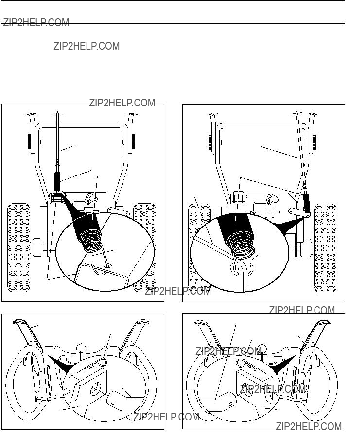
INSTALL TRACTION DRIVE CONTROL ROD
(See Figs. 3 and 4)
The traction drive control rod has the long loop on the end of the spring as shown.
1.Slide rubber sleeve up rod and hook end of spring into pivot bracket with loop opening down as shown.
2.With top end of rod positioned under left side of control panel, push rod down and insert top end of rod into hole in drive control bracket. Secure with retainer spring.
FIG. 3
TRACTION
DRIVE
CONTROL
ROD
DRIVE
CONTROL
BRACKET
FIG. 4
INSTALL AUGER CONTROL ROD (See Figs. 5 and 6)
The auger control rod has the short loop on the end of the spring as shown.
1.Slide rubber sleeve up rod and hook end of spring into control arm with loop opening up as shown.
2.With top end of rod positioned under right side of control panel, push down on rod and insert end of rod into hole in auger control bracket. Secure with retainer spring.
FIG. 5
AUGER
CONTROL
BRACKET
FIG. 6
6

ASSEMBLY /
INSTALLDISCHARGE CHUTE / CHUTE ROTATER HEAD
(See Fig. 7)
NOTE: The
1.Place discharge chute assembly on top of chute base with discharge opening toward front of snow thrower.
2.Position chute rotater head over chute bracket. If neces- sary,rotatechuteassemblytoalignsquareandpinonun- derside of chute rotater head with holes in chute bracket.
3.With chute rotater head and chute bracket aligned, position chute rotater head on pin and threaded stud of mounting bracket.
4.Install 3/8 washer and locknut on threaded stud and tighten securely.
FIG. 7
INSTALL CHUTE DEFLECTOR REMOTE CONTROL
(See Figs. 8 and 9)
1.Install remote cable bracket to discharge chute with
2.Install remote cable eyelet to chute de???ector with
3.Install spring hooks between hex nuts on chute rotater head and into hole in chute de???ector as shown.
FIG. 8
FIG. 9
CHECK TIRE PRESSURE
The tires on your snow thrower were overin???ated at the fac- tory for shipping purposes. Correct and equal tire pressure is important for best snow throwing performance.
???Reduce tire pressure to
7

OPERATION
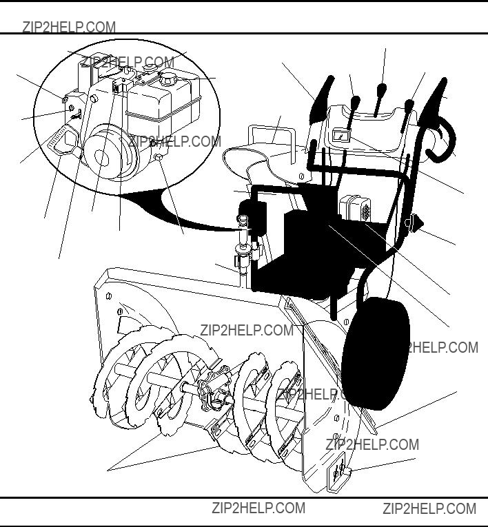
KNOW YOUR SNOW THROWER
READ THIS OWNER'S MANUAL AND ALL SAFETY RULES BEFORE OPERATING YOUR SNOW THROWER. Compare the illustrations with your snow thrower to familiarize yourself with the location of various controls and adjustments. Save this manual for future reference.
These symbols may appear on your snow thrower or in literature supplied with the product. Learn and understand their meaning.
OR WARNING
READ AND FOLLOW ALL SAFETY INFORMATION
AND INSTRUCTIONS BEFORE USE OF THIS PRODUCT.
FORWARD REVERSE KEEP THESE INSTRUCTIONS FOR FUTURE REFERENCE.
OPERATION
SPARK
PLUG
SAFETY
IGNITION
KEY
CHOKE
CON-
TROL
NOTE: ITEMS ABOVE
ARE SHOWN IN
THEIR TYPICAL
LOCATION ON THE
ENGINE. ACTUAL
LOCATION MAY VARY
WITH THE ENGINE
ON YOUR UNIT.
AUGERS
ELECTRIC
START
BUTTON
OIL DRAIN PLUG
HANDLE
KNOB
MUFFLER
TOOLBOX
DRIFT
CUTTER
SKID PLATE
FIG. 10
MEETS A.N.S.I. SAFETY REQUIREMENTS
Our snow throwers conform to the standards of the American National Standards Institute.
Toolbox - used to store spare shear bolts, locknuts and wrench.
Safety ignition key - must be inserted for the engine to start and run. Remove when snow thrower is not in use.
Electric start button - used for starting the engine.
Recoil (auxiliary) starter handle - used for starting engine.
Primer - pumps additional fuel from the carburetor to the cylinder for use when starting a cold engine.
Choke Control - used for starting a cold engine.
Throttle/engine control - used to select either FAST or SLOW engine speed and to STOP the engine.
LH and RH turn triggers - used to steer the snow thrower.
Drive speed control lever - used to select forward or reverse motion and speed of snow thrower.
Traction drive control lever - used to engage
Auger control lever - used to engage auger motion (throw snow).
Discharge chute control lever - used to change the di- rection the snow is thrown.
De???ector remote control lever - used to change the distance the snow is thrown.
Skid plate - used to adjust height of scraper bar from the ground.
9 Drift cutter - used to cut through deep snowdrifts.

OPERATION
The operation of any snow thrower can result in foreign objects thrown into the eyes, which can result in severe eye damage. Always wear


 safety glasses or eye shields while operating your snow thrower or performing any adjust- ments or repairs. We recommend standard safety glasses
or a wide vision safety mask worn over spectacles.
TO USE CHOKE CONTROL (See Fig. 13)
The choke control is located on the engine. Use the choke control whenever you are starting a cold engine. Do not use to start a warm engine.
???To engage choke, turn knob clockwise. Slowly turn knob counterclockwise to disengage.
AUGER
??? Release the auger control lever to stop throwing snow.
ENGINE
1.Move throttle control to ???STOP??? position.
2.Remove (do not turn) safety ignition key to prevent unauthorized use.
NOTE: Never use choke to stop engine.
TO USE FUEL
The fuel
OFF
OPEN
TO CONTROL SNOW DISCHARGE (See Fig. 14)
WARNING: Snow throwers have ex- posed rotating parts, which can cause severe injury from contact, or from ma- terial thrown from the discharge chute. Keep the area of operation clear of all persons, small children and pets at all times including startup.
WARNING: If the discharge chute or au- ger become clogged,
The DIRECTION in which snow is to be thrown is controlled by the discharge chute control lever.
???To change the discharge chute position, press down- ward on discharge chute control lever and move lever left or right until chute is in desired position. Be sure lever springs back and locks into desired position.
The DISTANCE that snow is thrown is controlled by the position of the chute de???ector. Set the de???ector low to throw snow a short distance; set the de???ector higher to throw snow farther.
SLOW
CHUTE DEFLECTOR
REMOTE CONTROL LEVER
OPERATION
TO THROW SNOW (See Fig. 15)
The auger rotation is controlled by the auger control lever located on the right side handle.
???Squeeze auger control lever to handle to engage the auger and throw snow.
???Release the auger control lever to stop throwing snow.
AUGER
CONTROL
LEVER
FIG. 15
USING THE
In certain snow conditions, the discharge chute may be- come clogged with ice and snow. Use the
When cleaning, repairing, or inspecting, make certain all controls are disengaged and the auger/impeller and all moving parts have stopped. Disconnect the spark plug wire and keep the wire away from the spark plug to pre- vent accidental starting.
???Release the auger control lever and shut off the engine.
???Remove the
After the packed snow has been dislodged, return the clean- out tool to it's mounting clip by pushing it into the clip.
???Make sure the discharge chute is pointed in a safe direc- tion (no vehicles, buildings, people, or other objects are in the direction of discharge) before restarting engine.
???Restart the engine, then squeeze the auger control lever to the handle to clear snow from the auger hous- ing and the discharge chute.
TO MOVE FORWARD AND BACKWARD (See Fig. 17)
???Squeeze traction drive control lever to handle to engage the drive system.
???Release traction drive control lever to stop the forward or reverse movement of the snow thrower.
SPEED and DIRECTION are controlled by the drive speed control lever.
???Press downward on the speed control lever and move lever to desired position BEFORE engaging the trac- tion drive control lever. Be sure lever springs back and locks into desired position.
CAUTION: Do not move speed control lever when traction drive control lever is engaged. Damage to the snow thrower can result.
???Slower speeds are for heavier snow and faster speeds are for light snow and transporting the snow thrower. It is recommended that you use a slower speed until you are familiar with the operation of the snow thrower.
NOTE: When both traction drive and auger control levers are engaged, the traction drive control lever will lock the auger control lever in the engaged position. This will allow you to release your right hand from the handle and adjust the discharge chute direction without interrupting the snow throwing process.
TRACTION DRIVE
CONTROL LEVER
DRIVE SPEED
CONTROL LEVER
FIG. 17
POWER STEERING OPERATION (See Fig. 18)
Steering triggers are used to assist in steering your snow thrower. The triggers are located on the underside of each handle. When a trigger is squeezed, it disengages the drive wheel on that side of snow thrower and allows it to turn in that direction.
???To turn left ??? squeeze left side trigger.
???To turn right ??? squeeze right side trigger.

OPERATION
TO ADJUST SKID PLATES (See Fig. 19)
NOTE: The wrench provided in your parts bag may be used to adjust the skid plates.
Skid plates are located on each side of the auger housing and adjust the clearance between the scraper bar and the ground surface. Adjust skid plates evenly to proper height for current surface conditions. For removal of snow in normal conditions, such as a paved driveway or sidewalk, place skid plates in the highest position (lowest scraper clearance) to give a 1/8" clearance between the scraper bar and the ground. Use a middle position if the surface to be cleared is uneven.
NOTE: It is not recommended to operate the snow thrower over gravel or rocky surfaces. Objects such as gravel, rocks or other debris, can easily be picked up and thrown by the impeller, which can cause serious personal injury, property damage or damage to the snow thrower.
???If snow thrower must be operated over gravel surface, use extra caution and be sure skid plates are adjusted to lowest (highest scraper clearance) position.
1.Shut off engine and wait for all moving parts to stop.
2.Adjust skid plates by loosening the rear 1/2" hex nut only, then moving skid plate to desired position. Be sure both plates are adjusted evenly. Tighten securely.
HIGH POSITION
(LOW GROUND
CLEARANCE)
AUGER
HOUSING
SKID PLATE
1/2" HEX NUT
LOW POSITION (HIGH GROUND CLEARANCE)
FIG. 19
SCRAPER BAR
The scraper bar is not adjustable, but is reversible. After considerable use it may become worn. When it has worn almost to the edge of the housing, it can be reversed, providing additional service before requiring replacement. Replace a damaged or worn scraper bar.
TO USE DRIFT CUTTERS (See Fig. 20)
Use the drift cutters to cut through deep snowdrifts that are higher than the front of the snow thrower.
???Loosen upper adjustment nut enough to allow drift cutter to be raised to highest position and tighten nut securely. Repeat for opposite side of snow thrower.
AUGER
HOUSING
ADJUST-
MENT NUT
???When not using drift cutters, loosen adjustment nut, lower to storage position and tighten nut securely.
BEFORE STARTING THE ENGINE
CHECK ENGINE OIL LEVEL (See Fig. 21)
The engine on your snow thrower has been shipped, from the factory, already ???lled with oil.
1.Check engine oil with snow thrower on level ground.
2.Remove oil ???ll cap/dipstick and wipe clean, reinsert the dipstick and screw tight, wait for a few seconds, remove and read oil level. If necessary, add oil until ???FULL??? mark on dipstick is reached. Do not over???ll.
???To change engine oil, see ???TO CHANGE ENGINE OIL??? in the Maintenance section of this manual.
ADD GASOLINE (See Fig. 21)
???Fill fuel tank to bottom of tank ???ller neck. Do not over- ???ll. Use fresh, clean, regular unleaded gasoline with a minimum of 87 octane. Do not mix oil with gasoline. Purchase fuel in quantities that can be used within 30 days to assure fuel freshness.
WARNING: Wipe off any spilled oil or fuel. Do not store, spill or use gasoline near an open ???ame.
CAUTION: Alcohol blended fuels (called gas- ohol or using ethanol or methanol) can attract moisture which leads to separation and for- mation of acids during storage. Acidic gas can damage the fuel system of an engine while in storage. To avoid engine problems, the fuel system should be emptied before storage of 30 days or longer. Drain the gas tank, start the engine and let it run until the fuel lines and carburetor are empty. Use fresh fuel next season. See Storage Instructions for additional information. Never use engine or carburetor cleaner products in the fuel tank or permanent damage may occur.

OPERATION
TO START ENGINE
???Be sure fuel
Your snow thrower engine is equipped with both a 120 Volt A.C. electric starter and a recoil starter. The electric starter is equipped with a
???Be sure your house is a 120 Volt A.C.
WARNING: Do not use the electric starter if your house is not a 120 Volt A.C.
COLD START - ELECTRIC STARTER
1.Insert safety ignition key (packed separately in parts bag) into ignition slot until it clicks. DO NOT turn the key. Keep the extra safety ignition key in a safe place.
2.Place throttle control in FAST position.
3.Rotate choke control to FULL position.
4.Connect the power cord to the engine.
5.Plug the other end of the power cord into a
6.Push the primer three (3) times.
7.Push starter button until engine starts.
IMPORTANT: Do not crank engine more than ???ve con- tinuous seconds between each time you try to start. Wait 5 to 10 seconds between each attempt.
8.When the engine starts, release the starter button and slowly move the choke control to the ???OFF??? position.
9.Disconnect the power cord from the receptacle ???rst, then from the engine.
Allow the engine to warm up for a few minutes. Engine will not develop full power until it has reached normal operat- ing temperature.
WARM START - ELECTRIC STARTER
Follow the steps above, keeping the choke control in the OFF position.
COLD START - RECOIL STARTER
1.Insert safety ignition key into the ignition slot until it clicks. DO NOT turn the key. Keep the extra safety ignition key in a safe place.
2.Place throttle control in FAST position.
3.Rotate choke control to FULL position.
4.Push the primer four (4) times if the temperature is below 15??F, or two (2) times if temperature is between 15?? and 50??F. If temperature is above 50??F, priming is not necessary.
NOTE: Over priming may cause ???ooding, preventing the engine from starting. If you do ???ood the engine, wait a few minutes before attempting to start and DO NOT push the primer.
5.Pull recoil starter handle quickly. Do not allow starter rope to snap back.
6.When the engine starts, release the recoil starter handle and slowly move the choke control to the OFF position.
Allow the engine to warm up for a few minutes. Engine will not develop full power until it has reached normal operating temperature.
WARM START - RECOIL STARTER
Follow the steps above, keeping the choke in the OFF position. DO NOT push the primer.
BEFORE STOPPING
Run the engine for a few minutes to help dry off any mois- ture on the engine.
To avoid possible
ELECTRIC STARTER
1.Connect the power cord to the engine.
2.Plug the other end of the power cord into a
3.While the engine is running, push starter button and spin the starter for several seconds.
NOTE: The unusual sound made while starter is spinning will not harm the engine or starter.
4.Disconnect the power cord from the receptacle ???rst, then from the engine.
RECOIL STARTER
1.While the engine is running, pull the recoil starter handle with rapid, full arm strokes three or four times.
NOTE: The unusual sound made while pulling the recoil starter handle will not harm the engine or starter.
IF RECOIL STARTER HAS FROZEN
If the recoil starter has frozen and will not turn the engine, proceed as follows:
1.Grasp the recoil starter handle and slowly pull as much rope out of the starter as possible.
2.Release the recoil starter handle and let it snap back against the starter.
If the engine still fails to start, repeat the above steps or use the electric starter.
SNOW THROWING TIPS
???Always operate the snow thrower with the engine at full throttle. Full throttle offers the best performance.
???Go slower in deep, freezing or heavy wet snow. Use the drive speed control, NOT the throttle, to adjust speed.
???It is easier and more ef???cient to remove snow imme- diately after it falls.
???The best time to remove snow is the early morning. At this time the snow is usually dry and has not been ex- posed to the direct sun and warming temperatures.
???Slightly overlap each successive path to ensure all snow will be removed.
???Throw snow downwind whenever possible.
???Adjust the skid plates to proper height for current snow conditions. See ???TO ADJUST SKID PLATES??? in this section of this manual.
13

???For extremely heavy snow, reduce the width of snow removal by overlapping previous path and moving slowly.
???Keep engine clean and clear of snow during use. This will help air ???ow and extend engine life.
???After
???Clean the entire snow thrower thoroughly after each use and wipe dry so it is ready for next use.
WARNING: Do not operate snow thrower ifweather conditionsimpair vis- ibility. Throwing snow during a heavy, windy snowstorm can blind you and be hazardous to the safe operation of the snow thrower.
The warranty on this snow thrower does not cover items that have been subjected to operator abuse or negligence. To receive full value from the warranty, operator must maintain snow thrower as instructed in this manual. Some adjust- ments will need to be made periodically to properly maintain your snow thrower.
All adjustments in the Service and Adjustments section of this manual should be checked at least once each season.
???Once a year, you should replace the spark plug and check belts for wear. A new spark plug will help your engine run better and last longer.
???Follow the maintenance schedule in this manual.
NOTE: Use only Original Equipment Manufacturer (OEM) parts to service this unit. Failure to do so can cause the unit to malfunction and pose a risk of injury to the operator.
BEFORE EACH USE
1.Check engine oil level.
2.Check for loose fasteners.
3.Check controls to be sure they are functioning properly.
??? SAE
??? See ???ENGINE??? in
Maintenance section
???General Purpose Grease
??? Pivot points

MAINTENANCE
SNOW THROWER
Always observe safety rules when performing maintenance.
TIRES
???Maintain proper air pressure in both tires
???Keep tires free of gasoline / oil, which can harm rubber.
NOTE:To seal tirepunctures and prevent???at tires dueto slow leaks, tire sealant may be purchased from your local parts dealer. Tire sealant also prevents tire dry rot and corrosion.
Check
The
AUGER GEAR CASE
???The gear case was ???lled with lubricant to the proper level at the factory. The only time the lubricant needs atten- tion is if service has been performed on the gear case.
???If lubricant is required, use only Ronex ED #1 grease.
TRACTION DRIVE SYSTEM
DO NOT lubricate the drive components inside the snow thrower. The sprockets, hex shafts, drive disc and friction wheel require no lubrication. The bearings and bushings are lifetime lubricated and require no maintenance.
CAUTION:Any lubricating of the above compo- nents can cause contamination of the friction wheel and damage to the drive system of your snow thrower.
ENGINE
See engine manual.
LUBRICATION
Use only high quality detergent oil rated with API service classi???cation
Check the crankcase oil level before starting the engine and after each ???ve (5) hours of continuous use. Tighten oil ???ll cap / dipstick securely each time you check the oil level.
TO CHANGE ENGINE OIL
Determine temperature range anticipated before next oil change. All oil must meet API service classi???cation
???Be sure snow thrower is on level surface.
???Oil will drain more freely when warm.
???Catch oil in a suitable container.
NOTE: The left side wheel may be removed from snow thrower for easier access to the oil drain plug and place- ment of a suitable container. The unit tilted, resting on the frame with the left wheel removed, will help drain any oil trapped inside the engine. (See ???TO REMOVE WHEELS??? in the Service and Adjustments section of this manual).
1.Disconnect spark plug wire from spark plug and place wire where it cannot come in contact with plug.
2.Clean area around drain plug.
3.Remove drain plug and drain oil in a suitable container.
4.Install drain plug and tighten securely.
5.Wipe off any spilled oil from snow thrower and engine.
6.Install left wheel (if removed for draining oil). Be sure to install klick pin into proper hole in wheel axle (See ???TO REMOVE WHEELS??? in the Service and Adjustments section of this manual).
7.Remove oil ???ll cap/dipstick. Be careful not to allow dirt to enter the engine.
8.Re???ll engine with oil through oil dipstick tube. Pour slowly. Do not over???ll. For approximate capacity see ???PRODUCT SPECIFICATIONS??? section of this manual.
9.Use gauge on oil ???ll cap/dipstick for checking level. Be sure dipstick cap is tightened securely for accurate reading. Keep oil at ???FULL??? line on dipstick.
10.Wipe off any spilled oil.
MUFFLER
Inspect and replace corroded muf???er as it could create a ???re hazard and/or damage.
SPARK PLUG
Replace spark plug at the beginning of each season or after every 100 hours of operation, whichever occurs ???rst. Spark plug type and gap setting are shown in the ???PRODUCT SPECIFICATIONS??? section of this manual.

SERVICE AND ADJUSTMENTS
WARNING: To avoid serious injury, before performing any service or ad- justments:
1.Be sure throttle is in STOP position.
2.Remove safety ignition key.
3.Make sure the augers and all moving parts have completely stopped.
4.Disconnect spark plug wire from spark plug and place wire where it cannot come in contact with plug.
1.Disengage all controls and move throttle control to STOP position. Wait for all moving parts to stop.
2.Disconnect spark plug wire from spark plug and place wire where it cannot come in contact with plug.
3.Align holes in impeller hub with holes in impeller shaft and install two (2) new
CAUTION: Do not substitute. Use only original equipment capscrew/shear bolts as supplied with your snow thrower.
4.Connect spark plug wire to spark plug.

SERVICE AND ADJUSTMENTS
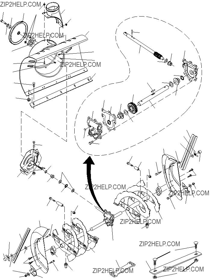
TO REPLACE BELTS (See Fig. 24)
The auger and traction drive belts are not adjustable. If the belts are damaged or begin to slip from wear, they should be replaced. It is recommended that the belt(s) be replaced by a quali???ed service center.
NOTE: It is recommended that both the auger and traction drive belt be replaced at the same time.
The
WARNING: Belt replacement requires separation of the snow thrower. While separating the auger housing from the frame assembly, it is important that an assistant stand in the operating position and hold the snow thrower handles. Se- rious personal injury and/or damage to the unit could occur if the snow thrower should fall during the belt changing process.
HANDLES
1.REMOVE GASOLINE FROM FUEL TANK - Drain gaso- line from fuel tank into a suitable container, outdoors, away from ???re or ???ame. Wipe up any spilled gasoline.
2.REMOVE DISCHARGE CHUTE - Loosen locknut securing chute rotator head to mounting bracket only enough to allow chute rotator head to be raised and discharge chute to be removed from snow thrower.
3.REMOVE BELT COVER - See ???TO REMOVE BELT COVER??? in this section of this manual.
4.REMOVE ENGINE PULLEY - Remove bolt, lockwasher and ???at washer securing pulley to engine crankshaft. Remove outside (auger) pulley only from crankshaft.
5.SEPARATE SNOW THROWER - With your assistant standing in the operating position holding the handles, remove the two (2) bolts and lock washers holding auger housing and frame together.
WARNING: As the last bolt is removed, have your assistant carefully lower the handles down to the ground.
6.REMOVE AUGER BELT from around pulley.
7.RELIEVE TENSION ON TRACTION DRIVE BELT IDLER and remove traction drive belt from around pulleys.
HINT: Insert a 3/8" drive ratchet (in the ???ON??? position) into the square hole in idler arm and rotate ratchet clockwise to relieve tension.
8.With tension relieved on idler, install new traction drive belt around pulleys and inside belt keepers.
9.Place auger belt around and inside the groove of auger pulley only.
10.While your assistant slowly raises handles to rejoin the auger housing and frame assembly, pull up on the auger belt and squeeze sides together above pulley so belt is fully seated in groove of pulley.
11.Bring snow thrower completely together and check carefully for proper routing of belts. If auger belt has become dislodged from the pulley (by catching the idler arm bracket while bringing snow thrower together), separate the snow thrower and repeat step 10. Belt must be fully seated in pulley groove when bringing the snow thrower together.
12.Install the two (2) hex bolts and lock washers and tighten securely.
13.INSTALL ENGINE PULLEY - Place belt in pulley groove and slide pulley on crankshaft. Install ???at washer, lock- washer and bolt and tighten securely
14.INSTALL BELT COVER and two (2) screws. Tighten securely.
15.INSTALL DISCHARGE CHUTE ??? See ???INSTALL DIS- CHARGE CHUTE / CHUTE ROTATER HEAD??? in the Assembly /
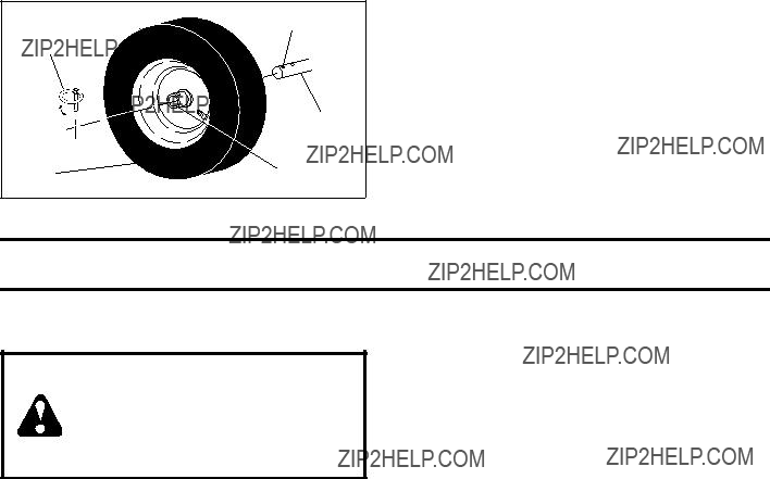
TO REMOVE WHEELS (See Fig. 25)
???Remove the klik pin and remove wheel from axle.
IMPORTANT: When installing wheel, be sure to use the axle hole closest to the end of the shaft ??? do not use the hole in the wheel hub (if equipped). Inner hole in axle and hole in wheel hub are not used for your model snow thrower.
AXLE
FIG. 25
NOTE: To seal punctures or prevent ???at tires due to slow leaks, tire sealant may be purchased from your local parts dealer. Tire sealant also prevents tire dry rot and corrosion.
ENGINE
See engine manual.
CARBURETOR
Your carburetor is not adjustable. Engine performance should not be affected at altitudes up to 7,000 feet (2,134 meters). If your engine does not operate properly due to suspected carburetor problems, take your snow thrower to a quali???ed service center.
ENGINE SPEED
Never tamper with the engine governor, which is factory set for proper engine speed. Overspeeding the engine above the factory high speed setting can be dangerous and will void the warranty. If you think the
STORAGE
Immediately prepare your snow thrower for storage at the end of the season or if the unit will not be used for 30 days or more.
WARNING: Never store the snow thrower with gasoline in the tank inside a building where fumes may reach an open ???ame, spark or pilot light as on a furnace, water heater, clothes dryer or gas appliance. Allow the engine to cool before storing in any enclosure.
SNOW THROWER
When snow thrower is to be stored for a period of time, clean it thoroughly, remove all dirt, grease, leaves, etc. Store in a clean, dry area.
1.Clean entire snow thrower (See ???CLEANING??? in the Maintenance section of this manual).
2.Inspect and replace belts, if necessary (See ???TO RE- PLACE BELTS??? in the Service andAdjustments section of this manual).
3.Lubricate as shown in the Maintenance section of this manual.
4.Be sure that all nuts, bolts, screws, and pins are securely fastened. Inspect moving parts for damage, breakage and wear. Replace if necessary.
5.Touch up all rusted or chipped paint surfaces; sand lightly before painting.
ENGINE
See engine manual.
???Empty the fuel tank by starting the engine and letting it run until the fuel lines and carburetor are empty.
???Never use engine or carburetor cleaner products in the fuel tank or permanent damage may occur.
???Use fresh fuel next season.
NOTE: Fuel stabilizer is an acceptable alternative in min- imizing the formation of fuel gum deposits during storage. Add stabilizer to gasoline in fuel tank or storage container. Always follow the mix ratio found on stabilizer container. Run engine at least 10 minutes after adding stabilizer to allow the stabilizer to reach the carburetor. Do not drain the gas tank and carburetor if using fuel stabilizer.
ENGINE OIL
Drain oil (with engine warm) and replace with clean en- gine oil. (See ???ENGINE??? in the Maintenance section of this manual).
CYLINDER
1.Remove spark plug.
2.Pour one ounce (29 ml) of oil through spark plug hole into cylinder.
3.Pull recoil starter handle slowly a few times to distribute oil.
4.Replace with new spark plug.
OTHER
???Do not store gasoline from one season to another.
???Replace your gasoline can if your can starts to rust. Rust and/or dirt in your gasoline will cause problems.
???If possible, store your snow thrower indoors and cover it to protect it from dust and dirt.
???Cover your snow thrower with a suitable protective cover that does not retain moisture. Do not use plastic. Plastic cannot breathe, which allows condensation to form and will cause your snow thrower to rust.
IMPORTANT: Never cover snow thrower while engine/ exhaust area is still warm.

TROUBLESHOOTING
See appropriate section in manual unless directed to a quali???ed service center.
19
SNOW THROWER - MODELNO.
16 4
15
14
5
7
9
8
6
48 19
54
18
SNOW THROWER - MODELNO.
NOTE: All component dimensions given in U.S. inches. 1 inch = 25.4 mm IMPORTANT: Use only Original Equipment Manufacturer (O.E.M.) replacement parts. Failure to do so could be hazardous, damage your snow thrower and void your warranty. 21

SNOW THROWER - MODELNO.
22 

2
6
26
 22
22
27
28
25
3
20
29
23
4
5
6 9
23
27
7
30
31
16
18
17 
8
 10
10
11
 12
12
14
3
13
15
8
22
SNOW THROWER - MODELNO.
6532 40
7532 40
8 532 15
9532 18
10532 17
11532 17
12532 19
13872 25
14532 75
15532 40
16532 18
17532 17
18532 12
19532 18
20 532 19
22874 04
23532 19
25532 19
26532 19
27532 16
28532 18
29532 18
30532 19
31532 19
NOTE: All component dimensions given in U.S. inches. 1 inch = 25.4 mm IMPORTANT: Use only Original Equipment Manufacturer (O.E.M.) replacement parts. Failure to do so could be hazardous, damage your snow thrower and void your warranty. 23

SNOW THROWER - MODELNO.
1
5
31
32
 10 15
10 15
12
14
16
17
31
32
2
28
5
36
45 9
42 37
35
18
22
24
26
5
4
4
12
15
13
15 11 19
17
16
22
21
23
20
24
25
27
27
30
38 39
SNOW THROWER - MODELNO.
1532 40
2532 40
4532 17
5532 16
6817 06
7532 17
8532 19
9532 19
10532 19
13532 18
14532 18
15532 75
16819 13
17532 17
18532 18
19532 19
20532 18
21873 35
22 872 12
23532 18
24532 18
25532 18
26532 17
33532 19
34532 18
35532 06
36532 17
37532 19
38532 18
- - 532 18
39532 17
40532 17
42532 19
43532 19
44532 19
45532 70
46532 17
NOTE: All component dimensions given in U.S. inches. 1 inch = 25.4 mm IMPORTANT: Use only Original Equipment Manufacturer (O.E.M.) replacement parts. Failure to do so could be hazardous, damage your snow thrower and void your warranty. 25

SNOW THROWER - MODELNO.
5
4
1
5
2
1 4
14
12
16
21
20
18
18
44
19
26
28
31
30
22
26
21
4
 27 5
27 5
2
 24
24
41
7
4
15
23
6
2 

5 4
25
 43
43
41 33
36
38  39
39  40
40
35 33  37
37
SNOW THROWER - MODELNO.
9532 18
10532 18
11532 18
12532 18
13532 17
14532 18
15532 17
16532 18
17532 17
18532 19
19873 93
20532 17
21 874 76
22532 08
23532 18
24532 18
25532 17
26532 19
27 532 40
28532 19
29532 18
30532 18
33532 18
34532 18
35532 18
36532 19
37532 19
43532 17
44532 18
NOTE: All component dimensions given in U.S. inches. 1 inch = 25.4 mm IMPORTANT: Use only Original Equipment Manufacturer (O.E.M.) replacement parts. Failure to do so could be hazardous, damage your snow thrower and void your warranty. 27

SNOW THROWER - MODELNO.
NOTE: All component dimensions given in U.S. inches. 1 inch = 25.4 mm IMPORTANT: Use only Original Equipment Manufacturer (O.E.M.) replacement parts. Failure to do so could be hazardous, damage your snow thrower and void your warranty. 29

1 13 2
8
 6
6
NOTE: All component dimensions given in U.S. inches. 1 inch = 25.4 mm IMPORTANT: Use only Original Equipment Manufacturer (O.E.M.) replacement parts. Failure to do so could be hazardous, damage your snow thrower and void your warranty. 31

RANTYWAR TEMENTSTA