Operator??s manual
Rider 16
Please read these instructions carefully and make sure you understand them before using the machine.
English
Operator??s manual
Rider 16
Please read these instructions carefully and make sure you understand them before using the machine.
English

Svenska ??? 31

CONTENTS
Operator???s Manual for Rider 16
IMPORTANT INFORMATION
Read carefully through the Operator???s manual so that you know how to use and maintain the Rider before you use it.
For service measures other than those described in this manual, please contact an authorised dealer that provides parts and service.
English ??? 1

INSTRUCTION
Dear customer
Thank you for choosing a Husqvarna Rider. Husqvarna Riders are built to a unique design with a front- mounted cutting unit and a patented
We hope you will find this operator???s manual very useful. By following its instructions (on operation, service, maintenance, etc.) you will significantly extend the life of the machine and even its
When you sell your Rider, make sure you pass on the operator???s manual to the new owner.
Travel and transport on public roads
Check the relevant road traffic regulations before driving the machine on a public road. If transporting the machine on another vehicle always use approved securing devices and make sure that the machine is securely held.
Towing
When your machine is equipped with a hydrostatic transmission you should, if necessary, only tow the machine over short distances and at a low speed, otherwise there is a risk of damaging the transmission.
Intended use
This machine is designed solely for cutting grass on conventional lawns and other cleared and leveled ground without obstacles, as rocks, stumps etc., and, in conjunction with accessories supplied by the manufacturer even for other special tasks for which instructions are delivered with the accessory. Use in any other way is considered as contrary to the intended use. Compliance with and strict adherence to the conditions of operation, service and repair as specified by the manufacturer also constitute essential elements of the intended use.
This machine should be operated, serviced and repaired only by persons who are familiar with its particular characteristics and who are acquainted with the relevant safety procedures.
Accident prevention regulations, all other generally recognised regulations on safety and occupational medicine, and all road traffic regulations must be observed at all times.
Any arbitrary modifications carried out to this machine may relieve the manufacturer of liability for any resulting damage or injury
2 ??? English

SAFETY INSTRUCTIONS
Good service
Husqvarna products are sold all over the world and only through servicing dealers. This is to ensure that you, the customer, get the best support and service. Before the machine is delivered it undergoes inspection and is adjusted by your dealer.
When you need spare parts or advice on service issues, warranty terms, etc., contact:
Serial number
The serial number can be found on the printed plate attached to the front,
???The machines type designation.
???The manufacturer???s type number.
???The machine???s serial number.
State the type designation and serial number when ordering spare parts.
The engine number is punched on a plate that is riveted to the fan cover. The plate states:
???Model.
???Type.
???Code.
Please state these when ordering spare parts.
The transmission???s serial number is stated on the barcode decal located on the front of the housing on the
???Type designation is stated above the barcode and starts with the letter ???K???.
???The serial number is stated above the barcode and has the prefix ???s/n???.
???The manufacturer???s type number is stated under the barcode and has the prefix ???p/n???. State the type designation and serial number when ordering spare parts.
English ??? 3

EXPLANATION OF SYMBOLS
These symbols are on the machine and in the operator???s manual.
Study them carefully so that you know what they mean.
Read the operator???s manual
R N
Reverse NeutralFastSlow Engine offBatteryChokeFuel
Starting instructions Read the instructions Check the engine???s oil level
Check the hydrostat???s oil level Lift up the cutting unit
Put the hydrostat pedals in the neutral position
Brake
If the engine is cold use the choke Start the engine
Release the parking brake before driving
Speed limiter pedal forwards
Neutral
Speed limiter pedal reverse
Switch off the engine and take off the ignition cable before repairs or maintenance
4 ??? English

SAFETY INSTRUCTIONS
Safety instructions
These instructions are for your safety. Read them carefully.
WARNING!
The inserted symbol means that important safety instructions need to be observed. It applies to your safety.
General use
???Read all the instructions in this operator???s manual and on the machine before you start it. Ensure you understand them and then observe them.
???Learn how to use the machine and its controls safely and learn to how to stop quickly. Also learn to recognize the safety decals.
???Only allow the machine to be used by adults who are familiar with its use.
???Make sure nobody else is in the vicinity of the machine when you start the engine, engage the drive or drive off.
???Make sure animals and people maintain a safe distance from the machine.
???Stop the machine if any one enters the working area.
???Clear the area of objects such as stones, toys, wires, etc. that may become caught in the blades and be thrown out.
???Look out for the ejector and do not direct it towards anyone.
???Stop the engine and prevent the engine from being started until you have cleaned the outlet channel.
Read the operator???s manual before starting the machine.
???Remember the operator is responsible for danger or accidents.
???Never carry passengers. The machine is only intended to be used by one person.
???Always look downwards and backwards before and while reversing. Keep watch for both large and small obstacles.
???Slow before cornering.
???Switch off the blades when you are not mowing.
Clear the area of objects before mowing.
Never carry passengers.
WARNING!
This machine can sever hands and feet as well as throw objects. Failure to observe the safety instructions can result in serious injuries.
English ??? 5
SAFETY INSTRUCTIONS
???Take care when rounding a fixed object, so that the blades do not hit it. Never run the machine over foreign objects.
???Only use the machine in daylight or in other
???Never use the machine if you are tired, if you have consumed alcohol, or if you are taking other drugs or medication that can affect your vision, judgment or
???Keep an eye on the traffic when working close to a road or when crossing it.
???Never leave the machine unsupervised with the engine running. Always stop the blades, apply the parking brake, stop the engine and remove the keys before leaving the machine.
???Never allow children or other persons not trained in the use of the machine to use or service it. Local laws may regulate the age of the user.
WARNING!
Engine exhaust, some of its constituents and certain vehicle components contain or emit chemicals considered to cause cancer, birth defects or other reproductive impairment. The engine emits carbon monoxide, which is a colourless, poisonous gas. Do not use the machine in enclosed spaces.
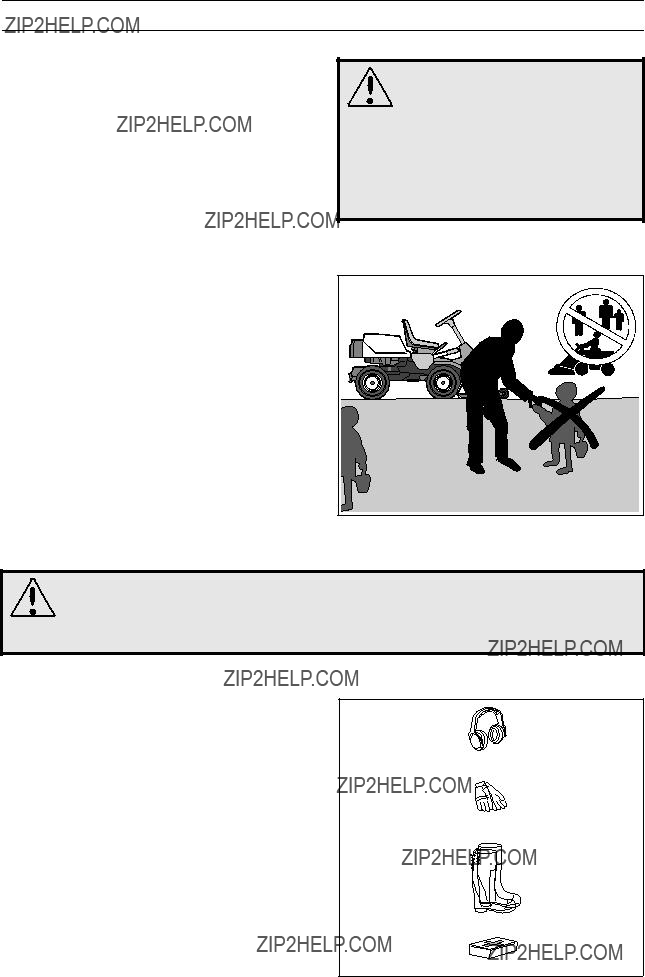
Keep children away from the area to be mowed.
WARNING!
You must use approved personal protective equipment whenever you use the ma- chine. Personal protective equipment cannot eliminate the risk of injury but it will reduce the degree of injury if an accident does happen. Ask your dealer for help in choosing the right equipment.
???Make sure that you have first aid equipment
close at hand when using the machine.
???Never use the machine when barefoot. Always wear protective shoes or protective boots,
preferably with steel toes.
??? Wear approved protective glasses or
??? Never wear loose fitting clothes that can catch in moving parts.
Personal protective equipment.
6 ??? English
SAFETY INSTRUCTIONS
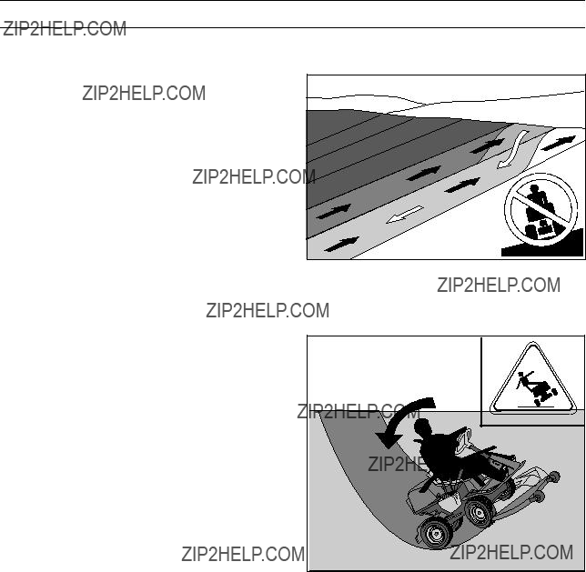
Driving on slopes
Driving on slopes is one of the operations where the risk of the driver losing control of the machine or of it overturning is the greatest; this can result in serious injury or death. All slopes demand extra care. If you cannot reverse up a slope or if you feel unsure, do not mow it.
Proceed as follows:
???Remove obstacles such as stones, branches, etc.
???Mow upwards and downwards, not sideways.
???Do not use the machine on ground that slopes more than 15??.
???Avoid starting or stopping on a slope. If the tyres start to slip, stop the blades and drive slowly down the slope.
???Always drive smoothly and slowly on slopes.
???Do not make any sudden changes in speed or direction.
???Avoid unnecessary turns on slopes, if necessary, turn slowly and gradually downwards if possible.
???Watch out for and avoid driving over furrows, holes and bumps. It is easier for the machine to overturn on uneven ground. Tall grass can hide obstacles.
???Drive slowly. Do not turn the wheel sharply. The machine
???Take extra care if any attachments are fitted that can change the stability of the machine.
???Do not mow too close to edges, ditches or banks. The machine can suddenly overturn if one wheel comes over the edge of a steep slope or a ditch, or if an edge gives way.
???Do not mow wet grass. It is slippery, and tyres can lose their grip so that the machine skids.
???Do not try to stabilize the machine by putting your foot on the ground.
???When cleaning the chassis the machine must never be driven close to an edge or ditch.
???Follow the manufacturer???s recommendations regarding wheel weights or counterbalance weights to increase stability.
Mow upwards and downwards on slopes, not sideways.
Be especially careful when driving on slopes.
English ??? 7

SAFETY INSTRUCTIONS
Children
???Serious accidents may occur if you fail to be on your guard for children in the vicinity of the machine. Children are often attracted to the machine and mowing. Never assume that children will remain where you last saw them.
???Keep children away from the area to be mowed and under close supervision by another adult.
???Keep an eye out and shut off the machine if children enter the work area.
???Before and during reversing procedures, look behind you and down for small children.
???Never allow children to ride along. They can fall off and seriously injure themselves or be in the way for safe manoeuvring of the machine.
???Never allow children to operate the machine.
???Be particularly careful near corners, bushes, trees or other objects that block your view.
Never allow children to operate the machine.
Maintenance
???Stop the engine. Prevent starting by removing the ignition cable from the spark plug or remove the ignition key before making any adjustments or carrying out maintenance.
???Never fill the fuel tank indoors.
???Petrol and petrol fumes are poisonous and extremely flammable. Be especially careful when handling petrol, as carelessness can result in personal injury or fire.
???Only store fuel in containers approved for the purpose.
???Never remove the fuel cap and fill the petrol tank while the engine is running.
???Allow the engine to cool before refuelling. Do not smoke. Do not fill petrol in the vicinity of sparks or naked flames.
Never fill the fuel tank indoors.
8 ??? English
SAFETY INSTRUCTIONS
???If leaks arise in the fuel system, the engine must not be started until the problem has been resolved.
???Store the machine and fuel in such a way that there is no risk that leaking fuel or fumes can cause any damage.
???Check the fuel level before each use and leave space for the fuel to expand, because the heat from the engine and the sun may otherwise cause the fuel to expand and overflow.
???Avoid overfilling. If you spill petrol on the machine, wipe up the spill and wait until it has evaporated before starting the engine. If you spill petrol on your clothing, change your clothing.
???Allow the machine to cool before performing any actions in the engine compartment.
???Be especially careful when handling battery acid. Acid on the skin can cause serious corrosive injuries. In the event of spillage on the skin wash immediately with water.
???Acid in the eyes can cause blindness, contact a doctor immediately.
???Take care with battery maintenance. Explosive gases form in the battery. Never perform maintenance on the battery while smoking or in the vicinity of open flames or sparks. This can cause the battery to explode and cause serious injuries.
???Make sure all nuts and bolts are tightened correctly and that the equipment is in good condition.
???Do not modify safety equipment. Check regularly to be sure it works properly. The machine must not be driven if protective plates, protective covers, safety switches or other protective devices are not fitted or are defective.
???Do not change the setting of governors and avoid running the engine at excessively high revs. If you run too fast, you risk damaging the machine components.
WARNING!
The engine and the exhaust system become very hot during operation.
Risk of burn injuries if touched.
WARNING!
The battery contains lead and lead pollutants, chemicals that are considered to cause cancer, birth defects or other repro- ductive impairment. Wash your hands after touching the battery.
Do not smoke when carrying out maintenance.
English ??? 9

SAFETY INSTRUCTIONS
???Never use the machine indoors or in spaces lacking proper ventilation. Exhaust fumes contain carbon monoxide, an odourless, poisonous and highly dangerous gas.
???Stop and inspect the equipment if you run over or into anything. If necessary, make repairs before starting.
???Never make adjustments with the engine running.
???The machine is tested and approved only with the equipment originally provided or recommended by the manufacturer.
???The blades are sharp and can cause cuts. Wrap the blades or wear protective gloves when handling them.
???Check regularly that the parking brake works. Adjust and maintain as required.
Never run the machine in an enclosed area.
???Check and observe local road traffic regulations before transporting or driving the machine on roads.
IMPORTANT INFORMATION
The parking brake is not sufficient to lock the machine during transport. Ensure you secure the machine firmly to the transporting vehicle. Reverse the machine on to the transporting vehicle to prevent it from overturning.
10 ??? English

PRESENTATION
Presentation
Congratulations on your choice of a top quality product which you will enjoy for many years.
These instructions describe the Rider 16. This rider mower is equipped with a 15.5 horsepower Briggs & Stratton engine.
The power transmission from the engine is handled by a hydrostatic gear box which enables stepless varia- tion of the speed with the foot pedals.
There is one pedal for driving forwards and one pedal for reversing.
Location of the controls
1.Ignition lock
2.Throttle/Choke lever
3.Adjustment of cutting height
4.Lifting lever, cutting unit
5.Speed limiter for reversing
6.Speed limiter for driving forwards
7.Parking brake
8.Lock button for parking brake
9.Knobs for adjusting seat
10.Fuel tank cap
11.Main lock (under seat)
12.Lever for disengagement of drive
English ??? 11
PRESENTATION
Throttle and Choke lever
The engine speed is adjusted with the throttle control, and thereby also the rotation speed of the blades.
The control is also used to activate the choke function. When the choke is used the engine receives a richer mixture of fuel and air, which simplifies cold start.
Speed limiter
The speed of the machine is steplessly regulated with two pedals. Pedal (1) is used to drive forwards and pedal (2) for reversing.
WARNING!
Make sure that branches do not obstruct the pedals when mowing under bushes, otherwise you may lose control.
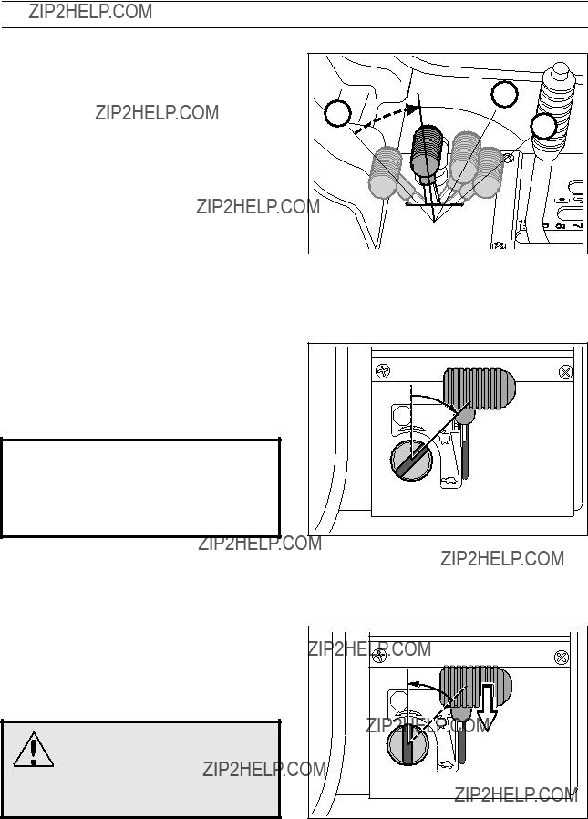
Parking brake
The parking brake is applied as follows:
1.Press down the brake pedal.
2.Press in the lock button on the steering column.
3.Release up the brake pedal while holding the button pressed.
The lock on the parking brake automatically disconnects when the brake pedal is pressed.
12 ??? English

PRESENTATION
Cutting unit
The Rider 16 can be fitted with four different cutting units.
Rear ejector - 970 mm
See ???Maintenance \ Checking the Blades??? for identification of the cutting unit.
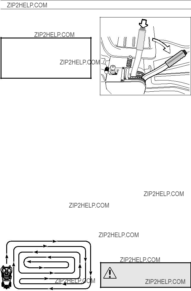
Lift lever for cutting unit
The lift lever is used to set the cutting unit in trans- port or cutting position.
If the lever is pulled back the unit will lift up and the blades will automatically stop rotating (transport position).
If the lock button is pressed and the lever is moved forward the unit will be lowered and the blades will automatically start rotating (cutting position).
The lever can also be used to temporarily regulate the cutting height, e.g. for a small mound in the lawn.
Lowering of the cutting unit (cutting position)
English ??? 13

PRESENTATION
Lever for adjustment of cutting height
With this lever the cutting height can be adjusted to 9 different positions
Unit with side/rear ejection/Combi,
BioClip unit,
Seat
The seat has a jointed attachment on the front edge and can be tipped forward.
The seat can also be adjusted lengthways.
Release the knobs under the seat and adjust it forwards or backwards to the required position.
Lock the setting with the knobs.
Fuelling
The engine should be run on 85 octane (or higher) unleaded petrol/gasoline (no added oil). Environmentally adapted alkylate fuel is also recommended.
WARNING! Petrol/gasoline is highly
inflammable. Observe care and fill up with fuel outdoors (see safety instructions).
14 ??? English
DRIVING
???Read the safety instructions and information on the location and function of the controls before starting (see pages
???Conduct daily maintenance before starting (see maintenance schedule on page 20).
Adjust the seat to the required position.
Starting the engine
1.Lift up the cutting unit by pulling the lever backwards to locked position (transport posi- tion).
2.Apply the parking brake. This is done as follows:
???Press down the brake pedal (1).
???Press in the lock button on the steering column (2).
???Release the brake pedal while the button is held pressed.
The parking brake lock disconnects automati cally when the brake pedal is pressed down.
 1
1 
Cold engine:
3.Push the throttle control to position 3 (choke position). In this position the engine receives a richer mixture so that the engine starts more easily.
DRIVING
Warm engine:
4.Set the throttle control midway between position 1 and 2.
5. Turn the ignition key to start position.
IMPORTANT INFORMATION
Do not run the starter for more than about 5 seconds at a time. If the engine does not start, wait about 10 seconds before trying again.
6.When the engine has started release the ignition key to neutral position.
Push the throttle control to the required speed. For cutting 3/4 to full throttle.
WARNING!
Never run the engine indoors, in enclosed or poorly ventilated areas. The exhaust fumes contain toxic carbon monoxide.
16 ??? English

To drive forwards: press down pedal (1).
To reverse: press down pedal (2).
3.Select the required cutting height
To obtain a uniform cutting height it is important that the tyre pressures are equal on both front wheels (60 kPa).
English ??? 17
DRIVING
4.Push in the lock button on the lift lever and lower down the cutting unit.
IMPORTANT INFORMATION
The
Cutting tips
???Localise and mark stones and other fixed objects to avoid collision.
???Start with a high cutting height and reduce down until the required cutting result are obtained.
???The cutting results are best with a high engine speed (fast rotating blades) and low driving speed (slow moving machine). If the grass is not too high and thick, the driving speed can be increased without noticeably depreciating the mowing result.
Mowing pattern
???The best lawns are achieved if the grass is cut often. Mowing becomes more uniform and the grass cuttings become more evenly distributed over the surface. The total time consumption is not greater since it is possible to select a higher driving speed without inferior mowing results.
???Avoid mowing a wet lawn. The mowing results are inferior since the wheels sink down into the soft lawn.
???Wash down the underside of the cutting unit with water after use. Do not use a high pressure jet. Put the cutting unit in the service position while doing this.
???If you use the BioClip unit it is important to mow the grass regularly.
WARNING!
Clear the lawn from stones and other object which can be thrown out by the blades.
18 ??? English
DRIVING
WARNING!
Never drive the machine on ground with a slope of more than 15??. Mow slopes upwards and downwards, never across. Avoid sudden changes in direction.
Stopping the engine
Preferably allow the engine to idle for a minute to obtain normal working temperature before stopping it if it has been working hard.
1.Lift up the cutting unit by pulling the lever back to the end position.
2.Pull back the throttle control and turn the ignition key to the STOP position.
3. When the Rider is at a standstill, press down the parking brake and push in the locking button.
Release lever
The release control must be pulled out in order for the Rider to be moved when the engine is shutoff.

MAINTENANCE
Maintenance schedule
The following is a list of the maintenance which should be conducted on the machine. For the items which are not described in these instructions go to an authorised service workshop.
1) First change after 5 hours. 2) During dusty conditions cleaning and replacement should be more frequent. 3) For daily use of the machine lubrication should be conducted twice a week. 4) Conducted by authorised service workshop.
??? = Described in these instructions.
??? = Not described in these instructions.
WARNING!
No service procedures must be conducted on the engine or cutting unit unless:
???The ignition cable is removed from the plug.
20 ??? English

MAINTENANCE
Dismantling of the machine hoods
Engine hood
The engine is accessible for servicing when the engine hood is lifted up.
Tilt the seat forward, release the rubber strap under the seat, and tilt the hood backwards.
Front hood
Release the clip on the front hood and lift off the fender.
Remove the knob (1), the screws (2 and 3) and lift off the hood.
Release the screws in the fender (2) and lift off the fender.
English ??? 21
MAINTENANCE
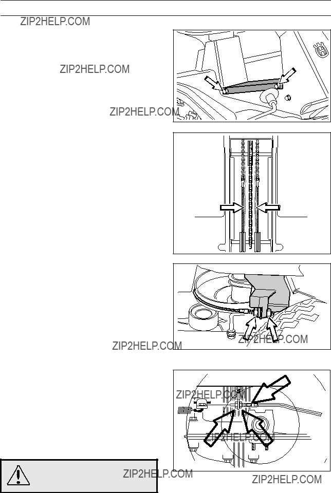
Checking and adjustment of the steering wires
The steering is controlled by means of wires.
These can in time become slack, which implies that the adjustment of the steering becomes altered.
Check and adjust the steering as follows:
1.Dismantle the
2.Check the tension of the steering wires by pushing them together as shown in the diagram. It should be possible to push them together so that the distance between them is half as much, without using unnecessary force.
3.When necessary the wires can be tensioned by tightening the adjusting nuts, one on each side of the steering rim.
Do not tension the wires too tightly, they should only be tightened up to the steering rim.
Check the wire tension on completion of the adjustment as per item 2.
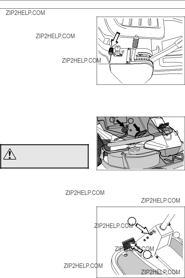
Adjusting the brake
The brake is adjusted as follows:
1.Release the lock nuts (1).
2.Tension the wire with the adjusting screw (2) until all the play in the wire is taken up.
3.Tighten the lock nuts (1).
4.The brakes should be checked again after the adjustment has been made.
WARNING!
Poorly adjusted brakes can result in reduced braking power.
22 ??? English
MAINTENANCE
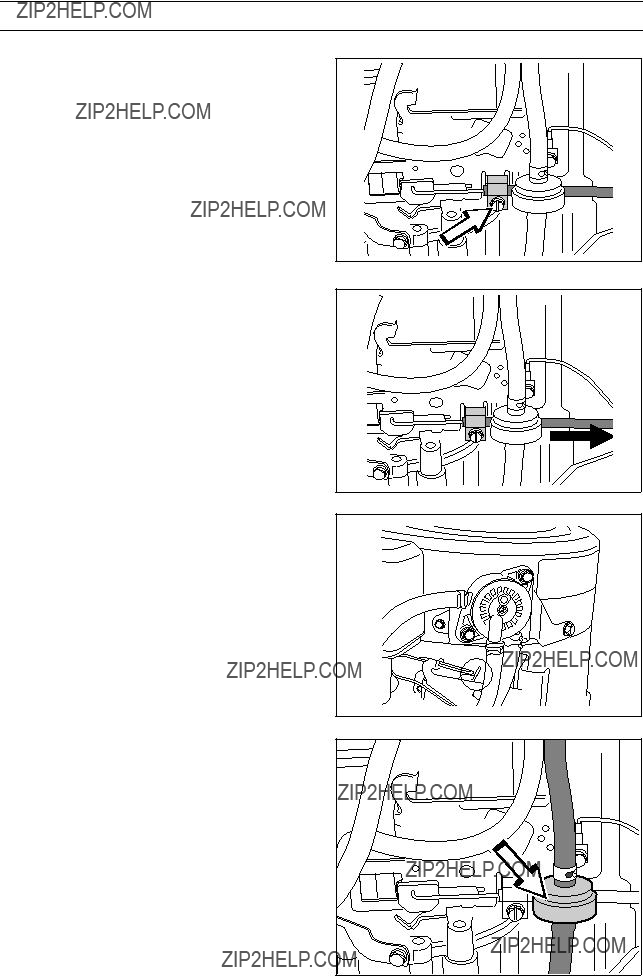
Checking and adjustment of the throttle wire
If the engine does not respond as it should do when the throttle lever is moved or if the top speed is not reached, the throttle wire may need adjusting.
1.Loosen the clamping screw (by the arrow), and slide the throttle to the choke position.
2.Pull the throttle wire???s casing as far as possible to the right and check that the choke is fully actuated.
3.Tighten the clamping screw.
4.Pull back the throttle to the full throttle position and check that the choke is no longer actuated.
Replacement of the fuel filter
Replace the pipe fitted fuel filter every 100 running hours (once per season) or more frequently if it is clogged.
Replace the filter as follows:
1.Fold open the engine cover as described on page 19.
2.Move the hose clips away from the filter. Use a pair of flat pliers.
3.Pull off the filter from the hose ends.
4.Press in the new filter on the hose ends. If necessary soap solution can be applied on the filter ends to simplify fitting.
5.Push the hose clips back on the filter.
MAINTENANCE
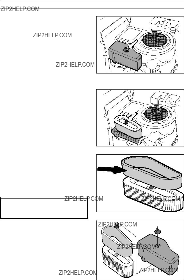
Replacing the air filter
If the engine seems to lack power or goes irregularly the reason may be that the air filter is clogged.
It is therefore important to replace the air filter at regular intervals (see ???Maintenance schedule??? on page 20 for correct service interval).
1. Fold open the engine cover.
2.Remove the air filter housing???s plastic cover by releasing the
3.Remove the
4.Pull off the foam plastic
Squeeze it dry in a clean cloth.
Drench it with new engine oil. Wrap the filter in an absorbent cloth and squeeze out excess oil.
Replace the paper filter if it is clogged with dirt.
IMPORTANT INFORMATION
Do not use compressed air to clean the paper filter.
5.Fit the air filter as follows:
Push the
Fit the paper filter with
Replace the plastic cover oven the air filter housing and tighten the
24 ??? English

MAINTENANCE
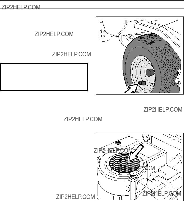
Checking of the fuel pump???s air filter
Check regularly that the fuel pump???s air filter is free from dirt.
The filter can when necessary be cleaned with a brush.
Check the level of the battery acid
Check that the level of the battery acid lies between the markings. Top up the cells with only distilled water.
WARNING!
Procedures on contact with acid
External: Rinse well with plenty of water.
Internal: Drink large quantities of water or milk. Contact a doctor as soon as possible.
Eyes: Rinse well with plenty of water. Contact a doctor as soon as possible.
Batteries emit explosive gas. Sparks, flames and cigarettes must absolutely not be brought into the vicinity of the battery.
Ignition system
The engine is equipped with an electronic ignition system. Only the spark plug requires maintenance.
For recommended spark plug, see chapter ???Technical data???.
IMPORTANT INFORMATION
Fitting the wrong spark plug type can damage the engine.
1.Remove the ignition cable shoe and clean around the spark plug.
2.Remove the spark plug with a 13/16" (21 mm) spark plug socket wrench.
3.Check the spark plug. Replace the spark plug if the electrodes are burned or if the insulation is cracked or damaged. Clean the spark plug with a steel brush if it is to be reused.
4.Measure the electrode gap with a gapping tool. The gap should be 0.75 mm/0.030". Adjust as necessary by bending the side electrode.
5.Reinsert the spark plug, turning by hand to avoid damaging the threads.
IMPORTANT INFORMATION
Inadequately tightened spark plugs can cause overheating and damage the engine. Tightening the spark plug too much can damage the threads in the cylinder head.
6.After the spark plug is seated, tighten it using a spark plug wrench so that the washer is compressed. A used spark plug should be turned
7.Replace the ignition cable shoe.
English ??? 25

MAINTENANCE
Inspecting the safety system
The Rider is equipped with a safety system that prevents starting or driving under the following conditions:
The engine should only be possible to start when the cutting unit is in its raised position and the hydrostat pedals are in the neutral position.
The driver does not need to be seated in the driver???s seat.
Make daily inspections to ensure that the safety system works by attempting to start the engine when one of the conditions is not met. Change the conditions and try again.
Check that the engine stops if you temporarily move out off the driver???s seat while the cutting unit is lowered or the hydrostat pedals are not in the neutral position.
26 ??? English
MAINTENANCE
Checking the tyre pressure
The tyre pressure should be 60 kPa (0.6 kp/cm2) all round.
To improve driving the pressure on the rear tyres can be reduced to 40 kPa (0.4 kp/cm2).
The maximum tyre pressure is 100 kPa (1.0 kp/cm2).
IMPORTANT INFORMATION
Different tyre pressures on the front tyres will result in the blades cutting the grass at different heights.
Check the engine???s cooling air intake
Fold open the engine cover as described on page 19.
Check that the cooling intake is free from leaves, grass and dirt.
If the cooling intake is blocked this will interfere with the cooling of the engine, which can damage the engine.
English ??? 27
MAINTENANCE
Fitting the cutting unit
1.Place the Rider on a flat surface and apply the parking brake. Check that the lever for setting the cutting height is in the lowest position.
Make sure the support wheels are fitted to the cutting unit (1).
2.Grasp the handle at the front (BioClip 90) or hold the frame of the cutting unit (2) and slide the unit underneath the rider mower, making sure that the tongue on the cutting unit (3) engages correctly.
3.Insert the bolt and secure it with a locking pin.
WARNING!
Observe caution to avoid trapping your hand.
4.Press down the frame and insert the pin. Fit the drive belt around the drive wheels of the cutting unit.
5.Hook up the height adjustment strut.
6.Fit the front cover.
7.Secure the collet???s spring, see ring in the diagram below.
Installing BioClip 90
In order to install BioClip 90 the drive belt support wheel must first be removed.
1.Release the tensioning wheel???s spring, see ring in the diagram.
2.Remove the locking pin (1) that is located next to the support wheel.
3.Screw off the nut and washer (2) under the centre of the support wheel. Remove the screw and support wheel.
4.Fit the cutting unit according to the instructions above.
1
 2
2
28 ??? English
MAINTENANCE
Checking and adjustment of the cutting unit???s ground pressure
To achieve the best cutting results the cutting unit should follow the underlying surface without pres- sing too hard against it.
The pressure is adjusted with a screw on each side of the machine.
1.Check the air pressure in the tyres 60 kPa (0.6 kp/cm2).
2.Place the Rider on a flat surface.
3.Put the lifting lever in the mowing position.
4.Place a set of bathroom scales under the cutting unit???s frame (front edge) so that it rests on the scales. If necessary a block can be placed between the frame and scales so that the support wheels do not bear any weight.
5.Adjust the unit???s ground pressure by screwing in or out the adjusting screws located behind the front wheels on both sides.
The ground pressure should be between 12 and 15 kg.
Checking the cutting unit???s parallelism
Check the parallelism of the cutting unit as follows:
1.Check the air pressure in the tyres 60 kPa (0.6 kp/cm2).
2.Place the machine on a level surface.
3.Put the lifting lever in the mowing position.
4.Measure the distance between the ground and the front and rear edges of the cutting unit hood. The cutting unit should slope forwards slightly so that the rear edge is

MAINTENANCE
Adjusting the parallelism of the cutting unit
1.Remove the front hood and
2.Undo the nuts on the lift strut.
3.Unscrew the strut (anticlockwise) to lower the rear edge of the hood.
Screw the strut in (clockwise) to raise the rear edge of the hood.
4.Tighten the nuts after adjustment.
5.On completion of the adjustment the unit???s parallelism should be
6.Fit the
Removing the cutting unit
WARNING!
Wear protective glasses when dismantling the cutting unit. The spring which tensions up the belt can go off and cause personal injury.
1.Carry out points
2.Remove the bolt (3) and lift off the cutting unit.
Fitting of the cutting unit takes place in the reverse order to removal. See page 28 for details of how to fit the BioClip 90.
When assembling: Make sure that the unit???s ???lug??? enters the loop correctly on the underside of the machine.
30 ??? English

MAINTENANCE
Replacing the cutting unit belts
Belt change on BioClip 103
There are two versions of BioClip 103. Version 1 has one toothed belt and version 2 has two. The toothed belts drive the blades and synchronise their rotation. The belts are located under a cover on top of the cutting unit.
1.Remove the cutting unit, see page 30.
2.Remove the front bolt from the parallel strut and tip the strut backwards. Push the height adjustment strut forwards.
3.Loosen the two bolts holding the protective hood and then lift off the hood.
Useful hint: Mark the positions of the blades on the respective pulley using a
4.Version 1:
Loosen the three bolts 1/2 - 1 turn. Press the sides of the belt together to give maximum slack and tighten one of the bolts. Replace the belt and tighten as shown (see decal on cover). Set the blades at 90?? to each other and loosen the bolt again. The spring ensures the correct belt tension. Check the positions of the blades again and adjust if necessary by repositioning the belt on the teeth. Tighten the three bolts to 45 Nm.
4.Version 2:
Loosen the nuts on the eccentric plate and turn this away.
Loosen the four nuts (see diagram) holding the outer blade bearing enough so that the bearing can be moved.
Slide the blade bearing in towards the centre bearing and pry off the upper belt.
Repeat the procedure for the lower belt.
WARNING!
Wear gloves to protect your hands when working with the blades.
BioClip 103 Version 1 and 2
BioClip 103 Version 1 and 2
BioClip 103 Version 1
BioClip 103 Version 2
English ??? 31

MAINTENANCE
5.Version 2:
Assembly: First fit the lower belt and then the upper belt.
Ensure the blades are positioned as set out in the diagram, at 90 degrees to each other, otherwise the belts must be adjusted. When the blade bearings are loose the belts can be moved around to the next tooth.
Tighten the nuts enough so that the bearings rest against the cutting hood but still can be moved.
Tension the belt by turning the eccentric adjuster on top of the cutting hood. Tighten the nut.
Tighten all nuts on the blade bearings.
6.Version 2:
When the belt can be moved 7 mm inwards using a force of 10 N the belt is adjusted correctly.
7.Version 1 och 2:
Fit the protective cover over the belts and replace the parallelism arm.
Belt replacement on BioClip 90
The BioClip 90 is driven by a toothed belt that synchronises rotation of the blades. The belt is located under the cover of the cutting unit.
When changing the belt on a BioClip 90 follow steps
Belt change on cutting unit with side or rear ejection and Combi 112
On these cutting units with
1.Remove the cutting unit, see page 30.
2.Undo the bolt on the lift strut and the two screws on the cover. Lift the cover off the cutting unit.
3.Loosen the spring that tensions the
Simply reverse the procedure to fit the new belt.
IMPORTANT INFORMATION
The blades on a BioClip unit should be set at 90 degrees to each other. In all other cases the blades can collide and cause serious damage to the cutting unit.
32 ??? English

MAINTENANCE
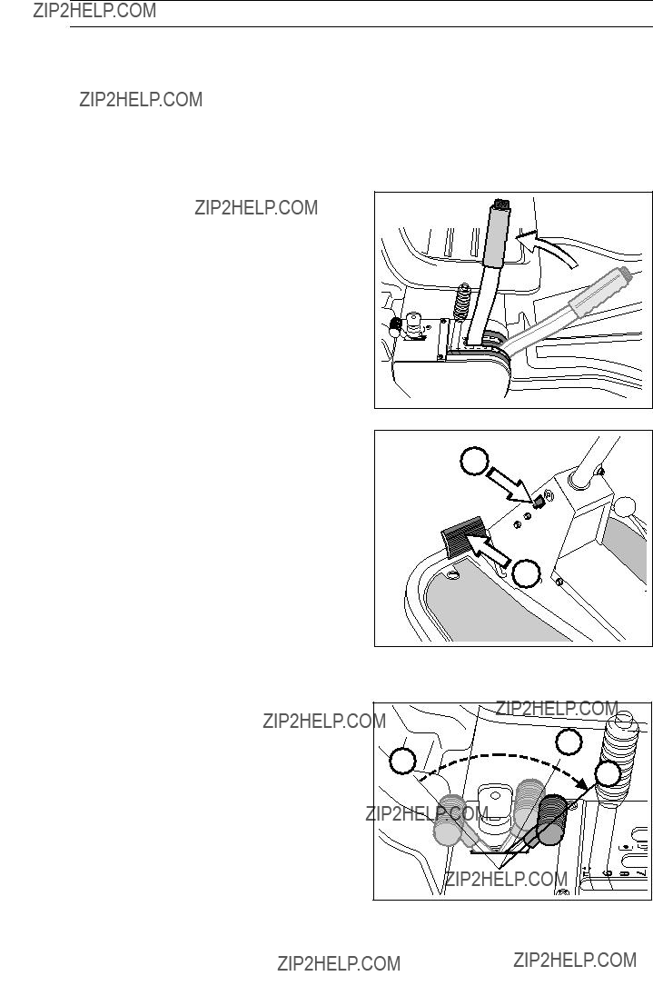
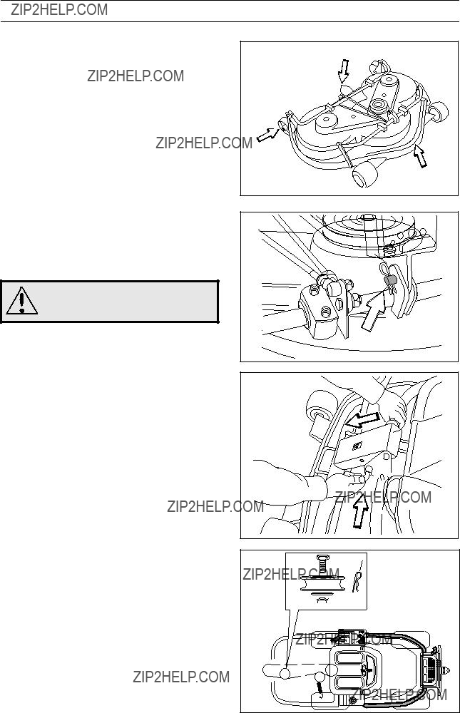
Service position for cutting unit
The cutting head can be placed in the service position to provide easy access for cleaning, repairs and servicing. In the service position the cutting unit is raised and locked in the vertical position.
Placing in service position
1.Position the machine on flat ground. Apply the parking brake (1). Adjust the cutting unit to the lowest cutting height and lower the cutting unit.
P
1
2.Remove the front hood by removing the pin. (There are complete instructions on using the service position inside the front hood).
3.Remove the two support wheels from under the front hood.

MAINTENANCE
4.Fit the support wheels on either side of the rear of the cutting unit.
WARNING!
Wear protective glasses when dismantling the cutting unit. The spring which tensions up the belt can go off and cause personal injury.
5.Disengage the spring from the drive belt tensioning wheel.
6.Move the cutting height lever to the lower position.
7.Place a foot on the front edge of the cutting unit near the wheel and raise the front edge of the unit to make it easier to remove the lift strut. Engage the strut in the holder.
34 ??? English
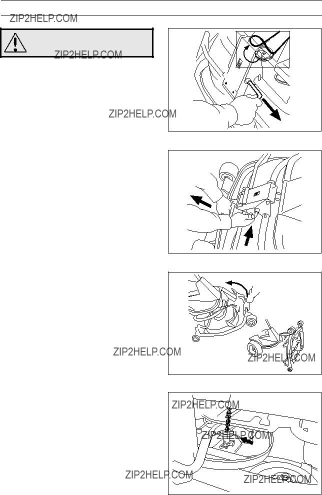
MAINTENANCE
WARNING!
Observe caution to avoid trapping your hand.
8.Lift off the drive belt (1). Then pull out the pin
(2).
2
9. Pull the frame forwards and refit the pin.
10.Grasp the front edge of the cutting unit, pull out and raise into the service position.
If the cylindrical bolt, which is now holding the cutting unit is removed, the cutting unit can be lifted off.
Restoring from service position
To leave the service position, reverse the procedures set out in ???Placing in the service position???. Make sure that the cutting unit???s ???lug??? enters the loop correctly on the underside of the machine, see diagram.
MAINTENANCE
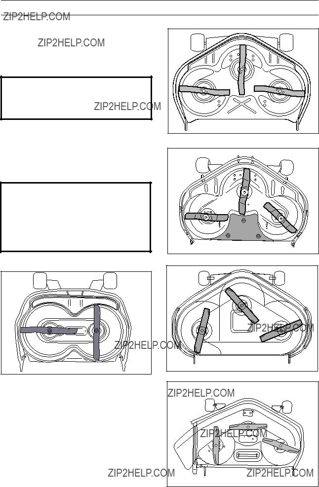
Checking the blades
To achieve the best mowing results it is important that the blades are undamaged and
Check that the blades??? attachment screws are tight.
IMPORTANT INFORMATION
Replacing or sharpening the blades should be conducted by an authorised service workshop.
The blades should be balanced after sharpening.
Damaged blades should be replaced when hitting obstacles that result in a breakdown. Let the servicing dealer judge whether the blade can be repaired/ground or must be discarded.
IMPORTANT INFORMATION
BioClip units 90 and 103 should always have the blades in the relative position shown in the diagrams with an angle of 90?? between the blades. Otherwise the blades can go against each other and damage the unit.
BioClip 90
Cutting unit with side ejection
36 ??? English
MAINTENANCE
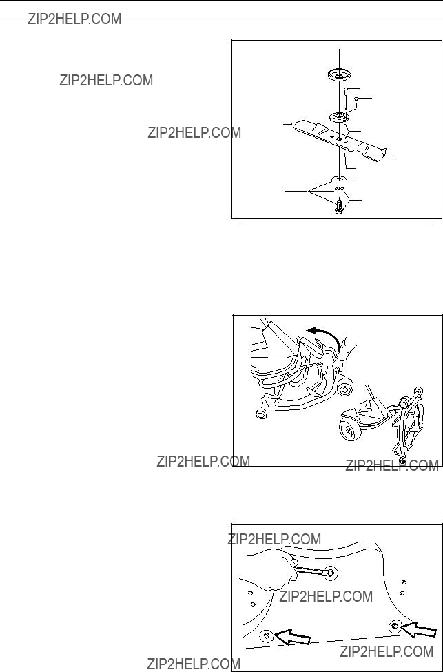
Replacing the
The blades are fitted with a
Only use original spare parts. A set containing a blade,
1.Put the unit in the service position, see ???Placing in the service position???.
2.Remove the blade (2A) by removing the blade bolt with washer and friction washer (2B).
3.Remove the remains of the broken
4.Make sure the contact surfaces (4) on the blade and the blade mounting are free from metal. Clean if necessary.
5.Fit one new
6.Fit the blade (6), make sure it is fitted as illustrated.
7.Fit a new friction washer (7) with the concave face turned towards the blade.
8.Fit the blade bolt with washer (8). Tightening torque
Removal of BioClip plug (Combi)
To change a Combi unit from BioClip function to cutting unit with rear ejection, remove the BioClip plug located under the unit with three screws.
1.Put the unit in the service position, see "Placing in the service position".
2.Remove the three screws holding the BioClip plug, and remove the plug.
3.Tip: Fit three
4.Replace the unit in normal position.
Fit the BioClip plug in the reverse order.
5
3
2A
4
6
4
 7 2B
7 2B 
8
Service position
Removal of BioClip plug
English ??? 37

LUBRICATION
Check the engine???s oil level
Check the oil level in the engine when the machine is horizontal.
Fold open the engine cover.
Release the dip stick and pull out. Wipe off the oil and insert again.
The dip stick must be fully screwed down.
Now release the dip stick again and pull out. Check the oil level.
The oil level should lie between the markings on dip stick. If the level approaches the ADD mark, top up with oil to the FULL mark.
The oil is filled in the same hole for the dip stick
Use engine oil SAE 30 or SAE 10W/30, class SF- CC.
The total oil volume in the engine is 1.2 litres.
Changing the oil
The oil should be changed for the first time after 5 hours of running time. Thereafter it should be changed every 25 hours of running time.
WARNING!
Engine oil can be very hot if it is drained off directly after the engine is stopped. Therefore allow the engine to cool down first.
1.Place a receptacle under the engine???s drain plug, located on the
2.Remove the dip stick and drain plug.
3.Let the oil run out into the receptacle.
4.Fit the drain plug and tighten.
5.Fill up with oil to the FULL mark on the dip stick. The oil is filled in the same hole for the dip stick. Use engine oil SAE 30 or SAE 10W/30, class
Use engine oil with min. API SF quality and SAE 30 or SAE 10W/30 viscosity grade. The oil volume in the engine is 1.2 litres.
6.Run the engine warm and then check that there is no leakage from the drain plug.
IMPORTANT INFORMATION
Used engine oil is hazardous to health and environment and must in accordance with the law not be poured out on the ground or in the nature, and must be handed in to a workshop or other designated station for treatment. Avoid skin contact, wash with soap and water in the event of spillage.
38 ??? English
LUBRICATION
Check the transmission???s oil level
1.Remove the transmission cover. Loosen both screws (one on each side) and lift off the trans- mission cover.
2.Check that there is oil in the transmission???s oil tank. Fill if necessary with engine oil SAE 10W/ 30 (class
Lubricating the belt adjuster
The belt adjuster should be lubricated regularly using good quality molybdenum disulphide grease*.
1 nipple from the
With daily use lubrication should be conducted twice a week.
General lubrication
All joints and bearings are lubricated on manufacture with molybdenum sulphide grease.
The machine should be lubricated regularly, and twice a week when used daily.
* Grease from
English ??? 39

TROUBLE SHOOTING SCHEDULE
40 ??? English

STORAGE
Winter storage
At the end of the season the machine should immediately be put in order for storage, also if it is going to stand idle for more than 30 days. Fuel which is left to stand for long periods (30 days or more) can leave tacky deposits which can block the carburettor and interfere with the engine.
Fuel stabiliser is an acceptable alternative to avoid tacky deposits during storage. If alkylate petrol (Aspen) is used stabiliser is not necessary since this fuel is stable. However, one should avoid changing from standard to alkylate petrol since sensitive rubber parts can harden. Add stabiliser to the fuel in the tank or the storage container. Always use the mixing ratios indicated by the manufacturer. Run the engine for at least 10 minutes after adding the stabiliser so that it will reach the carburettor. Do not empty the fuel tank and carburettor if stabiliser has been added.
WARNING!
Never place an engine with fuel in the tank indoors or in poorly ventilated areas where petrol fumes can come into contact with naked flames, sparks or pilot flames in boilers, hot water heaters, or
drying cabinets, etc. It is highly inflammable and negligent usage can cause severe person injury and material damage. Drain off the fuel in an approved container outdoors and well clear of naked flames. Never use petrol for cleaning purposes. Use degrea- sing agents and hot water instead.
To put the machine in order for storage follow these instructions:
1.Carefully clean the machine, especially under the cutting unit.
2.Inspect the machine for worn or damaged parts and tighten loose screws and nuts.
3.Change the oil, and take care of the waste oil.
4.Empty the fuel tank. Start the engine and run it until the carburettor is emptied of fuel.
5.Remove the spark plug and pour about a tablespoon of engine oil in the cylinder. Turn over the engine so that the oil is evenly distributed and then refit the spark plug.
6.Grease all grease nipples, joints and axles.
7.Remove the battery. Clean it, charge it, and store it is a cool place.
8.Store the machine is a clean and dry place and cover it over for extra protection.
Service
When ordering spare parts state the purchase year, model, type, and serial number.
Always use genuine parts.
Annual inspection or trimming by an authorised service workshop is a good way of getting the best out of your machine the next season.
English ??? 41

When this product is worn out or no longer used it should be returned to the dealer or other appropriate body for recycling.
We reserve the right to change technical specifications without prior notice.
Note that no legal claims are valid on the basis of information in this manual.
Use only genuine parts for repairs. The warranty is not valid if non genuine parts are used.
42 ??? English

EU declaration of conformity (Only applies to Europe)
Husqvarna AB,
-of June 22, 1998 ???relating to machinery??? 98/37/EC, annex IIA.
-of May 3, 1989 ???relating to electromagnetic compatibility??? 89/336/EEC, and applicable supplements.
-of May 8, 2000 ???relating to the emission of noise to surroundings??? 2000/14/EC.
Information regarding noise emissions and the mowing width, see the Technical Data.
The following harmonised standards have been applied:
The registered body 0404, SMP Svensk Maskinprovning AB, Fyrisborgsgatan 3,
Huskvarna January 3, 2002
Roger Andersson, Development Manager/Garden Products
English ??? 43

44 ??? English

SERVICEJOURNAL
English ??? 45

SERVICEJOURNAL
46 ??? English

SERVICEJOURNAL
English ??? 47

SERVICEJOURNAL
??+H$|??6k??
English ??? 49
114 00
??+H$|??6k?? 2002W09