HUV 5420 DX
CE Mark Diesel Vehicle
Owner???s Manual
[Refer to back cover for applicable build code range]
HUV 5420 DX
CE Mark Diesel Vehicle
Owner???s Manual
[Refer to back cover for applicable build code range]

NOTICE
This manual is valid for vehicles manufactured in the build code range provided on the back cover of this manual. If the vehicle build code is different from that shown on the back cover of this manual, please contact your nearest dealer or go to www.husqvarna.com to retrieve the proper owner???s manual for the vehicle. See also Model Identification in this manual.
Your authorized representative checked the vehicle before it was delivered to you and will provide you a copy of the completed vehicle warranty registration form. No other warranties, express or implied, are contained herein.
Husqvarna is not liable for errors in this manual or for incidental or consequential damages that result from the use of the material in this manual.
This manual contains proprietary information that is protected by copyright. All rights are reserved. No part of this manual may be photocopied, reproduced, or translated to another language without the written consent of Husqvarna, Inc.
The information contained in this document is subject to change without notice.
Husqvarna reserves the right to make design changes to vehicles without obligation to make these changes on units previously sold.
These utility vehicles are
If in English, this manual is the Original Instructions provided by the manufacturer. If in any language other than English, this manual is a translation of the Original Instructions.
Copyright ?? 2009 Husqvarna AB (publ). All rights reserved. Husqvarna and other product and feature marks are trademarks of Husqvarna Group.

FOREWORD
Thank you for choosing Husqvarna, the name most widely recognized as the industry leader in vehicle efficiency and
Your comfort and safety are important to us, so we urge you to read and follow the
Husqvarna products are backed by a customer support system designed to offer you fast, courteous service. In the event your Husqvarna vehicle needs repairs or service, please contact your local authorized Husqvarna dealer or distributor; he will be able to provide technical advice, perform warranty work, and sell parts and service manuals.
For the name and address of the authorized Husqvarna dealer or distributor nearest you, logon to our web site at www.husqvarna.com.
We hope you will consider this owner???s manual a permanent part of your Husqvarna vehicle. If you sell the vehicle, please include the manual so that the next owner will have the important operating, safety, and maintenance information it contains.
Page 2 HUV 5420 DX


Safety Decal and Feature Identification
SAFETY DECAL AND FEATURE IDENTIFICATION
The following pages contain safety decal and feature identification information. For detailed information on specific features, read the appropriate section in this manual.
HUSQVARNA HUV 5420 DX DIESEL CE MARK VEHICLES
8
3
6
4
2
7
Page 4 HUV 5420 DX

Safety Decal and Feature Identification
HUSQVARNA HUV 5420 DX DIESEL CE MARK VEHICLES
4
6
3
5
9
1
2

Safety Decal and Feature Identification
HUSQVARNA HUV 5420 DX DIESEL CE MARK VEHICLES
3
2
Page 6 HUV 5420 DX
Practice Safety
PRACTICE SAFETY
399
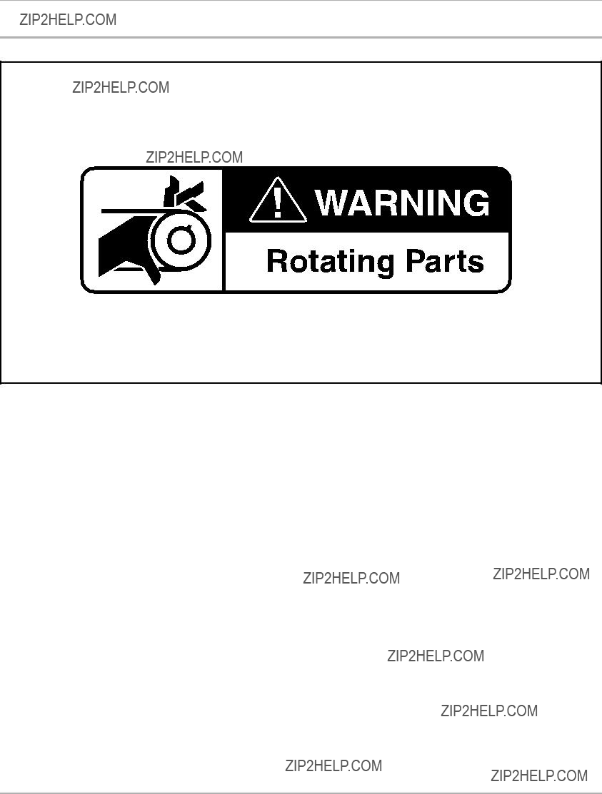
Figure 1 Practice Safety
Safety signs like you see above may at first seem shocking, but their impact is mild compared with the reality of severe personal injury.
Your safety and satisfaction are of the utmost importance to us. That is why before operating the vehicle, we urge you to review the information in this manual. Understand and become familiar with the DANGER, WARNING, and CAUTION statements and procedures it contains, along with the safety decals that are affixed to your vehicle.
Take time to understand the language of safety. It is a language that can save your life.

Safety Details
SAFETY DETAILS
 WARNING
???This owner???s manual should be read completely before attempting to drive or service the vehicle. Failure to follow the instructions in this manual could result in property damage, severe personal injury, or death.
It is important to note that some vital statements throughout this manual and on the decals affixed to the vehicle are preceded by the words DANGER, WARNING, or CAUTION. For your protection, we recommend that you take special notice of these safety precautions. Safety precautions are essential and must be followed.
If any of the operation or warning decals on the vehicle become damaged, have been removed, or cannot be easily read, they should be replaced immediately to avoid possible property damage, personal injury, or death. Contact your dealer.
 DANGER
??? A DANGER indicates an immediate hazard that will result in severe personal injury or death.
 WARNING
??? A WARNING indicates an immediate hazard that could result in severe personal injury or death.
 CAUTION
???A CAUTION with the safety alert symbol indicates a hazard or unsafe practice that could result in minor personal injury.
CAUTION
???A CAUTION without the safety alert symbol indicates a potentially hazardous situation that could result in property damage.
GENERAL WARNINGS
The following safety statements must be heeded whenever the vehicle is being operated, repaired, or serviced.
See Safety Decal and Feature Identification on page 4. Other specific safety statements appear throughout this manual and on the vehicle.
 DANGER
???Battery ??? Explosive gases! Do not smoke. Keep sparks and flames away from the vehicle and service area. Ventilate when charging or operating vehicle in an enclosed area. Wear a full face shield and rubber gloves when working on or near batteries.
???Diesel ??? Flammable! Explosive! Do not smoke. Keep sparks and flames away from the vehicle and service area. Service only in a
???Do not operate engine in an enclosed area without proper ventilation. The engine produces carbon monoxide, which is an odorless, deadly poison.
???The vehicle will not provide protection from lightning, flying objects, or other
Page 8 HUV 5420 DX
General Warnings
 WARNING
???Follow the procedures exactly as stated in this manual, and heed all DANGER, WARNING, and CAUTION statements in this manual as well as those on the vehicle.
???Do not leave children unattended on vehicle.
???Children requiring a child safety seat must not ride on the vehicle. Comply with state and local laws pertaining to child safety.
???The driver and passenger must be restrained at all times with the seat belts provided to help prevent injury in the event of sudden braking, collision, or
???No more than one person per bucket seat at one time. No more than two persons per bench seat at one time. Do not allow people to ride in any part of the vehicle that is not equipped with a seat and a seat belt. Do not allow a passenger to hold a child in his or her lap while the vehicle is moving.
???Prior to leaving the vehicle unattended or servicing the vehicle, set the park brake, place the Forward/Reverse handle in the NEUTRAL position, turn the key switch to the OFF position, and remove the key. Chock the wheels when servicing the vehicle.
???Improper use of the vehicle or failure to properly maintain it could result in decreased vehicle performance, severe personal injury, or death.
???Any modification or change to the vehicle that affects the stability or handling of the vehicle, or increases maximum vehicle speed beyond factory specifications, could result in severe personal injury or death.
???Check the vehicle for proper location of all vehicle safety and operation decals and make sure they are in place and are easy to read.
???For vehicles with cargo beds, remove all cargo before raising the bed or servicing the vehicle. If the vehicle is equipped with a prop rod, ensure that it is securely engaged while bed is raised. Do not close bed until all persons are clear of cargo bed area. Keep hands clear of all crush areas. Do not drop cargo bed; lower gently and keep entire body clear. Failure to heed this warning could result in severe personal injury or death.
???Only trained technicians should service or repair the vehicle. Anyone doing even simple repairs or service should have knowledge and experience in electrical and mechanical repair. The appropriate instructions must be used when performing maintenance, service, or accessory installation.
???To avoid unintentionally starting the vehicle, disconnect battery. See Disconnecting the Battery ??? Diesel Vehicles on page 10.
???Frame ground ??? Do not allow tools or other metal objects to contact frame when disconnecting battery cables or other electrical wiring. Do not allow a positive wire to touch the vehicle frame, engine, or any other metal component.
???Wear safety glasses or approved eye protection when servicing the vehicle. Wear a full face shield and rubber gloves when working on or near batteries.
???Do not wear loose clothing or jewelry such as rings, watches, chains, etc., when servicing the vehicle.
???Use insulated tools when working near batteries or electrical connections. Use extreme caution to avoid shorting of components or wiring.
???When servicing the vehicle with part of the vehicle on jack stands, do not operate the engine with the Forward/Reverse handle in either the FORWARD or REVERSE position. The
DISABLING THE VEHICLE
1.Set the park brake.
2.Turn the key switch OFF and remove the key.
3.Place the Forward/Reverse control in the NEUTRAL position.
4.In addition, chock the wheels if servicing or repairing the vehicle.
General Warnings
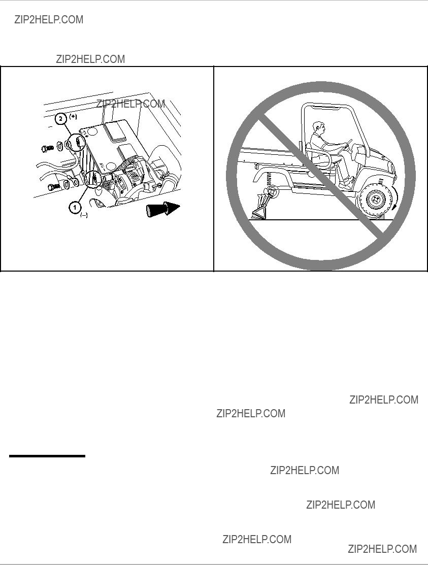
DISCONNECTING THE BATTERY ??? DIESEL VEHICLES
1.Disable the vehicle. See Disabling the Vehicle on page 9.
2.Disconnect the battery cables, negative
1.Remove negative battery cable.
2.Remove positive battery cable. Connect battery cables in reverse order.
CONNECTING THE BATTERY ??? DIESEL VEHICLES
1.Connect the battery cables, positive (+) cable first.
2.Tighten battery terminals to 80
3.Coat terminals with Battery Terminal Protector Spray (P/N 603 00
RECYCLING
 WARNING
???
Page 10 HUV 5420 DX
General Information
1403
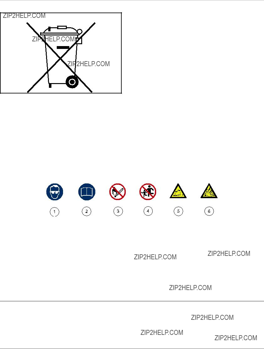
Figure 4 Dispose of
INTERNATIONAL SAFETY SYMBOLS ON BATTERIES
Anyone using, repairing, or servicing the vehicle must understand and heed the safety symbols on the vehicle battery or batteries.
1642
Figure 5 International Safety Symbols on Batteries
GENERAL INFORMATION
This manual includes operating procedures, maintenance, and regular servicing information for all diesel Husqvarna HUV 5420 DX vehicles. All operating procedures, maintenance, and regular servicing are identical unless otherwise noted.

Model Identification
MODEL IDENTIFICATION
The serial number of each vehicle is printed on a bar code decal mounted either below the passenger side cup holder or above the accelerator or brake pedal (Example:
The two letters (1) at the beginning of the serial number indicate the vehicle model. The following four digits (2) indicate the model year and production week during which the vehicle was built. The six digits (3) following the hyphen represent the unique sequential number assigned to each vehicle built within a given model year. See following NOTE.
NOTE: Have the vehicle serial number available when ordering parts or making inquiries.
Build Code: The build code (4) is a
Figure 6 Serial Number Decal
CONTROLS AND INDICATORS
See General Warnings on page 8.
 WARNING
???Before allowing anyone to drive the vehicle, make sure the driver is familiar with all controls and operating procedures.
???Do not tamper with the high idle speed setting on the diesel vehicle. Doing so will void the warranty, as well as damage the engine and other components, and could result in property damage, personal injury, or death due to unsafe speeds.
???Do not shift the Forward/Reverse handle while the vehicle is in motion.
???Engine must be at idle before shifting the Forward/Reverse handle. Failure to do so may result in injury to inattentive passengers and (or) damage to the vehicle.
???To avoid unintentionally starting or rolling the vehicle, set the park brake, place the Forward/Reverse handle in the NEUTRAL position, turn the key switch to the OFF position, and remove the key when leaving the vehicle.
Page 12 HUV 5420 DX

Controls and Indicators
Figure 7 Instrument Panel ??? Diesel Vehicles
 WARNING
??? Moving parts! Keep clear of the engine compartment while the engine is running.
CAUTION
???Do not shift the Forward/Reverse handle while the accelerator pedal is pressed. Shift the handle only when the vehicle is at a complete stop and the engine is at idle. Failure to heed this caution could result in damage to the transmission.
NOTE: The key can be removed only when the key switch is in the OFF position.
KEY SWITCH ??? DIESEL VEHICLES
The key switch (7) is mounted on the instrument panel to the right of the steering column (Figure 7). It has four positions: PREHEAT, OFF, ON, and START.
Use the PREHEAT feature if the temperature falls below

Controls and Indicators
FORWARD/REVERSE CONTROL
The Forward/Reverse handle (6) is located on the right side of the instrument panel (Figure 7). The handle has three distinct positions: FORWARD (A), NEUTRAL (B), and REVERSE (C). Push the handle up to operate the vehicle in the forward direction, or pull the handle down to operate the vehicle in reverse. The engine can be started only when the handle is in the NEUTRAL (middle) position. The engine must be at idle before shifting the Forward/Reverse handle.
See preceding WARNING and CAUTION.
Husqvarna vehicles operate at a reduced speed in reverse. The reverse buzzer will sound as a warning when the Forward/Reverse handle is in the REVERSE position.
HORN
The horn button is located on the on the left side of the steering column. Press the button to sound the horn. See
Safety Decal and Feature Identification on page 4.
ACCELERATOR PEDAL
The accelerator pedal (1) is the pedal farthest to the right (Figure 7).
With the engine running and the Forward/Reverse handle in the FORWARD or REVERSE position, vehicle speed will increase as the accelerator pedal is pressed. When the accelerator pedal is released, it will return to the original position and the engine will idle. See preceding WARNING and CAUTION.
BRAKE PEDAL
The brake pedal (2) is located to the immediate left of the accelerator pedal (Figure 7). To slow or stop the vehicle, press the brake pedal.
PARK BRAKE
The park brake pedal (3) is located to the left of the brake pedal (Figure 7). To engage the park brake, first apply pressure to the brake pedal, then firmly press the park brake pedal until it latches into place. To disengage the park brake, pull the park brake release handle (4) (Figure 8). See following WARNING.
 WARNING
???The park brake has multiple locking positions and should be firmly locked to prevent the vehicle from rolling.
Page 14 HUV 5420 DX

Controls and Indicators
Figure 8 Park Brake Release
STEERING ADJUSTMENT LOCK
The steering wheel position is adjustable. To adjust the steering wheel position, press down on the steering adjustment lock lever (5), then move the steering wheel to the desired position (Figure 7). While holding the steering wheel in the desired position, pull up on the steering adjustment lock lever to firmly lock the steering column in position.
See following WARNING.
 WARNING
??? Ensure that the steering wheel lock is fully engaged before operating the vehicle.
The
NOTE: Extended use of this accessory outlet can cause the battery to become heavily discharged.
LOW OIL WARNING LIGHT
The low oil warning light (9) is located on the instrument panel just to the left of the steering column (Figure 7). If the warning light comes on, oil should be checked and added to the engine as necessary before vehicle use continues. The vehicle should never be driven when the low oil warning light remains lit. If the warning light comes on and off, the vehicle may be driven, but oil should be added at the first opportunity. If the oil level is correct and the warning light remains lit, have a trained technician check the vehicle. See following CAUTION.

CAUTION
???Failure to add oil immediately when the low oil warning light stays on may result in permanent engine damage.
FUEL GAUGE/HOUR METER
The fuel gauge and hour meter (8) are housed together on the right side of the instrument panel (Figure 7). The fuel gauge operates when the key switch is in the ON position and allows the operator to monitor the fuel level in the vehicle. The hour meter operates only when the engine is running, and should be used by the trained technician to track vehicle usage and determine when periodic service procedures are required. See Periodic Service Schedule on page 30.
HEADLIGHT CONTROL
The headlight control (12) is located on the left side of the instrument panel (Figure 7). Press the headlight rocker switch to turn the headlight on or off. See following NOTE.
NOTE: Using the headlights for extended periods while the engine is either off or idling will discharge the battery.
ELECTRIC BED LIFT
Vehicles with Electric Bed Lift Option
The electric bed lift switch (13) is located on the instrument panel to the left of the key switch (Figure 7). See following NOTE.
NOTE: Remove cargo before raising the bed.
To lift the bed, push up and hold the rocker switch in the upper position. Release the switch to stop the lifting operation. To close the bed, press down and hold the switch in the lower position. The bed lift will make a loud clicking sound to signal that the bed is in the rest position.
The
 WARNING
???Allow the engine to cool before servicing the engine coolant system. Engine coolant can cause severe burns.
The Husqvarna HUV 5420 DX vehicles are equipped with a
Page 16 HUV 5420 DX

 WARNING
???The ROPS must be properly installed before operating the vehicle. Husqvarna strongly urges that the vehicle???s occupants be properly restrained at all times with the seat belts provided.
Pregnant woman: Consult your doctor for specific recommendations. The seat belt should be worn securely and as low as possible over the hips and not on the waist.
Injured person: Depending on the injury, first check with your doctor for specific recommendations.
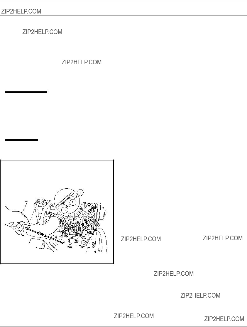
To secure the seat belt, sit up straight and well back in the seat. Pull the seat belt out of the retractor and insert the tab into the buckle. A click will be heard when the tab locks into the buckle. Position the lap belt as low as possible on the hips ??? not on the waist.
The retractor will lock the belt during a sudden stop. It also may lock if the occupant leans forward too quickly. A slow, easy motion will allow the belt to extend, and the occupant can move freely. If the seat belt cannot be pulled out of the retractor, firmly pull the belt and release it. It should then pull smoothly out of the retractor.
To release the seat belt, press the buckle release button (1) and allow the belt to retract (Figure 9). If the belt does not retract smoothly, pull it out and check for kinks or twists. Then make sure it remains free of twists as it retracts.
194
Figure 9 Release seat belt
 WARNING
???Do not operate the vehicle with the ROPS removed. Doing so could result in property damage, personal injury, or death.
???Do not remove or modify any component of the ROPS structure. Doing so will result in voiding the ROPS certification and could weaken the ROPS, resulting in serious injury or death.
???Do not operate the vehicle if the ROPS is damaged. If the ROPS is damaged, replace the structure. Do not attempt repair.
???The driver and passenger must be restrained at all times with the seat belts provided to help prevent injury in the event of sudden braking, collision, or
WARNING CONTINUED ON NEXT PAGE

Seat Latch and Adjustment
 WARNING
???In the event of a
???After inserting the tab, make sure the tab and buckle are locked and that the belt is not twisted.
???Loose fitting seat belts could increase the chance of injury due to sliding under the belt if sudden braking should occur. Keep the seat belt snug and positioned as low on the hip bone as possible.
???Use a single seat belt for one person at a time. Do not use a single seat belt for two or more people ??? this includes children.
???No more than one person per bucket seat at one time. No more than two persons per bench seat at one time. Do not allow people to ride in any part of the vehicle that is not equipped with a seat and a seat belt. Do not allow a passenger to hold a child in his or her lap while the vehicle is moving.
???The Husqvarna vehicle is not designed to meet child seat compatibility requirements. Children requiring a child safety seat must not ride on the vehicle. Comply with state and local laws pertaining to child safety.
 CAUTION
???Be careful not to damage the seat belt webbing or hardware.
???Inspect the seat belt system periodically. Check for cuts, fraying, and loose parts. Damaged parts should be replaced immediately. Do not disassemble or modify the system.
???Keep seat belts clean and dry. If cleaning is necessary, use a mild soap and lukewarm water solution. Do not use bleach, dye or abrasive cleaners as they may severely weaken the seat belts.
???Do not insert coins, clip, etc. in the buckle as this may prevent the tab from locking into the buckle properly.
???If the seat belt does not function normally, contact your dealer/distributor or trained technician immediately. Do not occupy the seat until the seat belt is repaired.
SEAT LATCH AND ADJUSTMENT
The vehicle seat(s) are hinged to allow easy access to the engine compartment. To raise the seat bottom, grasp the rear side of the seat bottom, and pull firmly in a forward/upward direction. See following WARNING.
 WARNING
??? Make sure seat hinges and latches are securely engaged before operating the vehicle. Vehicles with bucket seat option:
The
 WARNING
??? Do not adjust the
To adjust the
1.Remove the seat from the vehicle.
2.Remove the four bolts and washers from the bottom of the seat mounting plate.
3.Align the mounting plate holes with holes in the seat to achieve the desired seat position.
Page 18 HUV 5420 DX
4.Install washers and bolts, and tighten to 96
5.Install the seat. See preceding WARNING ???Make sure seat hinges and latch...???
Each Husqvarna vehicle has been thoroughly inspected and adjusted at the factory; however, upon receiving your new vehicle(s), you should become familiar with the controls, indicators, and operation. Carefully inspect each vehicle to ensure that it is in proper working condition before accepting delivery.
Use the following list as a guide to inspect the vehicle. This list should be used daily and in conjunction with the Performance Inspection on page 19 and the Periodic Service Schedule on page 30 to ensure that the vehicle is in proper working condition. Any problems should be corrected by a Husqvarna dealer/distributor or a trained technician.
???General: All the parts should be in place and properly installed. Be sure that all nuts, bolts, and screws are tight. Check hose clamps for tight fit.
???Safety and information decals: Check to ensure that all safety and information decals are in place and can be read easily. See Safety Decal and Feature Identification on page 4.
???ROPS: Check to ensure the ROPS is not damaged and all hardware is secure. See
Structure and Seat Belts on page 16.
???Seat belts: Visually inspect for cuts, fraying, and loose parts. See
???Tires: Check for proper tire pressure. Visually inspect tires for wear, damage, and proper inflation on a daily basis.
See Vehicle Specifications on page 49.
???Battery: Check electrolyte to ensure it is at the proper level (Figure 29). Check battery posts. Wires should be tight and free of corrosion, and battery should be fully charged.
???Engine: Check for proper engine oil and coolant levels and leaks. See Engine Oil on page 35. Check air filter and replace if necessary.
???Fuel: Check fuel level. See Fueling Instructions on page 42. Check fuel tank, lines, fuel cap, pump, and fuel filters for fuel leakage. Drain water from the fuel filter (diesel vehicle). See Draining Water from Fuel Filter on page 43.
???Exhaust system: Check for leaks.
???Hydraulic brakes: Check fluid level. Fill with DOT 5 brake fluid only. See Brake Fluid Reservoir on page 34. Wear in the brakes before initial vehicle operation. On a flat, open surface, accelerate the vehicle to moderate speed, then apply the brakes under modest, steady pressure. Repeat this procedure
NOTE: Perform the
??? Performance Inspection: Inspect as instructed. See Performance Inspection on page 19.
PERFORMANCE INSPECTION
After you have familiarized yourself with the vehicle controls and have read and understood the driving instructions, take the vehicle for a test drive. Use the following list, in addition to the
???Forward/Reverse shifter: Check for proper operation. See Controls and Indicators on page 12.
???Brakes: Be sure the brakes function properly. When brake pedal is fully pressed under moderate pressure, the vehicle should come to a smooth, straight stop. If the vehicle swerves or fails to stop, have the brake system

Driving Instructions
checked and adjusted as required. When the brake pedal is fully pressed under heavy pressure, the pedal should feel firm and the distance between the back of the pedal and the floorboard should be a minimum of 1.25 inches (3.2 cm). Brake adjustment must be maintained so the brake pedal cannot be pressed to the floorboard under any circumstance.
???Park brake: When latched, the park brake should lock the wheels and hold the vehicle stationary on an incline of 20% or less.
???Reverse buzzer: The reverse buzzer should sound as a warning when the Forward/Reverse handle is in the REVERSE position.
???Steering: The vehicle should be easy to steer and should not have any play in the steering wheel. Be sure the steering wheel adjustment lever is securely locked into position.
???Accelerator: After starting the engine with the key switch and placing the Forward/Reverse handle in the FORWARD position, the vehicle should accelerate smoothly to full speed as the accelerator pedal is pressed. When the pedal is released it should return to the original position, and the engine should idle. Husqvarna vehicles operate at reduced speed in reverse.
???Governor: Check maximum vehicle speed. The vehicle should operate in forward at a maximum speed of 25 mph (40 km/h) on a level surface.
???General: Listen for any unusual noises such as squeaks or rattles. Check the vehicle???s ride and performance. Have a Husqvarna dealer or a trained technician investigate anything unusual.
DRIVING INSTRUCTIONS
 WARNING
???Only licensed drivers should be allowed to drive the vehicle.
???Before allowing anyone to drive the vehicle, make sure the driver is familiar with all controls and operating procedures.
???No one under the age of 16 years should be allowed to drive the vehicle.
???No more than one person per bucket seat at one time. No more than two persons per bench seat at one time. Do not allow people to ride in any part of the vehicle that is not equipped with a seat and a seat belt. Do not allow a passenger to hold a child in his or her lap while the vehicle is moving.
???Do not allow riders in the cargo bed.
???For night use, the vehicle must be equipped with headlights, taillights, and reflectors.
???The vehicle is not specially equipped for handicapped persons:
???Be sure all passengers are capable of securing themselves in a moving Husqvarna vehicle before allowing them to ride in one.
???Be sure all persons can properly operate the vehicle prior to allowing them to drive the vehicle.
???Stop the vehicle before shifting the Forward/Reverse handle. Engine must be at idle before shifting the Forward/Reverse handle. Failure to do so may result in injury to inattentive passengers and (or) damage to the vehicle.
???To help avoid being struck, do not stand in front of or behind the vehicle.
???Do not leave children unattended on vehicle.
???Children requiring a child safety seat must not ride on the vehicle. Comply with state and local laws pertaining to child safety.
???Operate the vehicle from the driver seat only.
WARNING CONTINUED ON NEXT PAGE
Page 20 HUV 5420 DX

Driving Instructions
 WARNING
???To help prevent falls from the vehicle, remain seated with seat belt fastened and hold on to hand holds at all times. Driver should keep both hands on the steering wheel when the vehicle is in motion.
???To help prevent the possibility of serious injury, keep entire body inside the vehicle.
???To help prevent overturning the vehicle, drive slowly in turns.
???To help prevent overturning the vehicle, drive slowly straight up and down slopes. Avoid driving the vehicle on slopes exceeding 20% incline.
???Avoid stopping a loaded vehicle on a hill. If a loaded vehicle must be stopped on a hill, avoid sudden starts or rolling backwards and stopping suddenly. Failure to heed this warning could result in overturning the vehicle.
???To help avoid possible injury to inattentive passengers and (or) damage to the vehicle, avoid sudden starts, sudden stops, and abrupt turns.
???To help avoid the possibility of losing control of or overturning the vehicle, reduce speed for adverse driving conditions such as wet grass or rough terrain.
???Do not use the vehicle on public roads. It is neither designed nor intended for street use and should not be licensed for use on public roads.
???The vehicle should be driven in only specified areas by trained drivers.
???Do not drive while under the influence of alcohol, drugs, or medications.
???Use brakes to reduce speed when coasting downhill.
???Never attempt jumps.
???Keep away from
???Avoid extremely hard braking in reverse.
???This vehicle is not intended to be used where risk of falling objects exists. If your vehicle will be used in such an environment, contact your local dealer.
No one should drive the vehicle without first being instructed in the proper operation and use of vehicle controls. An experienced operator should accompany each
To ensure safe operation of the vehicle, follow exactly and in order all of the following procedures. Read and understand all instructions before driving the vehicle.
STARTING THE VEHICLE
1.Read safety warnings on the instrument panel and vehicle loading information located in the cargo bed.
2.Be sure load, if any, is secure.
3.Study and understand all controls.
4.Be sure all passengers are seated with their seat belts fastened and are holding on to hand holds. Driver should have both hands on the steering wheel.
5.Make sure wheels are turned in desired direction and nothing is in your path.
6.Make sure the Forward/Reverse handle is in the NEUTRAL position.
7.Press and hold the brake pedal.
8.Start the vehicle.
8.1.Diesel vehicles: To preheat glow plugs in cold weather, turn the key to the PREHEAT position and hold it there for
9.Release the park brake.

Driving Instructions
10.Keep the brake pedal engaged, and select direction of travel by placing the shift handle in the desired position (Figure 7). The engine must be at idle before the shift handle is moved. A buzzer will sound as a warning when the Forward/Reverse handle is in the REVERSE position.
11.Release the brake pedal completely, and then slowly press the accelerator pedal. As the accelerator pedal is pressed, the vehicle will begin to move. Vehicle speed will increase as the accelerator is pressed until full speed is reached.
 WARNING
???Operator must control vehicle speed when going downhill.
???Never shift the vehicle out of the FORWARD position while going downhill. If you do, you will not be able to shift into the REVERSE position or back into the FORWARD position until stopped.
???Press the brake pedal as necessary and press the accelerator pedal partially when descending a hill. With the accelerator pedal partially pressed, the governor will cause the engine to assist the brakes in controlling downhill speed.
All Husqvarna HUV 5420 DX vehicles feature an
 WARNING
???When servicing the vehicle with part of the vehicle on jack stands, do not operate the engine with the Forward/Reverse handle in either the FORWARD or REVERSE position. The
???The diameter of all tires on the vehicle must be equal; otherwise the
Under most circumstances the driver will not need to do anything to engage the AWD system; however, the front differential may become locked (rotate at the same speed regardless of the terrain) under certain conditions. If the front differential becomes locked, drive slowly in reverse for at least 10 feet (3 meters), then brake gently. See following WARNING.
 WARNING
???Reduced steering control can occur if the front differential becomes locked. To help prevent this condition, avoid extremely hard braking in reverse.
MUD TIRES
Husqvarna HUV 5420 DX
Page 22 HUV 5420 DX

Driving Instructions
 WARNING
???To avoid the risk of rollover when operating a vehicle equipped with mud tires on a paved surface: reduce speed, use extreme caution, and drive slowly in turns.
???The diameter of all tires on the vehicle must be equal; otherwise the
Husqvarna tires are made specifically for the AWD vehicle; therefore, Husqvarna recommends that only tires purchased from Husqvarna be used on your AWD vehicle.
STOPPING THE VEHICLE
To stop the vehicle, release the accelerator pedal and press the brake pedal until the vehicle comes to a complete stop.
See following WARNING and CAUTION.
 WARNING
???Driving through water may affect the brakes. After driving through water, check effectiveness of the brakes by gently pressing the brake pedal. If the vehicle does not slow down at the normal rate, continue to press the brake pedal until the brakes dry out and normal performance returns.
 CAUTION
???When stopped on a hill, use the brake pedal to hold your position. Do not use the accelerator pedal to hold position.
PARKING AND LEAVING THE VEHICLE
1.After stopping the vehicle, firmly set the park brake. Make sure it is fully engaged. This will prevent the vehicle from rolling.
2.Turn the key switch to the OFF position, remove the key, and place the Forward/Reverse handle in the NEUTRAL position.

Bed Latch and Prop Rod
BED LATCH AND PROP ROD
See General Warnings on page 8.
The bed latch (Figure 10) has an automatically engaging prop rod and prop rod track (Figure 11) as standard features. To lift the bed, pull the bed latch handle toward the rear of the vehicle and lift the bed. The prop rod will come to rest in one of the notches in the prop rod track. To close the bed, lift the bed so that the prop rod is no longer supported in one of the track notches. Push the prop rod toward the front of the vehicle to free it from the track notch and gently lower the bed. DO NOT drop the bed. See following DANGER, WARNING, and NOTE.
 DANGER
???Use caution when working under bed. Be sure prop rod is secure. Otherwise the bed will fall, resulting in severe personal injury or death.
 WARNING
???For vehicles with cargo beds, remove all cargo before raising the bed or servicing the vehicle. If the vehicle is equipped with a prop rod, ensure that it is securely engaged. Do not close bed until all persons are clear of cargo bed area. Keep hands clear of all crush areas. Do not drop cargo bed; lower gently and keep entire body clear. Failure to heed this warning could result in severe personal injury or death.
NOTE: Husqvarna HUV 5420 DX vehicles are equipped with an automatically engaging prop rod (Figure 11), unless equipped with the electric bed lift accessory.
Page 24 HUV 5420 DX

Loading and Unloading Cargo
LOADING AND UNLOADING CARGO
 WARNING
???Firmly engage park brake before loading vehicle.
???Do not allow riders in the cargo bed.
???Reduce vehicle load and speed when driving up or down slopes or on uneven terrain.
???Do not exceed rated vehicle capacity. Rated capacity is for level surfaces only.
???Overloading can affect vehicle handling or cause component failure, resulting in loss of control of vehicle and possible severe personal injury or death.
???Do not load tailgate. The tailgate should be in the upright position and latched securely while the vehicle is in motion.
???To help avoid shifting vehicle load and possibly overturning the vehicle, avoid sudden starts, sudden stops and abrupt turns. Make sure cargo is well secured.
???Avoid
???The cargo???s center of gravity may affect handling, steering, and braking of the vehicle. When the vehicle is loaded, reduce speed and drive slowly in turns.
???Unload cargo bed before raising vehicle with a lift, hoist, or jack.
???Avoid stopping on a hill when loaded. If you must stop on a hill, avoid sudden starts, or rolling backwards and stopping suddenly. Failure to heed this warning may cause vehicle to overturn, possibly resulting in severe personal injury.
???Reduce speed and avoid sudden stops when backing up. Failure to do so may cause the vehicle to overturn or flip over backwards.
???Maximum cargo load must be reduced by the weight of optional equipment.
Center and secure cargo as far forward as possible in the cargo bed. Do not overload the vehicle. See Vehicle
Load Capacities on page 26 for vehicle capacities.
Vehicle Load Capacities
VEHICLE LOAD CAPACITIES
Maximum Occupant Capacity
The maximum occupant capacity is the maximum allowable weight for occupants (operator and passengers) to operate the vehicle safely.
Gross Trailer Weight
Gross trailer weight is the combination of the trailer weight and the trailer load weight.
Maximum Payload Capacity
The maximum payload capacity is the maximum amount of load that the vehicle can haul in the cargo bed and/or tow in a trailer. The combined weight of bed load and gross trailer weight cannot exceed the vehicle???s stated maximum payload capacity.
Vehicle Rated Capacity
The vehicle rated capacity is the maximum amount of weight the vehicle can carry, haul, and tow. This capacity includes weight of occupants, bed load, and gross trailer weight.
Maximum Gross Vehicle Weight
The maximum gross vehicle weight is the combination of the vehicle weight and the maximum vehicle capacity. The stated maximum gross vehicle weight must not be exceeded to maintain safe vehicle operation.
Maximum payload capacity must be reduced accordingly when any option or accessory is installed on the vehicle. See following NOTE.
NOTE: A standard vehicle with a cab accessory that weighs 235 lb. (107 kg) must reduce its maximum payload capacity by 235 lb. (107 kg).
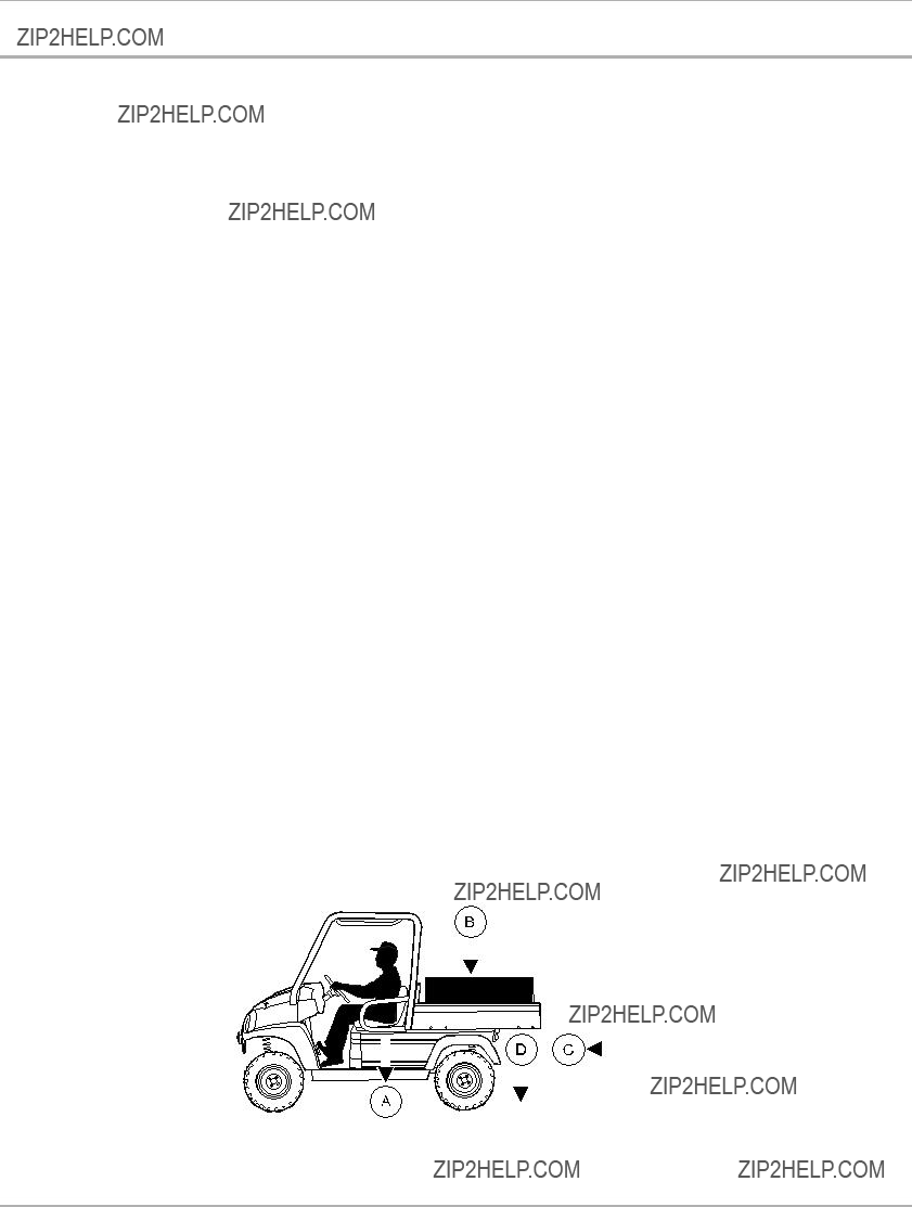
Refer to Figure 12 for the following specifications.
197
Figure 12 Vehicle Load Capacity ???
Page 26 HUV 5420 DX

Towing with the Vehicle
TOWING WITH THE VEHICLE
 WARNING
???Do not tow a vehicle or trailer on public streets or highways.
???Normal vehicle operating speed should be reduced when towing.
???Extreme caution should be used when towing.
???Do not allow riders in the vehicle or trailer being towed.
???Avoid sudden starts, sudden stops, and tight turns when towing.
???Avoid stopping on a hill when towing. If you must stop on a hill, avoid sudden starts, or rolling backwards and stopping suddenly. Failure to heed this warning may cause vehicle to overturn, possibly resulting in severe personal injury.
Towing another Husqvarna vehicle or a trailer can have adverse effects on vehicle handling. Be especially cautious when towing other equipment with a Husqvarna vehicle. See Vehicle Load Capacities on page 26 for vehicle capacity information.
Parking the vehicle with a trailer on a hill should be avoided. If you must park on a hill, apply the brakes and have someone chock the trailer tires. The brakes should be released to allow the chocks to absorb the trailer load. After the trailer tires have been chocked, engage the park brake.
TRANSPORTING ON A TRAILER
 WARNING
???Do not allow riders in the trailer being towed.
???Avoid sudden starts, sudden stops, and tight turns when towing.
???Avoid stopping on a hill when towing. If you must stop on a hill, avoid sudden starts, or rolling backwards and stopping suddenly. Failure to heed this warning could cause the vehicle to overturn, possibly resulting in severe personal injury.
???Reduce normal driving speed when transporting a vehicle on a trailer.
???For use on public roads, the trailer must meet all federal, state, and local requirements such as taillights, brake lights, etc.
???Never tow a Husqvarna vehicle behind a passenger vehicle or truck on a public road unless it is on an approved trailer.
???The vehicle to be transported should be tied securely to the trailer, with the Forward/Reverse handle in the NEUTRAL position, the key switch in the OFF position, and the park brake firmly engaged.
???Because of the added length of the trailer, use caution when making turns.
???Do not transport the vehicle on a trailer with a load in the vehicle cargo bed.
???Remove the vehicle windshield and secure seats before transporting on a trailer.
If the vehicle must be transported over long distances or on public highways, it should be transported on an approved trailer that has an approved load rating of 2000 lb. (908 kg) per vehicle being transported. See following NOTE.
NOTE: A

Storage
STORAGE
See General Warnings on page 8.
 DANGER
???Do not attempt to drain fuel when the engine is hot or while it is running.
???Clean up any spilled fuel before operating the vehicle.
???Store fuel in an approved fuel container only. Store in a
???Keep fuel out of the reach of children.
???Do not siphon fuel from the vehicle.
 WARNING
???Turn the key switch to the OFF position, remove the key, and leave the Forward/Reverse handle in the NEUTRAL position during storage. This is to prevent unintentionally starting the vehicle or a fire hazard.
???Do not attempt to charge frozen batteries or batteries with bulged cases. Discard the battery. Frozen batteries can explode.
 CAUTION
??? Batteries in a low state of charge will freeze at low temperatures.
PREPARING THE VEHICLE FOR EXTENDED STORAGE
1.Unload the vehicle so that the tires are supporting only the weight of the vehicle.
2.Store the vehicle in a cool, dry place. This will minimize battery
3.Make sure the key switch is in the OFF position and the Forward/Reverse handle is in the NEUTRAL position. Chock the wheels.
4.Diesel vehicles: If Biodiesel fuel is used, see Biodiesel Fuel (Diesel Vehicles Only) on page 42. Prepare the fuel tank.
4.1.Fill the fuel tank with fresh fuel.
4.2.Disconnect the fuel vent line from the fuel tank vent nipple (Figure 26).
4.3.Plug the fuel tank vent nipple so that it is air tight. Husqvarna recommends using a
5.Change engine oil. See Engine Oil and Filter Change on page 36.
6.Disconnect battery. See Disconnecting the Battery ??? Diesel Vehicles on page 10.
7.The battery should be clean and free of corrosion. Wash the battery top and terminals with a solution of baking soda and water (1 cup (237 mL) baking soda per 1 gallon (3.8 L) of water). Rinse the solution off the battery. Do not allow this solution to enter the battery. Be sure the terminals are tight. Let the terminals dry and then coat them with Battery Terminal Protector Spray (P/N 603 00
8.Adjust the tires to the recommended tire pressure. See Vehicle Specifications on page 49.
9.Perform semiannual periodic lubrication. See Periodic Lubrication Schedule on page 33.
10. Thoroughly clean the front body, rear body, seats, cargo bed, engine compartment, and underside of vehicle.
Page 28 HUV 5420 DX
Maintenance
11. Do not engage the park brake. Chock the wheels to prevent the vehicle from rolling.
RETURNING THE STORED VEHICLE TO SERVICE
1.Make sure the key switch is in the OFF position and the Forward/Reverse handle is in the NEUTRAL position. Chock the wheels.
2.Restore the fuel system to operation (Figure 26).
2.1.Remove the plug from the fuel tank vent.
2.2.Connect the vent tube to the fuel tank vent.
3.Connect battery. See Connecting the Battery ??? Diesel Vehicles on page 10. Coat terminals with Battery Terminal Protector Spray (P/N 603 00
4.Place the Forward/Reverse handle in the NEUTRAL position. Crank the engine until fuel is pumped into the fuel lines (all vehicles) and the engine starts. Turn the engine off. See following NOTE.
5.Perform the
MAINTENANCE
See General Warnings on page 8.
To ensure
Any vehicle not functioning correctly should not be used until it is properly repaired. This will prevent further damage to the vehicle and help prevent injury to occupants resulting from unsafe conditions.
Contact your local Husqvarna dealer/distributor for repairs and semiannual and annual periodic service.
 WARNING
???Only trained technicians should service or repair the vehicle. Anyone doing even simple repairs or service should have knowledge and experience in electrical and mechanical repair. The appropriate instructions must be used when performing maintenance, service, or accessory installation.
???If any problems are found during scheduled inspection or service, do not operate vehicle until repairs are made. Failure to make necessary repairs could result in fire, property damage, severe personal injury, or death.
???Do not wear loose clothing or jewelry such as rings, watches, chains, etc., when servicing the vehicle.
???Turn key switch to the OFF position, remove the key, place the Forward/Reverse handle in the NEUTRAL position and chock the wheels prior to servicing.
???Moving parts: Do not attempt to service vehicle while engine is running.
???Hot! Do not attempt to service hot engine or exhaust system. Failure to heed this warning could result in severe burns.
???For vehicles with cargo beds, remove all cargo before raising the bed or servicing the vehicle. If the vehicle is equipped with a prop rod, ensure that it is securely engaged while bed is raised. Do not close bed until all persons are clear of cargo bed area. Keep hands clear of all crush areas. Do not drop cargo bed; lower gently and keep entire body clear. Failure to heed this warning could result in severe personal injury or death.
???Do not work on vehicle powertrain or under cargo bed when it is loaded.
WARNING CONTINUED ON NEXT PAGE

Periodic Service Schedule
 WARNING
???To avoid unintentionally starting the vehicle, disconnect battery. See Disconnecting the Battery ??? Diesel Vehicles on page 10.
???If wires are removed or replaced make sure wiring and wire harness are properly routed and secured. Failure to properly route and secure wiring could result in vehicle malfunction, property damage, personal injury, or death.
???Lift only one end of the vehicle at a time. Use a suitable lifting device (chain hoist or hydraulic floor jack) with 1000 lb. (454 kg) minimum lifting capacity. Do not use lifting device to hold vehicle in raised position. Use approved jack stands of proper weight capacity to support the vehicle and chock
the wheels that remain on the floor.
???When servicing the vehicle with part of the vehicle on jack stands, do not operate the engine with the Forward/Reverse handle in either the FORWARD or REVERSE position. The
PERIODIC SERVICE SCHEDULE
See General Warnings on page 8.
 WARNING
???Service, repairs, and adjustments must be made per instructions in the appropriate maintenance and service manual.
NOTE: If the vehicle is constantly subjected to heavy use or severe operating conditions, the preventive maintenance procedures should be performed more often than recommended in the Periodic Service and Lubrication Schedule.
Both the Periodic Service Schedule and the Periodic Lubrication Schedule must be followed to keep vehicle in optimum operating condition.
Page 30 HUV 5420 DX

Periodic Service Schedule
PERIODIC SERVICE SCHEDULE

Periodic Service Schedule
PERIODIC SERVICE SCHEDULE
 WARNING
???If any problems are found during scheduled inspection or service, do not operate vehicle until repairs are made. Failure to make necessary repairs could result in fire, property damage, severe personal injury, or death.
Page 32 HUV 5420 DX

Periodic Lubrication Schedule
PERIODIC LUBRICATION SCHEDULE
PERIODIC LUBRICATION SCHEDULE
Semiannually by owner or
trained technician (or every 50
Rear suspension (2 fittings)Chassis Lube (EP NLGI Grade 2)
hours of operation, whichever comes first)
Figure 13 Lubrication Points ??? Diesel Vehicles

Brake Fluid Reservoir
BRAKE FLUID RESERVOIR
The brake fluid reservoir (1) is located under the hood (Figure 14). Raise the hood to check the brake fluid level.
During the brake fluid level inspection, also inspect the following:
???The presence of brake fluid on the exterior surface of the master cylinder indicates a leak.
???The brake fluid reservoir diaphragm (located in the cap) should not have holes or other damage.
BRAKE FLUID
Brake fluid level should be within
 CAUTION
??? Use only DOT 5 (silicone) brake fluid. Use of any other type brake fluid is not recommended.
Page 34 HUV 5420 DX
Engine Oil
ENGINE OIL
Even though the low oil warning light on the instrument panel should illuminate if the oil level becomes low, the engine oil level should be checked daily. The vehicle should be on a level surface when the oil is checked. Do not overfill the engine with oil.
ENGINE OIL LEVEL CHECK
1.Remove the oil level dipstick from the oil filler tube and wipe oil from the dipstick (Figure 16). See following
CAUTION.
 CAUTION
???Do not remove dipstick while engine is running.
2.Check oil level by fully inserting the dipstick into the tube and immediately removing it.
3.If the oil level is at or below the low level mark on the dipstick gauge, add oil to the engine until the level is between low and full levels (safe level). See following CAUTION.
CAUTION
??? Do not exceed recommended oil capacity. Doing so will decrease engine performance or result in damage to the engine.
1. Full Level 2. Safe Level 3. Low Level
204
Figure 16 Engine Oil Level Check ??? Diesel Vehicles With

Engine Oil
ENGINE OIL AND FILTER CHANGE
Engine oil and oil filter should be changed after the first 50 hours of operation (diesel). After that, they should be changed every 100 hours of operation or annually, whichever comes first.
Engine Oil Draining
1.Turn the key switch to the OFF position and remove the key. Place the Forward/Reverse handle in the NEUTRAL position. Chock the front wheels.
2.Disconnect battery. See Disconnecting the Battery ??? Diesel Vehicles on page 10.
3.Remove the oil filler cap to allow the oil to drain properly.
4.Position a pan designed for oil changes under the drain plug (Figure 17).
5.From the underside of the vehicle, use a socket or wrench to remove the drain plug (1). Turn the plug counterclockwise and drain the engine oil into the pan. See following WARNING.
 WARNING
???Do not attempt to change engine oil when the engine is hot or even warm. Hot engine oil can cause skin burns.
???Wear safety glasses or approved eye protection when servicing the vehicle. Wear rubber gloves when handling oil drain plug, oil filter, and oil drain pan.
6.Clean the oil drain plug threads with solvent to remove oil and oil residue. Make sure that the compression washer remains on the drain plug. Inspect the compression washer and replace if necessary.
7.Use a socket or wrench to replace the oil drain plug (1) (Figure 17). Turn the plug clockwise and tighten to 31
208
Figure 17 Engine Oil Drain Plug and Oil Filter ??? Diesel
Vehicles
Engine Oil Filter Change
1.Drain the engine oil. See Engine Oil Draining on page 36.
2.Place the oil drain pan under the engine oil filter (2) (Figure 17).
3.Remove the engine oil filter. Turn it counterclockwise and drain the residual oil in the filter port and filter into the oil drain pan. See following NOTE.
Page 36 HUV 5420 DX

Engine Oil
NOTE: An oil drip guard (1) can be used to prevent excess oil from dripping onto the engine base plate (Figure 18). Use an empty quart (one liter) container and cut the bottom off at an angle, then slide the open area of the container up and under the oil filter (2) before removal. Position the port of the plastic container so oil will be directed into the oil pan (3). A drip guard can be made by folding a piece of cardboard, thin metal, or plastic under the oil filter, forming a channel to direct the filter port oil into the drain pan.
Dispose of used oil according to the environmental laws and regulations for your area.
4.Use a clean,
5.To help seal the new oil filter to the oil port flange, apply a light coat of white lithium NLGI Number 2 grease (Dow Corning??
NOTE: Use only Husqvarna oil filters designed for your engine.
6.Tighten the oil filter by hand 2/3 turn after gasket contact. Do not use a band wrench or channel lock pliers.
Engine Oil Filling
1.Add engine oil; use a funnel or pour spout to direct the oil into the opening (Figure 20). With filter change, the engine requires 3 qt. (2.8 L) of oil for diesel vehicles. Refer to oil viscosity guidelines for selection of oil grade
(Figure 21). See following CAUTION.
CAUTION
???Do not exceed recommended oil capacity. Doing so will decrease engine performance or result in damage to the engine.
2.Connect battery. See Connecting the Battery ??? Diesel Vehicles on page 10.
3.With the Forward/Reverse handle in the NEUTRAL position, start and run the engine for a few minutes. Observe both the drain plug and the oil filter from under the vehicle and watch for oil leaks. If a leak is detected, check the tightness of the oil filter and drain plug. Tighten, repair, and/or replace components as necessary. See following NOTE.
NOTE: Wait five minutes after turning off the engine before removing the dipstick.
4.Remove the dipstick and check the engine oil as a final step. Replace the dipstick.
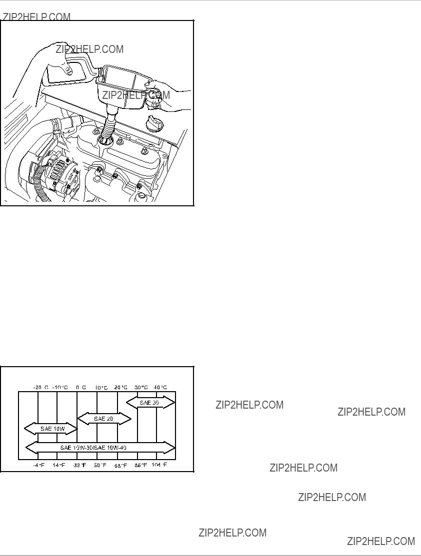
Engine Oil
Figure 20 Add Engine Oil ??? Diesel Vehicles
OIL VISCOSITY
Choose the viscosity according to the temperature as shown in the appropriate oil viscosity chart (Figure 21). See following NOTE.
NOTE: Use engine oil with API classification CF for diesel engines.
Using
Figure 21 Oil Viscosity Chart ??? Diesel Vehicles
Page 38 HUV 5420 DX
Gearcase Lubrication
GEARCASE LUBRICATION
NOTE: Dispose of used oil according to the environmental laws and regulations for your area.
LUBRICATION LEVEL CHECK FOR FRONT DIFFERENTIAL, TRANSMISSION, AND REAR
DIFFERENTIAL
Each gearcase component is equipped with two oil port plugs (1 and 2) (Figure 22, Figure 23, and Figure 24). When the vehicle is on a level surface, use the level indicator hole (upper plug) (1) as a lubricant level indicator. Lubricant level should be even with the bottom of level indicator hole (1).
LUBRICATION CHANGE FOR FRONT DIFFERENTIAL, TRANSMISSION, AND REAR
DIFFERENTIAL
Use the lower plug (2) for drainage (Figure 22, Figure 23, or Figure 24). Remove both plugs to allow the lubricant to drain faster. See preceding NOTE.
Front differential:
Clean and install the drain plug (2) and washer before filling the front differential with new lubricant (Figure 22). Tighten the drain plug to 108
Transmission:
Clean and install the drain plug (2) before filling the transmission with new lubricant (Figure 23). Tighten the drain plug to 96

Engine Coolant ??? Diesel Vehicles
Check the level of lubricant at the level indicator plug (1). Apply Loctite 567 to the threads of the level indicator plug and tighten to 21
Rear differential:
Clean and install the drain plug (2) and washer before filling the rear differential with new lubricant (Figure 24). Tighten the drain plug to 96
(1). See Periodic Lubrication Schedule on page 33. Apply Loctite 567 to the threads of the level indicator plug and tighten to 21
217
Figure 24 Rear Differential Lubrication Level
ENGINE COOLANT ??? DIESEL VEHICLES
ENGINE COOLANT LEVEL CHECK
The coolant reserve tank (2) is located under the hood on the passenger side (Figure 14). Raise the hood to check the coolant level before every operation.
1.Check the coolant level of the reserve tank (2). If the coolant is at or below the LOW mark, add
See following WARNING.
 WARNING
??? Hot! Coolant reserve tank is pressurized. Do not remove cap when engine is hot.
Page 40 HUV 5420 DX

Air Intake System
AIR INTAKE SYSTEM
CAUTION
???Do not drill into the
AIR FILTER REPLACEMENT
The air filter should be inspected periodically and replaced when necessary. Filter changes should not exceed the recommended interval. See Periodic Service Schedule on page 30. More frequent service may be required in extremely dirty operating environments. In the event of a loss of power, sluggish acceleration, or a roughly running engine, service the air filter immediately.
Air Filter Removal
1.Raise the cargo bed, and locate the air filter canister.
2.Release both canister tab locks (Figure 25).
3.Pull the canister cap away from the canister.
4.Remove the air filter cartridge (1). See following NOTE.
NOTE: The air filter cartridge is specifically designed for this engine. It only fits into the canister one way. Use only the Husqvarna part (P/N 603 00
Figure 25 Air Filter Cartridge
Air Filter Installation
1.Push the new air filter cartridge onto the nozzle inside the canister.
2.Place the canister cap, marked TOP, on the top center of the canister.
3.Secure the canister cap with both tab locks.

Fueling Instructions
FUELING INSTRUCTIONS
See General Warnings on page 8.
 DANGER
???Turn the key switch to the OFF position before fueling.
???Do not pour fuel into the fuel tank when the engine is hot or while it is running.
???To avoid electric arc caused by static electricity, the fuel storage/pumping device must be grounded. If the pump is not grounded, the vehicle must be grounded to the pump before and during the fueling operation.
???To avoid the possibility of fire, clean up any spilled fuel before operating the vehicle.
1.Remove the fuel cap and fill the tank with fuel. Diesel vehicles have a green fuel cap. See preceding DANGER and following NOTE.
NOTE: Diesel vehicles: Use only diesel fuel grade no. 2 with a cetane rating of 45 or higher.
2.Replace the fuel cap. Ensure that the cap is tightened securely.
3.Clean any spilled fuel from the cap or around the fuel cap area.
Figure 26 Fuel Tank ??? Diesel Vehicles
BIODIESEL FUEL (DIESEL VEHICLES ONLY)
Biodiesel has unique qualities that should be considered before it is used in the Kubota D722 diesel engine. During cold weather, plugged fuel lines, plugged fuel systems, hard starting, and other unknown failures can result from use of this fuel.
Biodiesel is an excellent medium for microbial growth and contamination. Microbial contamination can cause corrosion of the fuel system and prematurely plugged fuel filters. See following NOTE.
Page 42 HUV 5420 DX

Fueling Instructions
NOTE: Use of biodiesel may result in premature failure of fuel system components. Kubota has documented problems such as plugged fuel filters and deteriorated fuel lines during testing of biodiesel.
Biodiesel can damage painted surfaces. Be sure to remove all spilled fuel immediately to help prevent damage to painted surfaces.
If biodiesel will be used in the Kubota D722 engine, be sure that it meets the following requirements:
???The fuel blend should contain no more than 5% biodiesel by volume.
???The petroleum portion of the fuel blend must meet ASTM standard D975 and the biodiesel portion of the fuel blend must meet ASTM standard D6751.
???For Europe, the fuel blend must meet the EN590 standard. See following CAUTION.
CAUTION
???Never use any fuel that does not meet specifications or fuel in which the contents cannot be identified. Using blends higher than 5% biodiesel content can affect engine life and cause deterioration of hoses, tube lines, injectors, injector pump and seals.
???For more information on these fuel standards, please contact your nearest Kubota dealer.
If biodiesel is used, be sure to apply the following guidelines:
???Ensure the fuel tank is as full as possible at all times to prevent moisture from collecting.
???Ensure that the fuel tank cap is securely tightened to prevent water from entering the fuel tank.
???Drain all water from the fuel filter daily before operating vehicle. See Draining Water from Fuel Filter.
???Check the engine oil level daily before the engine is started. See Engine Oil Level Check on page 35.
???Before vehicle storage, run the engine with conventional diesel fuel for at least 30 minutes to flush the biodiesel from the engine. See Preparing the Vehicle for Extended Storage on page 28. See following NOTE.
NOTE: Biodiesel does not have
Fuel system maintenance, cleaning, and fuel line replacement are required more frequently for engines that are operated with biodiesel.
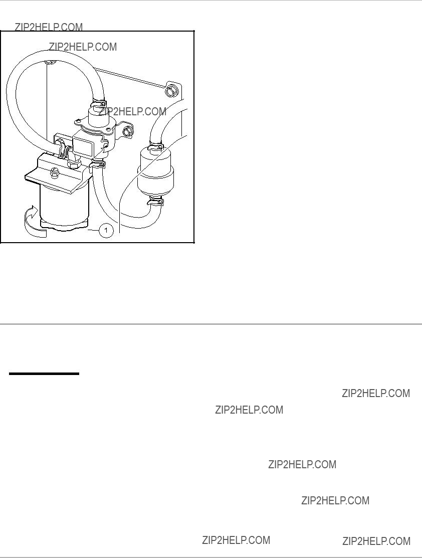
DRAINING WATER FROM FUEL FILTER
Diesel Vehicles Only
Water should be drained from the fuel filter daily. The fuel filter is mounted on a plate by the lower seat support panel (Figure 27).
1.Position a pan under the fuel filter.
2.Lift the
3.Locate the valve (1) on the underside of the filter. Turn the valve clockwise until water begins to stream from the filter.
4.Drain the water until it changes color (to fuel). See following WARNING.
 WARNING
???Clean up spilled fuel. Keep sparks and flames away from the vehicle and service area. Failure to heed this warning could result in an explosion or fire, resulting in severe personal injury or death.
5.Close the valve by rotating it counterclockwise until the valve is firmly sealed.
6.To resupply the filter with fuel, turn the key switch to the ON position for 10 seconds. See following NOTE.
Battery
NOTE: Dispose of water according to the environmental laws and regulations for your area.
221
Figure 27 Fuel Filter
BATTERY
See General Warnings on page 8.
 DANGER
???Battery ??? Explosive gases! Do not smoke. Keep sparks and flames away from the vehicle and service area. Ventilate when charging or operating vehicle in an enclosed area. Wear a full face shield and rubber gloves when working on or near batteries.
???Battery ??? Poison! Contains acid! Causes severe burns. Avoid contact with skin, eyes, or clothing. Antidotes:
???External: Flush with water. Call a physician immediately.
???Internal: Drink large quantities of milk or water followed with milk of magnesia or vegetable oil. Call a physician immediately.
???Eyes: Flush with water for 15 minutes. Call a physician immediately.
???Tools, wires, and metal objects can cause sparks when shorted across a battery.
Page 44 HUV 5420 DX

Battery
 WARNING
???Wear safety glasses or approved eye protection when servicing the vehicle.
???Follow all instructions carefully when working with batteries.
???When jumping from a booster battery make final (negative) connection at engine frame.
???Do not jump start or charge a frozen or damaged battery. Unplug charger before connecting or disconnecting cables to the battery. Never lean over battery while boosting, testing, or charging.
The battery in a Husqvarna vehicle is a
1. Level Indicator 2. Cap 3. Plates
Electrolyte level at least 1/2 inch (13 MM) above plates or to level indicator.
1.Turn the key switch to the OFF position and remove the key. Place the Forward/Reverse handle in the NEUTRAL position. Chock the wheels.
2.Remove
3.Disconnect battery. See Disconnecting the Battery ??? Diesel Vehicles on page 10.
4.Use a
WARNING.
 WARNING
???Wear safety glasses or approved eye protection when servicing the vehicle. Wear a full face shield and rubber gloves when working on or near batteries.
5.Carefully check the electrolyte level and add distilled water if necessary. Do not fill the battery cells above the designated fill line. Replace battery cell caps.
6.Clean both battery terminals with a solution of baking soda and water (1 cup (237 mL) baking soda per 1 gallon (3.8 L) of water). Rinse thoroughly. Do not allow this solution to enter the battery. Be sure terminals are tight. Let the terminals dry and then spray them with Battery Terminal Protector Spray (P/N 603 00
Connecting the Battery ??? Diesel Vehicles on page 10. See following WARNING.

Using A Booster Battery (Jump Starting)
 WARNING
???If battery wire terminals are damaged or corroded, replace or clean them as necessary. Failure to do so may cause them to overheat during operation and could result in a fire, property damage, or personal injury.
Be sure the battery
If battery appears weak, have it charged by a trained technician. The battery should never be left discharged any longer than absolutely necessary (do not leave discharged overnight).
USING A BOOSTER BATTERY (JUMP STARTING)
 WARNING
???Wear safety glasses or approved eye protection when servicing the vehicle. Wear a full face shield and rubber gloves when working on or near batteries.
???When jumping from a booster battery make final connection (negative) at engine frame.
???Do not jump start or charge a frozen or damaged battery. Unplug charger before connecting or disconnecting cables to the battery. Never lean over battery while boosting, testing, or charging.
If it is necessary to use a booster battery to start the engine, BE CAREFUL!
1.Turn the key switch to the OFF position. Place the Forward/Reverse handle in the NEUTRAL position, engage the park brake, and chock the wheels.
2.Ensure the booster battery is
3.Access the engine compartment by raising the cargo bed. See WARNING ???For vehicles with cargo beds...??? in
4.Locate the vehicle battery on the driver???s side of the vehicle under the cargo bed (Figure 30).
5.Connect the end of the first cable (1) to the positive (+) terminal of the booster battery. Connect the other end of the same cable (2) to the positive terminal of the vehicle battery. See DANGER ???Battery ??? Explosive gases!...??? in General Warnings on page 8.
6.Connect the end of the second cable (3) to the negative
7.Sit in the driver???s seat and start the engine.
8.After the engine has started, remove the frame ground
CAUTION
???The alternator can be damaged if the following actions occur:
???Engine is operated with battery cables disconnected.
???Booster cables are connected wrong.
Page 46 HUV 5420 DX

Cleaning the Vehicle
Figure 30 Jump Starting
CLEANING THE VEHICLE
Each vehicle is equipped with
The manufacturer does not recommend any type of pressure washing or steam cleaning. Such a process will expose electrical components to moisture. Moisture entering electrical components can result in water damage and subsequent component failure.
Use
The seats of the vehicle will last longer with proper cleaning. Use a solution of 10% liquid soap and warm water applied with a soft cloth. For imbedded dirt, a soft bristle brush may be used. For heavy soiling, difficult stains, or scratches, blemishes, or other body damage, see the appropriate maintenance and service manual. See following NOTE.
NOTE: Dispose of waste water properly.

Accessories
ACCESSORIES
There is a complete line of accessory equipment available from Husqvarna and our dealers/distributors.
Care should be taken that these accessories are properly installed by trained technicians and that they are used in the manner for which they were designed. See following WARNING and CAUTION.
 WARNING
???Custom cab assemblies, canopy tops, weatherproof enclosures, and windshields will not protect occupants from flying objects.
???If the vehicle is equipped with an
CAUTION
???Do not drill into the
ELECTRIC WINCH ACCESSORY
If your vehicle is equipped with an electric winch, read and follow all manufacturer safety warnings and instructions in the winch operator manual, as well as the following WARNING and CAUTION statements. Make sure a winch warning decal is affixed to the vehicle on the seat support panel next to the receptacle for the remote operation switch.
The winch kit available from Husqvarna includes a remote operation switch, which enables the operator to move away from the vehicle and cable. See following WARNING and CAUTION.
 WARNING
???Before beginning a winch operation:
???Turn key switch to the OFF position, put Forward/Reverse handle in the NEUTRAL position, and engage the park brake.
???Do not use winch while persons are seated on the vehicle.
???Stand to the side and away from the vehicle to operate winch.
CAUTION
???Use of the winch for an extended period of time could discharge the battery. Keep winch operations as short as possible, and drive the vehicle for several minutes after the winch operation to recharge the battery.
Page 48 HUV 5420 DX

Vehicle Specifications
Page 50 HUV 5420 DX
BC55284
Publication Part Number 103472545
Edition Code 0409F0110E
This manual is valid for vehicles built during the 2009 model year.
It is also valid for vehicles with build codes between 54699 and the one indicated at the top of this page.
103472545