For Your Records and Warranty

Assistance

Model Name: ______________________

Catalog/Model No.: _________________

Serial No.: ________________________

Date Purchased: ____________________

Where Purchased: _ _________________

For reference also attach your receipt or a copy of your receipt to the manual.

TYPE E Models

43113-01 ??? 04/13/07

Welcome


Your new Hunter?? ceiling fan is an addition to your home or office that will provide comfort and performance for many years. This installation and operation manual gives you complete instructions for installing and operating your fan.

We are proud of our work. We appreciate the opportunity to supply you with the best ceiling fan available anywhere in the world.

Before installing your fan, for your records and warranty assistance, record information from the carton and Hunter nameplate label (located on the top of the fan motor housing).

Cautions and Warnings

???READ THIS ENTIRE MANUAL CAREFULLY BEFORE

BEGINNING INSTALLATION. SAVE THESE INSTRUCTIONS.

???Use only Hunter replacement parts.

???To reduce the risk of personal injury, attach the fan directly to the support structure of the building according to these instructions, and use only the hardware supplied.

???To avoid possible electrical shock, before installing your fan, disconnect the power by turning off the circuit breakers to the outlet box and associated wall switch location. If you cannot lock the circuit breakers in the off position, securely fasten a prominent warning device, such as a tag, to the service panel.

???All wiring must be in accordance with national and local electrical codes and ANSI/NFPA 70. If you are unfamiliar with wiring, use a qualified electrician.

???To reduce the risk of personal injury, do not bend the blade attachment system when installing, balancing, or cleaning the fan. Never insert foreign objects between rotating fan blades.

???To reduce the risk of fire, electrical shock, or motor damage, do not use a solid-state speed control with this fan. Use only Hunter speed controls.

Standard Mounting hangs from the

ceiling by a downrod (included).

Low Profile Mounting fits close to the

ceiling, recommended for ceilings less than 9 feet high

1 ??? Getting Ready

Installing Multiple Fans?

If you are installing more than one fan, keep the fan blades and blade irons (if applicable) in sets, as they were shipped.

To install a ceiling fan, be sure you can do the following:

???Locate the ceiling joist or other suitable support in ceiling.

???Drill holes for and install wood screws.

???Identify and connect electrical wires.

???Lift 40 pounds.

If you need help installing the fan, your Hunter fan dealer can direct you to a licensed installer or electrician.

Gathering the Tools

You will need the following tools for installing the fan:

???Electric drill with 9/64??? bit

???Standard screwdriver (magnetic tip recommended)

???Phillips-head screwdriver (magnetic tip recommended)

???Wrench or pliers

???Ladder (height dependent upon installation site)

Checking Your Fan Parts

Carefully unpack your fan to avoid damage to the fan parts. Refer to the included Parts Guide. Check for any shipping damage to the motor or fan blades. If any parts are missing or damaged, contact your Hunter dealer or call Hunter Technical Support Department at 888-830-1326.

Preparing the Fan Site

Before you begin installing the fan, follow all the instructions in the pullout sheet called ???Preparing the Fan Site.??? Proper ceiling fan location and attachment to the building structure are essential for safety, reliable operation, maximum efficiency, and energy savings.

2 ??? Installing the Ceiling Plate

CAUTION: To avoid possible electrical shock, before installing your fan, disconnect the power by turning off the circuit breakers to the outlet box and associated wall switch location. If you cannot lock the circuit breakers in the off position, securely fasten a prominent warning device, such as a tag, to the service panel.

2-1. Drill one hole on each side of the supply mains using the holes in the u-bracket as a guide. The pilot holes should be 9/64??? in diameter.

2-2. Place the bushing pin assembly into the u-bracket.

2-3. Screw the u-bracket screws through the u-bracket and into the pilot holes.

9/64???

Step 2-1


Step 2-2

Step 2-3

3 ??? Assembling and Hanging the Fan

Rubber

Gasket

Upper

DecorativeCanopy

Sleeve

Lower

Canopy

Adaptor

Rubber

Gasket


Step 3-1

Step 3-2 - 3-3

WARNING: Fan may fall if not assembled as directed in these installation instructions.

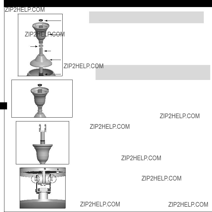
Standard Mounting - 9??? ceilings or higher:

???Threading the wires through the adapter, screw the adapter onto the shaft on the top of the fan and securely tighten the upper setscrew with the included allen wrench.

???Loosen the lower setscrew in the adapter. Threading the wires through the 7??? pipe, screw the pipe into the adapter on top of the fan and securely tighten the upper setscrew.

CAUTION: The adapter has a special coating on the threads. Do not remove this coating; the coating prevents the downrod from unscrewing. Once assembled, do not remove the downrod.

???Slide the lower canopy onto the pipe with the large opening facing the fan.

???Slide the metal gasket and decorative sleeve onto the pipe (in that order). Orient the gaskets so that the sleeve will overlap the lip of each gasket.

???Slide the upper canopy onto the pipe with the large opening facing away from the fan. Then slide the rubber gasket onto the pipe, oriented so that the lip slides into the sleeve. Continue to step 3-1.

Low Profile Mounting - 8??? - 9??? ceilings:

Note: For Low Profile Mounting, Adapter is not used.

???Threading the wires through the 2.75??? pipe, screw the pipe into the top of the fan and securely tighten the setscrew.

???Slide the lower canopy onto the pipe with the large opening facing the ceiling, the upper canopy is not used for low profile mounting.

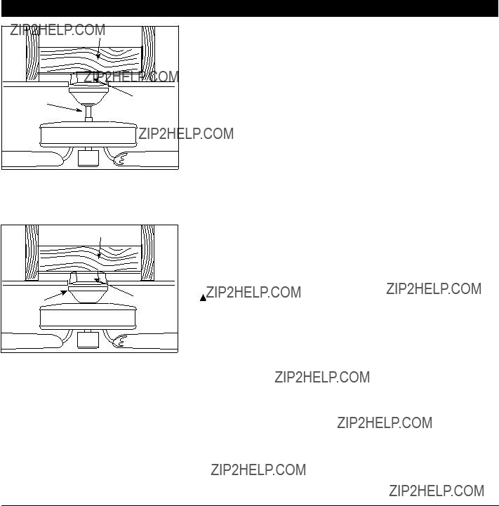
3-1. Screw the hanger bracket onto the top of the pipe at least three full turns. Securely tighten the setscrew on the hanger bracket.

3-2. Center the pin in the rubber bushing.

3-3. Holding the fan by both the motor housing and the pipe, lift the fan assembly and hook both sides of the hanger bracket onto the bushing pin assembly.

4 ??? Wiring the Fanfsdfsdf

All wiring must be in accordance with national and local electrical codes and ANSI/NFPA 70. If you are unfamiliar with wiring, use a qualified electrician.

Wall switches are not included. Select an acceptable general-use switch in accordance with national and local electrical codes.

4-1. Before attempting installation, make sure the power is still off.

4-2. To connect the wires, hold the bare metal leads together and place a wire nut over them, then twist clockwise until tight. For all these connections use the wire nuts provided.

4-3. Connect the bare or green ground wire (grounded) from the ceiling to the green ground wire (grounded) from the ceiling plate and the green ground wire from the fan.

4-4. Connect the white wire (ungrounded) from the ceiling to the white wire (ungrounded) from the fan.

4-5. Connect the remaining wires as follows:

Dual Switch Wiring:

???The black wire (ungrounded) from the ceiling to the black wire (ungrounded) from the fan

Wire Nut


Single Switch Wiring:

??? The black wire (ungrounded) from the ceiling to the black (ungrounded) and the black/white wire (ungrounded) from the fan

CAUTION: Be sure no bare wire or wire strands are visible after making connections.

4-6. Turn the splices upward and push them carefully back through the ceiling plate into the outlet box.

4-7. Spread the wires apart, with the grounded wires on one side of the outlet box and the ungrounded wires on the other side of the outlet box.

5 ??? Installing the Canopy

Step 5-1

Step 5-2


Step 5-3

WARNING: Fan may fall if not assembled as directed in these installation instructions.

Standard Mounting

Note: The lower canopy, along with the sleeve & gaskets, must be raised first so that the upper canopy can secure to the sleeve.

5-1. Raise the lower canopy, along with the decorative sleeve and two gaskets, so that the lower edge is even with the upper edge of the motor housing. Securely install the setscrews in the lower canopy and metal gasket.

5-2. Raise the upper canopy, leaving 1-2 mm of space between the rim of the canopy and the ceiling, and securely install the setscrew.

Low Profile Mounting

5-3. Raise the canopy, leaving 1-2 mm of space between the rim of the canopy and the ceiling, and securely install the setscrew.

6 ??? Assembling the Blades

Hunter fans use several styles of fan blade irons (brackets that hold the blade to the fan).

6-1. Your fan may include blade grommets. If your fan has grommets, insert them by hand into the holes on the blades.

6-2. Attach each blade to a blade iron using three blade assembly screws (the carved side should face downward). If you used grommets, the blades may appear slightly loose after screws are tightened. This is normal.

6-3. For each blade, insert one blade mounting screw through the blade iron, and attach lightly to the fan. Insert the second blade mounting screw, then securely tighten both mounting screws.

6-4. Attach the fandangles (included) to the fan pull chains using the plastic breakaway connector. (You may find the plastic breakaway connector on the end of the extra chain.)

Step 6-1 (Detail)

Grommet

7 ??? Accessory Light Option

Step 7-1

10

Step 7-2

Step 7-6

This fan was designed to accept any Hunter listed light kit. If you decide to install a light kit, follow these steps to install the included light kit adapter then follow the instructions supplied with the light kit.

7-1. Remove the two screws from the reversing switch.

7-2. Unscrew the nut on the switch housing cover. You may need to use pliers to loosen the nut.

7-3. Remove the two screws in the switch housing cover and remove the cover.

7-4. Install the reversing switch into the light kit adapter with the two screws removed in step 7-1.

7-5. Thread the fan pull chain through the side of the light kit adapter and secure with the nut removed in step 7-2.

7-6. Attach the light kit adapter to the upper switch housing with the two screws removed in step 7-3.

7-7. Follow the instructions supplied with the accessory light kit to complete installation of the light kit.

8 ??? Operating and Cleaning Your Ceiling Fan

8-1. Turn on electrical power to the fan.

8-2. The fan pull chain controls power to the fan. The pull chain has four settings in sequence: High, Medium, Low and Off.

??? Pull the chain slowly to change settings.

??? Release slowly to prevent the chain from recoiling into the blades.

???The chain uses a breakaway connector that separates if the chain is jerked. If this happens, simply reinsert the chain into the connector.

To Change Airflow Direction

Turn the fan off and let it come to a complete stop. Slide the reversing switch on the fan to the opposite position. Restart fan.

Reversing

Switch

9 ??? Troubleshooting