365i Combo Operations Manual
365i Combo Operations Manual

Thank You!
Thank you for choosing Humminbird??, America???s #1 name in fishfinders. Humminbird?? has built its reputation by designing and manufacturing
To contact our Customer Resource Center, call
WARNING! This device should not be used as a navigational aid to prevent collision, grounding, boat damage, or personal injury. When the boat is moving, water depth may change too quickly to allow time for you to react. Always operate the boat at very slow speeds if you suspect shallow water or submerged objects.
WARNING! Disassembly and repair of this electronic unit should only be performed by authorized service personnel. Any modification of the serial number or attempt to repairthe original equipment or accessories by unauthorized individualswill void the warranty.
WARNING! This product contains chemicals known to the State of California to cause cancer and/or reproductive harm.
WARNING! Do not travelat high speed with the unit coverinstalled.Remove the unit cover before traveling at speeds above 20 mph.
NOTE: Some features discussed in this manual require a separate purchase, and some featuresare only available on international models. Every efforthas been made to clearly identify those features. Please read the manual carefully in order to understand the full capabilities of your model.
ENVIRONMENTAL COMPLIANCE STATEMENT: It is the intentionof Humminbird??to be a responsible corporate citizen, operating in compliance with known and applicable environmentalregulations, and a good neighbor in the communities where we make or sell our products.

WEEE DIRECTIVE: EU Directive2002/96/EC ???Wasteof Electricaland ElectronicEquipment Directive (WEEE)??? impacts most distributors, sellers, and manufacturers of consumer electronics in the European Union. The WEEE Directive requires the producer of consumer electronics to take responsibility for the management of waste from their products to achieve environmentally responsible disposal during the product life cycle.
WEEE compliance may not be required in your locationfor electrical & electronicequipment (EEE), nor may it be required for EEE designed and intended as fixed or temporary installation in transportation vehicles such as automobiles, aircraft, and boats. In some European Union member states, these vehicles are consideredoutside of the scope of the Directive, and EEE for those applications can be considered excluded from the WEEE Directive requirement.
This symbol (WEEE wheelie bin) on product indicates the product must not be disposed of with other household refuse. It must be disposed of and collectedfor recycling and recovery of waste EEE. Humminbird?? will mark all EEE products in accordance with the WEEE Directive. It is our goal to comply in the collection, treatment, recovery, and environmentally sound disposalof those products;however, these requirements do vary within European Union member states. For more information about where you should dispose of your waste equipment for recyclingand recovery and/or your European Union member state requirements, please contact your dealer or distributorfrom
which your product was purchased.
ROHS STATEMENT: Product designed and intended as a fixed installation or part of a system in a vessel may be considered beyond the scope of Directive 2002/95/EC of the European Parliament and of the Council of 27 January 2003 on the restrictionof the use of certain hazardous substances in electrical and electronicequipment.
ATTENTION INTERNATIONAL CUSTOMERS: Products sold in the U.S. are not intended for use in the international market. Humminbird?? internationalunits provide international features and are designed to meet country and regional regulations. Languages, maps, time zones, units of measurement, and warranty are examples of features that are customized for Humminbird?? international units purchased through our authorized international distributors.
To obtain a list of authorized international distributors, please visit our web site at www.humminbird.com or contact our Customer ResourceCenter at (334)
Navionics?? Gold, HotMaps???, and HotMaps??? Premium are registered trademarks of Navionics??. 300 Series???, DualBeam PLUS???, Fish ID+???, Humminbird??, RTS???, RTS Window???, Structure ID??, SwitchFire???, WhiteLine???, UniMap???, and
?? 2009 Humminbird??, Eufaula AL, USA. All rights reserved.

i
ii
iii

iv
v

vi

NOTE: Entries in this Table of Contents which list (International Only) are only available on products sold outside of the U.S. by our authorized international distributors. To obtain a list of authorized international distributors, please visit our web site at www.humminbird.com or contact our Customer Resource Center at
(334)
NOTE: Entries in this Table of Contents which list (with Temp/Speed only) require the purchase of separate accessories . You can visit our web site at www.humminbird.com to order these accessories online or contact our Customer Resource Center at
NOTE: Some features discussed in this manual require a separate purchase, and some features are only available on international models. Every effort has been made to clearly identify those features. Please read the manual carefullyin order to understand the full capabilities of your model.
vii
Power On the Unit
Follow the instructions below to power on your Humminbird?? control head.
365i Combo Title Screen
1.Press the  POWER/LIGHT key.
2.When the Title screen is displayed, press the MENU key to access the
3.Use the
NOTE: See
???If a functioning transducer is connected, Normal operation will be selected automatically at power up, and your Fishfinder can be used on the water.
???If a transducer is not connected and you wait too long to select a
???In Simulator you can learn how to use your control head and save settings in advance for later use.

How Sonar Works
Sonar technology is based on sound waves. The 300 Series??? Fishfinder uses sonar to locate and define structure, bottom contour and composition, as well as depth directly below the transducer.
Your 300 Series??? Fishfinder sends a sound wave signal and determines distance by measuring the time between the transmission of the sound wave and when the sound wave is reflected off of an object; it then uses the reflected signal to interpret location, size, and composition of an object.
Sonar is very fast. A sound wave can travel from the surface to a depth of 240 ft (70 m) and back again in less than 1/4 of a second. It is unlikely that your boat can ???outrun??? this sonar signal.
SONAR is an acronym for SOund and NAvigation Ranging. Sonar uses precision sound pulses or ???pings??? which are emitted into the water in a
The sound pulses ???echo??? back from objects in the water such as the bottom, fish, and other submerged objects. The returned echoes are displayed on the LCD screen. Each time a new echo is received, the old echoes are moved across the LCD, creating a scrolling effect.

When all the echoes are viewed side by side, an easy to interpret ???graph??? of the bottom, fish, and structure appears.
The sound pulses are transmitted at various frequencies depending on the application. Very high frequencies (455 kHz) are used for greatest definition but the operating depth is limited. High frequencies (200 kHz) are commonly used on consumer sonar and provide a good balance between depth performance and resolution. Low frequencies (83 kHz) are typically used to achieve greater depth capability.
The power output is the amount of energy generated by the sonar transmitter. It is commonly measured using two methods:
???Root Mean Square (RMS) measures power output over the entire transmit cycle.
???Peak to Peak measures power output at the highest points.
The benefits of increased power output are the ability to detect smaller targets at greater distances, ability to overcome noise, better high speed performance and enhanced depth capability.

DualBeam PLUS??? Sonar
Your 300 Series??? Fishing System uses a 200/83 kHz DualBeam PLUS??? sonar system with a wide (60??) area of coverage. DualBeam PLUS??? sonar has a narrowly focused 20?? center beam, surrounded by a second beam of 60??, expanding your coverage to an area equal to your depth. In 20 feet of water, the wider beam covers an area 20 feet wide. DualBeam PLUS??? sonar returns can be blended together, viewed separately, or compared

How GPS Works
Your 300 Series??? Fishfinder also supports GPS (Global Positioning System) and chartplotting. It uses GPS and sonar to determine your position, display it on a grid, and provide detailed underwater information.
GPS uses a constellation of satellites that continually send radio signals to the earth. The GPS receiver on your boat receives signals from satellites that are visible to it. Based on time differences between each received signal, the GPS receiver determines its distance to each satellite. With distances known, the GPS receiver mathematically triangulates its own position. With once per second updates, the GPS receiver then calculates its velocity and bearing.
GPS was originally intended for military use; however, civilians may also take advantage of its highly accurate position capabilities, typically within +/- 4.5 meters, depending on conditions. This means that 95% of the time, the GPS receiver will read a location within 4.5 meters of your actual position. Your GPS Receiver also uses information from WAAS (the Wide Area Augmentation System), EGNOS (the European Geostationary Navigation Overlay Service), and MSAS (the MTSAT Satellite Augmentation System) satellites if they are available in your area.
The following GPS functionality is currently supported by the 300 Series??? Fishfinder when it is connected to the included GPS receiver:
???View current position
???View current track (breadcrumb trail)
???View precision speed and heading from your GPS receiver
???Save tracks, waypoints, and routes
???Travel a route and navigate from one waypoint to the next.
See Chart View and Introduction to Navigation: Add Maps to Your Fishfinder for more information.
What???s on the Sonar Display
The 300 Series??? Fishfinder can display a variety of useful information about
Depth - Waterdepth; can be set to alarm when the water becomestoo shallow.
Speed - If a Temp/Speed accessory or GPS Receiver is attached, the Fishfinder can display the speed of the boat and can keep a Triplog of nautical or statutemiles traveled.
Temperature - Water surfacetemperature.
Timer - Elapsed time with Temp/Speed
Accessory or GPS Receiver.
Distance - Distance traveled with Temp/Speed
Accessory or GPS Receiver.
Average Speed - Average speed reading with
Temp/Speed Accessory or GPS Receiver.
Second Sonar Return - When the sonar signal bouncesbetweenthebottomand thesurface ofthe water and backagain. Use the appearance of the second returnto determine bottomhardness. Hard bottomswillshowa strongsecondreturn,whilesoft bottomswillshowa veryweakone ornoneat all.
Cursor Dialog Box - Indicates cursor depth on the display and the depth of the bottom directly below the cursor. The Latitude and Longitude of the cursor position, the distance to travel to the cursor position, and the bearing to the cursor position are shown with a GPS receiver. A waypoint can be marked at the cursor position for later retrieval and use with a GPS receiver.
NOTE: Entries in this view that list (with Temp/Speed or GPS Receiver) are available if either the information from the GPS receiver will be displayed on the view.

the area under your boat, including the following items:
Bait Ball
Hollow Fish Symbol (83kHz, Wide Beam)
Fish - The Fishfinder displays fish as arches and/or fish icons, and can be set to alarm when a fish of a certain size is detected. When a target is detected, a Fish ID+??? symbol appears on the display with the depth displayed above it. The size of the symbol indicates the intensity of the sonar return. The unit will clearly show schools of Bait Fish as "clouds" of different shapes and sizes, depending on the number of fish and boat speed.
Shaded Fish Symbol (200 kHz, NarrowBeam)
Thermoclines - Layers of water with different temperatures that appear at different depths and different times of the year. A thermocline typically appears as a continuous band of gray levels moving across the display at the same depth.
Cursor - Available in Freeze Frame and can be positioned in the Sonar View to provide depth of a sonar return and bottom depth below the cursor.
RTS (Real Time Sonar) Window???
Structure - Wherefish may be hiding.
device is connected to the 300 Series??? Fishfinder. If both devices are connected, then only
Understanding the Sonar Display
It is im portant to understand the significance of the display. The d isplay d oes n ot sh ow a literal
The returned sonar echoes ar e displa yed on the screen. As a new ec ho is received, the historical data scrolls left across the view.
Real Time Sonar (RTS???) Window
A Real Time Sonar (RTS???) Window appears on the right side of the display in the Sonar View only. The RTS Window??? updates at the fastest rate possible for depth conditions and shows only the returns from the bottom, structure, and fish that are within the transducer beam . The RTS Wind ow??? plots the depth and intensity of a sonar return (see Sonar Menu Tab: RTS Window???).
The Narrow RTS Window??? indicates the sonar intensity through the use of grayscale. The g rayscale used ma tches the Bottom View grays cale setting (Inverse, StructureID??, WhiteLine???, Bo ttom Blac k). The depth of the sonar return is indicated by t he ver tical placement of the return on the display depth scale.
The Wide R TS W indow??? indicates t he so nar i ntensity through the u se of a ba r graph. The length of the plotted r eturn indicates whether the return is weakor strong. The depth of the sonar return is in dicated by th e vertical p lacement of th e return o n the d isplay d epth

SwitchFire???
SwitchFire??? controls how the sonar returns are displayed in the Sonar Views. SwitchFire??? settings are available in the Sonar Menu Tab.
To see the maximum sonar information available within the transducer beam so more fish arches and better jig tracking are shown, choose Max Mode.
To see less clutter and more fish size accuracy interpreted from the transducer beam, cho ose Clear Mode. See Sonar Menu Tab: Switch Fire??? for more information.
Freeze Frame and Active Cursor
Freeze Frame & Active Cursor - Press any arrow on the
The RTS Window??? continues to update in Freeze Frame. To return to a scrolling display and exit Freeze Frame,press the EXIT key. Freeze Frame is available in the
Sonar, Split Sonar, and Sonar Zoom Views.
Instant Image Update
Instant Image Update - You can change a variety of sonar menu settings (such as Sensitivity or Upper Range), and the adjustments will be shown instantly on the screen.
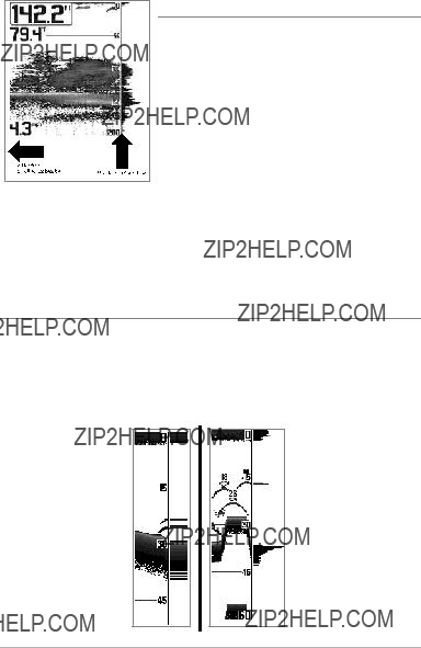
Bottom Presentation
As the boat moves, the unit charts the changes in depth on the display to create a profile of the Bottom Contour. The type of b ottom can be d etermined from the return charted on the display. A Hard Bottom such as compacted sediment or flat rock appears as a thinner line across the display. A Soft Bottom such as mud or sand appears as a thicker line across the display. Rocky Bottoms have a broken, random appearance.
Bottom Contour Profile with RTS Window???
Hard Bottom
Soft Bottom
Rocky Bottom
The sonar returns from the bott om, structure, and fish can be represented as
Inverse, Structure ID?? , WhiteLin e???, o r Black (Bottom Black). See Sonar
Inverse is a method where weak r eturns are shown with dark pixels and strong returns with lighter pixels. This has the benefit of e nsuring that weak signals will be clea rly visible on the display.
Structure ID?? represents weak returns as light pixels and strong r eturns as d ark p ixels. This ha s the benefit of ensuring that strong returns will be clearly visible on the display.
WhiteLine??? highlights the strongest sonar returns in white resulting in a dis tinctive outline. This has the benefit of clearly defining the bottom on the display.
Black (Bottom Black) displays all pixels below the bottom contour as black, regardless of signal strength. This has the benefit of pro viding a high c ontrast between the bottom and other sonar returns on the display.

Views
The sonar and navigation information from your Fishfinder are displayed on the screen in a variety of
When you first power up the control head, Sonar View will be the default view. You can display and hide any view to suit your fishing preferences.
NOTE: When you change any menu settings that affect the sonar,the view will update immediately. Youdon't have to exit the menu to apply the change to the screen.
(see
Circular Flasher View
Snapshot and Recording View
Self Test View
(see
Accessory Test View
(see
Details about each view are available on the following pages.

To customize your view rotation:
You can choose which views are hidden or visible in your view rotation.
1.Press the M ENU key t wice t o acc ess th e tab bed Main Menu, then press the RIGHT Cursor key until the Views tab is selected.
2.Press the UP or DOWN Cursor keys to select a View.
3.Press the LEFT or RIGHT Cursor keys to change the status of the view from Hidden to Visible or vice versa.
To change the Digital Readouts:
Each view displays digital readout information (such as sp eed or time), which varies with the view selected, the accessory attached, and whether or not you are navigating. The digital readouts on the Sonar View can be customized. See
Setup Menu Tab: Select Readouts for more information.
1.Press the M ENU key t wice t o acc ess th e tab bed Main Menu, then press the RIGHT Cursor key until the Setup tab is selected.
2.Press the DOWN key to highlight Select Readouts, and press the RIGHT Cursor key to access the Select Readouts submenu.
NOTE: If the Select Readouts option does not appear under theSetup tab, change the User Mode to Advanced.
3.Press the UP or DOWN Cursor keys to select a Readout position, then press the RIGHT or LEFT Cursor keys to choose what will be displayed in that position. To hide the data window, select Off. (Course, Navigation, Off, Position, Speed, Temperature, Time+Date, Triplog, Voltage, Time).

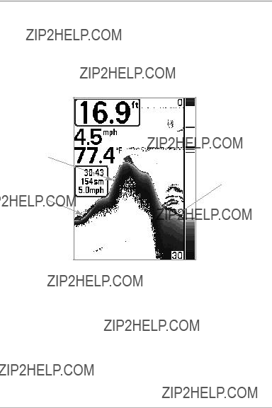
Sonar View
Sonar View presents a historical log of sonar returns. The most recent sonar returns a re chart ed on t he right side of the display. As ne w informa tion is received, the historical information scrolls left across the display.
???Upper and Lower Depth Range numbers indicate the distance from the surface of the water to a depth range sufficient to show the bottom.
???Depth is automatically selected to keep the bottom visible on the display, although you can adjust it manually as well (see Sonar
???Digital Readouts shown on the display will change based on the Select Readouts settings or the
Setup Menu Tab: Select Readouts).
???Freeze Frame: Use the
Sonar View
Speed 
Temperature
Cursor
Triplog
 RTS Window???
Sonar History
Window
Cursor
Dialog Box
NOTE: If the Depth number is flashing, it means that the unit is having trouble locating the bottom. This usually happens if the water is too deep, the transducer isout of the water, theboat is moving too fast, or for any other reason that the unit can???t accurately receive continuous data.

Sonar Zoom View
Sonar Zoom View provides a magnified view of the bottom and structure. The Sonar Zoom View makes it easier to see sep arate so nar return s that would usually be displayed close together, such as t hose caused by fish su spended close to the bottom or within structure.
???The Zoom Level, or magnification, is displayed in the lower left corner of the display. Press the + or - ZOOM keys to increase or decrease the zoom level.
???The Zoomed View is displayed on the le ft side of th e screen. As the depth changes, the zoomed view updates automatically.
???The Full Range View is displayed on the right sid e of the sc reen. The Full Range View includes the Zoom Preview Box, wh ich shows where the zoomed view is in relation to the full range view.
???The Upper and Lower Depth Range numbers indicate the high and low range of the water which is being viewed.
???Digital Readouts cannot be customized; therefore, information such as water temperature and voltage are unavailable in the Sonar Zoom View.
Sonar Zoom View
 Upper Depth Range,
Full Range View
Depth
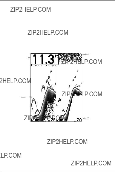
200/83 kHz Split Sonar View
Split Sonar View displays sonar returns from the 83 kHz wide beam on the left side of the screen and sonar returns fromthe 200 kHz narrow beam on the right side of the screen. You can use the Sp lit Sonar View to m ake side by sid e comparisons between the sonar returns from both beams.
??? Depth is displayed in the upper left hand corner.
??? The Digital R eadouts in the Split Sonar View cannot be customized; therefore, inf ormation such as wa ter temperatu re and voltage a re unavailable in the Split Sonar View.
200 kHz Sonar
 History Window
83 kHz Sonar History Window
Lower Depth
Range

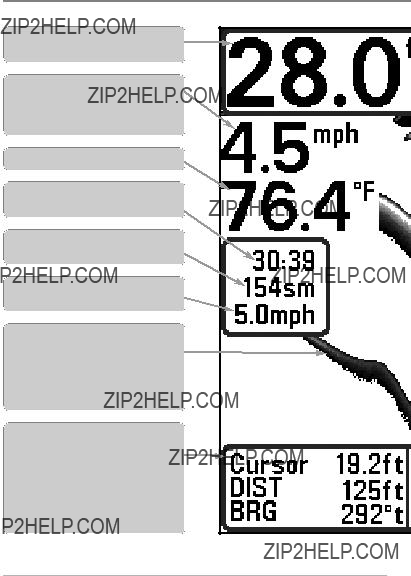
Big Digits View
Big Digits View provides digital data in a large,
???Digital Readouts: Depth is always displayed. Readouts for temperature, speed, a nd Triplog i nformation a re d isplayed automatically if the appropriate accessory is connected to the Fishfinder.
NOTE: The digital readouts in the Big Digits View cannot be customized.
???The Triplog shows distance traveled, average speed, and time elapsed since the Triplog was last reset.
Big Digits View
Depth
Temperature 
Speed
Timer shows the
time elapsed since Triplog was last reset
Distance is the distance traveled since the Triplog was last reset
Voltage displays the battery voltage
Average Speed shows the speed since the Triplog was last reset

Circular Flasher View
Circular Flasher View displays Real Time Sonar (RTS???) data in the traditional flasher format.
???Depth and temperature are always displayed.
???The Digital Readouts in Circular Flasher View cannot be customized.

Snapshot and Recording View
The Snapshot and Reco rding View displays t he screen snapsh ots a nd recordings that are saved on the
???Activate S creen Snapsh ot: Select Sc reen Sna pshot from the Setup Menu Tab, and select On. Also, install an
???Scroll and View: Use the UP and DOWN Cursor keys to scroll th rough
the saved S creen S napshots a nd Re cordings. The active file i s highlighted with arrows. Press the RIGHT Cursor key to view the file.
???Snapshot and R ecording
Snapshot and Recording View
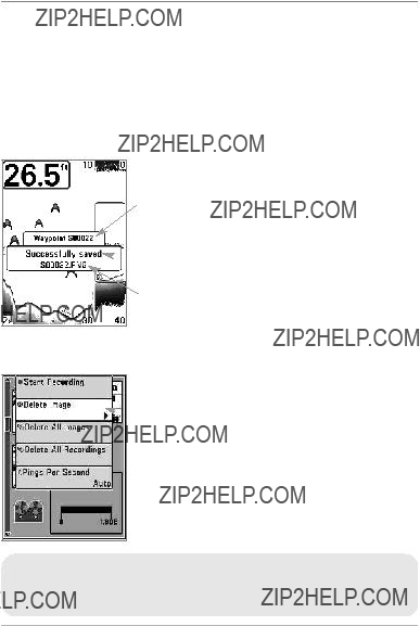
Screen Snapshots
Screen Snapshots are saved pictur es of the v iew on the screen. The screen snapshot will include the menus, dialog boxes, warnings, and messages that were active when the screen snapshot was taken. Saved Screen Snapshots can be viewed from the Snapshot and Recording View or Chart View.
The Screen Snapshot feature is available when an
Waypoint saved at Cursor Location
 Screen Snapshot
Confirmation
File Name
Delete a Screen Snapshot
 From Snapshot and Recording View, select Delete Image from the
1.Activate Scre en Sn apshot and install an MMC/SD card.
2.From any view or cursor location you w ant to capture, p ress the MARK key. The screen will pause while the image is saved.
A waypoint will also be created at the boat or active cursor loc ation. The screen sn apshot sh ares the same file name (.PNG).
Delete a Screen Snapshot:
1. From the Snapshot and Recording View, p ress th e UP or DOW N Cursor keys to scroll through the saved fil es a nd hi ghlight a snapshot file.
2.Press t he M enu k ey o nce, and select Delete I mage fr om t he
3.Press the RIGHT Cursor key.
NOTE: Navigation is not affected by the Screen Snapshot feature. Also, if Screen Snapshot is enabled, but a GPS receiver is not connected, pressing the MARK ke y will capture the screen image but an error will display that says a GPS position fixis requiredto create a waypoint.
View a Screen Snapshot
 Snapshot File
Name
 Time + Date of
Snapshot
Waypoint
Position
Highlighted File
 MMC/SD card storage available
View a saved Screen Snapshot from Snapshot and Recording View:
1.From the Snapshot and Recording View, p ress t he UP or DOWN Cursor keys to scroll through the saved files a nd highlight a snapshot file.
2.Press the RIGHT Cursor key.
View a saved Screen Snapshot from Chart View:
View Screen Snapshot in
Chart View
Screen Snapshot
Icon and
Waypoint Name
Thumbnail Preview
(press the INFO key to view at full size)
Notes about Screen Snapshots:
1.In Ch art View, use the 4
When t he c ursor sna ps onto the Screen Sn apshot Icon, a th umbnail preview o f t he Screen Sn apshot w ill be displayed on the screen.
2.Press the INFO ke y, an d s elect View Snapshot.
3.Press the EXIT key to retu rn to Chart View.
???A border around the full screen indicates that the view is a savedscreen snapshot and not a ???live??? view.
???If you press the INFO key, and the snapshot file connected to the ic on is not saved on the installed MMC/SD card, the chart information box will display instead of the screen snapshot.
???Use an
This data file is req uired for v iewing th e screen sna pshots from your control head, so don???t delete these files.
Recording and Playback
The Recording feature records active sonar information. When the recording is played back, the v iews that were active during the record ing are available in Playback. The Recording and Playback feature is available when an optional- purchase MMC/ SD card is inst alled an d Scr een Snap shot is On (see Setup Menu Tab, Screen Snapshot). Saved Recordings can be played back from the
Snapshot and Recording View.
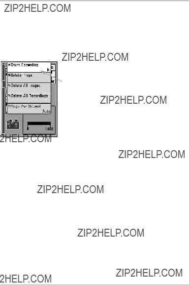
Start a Recording
From Snapshot and Recording View, select Start Recording from the
 Slider Bar
Notes about Recording:
Start recording:
1. From the Snapshot and Recording View, press the MENU key once t o o pen the Snap shot and Recording
2.Highlight Start Recording, a nd press the R IGHT Cu rsor key. A waypoint will also be created at the boat location, and the recording s hares the same file name (.SON).
Stop recording:
1.In any view, press the MENU key once to open the Snapshot and Recording
2.Highlight St op Recording a nd press the RIGHT Cursor key.
???While recording, press the EXIT key to exit the Snapshot and Recording
???The slider bar at the bottom of the Snapshot and Recording View shows the recording progress and remaining space on the MMC/SD card.
???Pings Per Sec ond: For maximum p erformance, keep th e Pings Per
Second setting on Auto (see Snapshot and Recording
???Viewing s aved Screen Snapshot s a nd Rec ording Pl ayback are not available while in recording mode.

Playback a Recording
 Recording File
Information
Highlighted File
Change Playback Settings
???Playback??? indicates the control head is playing a saved recording.
Open the
You can also use Freeze Frame and mark waypoints.
Delete a Recording
 From Snapshot and Recording View, select Delete Recording from the
Playback a Recording:
1. From the Snapshot and Recording View, pr ess th e UP or DOW N Cursor keys to scroll through the saved files and highlight a s aved Recording.
2. Press the RIGHT Cursor key.
Change Playback Settings:
1. Press th e MEN U k ey o nce to open th e S napshot and Recording
2.Use the
Stop Playback:
1. Press the MENU key once to open the S napshot and Recording
2.Highlight Stop Playback, and press the RIGHT Cursor key.
Delete a Recording:
highlight a saved Recording.
2.Press t he M enu k ey o nce, and select Delete Recording from the
RIGHT Cursor key.

Notes about Playback:
??????Playback??? will flash periodicallyon the screen to indicate that the control head is playing a saved recording and not a ???live??? view.
???Navigation is not affected by the Sonar Recording feature,but any active
navigation is cancelled a nd t humbnails and icons dis appear when Playback begins or ends.
???Playback is paused automatically at the end of the recording.
???Freeze Frame: Press the 4- WAY Cursor Control key to pause Playback and move the Active Cursor to a location on the sonar view. The Cursor dialog bo x will show the dep th a nd inf ormation fo r the loca tion y ou choose. Press Exit to resume Playback.
???Press t he MAR K key dur ing Play back to save a Scree n Snap shot
and/or m ark a w aypoint in th e view o r active cursor location y ou choose.
Recording Playback
 Name of recording
Time and Date  recording started
 Position where recording started
 Current Ping Rate
 Average Ping Rate
 Amount of time
remaining to play
Amount of time
Playback speed icons
already playedAmount of time remaining to play
Overall length of recording

Bird???s Eye View
Bird's Eye View shows a 3D perspective view of the track and the chart???s land contour from a point above andbehind theboat (the eye point). As the boat turns, the eye pointmoves to follow the boat.
???To shift the eye point position so that you can look off to the sides, or even behind the boat: Press the RIGHT or LEFT Cursor keys to turn the eye point right or left. Press the UP Cursor key to move the e ye point forward, a nd pr ess the DO WN Cu rsor ke y to move the eye point backward.
???Press the EXIT key to move t he eye poin t back to its original position behind and above the boat.
Depth 
Speed of Boat
Bird???s Eye View
 Latitude and
Longitude
Position
of Boat
 Boat Icon
 Land Contours
 Bearing of Boat
with Respect to
True North
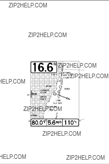
Chart View
Chart View shows cartography fr om t he bu
???Use the
???Press the ZOOM
???Press the INF O key to get i nformation about the chart objects near the cursor.
Chart View without Active Cursor, shown with
Depth 
Cartography

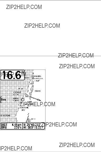
Chart View with Active Cursor, shown with
Depth
Cartography
Active Cursor
Map Scale
Latitude and
Longitude
Position
of Cursor
Distance to the Cursor and Bearing to Cursor
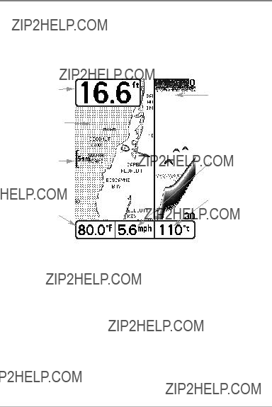
Chart/Sonar Combo View
Combo View is displayed as a split screen, with Chart View on the left and Sonar View on the right side of the screen. To chan ge the width of the Sonar
View Orientation
Both Chart and Combo Views allow you to choose the orientation of the view (see Navigation Menu Tab: Chart Orientation). In both orientations, the view pans automatically so that the boat is always centered on the display.
???
???
When the boat is stationary, it is drawn as a circle. When the boat is in motion, it takes on a boat shape, pointed in the direction of motion (always Up in the
Viewing Cartography
In the Chart or Combo Views there are several
Panning: Use the 4
Chart View with Cursor Present, shown with

Zooming: Press the Plus (+) key to ZoomIn and the Minus
Screen Snapshots and Recording Icons: When a wayp oint is created while Screen Sna pshot and Recording is act ive, t he waypoin t will appear as a snapshot icon or recording icon in char t vie ws. See Views: Snapshot and
Recording View for more information.
Chart Info: Press the INFO key to get deta iled information about the chart. If the cursor is active, you will see information ab out the chart objects located near the cursor.
If the cursor is n ot a ctive, t he Chart I nfo submenu will appear. Use th e 4
Control k ey to se lect the nearest port, the nearest tide st ation, or t he ne arest current station and see information about any of these objects.
NOTE: The
Nearest Port: The position and services information for the nearest port to your present position will be displayed. Press the EXIT key to remove the information box and the cursor bull???s eye will be centered over the port position. The cursor information boxes at the bottom of th e display will indicate the distance and bearing to the port from your present position.
Nearest Tide St ation: Tide information f or the n earest tide station to your present position will be displayed. This includes the position of the station and the t imes of the high and low tides f or to day???s dat e. A tide gra ph is als o displayed showing t he rise and fall of th e tides fo r the 24 h our time period encompassing the date. You can change the da te to look at tide information before or a fter the date displayed by pr essing the LEFT or RIGHT Cursor key
respectively. Press the EXIT key to remove the information box, and the cursor bull???s eye will be centered over the tide station position. The cursor information boxes at the bottom of the display indicate the distance and bearing to the tide station from your present position.
Nearest Current Station: Current information for the nearest current station to your present position will be displayed. This includes the position of the station and the current changes for today. Two graphs are also presented that show the time, direction, and flow s peed of the cu rrent changes for the 24 ho ur time period of today???s date. You can change the date to look at current information before or a fter the date displayed by pr essing the LEFT or RIGHT Cursor key respectively. Press the EXIT key to remove the information box, and the cursor bull???s eye will be centered over t he c urrent statio n po sition. The c ursor information boxes at the bottom of th e display will indicate the distance and bearing to the current station from your present position.

Introduction to Navigation
Use your 300 Series??? Fishfinder to mark waypoints at areas of interest and to navigate to those waypoints via a savable route. A route represents the shortest intended distance between waypoints. You can a lso v iew and save tr acks, which represent the actual path of the boat.
Waypoints, Routes, and Tracks
Waypoints are stored pos itions (lat itude, lo ngitude) t hat allo w you to mar k areas of interest or navigation points (i.e. a marker buoy, dock, or fishing hole). Your Fishfinder can store up to 3000 waypoints.
Routes link two or more waypoints together to create a path for navigation and are used in trip planning. You can linkindividual waypoints together by using the GOTO key. A route represents your intended navigation and shows the shortest path from each waypoint to the next. As you travel a route, staying on the route line is the most efficient way to ge t to your dest ination, although you shoul d always l ook out for obstac les not show n on the chart. Your 300 Se ries???
Fishfinder can store up to 50 routes that can each contain up to 50 waypoints.
Tracks consist of detailed posit ion history and are displayed as a breadcrumb trail of trackpoints. The Current Track shows the position history since the unit was powered up (maximum of 20,000 trackpoints displayed). You can clear the Current Track or save it at any time. Your 300 Series??? Fishfinder can store up to 5 0 s aved tr acks, each containing 2 0,000 trackpoints. The curr ent tr ack represents your actual path so far.

Waypoints, Routes, and Tracks
NOTE: When two or more waypoints overlap, or are displayed close together on a chart view, the screen will automatically
To view a Decluttered Waypointat full size, use the
Navigation Menu Tab: WaypointDecluttering to turn off this feature.
Save, Edit, or Delete a Waypoint
Save your current position as a waypoint:On any view, press the MARK key to save the currentposition of the boat as a waypoint.
Save the cursor position as a waypoint:On the Chart or Combo View, use the 4- WAY Cursor Control key to move the cursor to the position you want to save as a waypoint. Then pressthe MARK key to save the position as a waypoint.
Save a position from thesonar history: On any Sonar View, use the
NOTE: When you s ave a wa ypoint by any o f th ese methods, a numerical waypoint name is automatically assigned. You can edit the waypoint information later to give it a different name and select an ic on to represent it (see Program or Edit the waypoint fields).
Display the Waypoints Submenu: From any view, press the MENU key twice to display the Main Menu, then use the RIGHT Cursor key to select the Navigation tab. Select Waypoints, and press the RIGHT Cursor key to display the Waypoints submenu.
Program a specific position as a waypoint: To create a waypoint that is NOT your current position, from the Wa ypoints submenu select Create, and press the RIGHT Cursor key. Use the
Edit a w aypoint: From t he Waypoints submenu, select Edit and press the RIGHT Cursor key to display the saved waypoints list. Select the waypoint you want to edit and press the RIGHT Cursor key. Use the

To make it eas ier t o select a wa ypoint t o edit, select Sort By and press the RIGHT or LEFT Cursor keys to select a sort order:
???Name shows the waypoints alphabetically.
???Time shows the most
???Distance shows the closest waypoint first.
Program or Edit the waypoint fields: Use the
In t he Waypoint Name, L atitude, and Lon gitude fields, press the UP and DOWN Cursor keys to change the letter or number. All upper and lower case letters are available, as well as digits
In the Waypoint Icon field, press the UP and DOWN Cursor keys to change the icon used to represent the waypoint on the Combo and Chart Views. You can exit these fields with the LEFT and RIGHT Cursor keys or by pressing the EXIT key.
Delete a waypoint: From the Waypoints submenu, select Delete, and press the RIGHT Cursor key to display the saved waypoints list. Select the waypoint you want to delete, then press the RIGHT Cursor key. You will be asked to confirm deletion before the waypoint is permanently deleted.
Navigate to a Waypoint or Position
Navigate t o th e c ursor pos ition: From the C hart o r Co mbo View, use the
Navigate to a specified waypoint: Press the GOTO key. Press the DOWN Cursor key to highlight a waypoint from the saved waypoints list, and press the RIGHT Cursor key to start navigation.
NOTE: By repeating the previous instructions, you can add more waypoints to create a longer
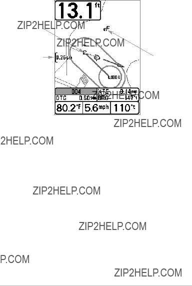
Chart View
Waypoint
Decluttered
MapWaypoints
Scale
Skipping a waypoint: From the Navigation
Cancel navigation: From t he Navigation

Add a Waypoint Target or Trolling Grid
The Waypoint Target shows a target consisting of concentric circles in various distance ranges centered on the waypoint you choose. The Trolling Grid shows various di stance ranges in grid format from the waypo int y ou c hoose. The trolling grid can be used as a guide when trolling around a waypoint.
Chart View with Target
Add a Wayp oint T arget: From the Waypoints submenu, s elect Target, a nd press the RIGHT Cursor key to display the saved w aypoints list . Selec t a waypoint and press the RIGHT Cursor key.
 Waypoint
Target
Chart View with Grid
Trolling
Grid
Add a Trolling Grid: From the Waypoints submenu, select Grid, an d p ress the RIGHT Cursor k ey to d isplay th e s aved waypoints lis t. Select a waypoint and press the RIGHT Cursor key. The grid can also be rotated t o any he ading by adjusting the Grid Rotation setting on the Navigation Main Menu.
Remove T arget or Tro lling Grid: Press the MENU key once, and choose Remove Target or Remo ve Gri d f rom the Navigation
NOTE: Only one waypoint can have either a target ora grid applied to it at one time. If you apply a target or a grid to a new waypoint, the original waypoint will lose its target or grid.
NOTE: The spacing of the rings on the waypoint target and the spacing of the grid lines on the trolling grid are the same as the length of the scale bar on the left edge of the display. Zooming in or out will decrease or increase the spacing, respectively.

Save, Edit, or Delete a Route
Save the current route: While you are navigating, t he cur rent route ca n be saved. From the Navigation
Display the Routes submenu: From any view, press the MENU key twice to display t he Main Menu, then press the RIGH T Cursor key to select t he Navigation tab. Press the DOWN Cursor key until Routes is highlighted, and press the RIGHT Cursor key to display the Routes submenu.
Create a route: From the Routes submenu, select Create and press the RIGHT Cursor key. A Route Edit dialog box will be displayed with an empty route. You can name the route, add waypoints to the route from the saved waypoints list, and order the waypoints in t he route using the
Edit a saved route: From the Routes submenu, select Edit and press the RIGHT Cursor key. A Route Edit dialog box will be displayed. Select the route you want to edit and press the RIGHT Cursor key.
Edit waypoint order in a route: From the Route Edit dialog box, highlight a waypoint in the I n Route list , and pr ess the RIGHT Cur sor key to acc ess the Waypoint In Route submenu. From this submenu, you can move the waypoint up or down in the route order or delete it from the list.
Delete a saved route: From the Routes submenu, select Delete and press the RIGHT Cursor key. Select t he route you want to d elete and p ress the R IGHT Cursor key. You w ill be as ked to c onfirm your ch oice by p ressing the RIGH T Cursor key again before the route is deleted.
Travel a save d route: From the Routes submenu, select Travel, and press the RIGHT Cursor key. The saved routes list will appear. Select the route you want to travel, and press the RIGHT Cursor key to make this route the current route and begin navigation. You may also travel the route in forward or reverse order by changing the Direction setting in the saved routes list.
Route Info: From the Routes submenu, select Info, and press the RIGHT Cursor key. The s aved routes list w ill appear. Select a rou te, and press the RIGHT Cursor key. The following information will be displayed for the route you select: The waypoints in the route, with the distance and bearing from each waypoint to the next, as well as the distance and bearing from the current position to the first waypoint in the route.
Save or Clear a Current Track
Save t he cur rent t rack: From the N avigation
NOTE: When you save a track, a name is automatically assigned. The track name consists of a date/time stamp, but can be
Clear t he curr ent tr ack: From t he Naviga tion
Edit, Delete, or Hide Saved Tracks
Display the Saved Tracks Submenu: From any view, press the MENU key twice to dis play t he M ain Menu, t hen press th e RIGH T C ursor k ey to select the Navigation tab. Select Saved Tracks, and press the RIGHT Cursor key to display the Saved Tracks submenu.
Edit a saved t rack: From the Saved Tracks submenu, select Edit, and press the RIGHT Cursor key to displaythe saved trackslist. Select the track you want to edit and press the RIGHT Cursor key.
When the Edit Trackdialog box appears, use the Cursor keys to move between fields. In the Name field, the UP and DOWN Cursor keys change the letter or number. All upper and lower case letters are available,as well as digits

Delete a saved track: From the Saved Tracks submenu, select Delete, and press the RIGHT Cursor key to display the saved tracks list. Select the track you want to delete and press the RIGHT Cursor key. You will be asked to confirm deletion before the track is permanently deleted.
Hide or display a saved track: From the Saved Tracks submenu, select Visibility, and press the RIGHT Cursor key to display the saved tracks list. Select the track you want to hide or display and press the RIGHT or LEFT Cursor keys to select Hidden or Visible. Press the EXIT key to return to the Saved Tracks submenu.
Add Maps to Your Fishfinder
Your 300 Series??? Fishfinder includes a
Southeast Asia, including Australia and New Zealand (International models).
You can a lso purchase MMC/SD cards with additional chart informationfor a particularlocation. When you install the MMC/SD cards in your control head, your
300 Series??? Fishfinder will retrievethat chart and display it automatically.
NOTE: The MMC/SD Cards require a separate purchase. Your 300 Series??? Fishfinder supports Navionics?? Gold, HotMaps??? and HotMaps??? Premium on MMC or SD card media. Your 300 Series??? Fishfinder does NOT support Navionics?? Classic Charts or Platinum??? Cartography.
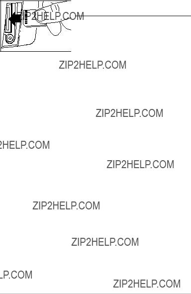
Inserting an MMC/SD
into the Card Slot
To insert an MMC/SD card:
1.Remove the MMC/SD slot cover.
2.Position the MMC/SD card so that the label faces the right side of the unit, and insert the card into the slot. Press down on the card until it clicks into place.
3.Close the slot cover and turn the knob just 1/4 of a turn to close. Do NOT overtighten, as this will n ot i mprove water resistance an d may damage the cover.
4.To Remove: Press the MMC/SD card into the slot and then release. The card will eject, and you can then pull the card from the slot.
Export Navigation Data
You can export all saved Tracks, Waypoints, and Routes from your Fishfinder to an
To Export All Navigation Data:
1.Make sure that an
2.Press the MENU key twic e to acc ess the Main Menu, then press the RIGHT Cursor key until the Navigation tab is selected.
3. Highlight Export All Nav Dat a and p ress th e RIGH T Cur sor key. The Confirm dialog box wil l a ppear. To confirm expo rt, press the RIGHT Cursor key once more. To cancel export, press the LEFT Cursor key.
NOTE: If an MMC/SD card is not installed, an error message will be displayed. Insert the MMC/SD card and try again.
NOTE: The MMC/SD cards and MMC/SD Card Reader require separate purchasesThe. MMC/SD Card Re ader accessory can be us ed i n conjunction w ith y our personal computer t o view and o rganize y our ex ported n avigation data. T o pur chase this accessory, v isit o ur w eb site at www.humminbird.com or contact our Customer Resource Center at

What???s on the 300 Series??? Control Head
Your 300 Series??? Fishfinder interface is easy to use. A combination of keys and special features allows you to control what you see on the display. Refer to the following illustration, and see Key Functions for more information.
1

Key Functions
Your Fishfinder user interface c onsists of a set of ea
POWER/LIGHT Key
The POWER/LIGHT key is used to power the Fishfinder on and off. You can also use t he POWER/LIGHT key to adjust the backlight and contrast of the display.
Power On the control head: Press the POWER/LIGHT key to power on the unit. When the Title screen is displayed, press the MENU key to access the
Power Off the con trol head: Press and hold the PO WER/LIGHT key for 3 seconds. A message will appear to indicate how many seconds there are until shutdown o ccurs. To ensure that shutdown occurs pro perly a nd an y m enu settings will be s aved, your Fishfinder should always be turned off using the POWER/LIGHT key.
Adjust the B acklight or the Display Contrast: Press the POWER/LIGHT key to access the Light and Co ntrast s ubmenu. U se the 4
NOTE: Your 30 0 Seri es??? Fishfinder w ill s tart up with the backlight on and will automatically turn it off to conserve power.
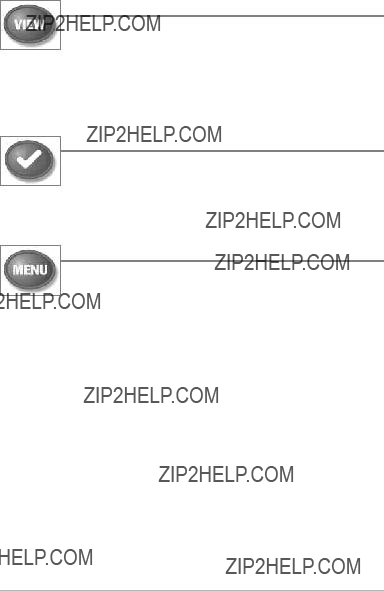
VIEW Key
The VIEW key is used to cycle through all available views. Press the VIEW key to advance to the next view. Repeatedly pressing VIEW cycles through all views available. Views can be hidden to optimize the system to
your fishing requirements (seeViews or Views Menu Tab).
NOTE: Press the EXIT key to cycle through the views in reverse order.
INFO Key
Press the INFO key while in Bird's Eye, Chart, or Combo View to display information about objects that are near an active cursor. If the cursor is not ac tive, the Ch art In fo sub menu w ill be
displayed. See Views: Viewing Cartography for more information.
MENU Key
The M ENU k ey is used to ac cess the m enu system. See The Menu System for more information.
???
???
???Main Menu: Press the MENU key twice in any view to access the Main Menu, which is organized un der ta bbed head ings t o help you find a specific menu item quickly.

(LEFT, RIGHT, UP, or DOWN Cursor keys)
The
???Menu Selection: Press the DOWN o r UP Cursor ke ys t o highlight a menu option, then pr ess t he RIGHT or LEFT Cursor keys to c hange a menu setting. The changes will be activated and saved immediately.
???Freeze Frame: In Sonar View, press any arr ow on t he 4
???Active Cursor: Press any arrow on the
???In any Chart View, the
NOTE: In Freeze Frame or Active Cursor mode, you can also make the cursor move diagonally by pressing in between two of the arrows on the
???Bird???s Eye View: The
???Snapshot and Recording View: Press the UP or DOWN Cursor keys to highlight a recording icon, and then press the Right Cursor key to start recording playback. Press the Right and Left Cursor keys to control the speed of playback.
MARK Key
Press the MARK key while in any view to mark the position of a waypoint. T he MARK key fu nction wo rks if y ou have the GPS receiver connected.
???Active Cursor: The waypoint will be marked at the cursor location.
???Without Active Cursor: The wa ypoint w ill b e m arked at the boat location.
???If Screen Snapshot is active, a waypoint will be created, and a screen snapshot will also be saved to the
Views: Snapshot and Recording View). Navigation is not affected by the Screen Snapshot feature.
NOTE: If S creen Snapshot is e nabled but there is not a GPS receive r connected, pressing the MARK key will capture the screen image and display an error saying that a GPS position fix is required to create a waypoint.
NOTE: You must have an
GOTO Key
The GO TO key h as mu ltiple fu nctions, w hich d epend on the situation.
??? Active Cur sor: Press the GOTO k ey w hile in any view to cr eate a waypoint and start navigation towards that waypoint.
???Without Act ive C ursor: Press t he GOTO ke y to d isplay the sa ved waypoints list, and then highlight a waypoint. Press the RIGHT C ursor key to begin navigation.
ZOOM
In any of the Navigation Views or the Sonar Zoom View, press the
EXIT Key
The EXIT key has multiple fu nctions, which depend o n the situation:
???If an alarm is sounding, press the EXIT key to cancel the alarm.
???If a menu tab is selected, press the EXIT key to exit the menu mode and return to the view.
???If a menu is active, press the EXIT key to return to the previous level in the menu system.
???From any view, press the EXIT key to cycle through the available views in reverse order.
???If Freeze Frame is active , press th e EXI T key to return to a scrolling display.
???If the Cursor is active, press the EXIT key to remove the cursor from the display.
(MMC)/SD Slot
Inserting an MMC/SD
into the Card Slot
The
NOTE: The MMC/SD Cards require a separate purchase. For more information, visit our web site a t www.humminbird.com or contact our Customer Resource Cent er at

The Menu System
The Menu System is divided into
???
???
???Main Menu: The Main Menu is a standard set of menu settings which
are organized under the f ollowing ta bbed head ings: Ala rms, Sonar, Navigation, Chart, Setup, and Views.
NOTE: The
simplified by setting the User Mode to Advanced or Normal (see Main Menu: User Mode).

Press the MENU key during t he power on seq uence t o view the
Normal
Use Normal for
To exit Normal operation, power off your Fishfinder.
Simulator
Use Simulator to learn how to use your Fishfinder before taking your boat on the water. The Simulator is a v ery powerful tool that provides a
Simulator
We recommend going through this manual while using the Simulator, since all of the menus function a nd affect the display in the sa me way as they would i n Nor mal operation. An y m enu c hanges you m ake will be saved for later use.
NOTE: It is i mportant to s elect S imulator manually from the
A message w ill ap pear o ften o n the display to indicate Simulator mode.
To exit Simulator, power off your Fishfinder.
System Status
Use System Status to view system connections and to conduct a unit
After you select Sy stem St atus from th e St
???Self Test
???Accessory Test
???GPS Diagnostic View
To exit System Status, power off your Fishfinder.
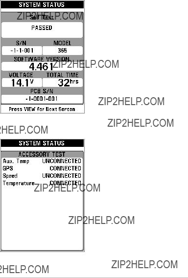
Self Test Screen
Accessory Test
Self Test displays results from the internal diagnostic s elf test, in cluding unit s erial number, Printed Circuit Board (PCB) serial number, software revision, total hours of operation, and the input voltage.
Accessory T est lists t he accessories connected to the system.
NOTE: The speed accessory will be detected only if the paddlewheel has moved si nce yo ur Fishfinder was powered up.

GPS Diagnostic View shows a sky char t and numerical data from the GPS receiver. The sky chart shows the location of each visible GPS satellite with its satellite number and a s ignal strength bar. A dark gray ba r indicates that the satellite is being us ed t o determine y our curren t positio n. A light gray bar indicates that the satellite is being monitored, but is not yet being used.
This vi ew also report s t he current position, lo cal tim e a nd da te, a nd other numeric information. The current GPS Fix Type is reported as No Fix, 2D Fix, 3D Fix, or Enhanced. An Enhanced fix has been augmented using information from WAAS, EG NOS, or MSAS. A 3D or Enh anced Fix is required f or naviga tion. HDOP (the Horizontal Dilution of Precis ion) is a GPS system p arameter which depends on t he current satellite configu ration. HDOP is used to c alculate the Estimated Position Error.
GPS Diagnostic View
Sky Chart
 Fix Type
Satellite Being
MonitoredSatellite
Being Used
Current Latitude
and Longitude
The
To use an
1.In any view, press the MENU key once.
2.Press t he UP or DOWN C ursor keys to h ighlight an
NOTE: The
3.Reactivate the
Total Screen Update - When you c hange a ny menu set tings that a ffect the current view, the view will update immediately (i.e. you don???t have to exit the menu to apply the change to the screen).
Menu options can be simplified or expanded b y setting the U ser Mode to Normal or Advanced. See Main Menu: User Mode for details.

Main Menu
The M ain Me nu pr ovides th e sta ndard s et of menu options, inc luding the settings that a re changed less f requently. The M ain Men u is organized under the following tabs to help you find a specific m enu it em q uickly: Al arms, Sonar, Navigation, Chart, Setup, and Views.
NOTE: Menu options can be expanded orsimplifiedby setting the User Mode t o Advanced or Normal. See
Main Menu: User Mode for details.
Main Menu (Normal User Mode)
To use the Main Menu:
1.In any view, press the MENU key twice.
2.Press the RIGHT or LEFT Cursor keys to highlight a menu tab.
3.Press the D OWN or UP Cur sor keys to select a sp ecific menu option under that tab.
4.Press the RIGHT or LEFT Cursor keys again to change a menu setting.
???A down arrow at the bottom of amenu means that you canscroll to additional menu options using the DOWNCursor key.
???A rightorleft arrowon a menu option means that you can use the RIGHT or LEFT Cursor keys tomake changes or to see more information.
???Press the EXIT keyto move quicklyto the top of the tab.
Total Screen Update - When you change any menu settings that affect the current view, the view will update immediately (i.e. you don???t have to exit the menu to apply the change to the screen).

Quick Tips for the Main Menu
???From anymenu option on a menu tab, press the EXIT key to jump directly to the top of the tab.
???From the bottom of a menu t ab, press the DOWN Cu rsor key to jump directly to the top of the tab.
???From the top of a menu tab, press the LEFT or RIGHT Cursor keys to scroll to the next tab. You can also jump to the beginning or end of the tab rotation by repeatedly pressing the RIGHT or LEFT Cursor keys.
???If there is a down arrow at the bottom of a menu tab, press the DOWN
Cursor key to scroll to additional menu options.
???If there is aright or left arrow on a menu option, press the RIGHTor LEFT Cursor keys to make setting changes or see more information.
???If you press MENU or EXIT to leave theMain Menu and then return to the Main Menu at a later time, the menu will open to the same tab as thelast time the Main Menu was displayed.
Note for all Menu Settings
The settings in all menus are adjusted in the same way. Simply use the
Below is an example of how the menu o ptions are d escribed in this manual. Each description shows the menu optio n appearance, the availa ble settings, and the specific control head s ettings r equired (i.e. ad vanced user mode, international only, view, navigation, or accesssory).
Menu Option Name
Setup User Mode and other control head requirements
 Available Menu
Settings
and Default
 Setting Description
Menu Option as it appears on the screen

User Mode (Normal or Advanced)
Menu options can be simplified or expanded by settingyour Fishfinder User Mode to Normal or Advanced.
Normal Mode is the default setting when you first power on your 300 Series??? Fishfinder. Normal mode is provided for users who w ant greater simplicity and fewermenu choices.
Advanced Mode is provided for users who want the highest level of control over the Fishfinder. Several menu settings are added to the Main Menu when the User Mode is changed to Advanced.
To change the User Mode setting:
1.Press the MENU key twice to access the Main Menu.
2.Press the RIGHT Cursor key until the Setup tab is selected.
3.Press the DOWN Cursor key to highlight User Mode on the Setup main menu.
4.Press the LEFT or RIGHT Cursor keys to change the User Mode setting.
(Normal, Advanced, Default = Normal)
NOTE: Any changes made while in Advanced Mode will remain in effect after you switch back to Normal Mode.
For example, the Select Readouts menu option is available when the UserMode is set to Advanced. If you change the Select Readouts settings while operating in Advanced User mode, the Select Readouts you choose will continue to display on the screen even if you switch back to Normal User Mode.

Sonar Tab, Normal Mode
Sonar Tab, Advanced Mode

Sonar
(Sonar Views only)
The Sonar
NOTE: Menu options can be expanded or simplified by setting the Fishfinder User Mode to Advanced or Normal. See Main Menu: User Mode for details.
Sonar

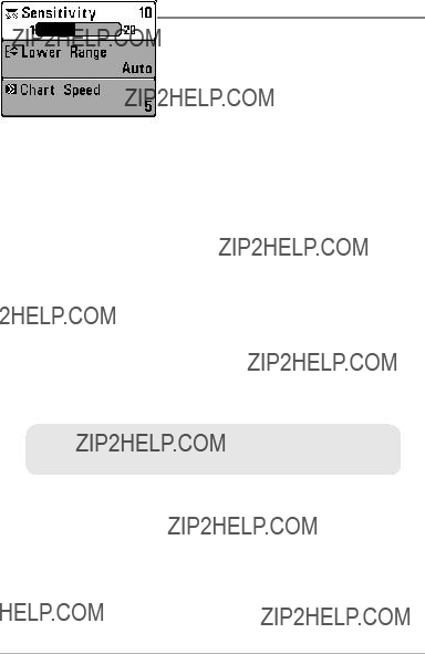
Sensitivity
Settings: Low = 1, High = 20; Default = 10
Sensitivity controls how much detail is shown on the display and w ill adjust the sensitivity of all sonar frequencies.
When operating in very clear water or greater depths, increase the sensitivity to see weaker returns that may be of interest . If the sensitivity is adjusted too high, the display may become too cluttered.
Decrease t he s ensitivity to elimina te th e clut ter fro m the d isplay that is sometimes present in murky or muddy water. If Sensitivity is adjusted too low, the display may not show many sonar returns that could be fish.
NOTE: The Sensitivity setting is a global setting and will adjust the sensitivity of all sonar frequencies.
Sensitivity at Low Sensitivity at Medium Sensitivity at High
Upper Range
(Advanced: Sonar, Split Sonar, Circular Flasher, and Big Digits Views only)
Settings: 0 to 990 ft or 0 to 327 m [International Models only]; Default = 0
Upper Range sets the shallowestdepth range that will be displayed onthe Sonar, Split Sonar, Circular Flasher, and Big Digits Views. Upper Range is often used with Lower Range.
For example, if you are only interested in the area between 20 and 50 feet deep, you should set the Upper Depth Range to 20 and the Lower Depth Range to 50. The Sonar View will then show the 30 foot area between 20 and 50 and will not show the surfac e or the bottom (assuming the bottom is deeper than 50 feet). Greater detail will be shown for the area between 20 and 50 feet.
NOTE: A minimum distance of 10 feet will be maint ained between the Upper and Lower Range regardless of the manual settings entered.
Lower Range
Settings: AUTO, 10 to 1000 ft, 3 to 330 m [International
Models only]; Default = AUTO
Lower Range sets the deepest depth range that will be displayed by the unit.
Auto: The L ower Range will be adjus ted by the unit to f ollow the bottom automatically. Auto is the default setting.
Manual: You can adjust the Lower Range to lock the unit on a particular depth. ???M??? will be displayed in the lower right corner of the screen to indicate the unit is in Ma nual mode. Adjus t the Upper an d Lo wer Ra nge to gether to view a specific depth range, especially when looking for fish or bottom structure.
For example, if you are fishing in 60 feet of water but are only interest ed in the first 30 feet (surface to a depth of 30 fe et), you should set the Lower Depth Range limit to 30. The display will show the 0 to 30 foot range, which allows you to see a more detailed view than you would see if the dis play went all the way to the bottom.
NOTE: A minimum distance of 10 feet will be maintained between the Upper and Lower Range regardless of the manual settings entered.

Chart Speed
Settings:
Fastest; Default = 5
Chart Speed determines the speed at which the sonar information moves across the display, and consequently the amount of detail shown.
A faster speed shows more information and is preferr ed by most ang lers; however,the sonar information movesacross the display quickly. A slower speed keeps th e i nformation on the display longer, but t he bottom and fi sh details become compressed and may be dif ficult to interpret. Regardless of the Chart Speed setting, the RTS Window??? will update at the maximum rate possible for the depth conditions.
 Bottom View
Settings: Inver se, Structure I D??, WhiteLine???, Bottom
Black; Default = Inverse
Bottom View selects the method used to represent bottom and structure on the display. See What???s on the Sonar Dis play: Bo ttom Pr esentation for more information.
Bottom Range
(Sonar Zoom View only when Bottom Lock is On)
Settings: 10 - 6 0 feet,
Bottom Range allows you to control how much of the water column, measured up from the bottom, is shown in the Sonar Zoom View. Choose a small value to see
NOTE: It is possible to set the Bottom Range to be greater than thedepth. In this case, you may see surface clutter in a wavy band that mirrorschanges in the depth.

Bottom Lock
(Sonar Zoom View only)
Settings: Off, On; Default = Off
Bottom Lock changes the mode of t he zoomed view in the Sonar Zoom View. Bottom Lock continuously graphs the bottom at a constant point on the display regardless of changes in depth. This ???flattens??? out the bottom contour but is effective at showing fish on or near the bottom.
Cancel Navigation
(only when Navigating)
Settings: Follow screen instructions to activate.
Cancel Navigation discards the current route and exits Navigation Mode. This menu option will only appear w hen you are currently navigating a route. This will not delete a

Navigation
(Navigation Views only)
The Navigation X
NOTE: Menu options will vary depending on system settings, such as whetheryou are currently navigating.
Navigation

Waypoint [Name]
(Only with an active cursor on a waypoint)
Settings: Edit, Delete, Target, Grid
Waypoint [Name] allows you to view the Waypoints submenu for the waypoint under your cursor. You can move the cursor onto an existing waypoint and press the MENU key once, or use Cursor to Waypoint to select a waypoint from the saved waypoints list.
NOTE: See Introduction to Navigation for more Waypoints information.
The Waypoint Submenu contains the following menu options:
Edit allows you to edit the Name, Position (Latitude and Longitude), and select the Icon that will be used to represent the waypoint in the Chart and Combo Views.
Delete allows you to delete a waypoint from the saved waypoints list.
Target allows you to apply a ta rget to a waypoint selected from the saved waypoints list.
Grid allows you to apply a trolling grid to a waypoint selected from the saved waypoints list.
Cursor to Waypoint
(Chart or Combo View only)
Settings: Follow screen instructions to activate.
Cursor to Waypoint allows you to quic kly move the cur sor to any saved waypoint so that you can locate it or ed it it. This
Save Current Track
Settings: Follow screen instructions to activate.
Save Current Track allows you to save the cu rrent track on the displa y. After the current track is saved, a new current t rack is star ted. Save Curr ent Track appears on the Navigation
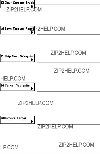
Clear Current Track
Settings: Follow screen instructions to activate.
Clear Current Track allows you t o clear the current track on the display and start a new track at the present position.
Save Current Route
(only when Navigating)
Settings: Follow screen instructions to activate.
Save Current Route allows you to save the current route being displayed. This menu option will only appear when you are currently navigating a route.
Skip Next Waypoint
(only when Navigating)
Settings: Follow screen instructions to activate.
Skip Next Waypoint removes the next waypoint from the cur rent route. This menu option will only appear when you are currently navigating a route.
Cancel Navigation
(only when Navigating)
Settings: Follow screen instructions to activate.
Cancel Navigation discards the current route and exits Navigation Mode. This menu option will only appear when you are currently navigating a route. This will not delete a
Remove Target
(only if a Target is Active)
Settings: Press the RIGHT Cursor key to activate.
Remove Target removes the waypoint target from the display. This menu option will only appear when a target has already been applied to a waypoint.
NOTE: See Introduction to Navigation: Add a Waypoint Target or Troling Gridfor more information.

Remove Grid
(only if a Grid is Active)
Settings: Press the RIGHT Cursor key to activate.
Remove Grid removes the waypoint grid from the display. This menu option will only appear when a grid has already been applied to a waypoint.
NOTE: See Introduction to Navigation: Add a Waypoint Target or Trolling Grid for more information.
Sonar Window
(Combo View only)
Settings: Wide, Medium, Narrow; Default = Medium
Sonar Window sets the size of the Sonar Window in the Co mbo View. Sonar Window can only be accessed from the Combo View.
Waypoint [Name]
(Most
Settings: Edit, Delete, Go To, Target, Grid
Waypoint [Name] allows you to view the waypoints sub menu for the most recently created waypoint. You must have pressed the MARK key at least once since you last powered up the Fishfinder for this menu option to appear.
NOTE: See Introduction to Navigation for more information.
The Waypoint Submenu contains the following menu options:
Edit allows you to edit the Name, Position (Latitude and Longitude), and select the Icon that will be used to represent the waypoint in the Chart and Combo Views.
Delete allows you to delete a waypoint from the saved waypoints list.
Go To allows you to select a waypoint and start navigation toward that waypoint, or add that waypoint to the end of the current route.
Target allows you t o app ly a ta rget t o a waypoint selected fr om the saved waypoints list.
Grid allows you to apply a trolling grid to a waypoint selected from the saved waypoints list.
Snapshot and Recording
(Snapshot and Recording View only)
The Snapshot and Recording
NOTE: For more information, see Views: Snapshot and Recording View.
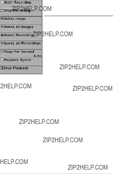
Snapshot and Recording

Start Recording
Settings: Press the RIGHT Cursor key to activate.
Start Recording allows y ou t o st art son ar recording from t he Snapshot and Recording View. This menu option is only available when an
MMC/SD card is installed and Snapshot and Recording View is on the screen.
Stop Recording
Settings: Press the RIGHT Cursor key to activate.
Stop Recording allows you to s top sonar recording. This menu op tion is only available when an
Delete Image
Recording View only)
Settings: Follow screen instructions to activate.
Delete Image allows you to delete a s ingle screen capture image. This menu option is only available when an
Delete All Images
Settings: Follow screen instructions to activate.
Delete All Images allows you to delete allthe images at once. This menu option is o nly a vailable when an op
 Delete Recording
Settings: Follow screen instructions to activate.
Delete Re cording allows you to delete a single sona r recording. This menu option is only available when an
Snapshot a nd R ecording View is on th e screen, an d you have s elected a recording file.
 Delete All Recordings
Settings: Follow screen instructions to activate.
Delete A ll Recor dings allows you to delete a ll th e recordings at once. This menu opti on is only available w hen an o
 Pings Per Second
Settings:
Pings Per Sec ond allows you to s pecify th e p ing rat e f or a n active sonar recording.
NOTE: Pings Per Second is ava ilable when an
Auto is the default setting for Pings Per Second and automatically adjusts the ping rate for best recording quality. If there is limited memory on your MMC/SD card, you can slow the ping rate by setting the Pings Per Second manually, but the recording will capt ure less sonar deta il. For maximum performance, keep the Pings Per Second setting on Auto.
Playback Speed
Recording View only)
Settings: Record, Rewind1, Rewind2, Slow Play Reverse,
Pause, Sl ow Play, Normal Play, Fast Forward1, F ast
Forward2, Stop
Playback Speed allows you to specify the playback speed for a sonar recording from the Snapshot and Recording View. This menu option is only a vailable when an
Playback Speed Icons:
NOTE: You can also change playback speed in the Snapshot and Recording View using the Left and Right Cursor keys, although you cannot skip to the beginning or endof a recording using these keys.
NOTE: Sonar c hart sp eed is i ncreased d uring Fast Forward and reversed during Rewind. This may result in a reduced quality sonar image, since at higher speeds, not every sonar return can be processed.

Stop Playback
Settings: Press the RIGHT Cursor key to activate.
Stop Playback allows you to stop playback of a sonar recording from any view. This menu option is only available when an
NOTE: During playback, the amount of time/memory left to play is indicated by the
status bar. For more information, see Views: Snapshot and Recording View.

Alarms Menu Tab
From a ny vie w, press th e M ENU ke y tw ice to access the Main Menu. The Alarms tab will be the default selection.
NOTE: When an alarm is triggered, you can silence it by pressing any key. The alarm will be silenced, and will not be triggered again until a new instance of the alarm condition is detected.
Alarms Menu

Depth Alarm
Settings: OFF , 1 to 100 f eet, or 0.5 to 30 meters [International Models only]; Default = OFF
Depth Alarm sounds when the depth becomes equal to or less than the menu setting.
Fish ID Alarm
Settings: Off, All, Large/Medium, Large; Default = Off
Fish ID Alarm sounds when the Fishfinder detects fish that correspond to the alarm setting. Fish ID Alarm will only sound if Fish ID+??? is on. For example, if you've set the Fish ID Alarm to sound for Large fish only, the Fish ID alarm will sound when a
Off
All
Large/Medium
Large
Low Battery Alarm
Settings: Off, 8.5V - 13.5V; Default = Off
Low Battery Alarm sounds when the in put battery voltage is equal to or less than the menu setting. The battery alarm will only sound for the battery that is connected to the Fishfinder. The Low Battery Alarm should be set to warn you when the battery volt age drops be low th e safety m argin th at y ou have determined.
For example, if you are running a trolling motor (battery operated), you would want to set the Low Battery Alarm to sound before the battery voltage drops too low for it to be used to start your main,

Temp. Alarm
Settings: Off, 3
Temp. Alarm sounds when t he water temperature detected by the Fishfinder reaches the Temp. Alarm setting, which is either set in d egrees Fahrenheit or Celsius [International Models only].
For example, if the Temp. Alarm is set to 58 degrees Fahrenheit, andthe watertemperature falls from 60 degrees to 58 de grees, the Temp. Alarm will sound. Similarly, if the wate r temperature rises from 56 degrees to 58 degrees, the Temp. Alarm will also sound.
Off Course Alarm
Settings: Off, 25 to 3000 ft, 10 to 1000 m [International
Models only]; Default = 300 ft, 100 m
Off Course Alarm allows you t o set how far the bo at is allo wed to mo ve off course before the Off Course Alarm will sound during navigation.
Off Course
Limits
Arrival Alarm
Circle

Arrival Alarm
Settings: Off, 25 to 3000 ft, 10 to 1000 m [International
Models only]; Default = 150 ft, 50 m
Arrival Alarm sounds when the boat has either exceeded the d istance to the destination waypoint, or has ent ered th e Arr ival Alar m C ircle, b ased on the menu setting when navigating. Arrival Alarm allows you to set how close the boat must be to the destination waypoint before the Arrival Alarm will sound.
Drift Alarm
Settings; Off, 25 to 3000 ft, 10 to 1000 m [International
Models only]; Default = Off
Drift Alarm allows you to set the size of a perimeter around the boat???s anchored position. If the anchored boat drifts ou tside of that per imeter, the Drift Ala rm will sound.
Drift Alarm Perimeter
Drift
Alarm
Circle
Alarm Tone
Settings: High, Medium, Low; Default = Medium
Alarm Tone selects the pitch of the alarm sound. A brief tone will be produced as you adjust the Alarm Tone so thatyou can select the tone that youcan hear best.

Sonar Menu Tab
Press the MENU key twice to access the Main Menu a nd th en pr ess th e RIGHT C ursor key until the Sonar tab is selected.
NOTE: Menu options can be expanded or simplified by setting the User Mode to Advanced or Normal. See Main Menu: User Mode for details.
Sonar Menu, Advanced Mode
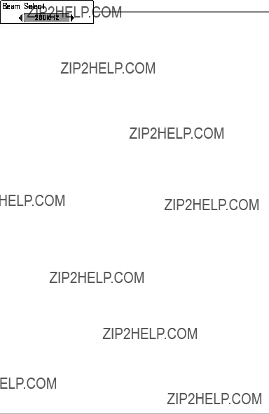
Beam Select
Settings: 200/83 kHz, 200 kHz, 83 kHz; Default = 200 kHz
Beam Select sets which sonar returns from the transducer will be displayed on the screen.
When set to 200/83 kHz, the returns from both beams are blended by starting with the 83 kHz wide beam return, dimming it, and then overlaying it with the
200 kHz narrow beam return. The darker 200 kHz narrow beam sonar returns will stand out from the paler 83 kHz wide beam sonar returns. The Split Sonar View continues to display the sonar returns from each beam in their respective windows. The blended informat ion is shown in the Son ar View, Sona r Zoom View, and the Big Digits View. The RTS Windo w??? in the Sonar View and the Circular Flasher View will only show the returns from the 200 kHz narrow beam.
When set to 200 kHz, only the returns fro m the 200 kHz narrow beam will be displayed in the Sonar View, the Sonar Zoom View, the Big Digits View, and the Circular Flasher View. The SplitSonar View will continue to display returns from both beams in their respective windows. The RTS Window??? in the Sonar View will display the returns from the 200 kHz narrow beam.
When set to 83 kHz, the returns from the 83 kHz wide beam will be displayed in the Sonar View, the Sonar Zoom View, the Big Digits View, and the Circular Flasher View. The Split Sonar View will continue to display returns from both beams in their respective windows. The RTS Window??? will display the returns from the 83 kHz wide beam.

Surface Clutter
Settings: Low = 1 to High = 10; Default = 5
Surface Clutter adjusts the filter that removes surface clutter noise caused by algae and aer ation. The lower t he set ting, th e less sur face clutter will be displayed.
Surface Clutter
 Surface
Clutter
SwitchFire???
Settings: Clear Mode, Max Mode; Default = Clear Mode
SwitchFire??? controls how the sonar returns are displayed in the Sonar Views.
Choose Max Mode to see only raw sonar returns on the d isplay. When Max Mode is selected, you will see the maximum sonar information available within the transducer beam, so more fish arches and better jig tracking are shown.
Choose Clear Mode to see less c lutter and mo re fish size a ccuracy on the display. When Clear Mode is selected, the clutter is filtered, and sonar returns are interpreted to provide more details about the objects within the transducer beam, regardless of their locat ion. In other words, a large arch on the display means a large fish has been detected.

Fish ID+???
Settings: Off, On; Default = Off
Fish ID+??? uses advanced signal processing to interpret sonar returns and will display a Fish Symbol when very selective requirements are met. When a fish is detected, a fish icon and its depth are displayed above the return that has been classified as being a fish. Three different fish size icons represent the intensity of the sonar return and provide an indicator ofrelative fish size.
DualBeam PLUS ??? sonar models represent targets detect ed in th e 200 kHz narrow beam as Shaded Fish Symbols and targets detected in the 83 kHz wide beam as Hollow Fish Symbols.
When Fish ID+??? is t urned o ff, t he Fishfin der shows o nly the r aw son ar returns on the display. These returns will often result in ???arches??? forming on the display, indicating potential targets. D ue t o t he t ransducer b eam angle, the distance to a f ish decreas es as the fish moves into the beam, and then increases as it moves out again, creating a Fish Arch when this distance change is shown on the display. Boat speed, chart speed, and the position of the fish within the sonar beam greatly affect the shape of the arch.
Transducer Cone and Fish Arches
Fish ID Sensitivity
Settings: Low = 1, High = 10; Default = 5
Fish ID Sensitivity adjusts the threshold of the Fish ID+??? detection algorithms. Selecting a higher setting allows weaker returns to be displayed as fish. This is useful for identifying smaller fish species or baitfish. Selecting a lower setting displays fewer fish from weak sonar returns. This is helpful when seeking larger species of fish.
Fish ID Sensitivity is used in conjunction with Fish ID+???. Fish ID+??? must be On for Fish ID Sensitivity to affect the ability of the Fishfinder to identify sonar returns as fish.
Real Time Sonar (RTS???) Window
Settings: Wide, Narrow, Off; Default = Narrow
RTS Window??? sets the RTS Window??? to either Wide or Narrow, or turns it off in th e Sonar View . The RTS Window ??? always updates at the fa stest r ate possible and only displays ret urns that are within the transducer beam. See
What???s on the Sonar Display for more information.
NOTE: The Wide RTS Window??? does not use grayscale.
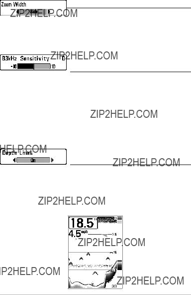
Zoom Width
Settings: Narrow, Medium, Wide; Default = Wide
Zoom Width adjusts the width of t he zoomed view on the Sona r Zoom View, which is on the left side of the display. See Views: Sonar Zoom View for more information.
83 kHz Sensitivity
(Advanced)
Settings:
83 kHz Sensitivity changes the sensitivity of the 83 kHz beam. Increasing the
83 kHz Sensitivity will display additional weak returns, and d ecreasing the 83 kHz Sensitivity will display fewer weak returns.
NOTE: 83 kHz Sensitivity is particularly useful for adjusting the sensitivity of the 83 kHz sonar returns in the 200/83kHz Split Sonar View. The 83kHz sensitivity can be adjusted without affecting the sensitivity of the 200 kHz re turns shown in the 200 kHz sonar window.
Depth Lines
(Advanced)
Settings: Off, On; Default = On
Depth Lines divide the display into four equal sections which are separated by three horizontal depth lines. The depth of each lin e is displayed along the depth scale. You can turn Depth Lines On or Off.
Depth Lines
 Depth Lines

 Noise Filter
(Advanced)
Settings: Off, L ow, Medium, High1, High2 , H igh3;
Default = Low
Noise Filter adjusts the s onar Noise Filter t o limit in terference on the display from sources such as your boat engine, turbulence, or other sonar devices.
The Off se tting removes all filtering. Low , Medium, and High1, High2, High3 settings add progressive filtering of the sonar returns. High1, High2, and High3 are useful when there is excessive trolling motor noise, but in some deep water situations, the High settings may actually hinder your unit???s ability to find the bottom.
Max Depth
(Advanced)
Settings: AUTO, 10 to 1000 ft, 3 to 330 m [International
Models only]; Default = AUTO
Max Depth controls the maximum depth of operation. When Max Depth is set to Auto, the Fish finder w ill acquire bo ttom readings a s needed (w ithin the capacity of the unit). When Max Depth is set to match your fishing maximum depth, your Fishfinder will not attempt to acquire sonar data below that depth, so more detail will be shown on the screen.
NOTE: If the bottom is deeper than the Max Depth setting,the digital depth readout will flash, indicating that the Fishfinder cannot locate the bottom.
Water Type
(Advanced)
Settings: Fresh, Salt (shallow), Salt (deep); Default = Fresh
Water Type configures your unit for operation in fresh or sa lt water. In salt water, you can also choose the shallow or deep setting.
Water Type affects the accuracy of deep water dep th readings. In salt water, what would be cons idered a large fis h might be 2 to 10 times bigger than a large fish in fresh water (depending on the type of fish yo u are seeking). The salt water setting allows for a greater range in fish size adjustment to account for this difference.
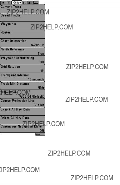
Navigation Menu Tab
Press the MENU key twice to access the Ma in
Menu, then press the RIGHT Cursor key until the
Navigation tab is selected.
NOTE: Menu options will vary depending on system settings, such as whether you are currently navigating.
NOTE: Menu options can be expanded or simplified by setting the User Mode to Advanced or Normal. See
Main Menu: User Mode for details.
Navigation Menu

Current Track
Settings: Save, Clear, Appearance
Current Track allows you to view the Current Track submenu. See Introduction to Navigation: Save or Clear a Current track for more information.
The Current Track Submenu contains the following menu options:
Save allows you to save the current track.
Clear allows you to delete the current track.
Appearance allows you t o c hange the style a nd color of the current track. (Breadcrumb Trail, Dashed Line, Solid Line or Wide Line, and if a line, choose a grayscale color).
Saved Tracks
Settings: Edit, Delete, Default
Saved Tracks allows you view the Saved Tracks submenu. See Introduction to Navigation: Edit, Delete, or Hide Saved Tracks for more information.
The Saved Tracks Submenu contains the following menu options:
Edit allows you to select a saved track and change its Name, Visibility (hidden or visible), Style, and Color (for track line styles only).
Delete allows you to delete a track from the saved tracks list.
Default sets the default appearance of your tracks, inclu ding Visibility (hidden or visible), Style, and Color (for track line styles only).
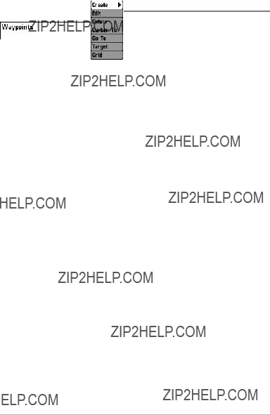
Waypoints
Settings: Create, Edit, Delete, Cursor To, Go To,
Target, Grid
Waypoints allows you to view the Way points submenu. See Introduction to Navigation for more information.
The Waypoints Submenu contains the following menu options:
Create allows y ou t o creat e a new way point, name it , and edit it immediately. The current boat position will be used as the default, but you can set the coordi nates to a ny valid po sition. The ico n used to represent th e w aypoint in th e Ch art an d C ombo Views can also be changed.
Edit allows you to choose from the saved waypoints list, and then edit the Name and Pos ition (Latitude and Longitude), as well as assign an Icon to represent the waypoint in the Chart and Combo Views.
Delete allows you to delete a waypoint from the saved waypoints list.
Cursor To allows you to move the cursor quickly to a waypoint from the saved waypoints list.
Go To allows you to select a waypoint and start navigation toward that waypoint or add that waypoint to the end of the current route.
Target allows you to apply a ta rget to a waypoint selected from the saved waypoints list.
Grid allows you to apply a trolling grid to a waypoint selected from the saved waypoints list.
NOTE: Only one waypoint can have either a target or a grid applied to it at one time. If you apply a target or a grid to a new waypoint, the originalwaypoint will lose its target or grid.
NOTE: The spacing of the rings on the waypoint targetand thespacing of the gridlines on the trolling grid is the same as the length of the scale bar on the left edge of the display. Zooming in or out will decrease or increase the spacing, respectively.
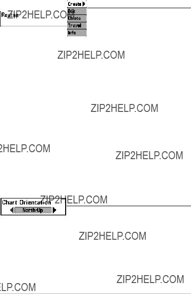
Routes
Settings: Create, Edit, Delete, Travel, Info
Routes allows you to view the Routes submenu. See Introduction to Navigation: Save, Edit, or Delete a Route for more information.
The Routes Submenu contains the following menu options:
Create allows you to create a new route from an empty route, name it, and add saved w aypoints to it immediately. You can also change the waypoint order of the route from this menu.
Edit allows you t o select a s aved route and change its nam e and the waypoints in it.
Delete allows you to delete a route from the saved routes list.
Travel allows you to choose a route from the saved routes list and use it as your current route. Routes can be traveled in either the forward or reverse direction . When y ou s elect a route, navigation begins immediately.
Info provides information about the route you choose from the saved routes list, including the distance and bearing from each wa ypoint to the next.
Chart Orientation
Settings:
Chart Orientation allows you to select w hether the Chart and Combo Views should be drawn
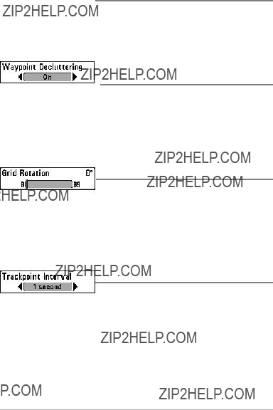
 North Reference
Settings: True, Magnetic; Default = True
North Reference allows you t o have bearings displayed wit h one of two orientations: True North or Magnetic North.
Waypoint Decluttering
(Advanced)
Settings: On, Off; Default = On
Waypoint Decluttering allows you to set the declutter feature On or Off. When two or more waypoints overlap, or are displayed close together on a chart view, the screen will automatically
Grid Rotation
Settings: 0?? to 89??, Default = 0??
Grid Rotation allows you to s et the orientation o f the trolling grid in degrees, where a setting of 0?? displays a standard North, South, East, West alignment. See Introduction to Navigation: Add a Waypo int Target or Trolling Grid for information.
NOTE: This fea ture may appear as ei ther Trolling Grid Rotation or Grid Rotation, depending on your model.
Trackpoint Interval
Settings: 1 second, 5 seconds, 10 seconds, 15 seconds, 30 seconds, or 60 seconds; Default = 1 second
Trackpoint Interval allows you to select the time period between trackpoints. The current track can only contain up to 20,0 00 t rackpoints, so longer time periods cause the track to extend back further in time, but will be less detailed.
Trackpoint Int erval work s in conjunctio n with Track Min Distance. Both conditions must be met before a trackpoint is added to the current track. During slow travel or drift, setting both Trackpoint Interval and Track Min Distance to small values will allow you to increase the track resolution.

Track Min Distance
(Advanced)
Settings: 1 to 300 ft, or 1 to 100 m [International Units only]; Default = 16 ft, 5 m
Track M in Distance allows you to s et a minimum d istance of travel before a trackpoint is added to the track.
Track Mi n D istance works in conju nction wit h Tra ckpoint Inter val. Both conditions must be met before a trackpoint is added to the current track. During slow travel or drift, setting both Trackpoint Interval and Track Min Distance to small values will allow you to increase the track resolution.
 Map Datum
(Advanced)
Settings: Various, Default = WGS 84
Map Dat um allows y ou t o change the map co ordinate system used by the Fishfinder to match those of a paper map.
 Course Projection Line
Settings: Hidden, Visible; Default = Visible
Course Projection Line allows you to display or hide an arow extending from the bow of the boat that projects your current course, and shows where the boat wil go if you continue on your present course.
Export All Nav Data
Settings: Follow screen instructions to activate.
Export A ll Nav Da ta allows you t o exp ort a ll saved Tracks, Waypoints, and Routes to an MMC/SD card. If an MMC card isn???t installed, an error message will be di splayed. Insert the MMC card and tr y a gain. See Introduction to Navigation for more information.

Delete All Nav Data
(Advanced)
Settings: Follow screen instructions to activate.
This menu option should be used with caution!
Delete All Nav Dat a allows y ou to delete all saved Tr acks, Waypoints, and Routes.
Continuous Navigation Mode
Settings: Off, On, Default = Off
Continuous Nav igation Mode allows you to co ntinue to n avigate and fish around a particular waypoint, even if you pass over it multiple times.
Chart Menu Tab
Press the MENU key twice to access the Ma in Menu and then press the RIGHT Cursor key until the Chart tab is selected.
NOTE: Menu options can be expanded or simplified by setting the User Mode to Advanced or Normal. See
Main Menu: User Mode for details.
Chart Menu
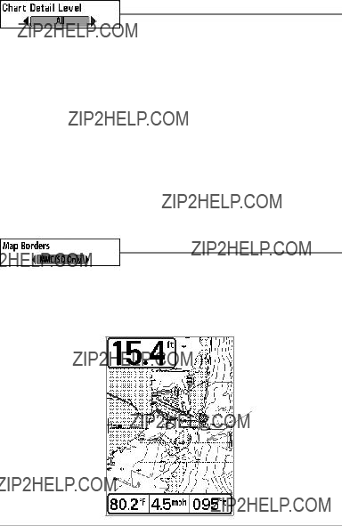
Chart Detail Level
Settings: Basic, Navigation, Underwater, All; Default = All
Chart Detail Le vel allows you t o s elect ho w much ch art detail y ou want displayed on the Navigation Views.
NOTE: Some chart details are only available with
Basic shows land areas, ports, obstructions, and restricted areas.
Navigation shows navaids, landmarks, ferryways, and navigation routes in addition to the Basic information.
Underwater shows depth contours, fishing areas, underwater wrecks, tides and currents in addition to the Basic and Navigation information.
All shows roads, buildings, railways, and other notations in addition to the Basic, Navigation, and Underwater information.
Map Borders
Settings: Hidden, M MC/SD O nly, Al l Vi sible;
Default = MMC/SD Only
Map Borders allows you to display or hide map borders. The dotted lines of a Map Border indicate an area which contains a different map.
Map Borders
Map
Borders
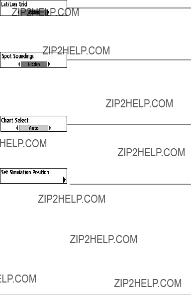
Lat/Lon Grid
Settings: Hidden, Visible; Default = Hidden
Lat/Lon Grid allows you to display or hide a gridshowing latitude and longitude lines.
Spot Soundings
Settings: Hidden, Visible; Default = Hidden
Spot Soundings allows you to display or hide spot soundings, which are depth measurements shown on the chart.
NOTE: Spot Soundings are only available with
Chart Select
Settings: Various, Default = Auto
Chart Select allows you to choose which chart to use if you have
Set Simulation Position
(Advanced)
Settings: Follow screen instructions to activate.
Set Simulation Position allows you to set the p osition of the boat used in the Simulator. Press any arrow on the 4- WAY Cursor C ontrol key to ac tivate the cursor a nd move it to the coor dinates where yo u wan t sta rt the simulation. Then confirm the position using the Set Simulation menu setting.
NOTE: The cursor must be active in order for this procedureto work. If the cursor was not active before you began this procedure, an error message will appear. Exit the menu, set the cursor, then try again.

Set Map Offset
(Advanced)
Settings: Follow screen instructions to activate.
Set Map Offset allows you to change the map offset used by your Fishfinder. Press the
The Map Offset will be applied to all map s and not just the map that requires the correction. The Map Offset should be cleared if a different map is to be used.
NOTE: The cursor must be active in order for this procedure to work.If the cursorwas not active before you began this procedure, an error message will appear. Exit the menu, set the cursor, then try again.
Clear Map Offset
(Advanced)
Settings: Follow screen instructions to activate.
Clear Map Offset allows you t o clear t he Map Offset. The Clear Map Offset menu option is available when Map Offset is active.

Setup Menu Tab
From a ny vie w, press th e M ENU ke y tw ice to access the tabbed Main Menu, then press the RIGHT Cursor key until the Setup tab is selected.
NOTE: Menu options will vary depending on which accessories are attached to the unit.
NOTE: Menu options can be expanded or simplified by setting the User Mode to Advanced or Normal. See
Main Menu: User Mode for details.
Setup Menu

Units - Depth
Settings: D omestic Models: Feet, Fathoms; International
Models: Meters; Default = Feet/Meters
Units - Depth selects the units of measure for all
Units - Temp
(International only)
Settings: Celsius, Fahrenheit; Default = Celsius
Units - Temp selects the units of measure for all
International Models only.
Units - Distance
Settings: Domestic Models: Statute Miles , Nautical Miles,
Default = S tatute Mi les; International Mode ls:
Meters/Kilometers, Meter s/Nautical Mi les, Feet/Statute
Miles, Feet/Nautical Miles, Default = Meters/Kilometers
Units - Distance selects the units of measure for all
Units - Speed
Settings: Domestic Models: mph, kts; International Models: kph; Default = mph/kph
Units - Speed selects the units of measure for

User Mode
Settings: Normal, Advanced; Default = Normal
User Mode sets the menu system to Normal or Advanced. When set to Normal (default setting), the basic set of menu options are shown in the menu system. When set to Advanced, additional menu options are added to the menu system. See Main Menu: User Mode for details.
Language
(International only)
Settings: Various, Default = English
Language selects the display language for menus. International Models only.
Triplog Reset
Settings: Follow screen instructions to activate.
Triplog Reset resets the Triplog to zero, and w ill ap pear in the m enu if a Temp/Speed Accessory is connected and the paddlewheel has moved at least once, or if the GPS Receiver is connected.
The Triplog provides the following information: timer for elapsed time, distance traveled since last reset, and average speed.
NOTE: See Views to find out how to display Triplog information onthe screen.
Restore Defaults
Settings: Follow screen instructions to activate.
Use this menu choice with caution!
Restore Defaults resets ALL menu settings to their factory defaults.
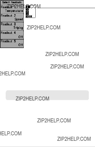
Select Readouts
The readout position on the screen is shown in the Select Readouts Window.
Select Readouts
(Advanced, Sonar View only)
Settings: Various, Default = Off
Select Readouts sets the information to display in e ach of th e 5 f
Data win dows ca n dis play reado uts from supported accessories such as GPS Receiver or
Temp/Speed. Each data window can be empty or co ntain one of the following information categories:
NOTE: The availability of the digital readout information corresponds with the view selected, the accessory attached, and whether or not you are navigating.

Depth Offset
(Advanced)
Settings:
Models only]; Default = 0
Depth Offset will adjust the digital depth readout to indicate depth from the waterline o r boat's keel. Ent er a pos itive vertical measurement from the transducer to t he waterline t o r ead t he d epth from the water line. Enter a negative vertical measurement from the tr ansducer to keel to read the depth from the keel.
Temp. Offset
(Advanced)
Settings:
Temp. Offset will adjust the temperature readout by the amount entered.
Speed Calibration
(Advanced, with Temp/Speed only)
Settings:
Speed Ca libration will adjust th e s peed readout by t he p ercentage entered, and will appear in the menu if a Temp/ Speed Accessory is connected and the paddlewheel has moved at least once.
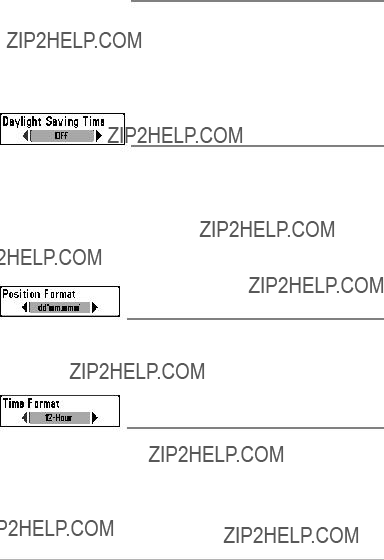
 Local Time Zone
(Advanced)
Settings: Various, Default = EST
Standard Time
Local Time Zone selects your time zone in reference to the time reported by the
GPS receiver when Time+Date is selected as a Digita l Readout on the So nar View (see Setup Menu Tab: Select Readouts).
Daylight Saving Time
(Advanced)
Settings: Off, On; Default = Off
Daylight Saving Time adjusts th e t ime d isplay to a ccount for loc al Daylight Saving Time when Time+Date is selected as a Digital Readout on the Sona r View (see Setup Menu Tab: Select Readouts).
Selecting O n adds one hour to the t ime display ad justed for your local time zone. Selecting Off leaves the time display as adjusted for your local time zone.
Position Format
(Advanced)
Settings: dd.ddddd??, dd??mm.mmm', or d d??mm'ss";
Default = dd??mm.mmm'
Position Format selects the format of thelatitude andlongitude position display.
Time Format
(Advanced, International only)
Settings: 12 hour, 24 hour; Default = 12 hour
Time Format changes the time format used by the unit. Time Format selects a 12 hour or 24 hour f ormat for the time of day displayed when Time + Date is selected as a Digital Readout on the Sonar View (see Setup Menu Tab: Select Readouts).
Date Format
(Advanced, International only)
Settings: mm/dd/yy,dd.mm.yy,yy.mm.dd; Default = mm/dd/yy
Date Format changes the date format used by the unit. Date Format selects the format for the date display when Time + Date is selected a s a Digital Readout on the Sonar View (see Setup Menu Tab: Select Readouts).
 NMEA Output
(Advanced)
Settings: Off, On; Default = Off
NMEA Output turns the N MEA* out put on o r off. NMEA Output should be turned On if you connect the NMEA Output wires of the GPS Receiver cable to another
*NMEA 0183 is a N ational M arine El ectronics Asso ciation s tandard fo r dat a communication.
NOTE: A separate purchase of accessory
The following NMEA sentences are output when NMEA Output is turned On:
DPT - Depth
MTW - Water Temperature
GLL - Lat/Lon Position
GGA - GPS Fix Data
RMC - Recommended Minimum Specific GNSS Data
VTG - Course Over Ground and Ground Speed
ZDA - Time and Date
When n avigating, the f ollowing NM EA sent ences are also out put wh en NMEA Output is turned On:
APB - Autopilot Sentence B
BWR - Bearing and Distance to Waypoint
RMB - Recommended Minimum Navigation Info

Sonar
Settings: Off, On; Default = Off
Sonar sets whether the Sonar views are shown in the View rotation. Select Off to deactivate Sonar and remove the Sonar Views from the View rotation.
Screen Snapshot
Settings: Off, On; Default = Off
Screen S napshot activates the sc reen snapshot funct ion. When Screen
Snapshot is enabled, pressing the MARK key creates a saved screen capture on the
NOTE: For more information, see Snapshot and Recording View and Snapshot and Recording
NOTE: You must have an
NOTE: If yo u u se y our MMC/SD c ard i n two different Fishfinder units that ha ve different screen sizes, the recordings made on one unit will still be presenton the card, but will be represented by the Unavailable icon (circle with a slanted line hrought it) on the Snapshot and Recording View on the other unit.

Views Menu Tab
From any v iew, pre ss the ME NU ke y twic e t o access the tabbed Ma in Me nu, then p ress t he RIGHT Cursor key until the Views tab is selected.
This m enu tab allows you to set th e available views to hidden or visible in the view rotation. The view will be removed from the view rotation if it is set to Hidden and will be displayed in the view rotation if it is set to Visible.
NOTE: See Views for more information.
Views Menu
Troubleshooting
Before contacting the Humminbird?? Customer Resource Center, please read the following section. Taking the time to review these tro ubleshooting guidelines may allow you to s olve a performance pro blem yourself, and therefore avoid sending your unit back for repair.
Fishfinder Doesn???t Power Up
If your Fishfinder doesn???t power up, use the Installation Guide that also comes with it for specific confirmation details, making sure that:
???The power cable is properly connected to the Fishfinder control head.
???The power cable is wired correctly, with red to positive battery terminal and black to negative terminal or ground.
???The fuse is operational.
???The battery voltage of the power connector is at least 10 Volts.
Correct a ny k nown problems, including removing corrosion from th e battery terminals or wiring, or actually replacing the battery if necessary.
Fishfinder Defaults to Simulator with a Transducer Attached
A connected and f unctioning tra nsducer w ill c ause the new
detecting the transducer. Perform the following troubleshooting tasks:
???Using the Installation Guide that also comes with your Fishfinder, check to make sure tha t the transducer ca ble is securely connected to the
Fishfinder. Reconnect if n ecessary, and power up the Fishfinder again to see if this fixes the problem.
???Replace the
???Check the tr ansducer cable. Replace th e tra nsducer if t he ca ble is damaged or corroded.

Display Problems
There are several main conditions or sources of possible interference that may cause problems w ith the quality of t he in formation displayed on the control head. Look in the following table for some symptoms of display problems and possible solutions:
The control head loses If the power output of your boat???s engine is unregulated, power at high speeds. the co ntrol hea d ma y b e prot ecting i tself u sing i ts
voltage does not exceed 20 Volts.
When the boat moves at higher speeds, the bottom disappears or suddenly weakens, or the display contains gaps.
The transducer position may need to be adjusted. A mix of air and water flowing around the tr ansducer (cavitation) may be interfering with the interpretation of sonar data. See your Installation Guide for suggestions on adjusting the transducer position.
Electrical noise from the boat???s engine may be interfering with sonar reception. See Finding the Cause of Noise for more information.
There are no fish detected, even when you know they are in the water under the boat, or sonar readings seem weak or faulty.
Sonar readings may be affected if the transducer is not positioned correctly (i.e. mounted at an angle, not straight down), or there is some kind of mechanical interference, either because it is mounted inside a hull that is too thick for p roper son ar transmission, the bond betwe en th e transducer a nd the hull is not a irtight, or because the transducer is dirty. Check with your Installation Guide for guidance on
Low battery voltage may be affecting the power of signal transmission.
Electrical noise from the boat???s engine may be interfering with sonar reception. See Finding the Cause of Noise for more information.

Finding the Cause of Noise
Electrical noise usually affects the display with many black dots at high speeds, and high sensitivity readings. One or more of the following sources can cause noise or interference:
Cavitation from the boat???s propeller
Turbulence created by the pr opeller can cause noise; m ake sure t he tr ansducer i s mo unted at least 15??? (38 cm) from the propeller, and that the water flows smoothly over the face of the transducer at all times.

300 Series??? Fishfinder Accessories
Accessories customize the Humminbird?? Fishfinder to your needs and enable you to stay on the edge of new technology. When an accessory is connected to the Hum minbird?? F ishfinder, additional menus and readouts are added automatically to the Main Menu Syst em. Accessories available today that a re supported by your Humminbird?? include:
Temperature/Speed: Simply plugs into the H umminbird?? c ontrol head a nd provides real t ime speed and t emperature read outs, a s well a s a v aluable Triplog function.
NOTE: If an external Temperature/Speed
Be sure to check out our web sit e www.humminbird.com for additional new and exciting accessories to grow your Humminbird?? Fishfinder!

Specifications
Depth Capability. . . . . . . . . . . . . . . . . . . . . . . . . . . . . . . . . . 1000 ft (330 m)
Power Output . . . . . . . . . . . . . . . . . . . . . . . . . . . . . . . . . . 300 Watts (RMS),
2400 Watts (Peak to Peak)
Operating Frequency. . . . . . . . . . . . 200 kHz and 83 kHz (DualBeam Plus???)
Area of Coverage . . . . . . . . . . . . DualBeam Plus???: 60?? @
Target Separation . . . . . . . . . . . . . . . . . . . . . . . . . . 2 1/2 Inches (63.5 mm)
Power Requirement . . . . . . . . . . . . . . . . . . . . . . . . . . . . . . . . . . .
LCD Matrix. . . . . . . . . . . . . . . . . . . . . . . . . . . . . . . . . . . . . . . . 320 V x 240 H
Transducer . . . . . . . . . . . . . . . . . . . . . . . . . . . . . . . . . . . . . . . . . . XNT 9 20 T
Transducer Cable Length . . . . . . . . . . . . . . . . . . . . . . . . . . . . . . . 20 ft (6 m)
Current Draw . . . . . . . . . . . . . . . . . . . . . . . . . . . . . . . . . . . . . . . . . . . 350 mA
IPX Rating . . . . . . . . . IP67 Waterproof/Submersible @ 1 m for 30 minutes and dust tight
NOTE: Humminbird?? verifies maximum stated depth in saltwater conditions,but actual depth performance may vary due to transducer installation, water type, thermal layers, bottom composition and slope.
NOTE: Product specifications and features are subject to change without notice.

Glossary
Sonar Terms:
Beam (Sonar Beam) The wide,
Bottom Contour The profile of the bottom graphed to the display as thedepth changes.
Bottom Hardness The density (or composition) of the bottom. Varying levelsof hardness can be determined by interpreting the ???thickness??? of the main sonar return. Hard returns appear thin and black, softer returns appear thicker and less black. It is important to note that a sonar return from a sloping bottom can have the appearance of a softer bottom.
Cavitation The effect of air bubbles created as the propeller rotates and the boat moves through the water.
Cone Angle The angular measurement of the sonar beam at a specific dB down point (i.e.
Dead Zone The area of the sonar beam that receives the sonar signal after the main bottom return. Fish and other objects close to the bottom that fall within the dead zonewill probably not be visible in the sonar beam. Precision sonar beams, such as the Humminbird?? 20?? beam, have a smaller dead zone than wider sonar beams.
Decibel The measurement for sound pressure level, or ???intensity???of the sonar return.See
dB Down Point.
dB Down Point The standard decibel level at which the sonar cone angle is measured, and is written as ???@
Display,FSTN (Film
Frequency A measure ofthe number of sound wave cycles per second of a soundimpulse transmitted underwater. A typical frequency for fishfinders is 200 kHz, which offers a good balance of performance under many conditions. Lower frequencies, such as 50 kHz, are capable of penetrating to greater depths, but with less resolution. Higher frequencies, such as 455 kHz, offer greater resolution, but are limited in depth performance. Humminbird?? uses a variety of frequencies that are optimized for specific applications.

Grayscale The use of varying shades of gray to represent the strength of the sonar signal on the display. Traditionally, the strongest sonar signals a re represented in black, and progressively weaker signals are represented in progressively lighter shades of gray.
Noise The unintentional, external sound waves that interfere with the optimal operation of sonar. Noise appears as random ???dots??? on the d isplay and is caused by a varie ty of sources. Many Humminbird?? products have a Noise Filter menu setting that allows the user to clear the screen ofnoise that is difficult to eliminate(also, see Troubleshooting).
Pixels The ???picture elements???, or small square blocks, that make up the image onthe LCD. Measured as a v ertical by horizontal number (i.e. 6 40V x 32 0H), this k ey specification typically indicates t he quality of r esolution. In fishfinders, the total resolution (vertical multipliedby horizontal) is often less important than the ???Vertical Pixel??? resolution because a greater number of vertical pixels provide finer resolution of targets detected by sonar. Sonar informationon the horizontal axiscan vary greatly, depending on boat speed and the Chart Speed setting.
Power Output The amount of sound energy emitted into the water by the transducer???s transmitter. Poweroutput is measuredusing either RMS (Root Mean Square) or
Pulse Width (Pulse Length) The length of time that a sonar sound burst is transmitted into the water.Shorter pulse widths provide better target separation, but cannot travel to great depths. Longer pulse widths provide better depth penetration, but result in poorer target separation.Humminbird?? varies pulse width based on depth to optimize both target separation and depth performance. See TargetSeparation.
Second Return Describes the appearance of a second sonar return below the primary sonar return (bottomcontour) at exactly twice the true depth. The second return is caused by the same sonar energy bouncing off the bottom once, rebounding to the water surface and then travelingback down to the bottom to be reflected again. Second returns are more common in shallow water and over hard bottoms; it is possible to see a third sonar return under some circum stances. The sec ond return provide s use ful info rmation to help determine bottom hardness, as areas with harder bottoms will generally create a second return. The second eturnr can beused as a guide to set Sensitivity when in shallower water.
SONAR (SOund and NAvigation Ranging) Sonar technology uses precision sound bursts transmitted underwater to determine the distance and other attributes of objects in the water. Distance can be determined because the speed of sound in water is constant, and the time for the s ignal to r eturn i s me asured. So und also travels v ery q uickly underwater, makingsonar a responsive,
Sonar Update Ra te The num ber of times per second that the transducer???s transmitter/receiversends and receives sonar signals. A very fast sonar updateratecollects more informationand provides a more detailed image of the b ottom, fish, and structure. Many Humminbird?? units operate at up to 40 times per second when in single frequency operation. Due to the limitation ofthe speed of sound in water, the update rate begins to slow as depth increases to deeper than 50 feet. In very shallow water (less than 10 feet), however, update rates as much as 60 times per second can be achieved.
Speed The rate at which the boat moves through the water. Boat speed can be measured as Speed Over Ground orSpeed Through Water. Speed Over Ground is provided by GPS, and is the measurement of the boats progress across a given distance. Speed Through Wateris provided by a speed paddlewheel, and is the measurement of the flow past the boat, which may vary depending on current speed and direction. Speed Through Water is most critical for anglers using downriggers, as it impactsthe running depth of the down riggers. Speed Over Ground is optimal for navigation, as accurate destination times can be derived from this measurement. Humminbird?? products allow for input and display of both sources.
Structure A general term for objects on the bottom that present a discontinuity andare a likely attractor for fish. This includes bottom contour features
Surface Clutter A phenomenon where sonar returns are reflected off of tiny objects near the s urface of the water , inc luding alg ae and eve n air bubb les. Typically, saltwater environments have significantly greater surface clutter than freshwater due to continuous wind and wave action that causes aeration at the surface.
Target Separation The measurement of minimum distance that a fishfinder needs to be able to recognize two very close objects as two distinct targets (i.e. two fish hanging very close, or a fish hanging very clos e to structure). Humminbird?? fishfinders provide a v ery good 2 1 /2 inches of ta rget s eparation in shallower than 100 f eet of depth. Target separation decreasesas depth increases due to the need for longer Pulse Width to achieve greater depth. See Pulse Width.

Thermoclines Water layer(s) of disti nctly di fferent temperatures that c reate a sonar reflection due tothe densityof the differing water temperatures. Typically a thermocline will appear as a continuous band crossa thedisplay at somedistanceabove the bottom contour. Thermoclines are of interest to angler s b ecause fish will su spend ab ove or b elow the thermocline as theyseek the optimum temperature and oxygen levels.
Time VariableGain (TVG) A processing step applied to the sonar return to ???normalize??? the data so that objects of equal size (i.e. fish) appear to be the same size, even if they are separated by a good distance.
Transducer The transducer is part of the sonar system, which mounts on the boat and is in contact with the water, that con verts the electrical energy from the transmitter into sound energy, andthat forms the sonar beam in turn. Internaly, the transducer consists of one or more piezo electric disks that expand by very minute amounts to create the sound wave. This elementalso works in reverse, converting the returned soundenergy back into an electrical signal that the receiver interprets. See SONAR.
Zoom A f eature t hat foc uses on a smaller are a of the b ottom to p rovide enhanced resolution. With enha nced resolution, the ang ler can mo re easi ly see fish hanging in structure or multiple fish hanging close together.
Zoom, Bottom Lock Bottom Lock Zoom is a feature that focuses on a smaller area just above the bottom to provide enhanced resolution. Unlike regular zo om, it continuously graphs the bottom at a constant point on the display regardless of changes in depth. This ???flattens??? out the bottom contour, but is effective at showing fish on or near the bottom, and is preferred bymany saltwater anglers.

GPS & Navigation Terms:
Acquisition Time The length of time that a GPS receiver typically takes to determine a position from at lea st three satelli tes. Hu mminbird?? GPS rece ivers p rovide ver y fast acquisition times (underone minute), permitting users to get out on the water faster.
Altitude The height measurement above sea level. Altitude is a measurement that can be provided by GPS.
Bearing (BRG) The direction to a destination waypoint measured in degrees from North (i.e. 321??, where 000?? is North, 090?? East, 180?? is South, 270?? is West).
Chartplotter A navigation device that shows Present Position on a M ap, along with Tracks, Waypoints,and Routes. All Chartplotters are also considered Trackplotters.
Cold Start The procedure that a GPS r eceiver must perform when it d oes not have historical information egardingr its current location. This procedure typically lasts for several minutes, and may be experienced upon first power up of the receiver, or if the receiver has been moved a great distance.
Course Over Ground (COG) The current direction the boat is traveling measured in degrees from North (i.e. 321??, where 000??is North, 090?? East, 180?? is South, 270?? is West). When the Course Over Ground is equal toBearing, the boat is said to be ???On Course??? and will arrive at the dest ination in the most efficient manner. COG is o ften confused with Heading. See Heading.
Cross Track Error (XTE) The
Track.
DifferentialGPS (DGP S) A system used to improve the p osition ac curacy of the Department of Defense GPS through the use of secondary ???correction signals??? broadcast from ground stations around the coastal United States and on some inland waterways. These correction signals are provided by the USCG and received by an auxiliary Differential Beacon Receiver (DBR) that connects to the GPS receiver. The advent of WAAS has largely negated the need for the added expense of a DBR in the United States.
Distance ToGo The
to Go and Speed Over Ground.

Estimated Position Er ror (EPE) A calculation that i ndicates th e p otential p osition inaccuracy the usermay experience due to a variety of GPS factors which include satellite position in the sky, signal strength, and others factors.
Fix Type Indicates whether the GPS receiver is providing 2D fix or 3D fix. A 2Dfix requires only three satellitesand provides only latitude and longitude. A 3D fix requires four or more satellites, and provides latitude, longitude, and altitude.
GPS (Global Positioning System) GPS provides accurate position (latitude, longitude, altitude) information virtually a nywhere on th e earth through sa tellite technology and personal receiverson the ground. SeeHow GPS Works.
Heading The direction the boat is pointing and is measured in degrees (i.e. 321??, where 000?? is North, 090?? East, 180?? is South, 270?? is West). Due towind and waves, the boat is often traveling ina slightly different direction than it is heading, and therefore Heading is often confused with Course Over Ground. See Course Over Ground.
Map Datum Refers to a particular survey of the earth???s surface that was referenced when creating a chart (ie. . WGS84).It is important to select the corect Map Datum setting in your fishfinder when c omparing GPS posi tion to a pape r cha rt to a void slight positio n inaccuracies. Almost all electronic charts use the WGS84 Map Datum and therefore, they do not require setting changes.
MMC (Multi Media Card) An MMC is a postage
North, Magnetic The pr inciple reference po int of the co mpass (i.e . Nor th is 0 00??). Magnetic North relies on the ea rth???s magnetic field to align a metal pointer generally towards True North. However, due to localvariations in the earth???s magneticfield around the globe, the difference between True Northand Magnetic North can be greater than10??. See True North.
North, True The principle reference point of the compass (i.e. North is 000??). True North uses the axis of the rotation of the earth as the reference for North and is constant for all points on the earth. Most GPS units default to True North as the setting. The GPS heading may vary from the boat compass heading because the compass uses Magnetic North. See
Magnetic North.

Present Position The c urrent location (l atitude, lo ngitude) de termined b y G PS. The Present Position is indicated
Route A series of waypoints linked together in a specific sequence to define a navigation path between two points, and saved in the fishfinder???s memory. Routes are often used when frequently traveling between two or more locations because it is a faster and more accurate method t han repeatedly selecting individual w aypoints each time one travels through the same area. Routes consist of a Start Waypoint, an End Waypoint, and a series of waypoints in between. Users can begin navigation at the beginning, the end(to run the route in reverse) or at any waypoint inbetween. See Waypoint.
SD (Secure Digital) An SD card is virtually identical in function to an MMC; however, the speed atwhich information can be accessed is generally faster, the storage capacity is generally larger, andhet card has security features which can be used to prevent extracting the data from the card. SD is the same format that many digital cameras use. See MMC.
Selective Availability (SA) A GPS system ???feature??? that can be implemented by the U.S. Department of Defense (DoD)to degradethe accuracy of GPS positioninginformation. With SA active, the GPS is accurate to within 100 meters 95% of the time. With SA inactive,the GPS is accurate to within 45 m eters 95% o f the time. Currently, SA is inactive and the consumer can enjoy the greater precision GPS p rovides; however, the DoD reserves the right to activate SA at any time.
Speed Over Ground (SOG) The measurement of the boat???s progress across a given distance and the speed measurement provided by GPS. An alternate, Speed Through Water, is provided by a speed paddlewheel, and is the measurement of the flow past the boat, which may vary depending on current speed and direction. Speed Over Ground is optimal for navigation because accurate destination times can be derived from this measurement. Humminbird?? products allow for input anddisplay of both speed measurements.
Time To Go (TTG) The estimated time required to reach the destination waypoint. TTG is calculated using the SOG and DTG. See SOG and DTG.
Track A series of saved points that define the past path of theboat. TheseTrack Points are saved at regular time intervals. Tracks are a useful and quick method to see where you???ve been, and an easy guide to follow to get you back to the starting point. Generally,all GPS units have a limited number of Track Points that can be saved before the unit runs out of memory and beginserasing the first trackpoints saved. Because of this, the user can adjust the Track Point Interval menu to increase the amount of time between when points are saved, and thus extend the distance covered by a track. Tracks can also be permanently saved to memory and

Track Line (TRK) The planned line of travel between two waypoints, and it represents the most efficient path between the two points because it is a s traight line. The TRK is measured in degrees (i.e. 321??, where 000?? is No rth, 090?? East, 180?? is South, 270?? is West). See Cross Track Error and Course Over Ground.
Trackplotter A navigation device that shows Present Position, along with Track,Waypoint, and Routes,but NO MAP in the background. See Chartplotter.
Trolling Grid A Humminbird?? feature that displays a pr ecise reference grid around a waypoint. This grid is used as aguide pattern for trolling around a specific area to assure a more efficient and complete coverage of that area.
UTC (Universal Time Constant) UTC is the ???standard time??? used in navigation and is the local time in Greenwich England. (UTCis equivalent toGreenwich Mean Time (GMT)).
WAAS (Wide Area Augmentation System) WAAS is complementary technology to GPS that provides enhanced accuracy through correction signals broadcast from Federal Aviation Administration WAAS satellites stationed over the USA. These secondary signals are automaticallyreceived by the standard Humminbird?? GPS Receiver. With WAAS signal, GPS accuracy is improved to within 3 meters 95% of the time. Outside the United States, regional governmental coalitions have created similar systems such as EGNOS (Europe) and MSAS (Japan).
Waypoint The saved location (latitude, longitude) of a point of interest that is storedin a GPS receiver???s memory. This can include a marker buoy, dock, fishing hole, or anywhere else the user may want to return to. Humminbird?? products offer the ability to name and assign a symbol to the saved location. Depth, Date, and Time of Day when the waypoint was created is also saved.
Waypoint Target A Humminbird?? feature that displays a precise ???bull???s eye??? around a selected waypoint. This bull???s eye is use d to easily monito r bo at position relative to a waypoint, and is useful for fishing over submerged structure. With Waypoint Targets,a quick look at the screen lets you know how far off the waypoint the boat has drifted.

Notes
117
Contact Humminbird??
Contact the Humminbird?? Customer Resource Center in any of the following ways:
By Telephone:
(Monday - Friday 8:00 a.m. to 4:30 p.m. Central Standard Time):
By
(typically we respond to your
cservice@johnsonoutdoors.com
For direct shipping, our address is:
Humminbird
Service Department
678 Humminbird Lane
Eufaula, AL 36027 USA
118