SAFETY INSTRUCTIONS 
FAILURE TO FOLLOW THESE SAFETY INSTRUCTIONS MAY RESULT IN
SERIOUS INJURY, PROPERTY DAMAGE AND WILL VOID WARRANTY.
Owner must ensure that all players know and follow these rules for safe operation of the system.
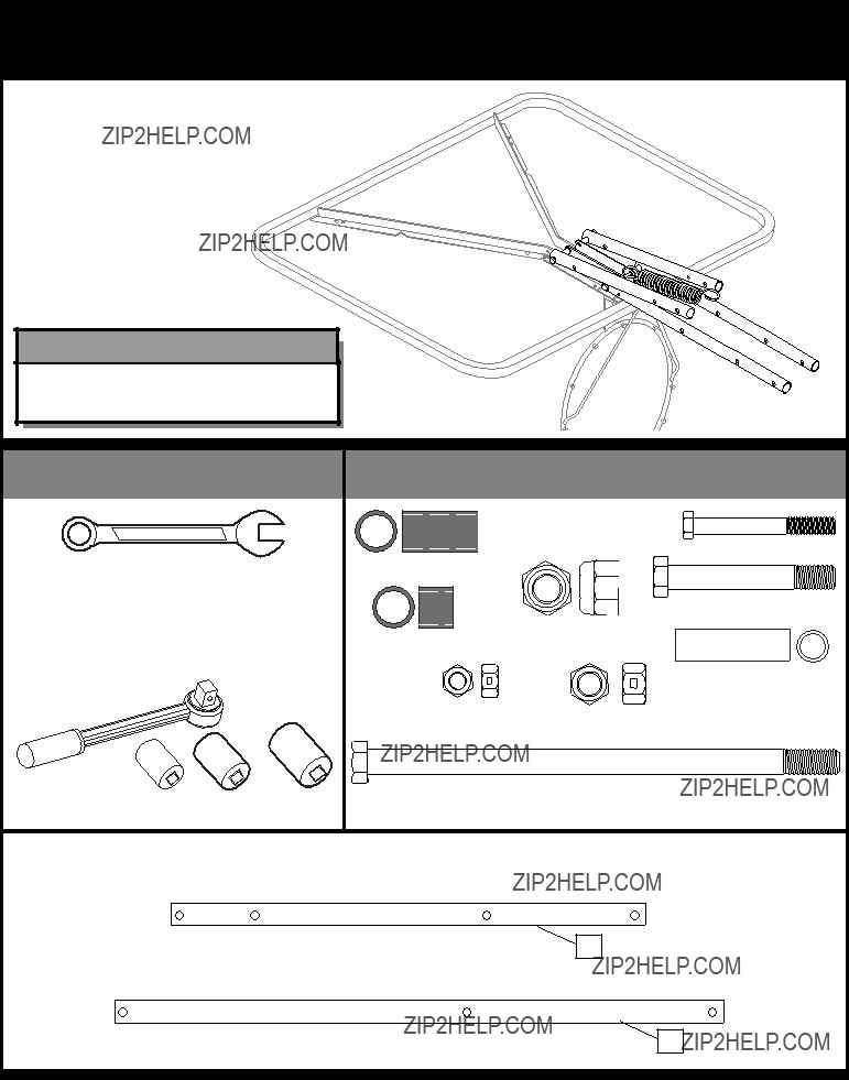
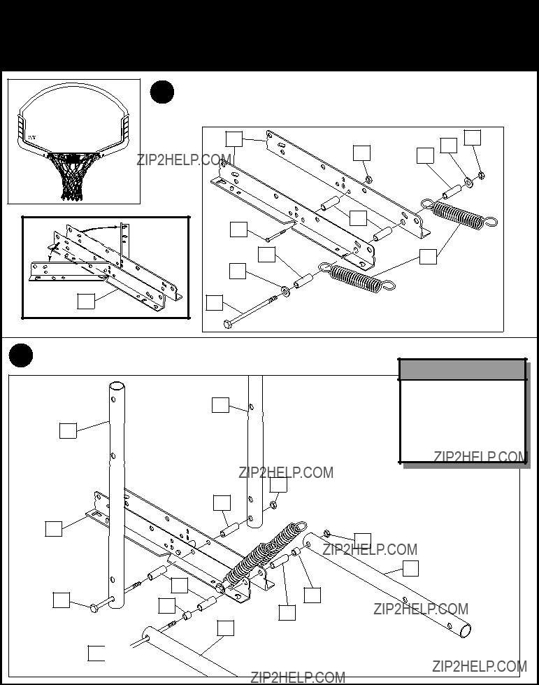
To ensure safety, do not attempt to assemble this system without following the instructions carefully. Proper and complete assembly, use and supervision is essential for proper operation and to reduce the risk of accident or injury. A high probability of serious injury exists if this system is not installed, maintained, and operated properly. Check entire box and inside all packing material for parts and/or additional instructional material. Before beginning assembly, read the instructions and identify parts using the hardware identifier and parts list in this document.
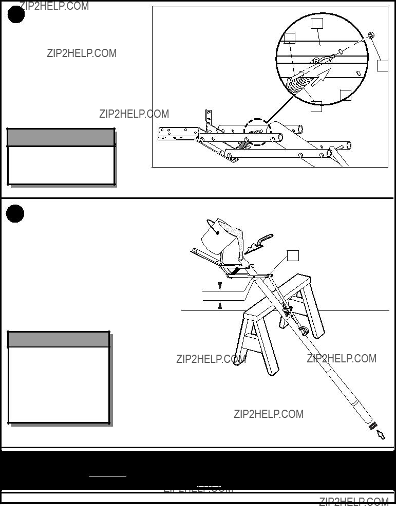
???If using a ladder during assembly, use extreme caution.
???Two (2) people are reccomended for this operation.
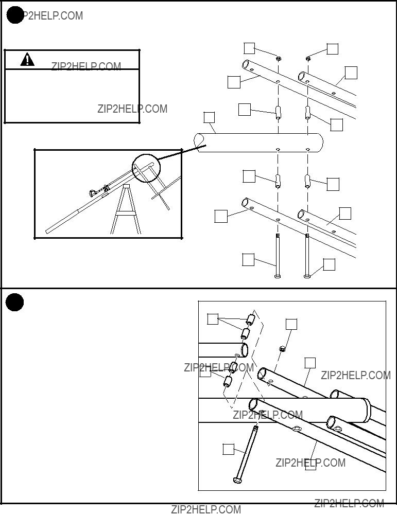
???Seat the pole sections properly. Failure to do so could allow the pole sections to separate during play.
???Before digging, contact utility company to locate underground power cables, gas, and water lines. Ensure there are no overhead power lines within 20 ft. (7 m) radius of pole location.
???Climate, corrosion, excessive use, or misuse could result in system failure.
???If technical assistance is required, contact Huffy Sports.
???Minimum operational height is 6'6" (1.98 m) to the bottom of backboard.
???This equipment is intended for home recreational use only and NOT excessive competitive play.
???Read and understand the warning label affixed to pole. Label is shown to the right.
???The life of your basketball pole depends on many conditions. The climate, placement of the pole, the location of the pole, exposure to corrosives such as pesticides, herbicides or salts are all important.
???Adult supervision is recommended when adjusting height.
???Serious injury could occur if teeth/face come in contact with backboard, net, or rim.
Most injuries are caused by misuse and/or not following instructions. Use caution when using this system.

 WARNING
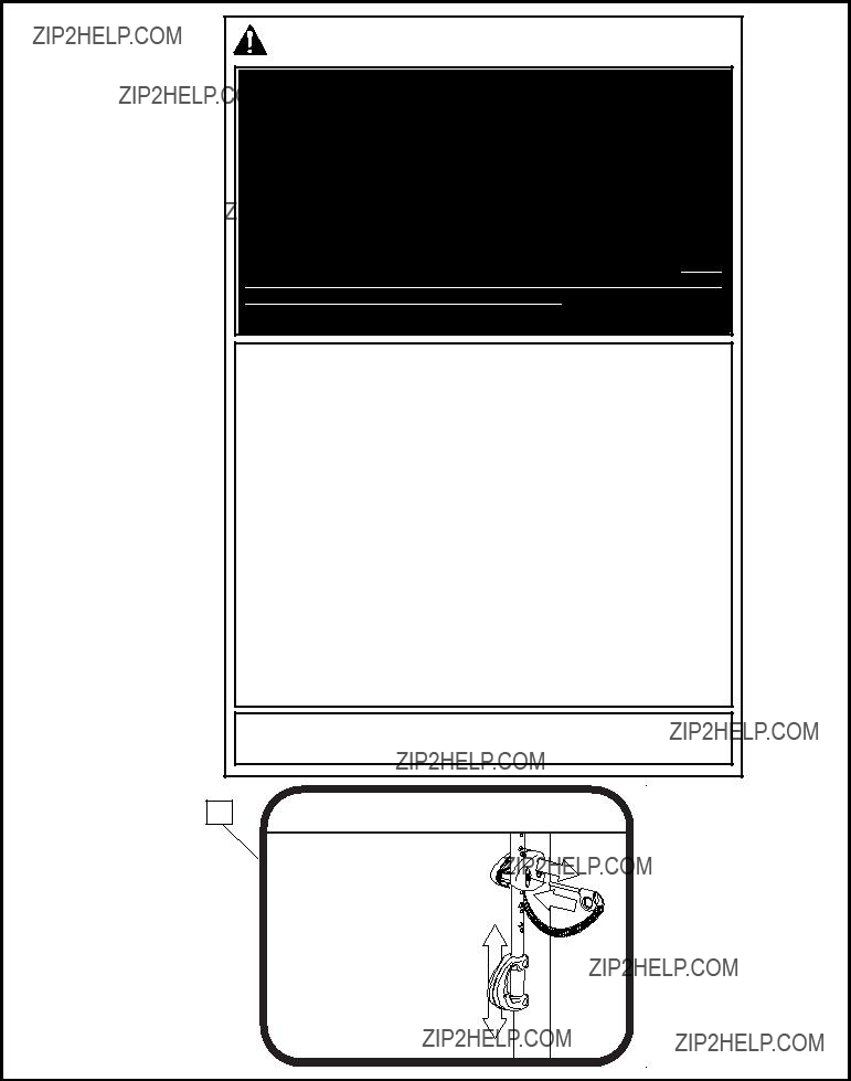


 WARNING!


 PLAYING SURFACE
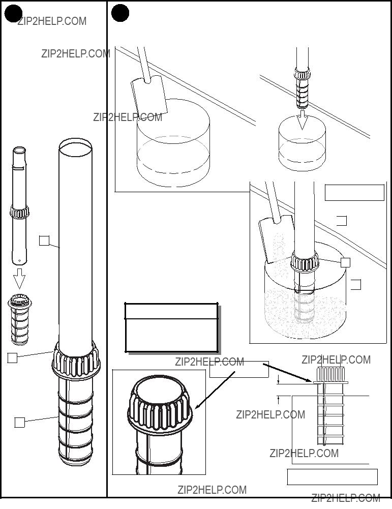
 3
3


 4
4


 Keep flange pushed down to concrete and leveled.
 5
5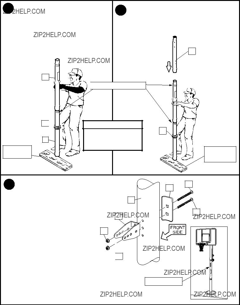


 Taped reference marks

 IMPORTANT!:
 9
9


 33
33


 WARNING!
 WARNING!
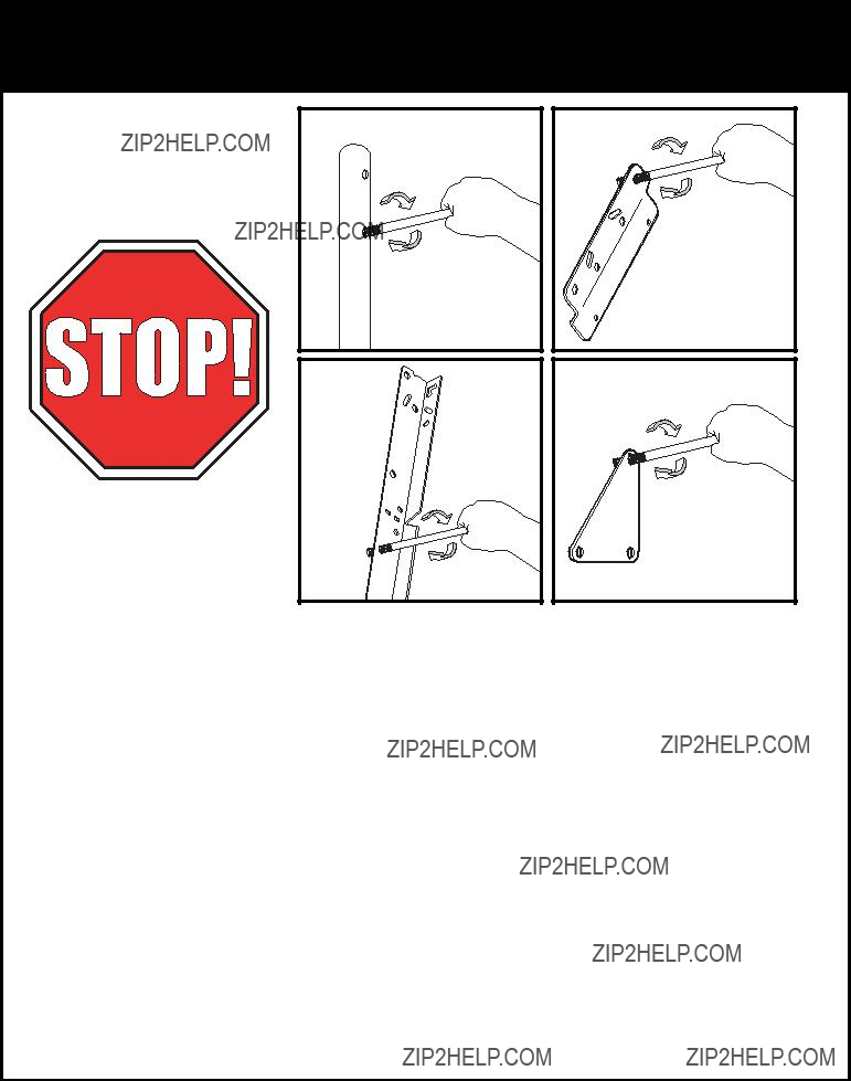
 CLIP ???ARM???
 CLIP ???BODY???
 NETCLIP
 WARNING
 WARNING
 WARNING
 WARNING!