SETTING THE WEEKDAY AND SINGLE DAY
ALARMS
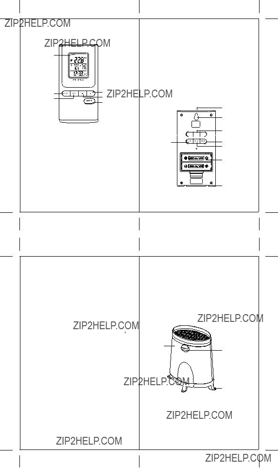
??Press ALARM button once to enter into the alarms setting mode. The default alarm is a Weekday alarm.
The abbreviation ??OFF?? with a letter ??
 W ?? next to it will be displayed, if the alarm has not been set previously.
??Press and hold the ALARM button for two seconds. The hour digit will flash.
??Enter the hour using back panel UP ( ) or DOWN (
  ).
).
??Press the ALARM again. The minute digits will flash.
??Enter the minutes using UP (  ) or DOWN (
  ).
).
??Press the ALARM button again to confirm and the weekday alarm time will be set.
??Set Single day alarm if desired in the same manner.
SETTING THE ICE WARNING ALARM
If Weekday or Single day alarm is set, the Ice Warning Alarm can be programmed.
??Press the back panel ALARM button once to enter into the Ice Warning Alarm setting mode. The abbreviation ??OFF?? with a ??PRE-AL?? next to it will be displayed.
??Press and hold the back panel ALARM button for two seconds. The ??30?? number will flash, meaning that if selected, the alarm will sound 30 minutes earlier than the Weekday or Single alarm.
??Enter the desired minutes from 15 to 90 minutes in 15 minutes intervals, using UP (  ) or DOWN (
  ).
).
??Press back panel ALARM button again to confirm and exit from the alarm setting mode.
21
ACTIVATING THE ALARM
??Press ALARM ON/OFF button to enter into the alarms mode.
??Press DOWN (  ) to activate or UP (
  ) to deactivate desired alarm. When alarms are activated, the corresponding icons will be displayed.
SNOOZE
When any alarm sounds, press the SNOOZE/LIGHT button to temporarily stop the alarm. After the SNOOZE/LIGHT is depressed, the alarm sound will resume in eight minutes.
If the alarm is not disabled after that, it will sound for four more minutes and then will stop by itself.
PRECAUTIONS
This product is engineered to give you years of satisfactory service if handled carefully. Here are a few precautions:
??Do not immerse the units in water.
??Do not clean the units with abrasive or corrosive materials. They may scratch the plastic parts and corrode the electronic circuits.
??Do not subject the product to excessive force, shock, dust, temperature, or humidity, which may result in malfunctions, shorter lifespan, damaged batteries, and damaged parts.
??Do not tamper with the units internal components. Doing so will invalidate the warranty and may cause damage. These units contain no user-serviceable parts.
??Use only fresh batteries. Do not mix new and old batteries.
??Read the user's manual thoroughly before operating the units.
22


 ) button
 ) button


 I
I ) button
 ) button

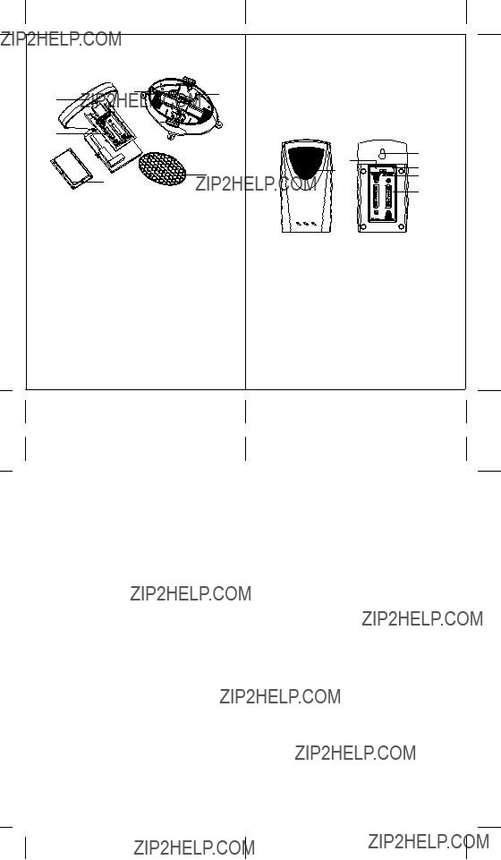

 ] will appear on the remote rainfall reading line and the indoor or remote temperature reading line of the main unit, warning that the corresponding batteries need replacement.
 ] will be displayed. Press and hold the front panel
  ) button on the main unit for two seconds or until Rain symbol will start flashing, to initiate a signal search for the remote rainfall. Press and hold the back panel
  ) button on the main unit for two seconds to initiate a signal search for the remote temperature.

 ??
?? ?? will appear on the display??s middle line below the remote temperature channel number. All 3 remote temperatures will be displayed
  ?? will disappear, returning the main unit to the default display mode.
 ?? ??is located to the left of the rainfall reading and indicates the reception status from the remote rain gauge. There are three following types of the reception status that may be displayed:
 ) button for 2 seconds to begin a new signal search. If the signal still isn??t received, please make sure that:
 ) button for 2 seconds to begin a new signal search.
 ) or
) or  ) to change flashing letters.
 ) or
) or  ).
).


