04973 Series Conductivity Cells
Installation and Maintenance Manual
Honeywell Field Solutions
04973 Series Conductivity Cells
Installation and Maintenance Manual
Honeywell Field Solutions

Copyright, Notices, and Trademarks
Printed in U.S.A. ??? ?? Copyright 2007 by Honeywell Inc.
Revision??? 10/07
Warranty/Remedy
Honeywell warrants goods of its manufacture as being free of defective materials and faulty workmanship. Contact your local sales office for warranty information. If warranted goods are returned to Honeywell during the period of coverage, Honeywell will repair or replace without charge those items it finds defective. The foregoing is Buyer's sole remedy and is in lieu of all other warranties, expressed or implied, including those of merchantability and fitness for a particular purpose. Specifications may change without notice. The information we supply is believed to be accurate and reliable as of this printing. However, we assume no responsibility for its use.
While we provide application assistance personally, through our literature and the Honeywell web site, it is up to the customer to determine the suitability of the product in the application.
Honeywell Field Solutions
512 Virginia Drive
Fort Washington, PA 19034
Brands or product names are trademarks of their respective owners

About This Document
Abstract
The purpose of this manual is to support the installation and maintenance of the 4973 Series Conductivity Cells.
Revision Notes
The following list provides notes concerning all revisions of this document.
410/05 Edit text and add electrical connection drawings for UDA2182 analyzer
510/07 Edit text, add CRN approval, add quick disconnect info.
References
Honeywell Documents
The following list identifies all Honeywell documents that may be sources of reference for the material discussed in this publication.

Contacts
World Wide Web
http://hpsweb.honeywell.com
Telephone
Contact us by telephone at the numbers listed below.


Figures
Figure
Analyzer or Connected to Junction Box ______________________________________________ 11 Figure
Analyzer_______________________________________________________________________ 13 Figure

Introduction
1. Introduction
1.1 Overview
The 4973 Type cells, Figure
Made of polyethersulfone (PES) construction for
The 4973 Cells used with UDA2182 Series or APT2000/4000 Series are equipped with the choice of:
???integral standard 20 or 50 foot lead
???quick disconnect cable option
???junction box type (universal) head with terminal connections for longer lead lengths.
For
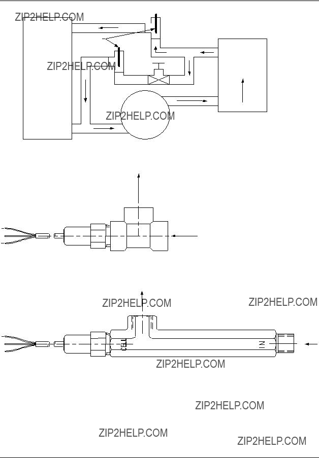
For flow applications, the cell can be installed directly into a process stream as shown in Figure
A 316SS (P/N 31079198) and a PES (P/N 055919) Flow Chamber is available from Honeywell.
1.2 Description
All conductivity cells of the 4973 Type are suitable for use in both flow and insertion - type installations. They are
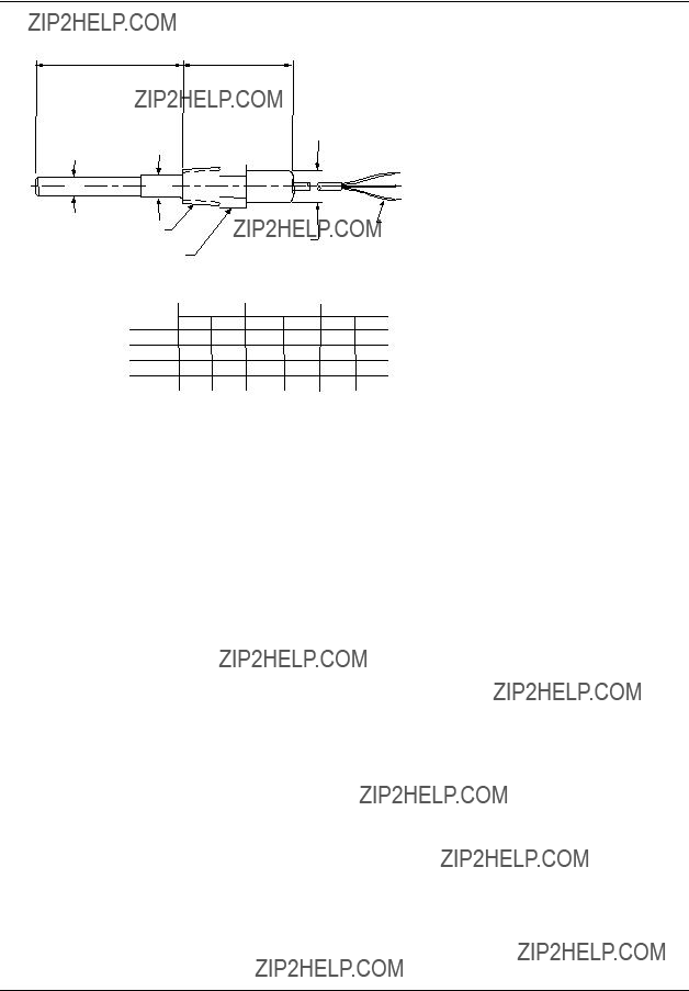
The physical appearance of the cells is shown in Figure
0.01 and 0.1 Cell Constants
The 0.01 cell differs from the others only by its outer electrode length of
1 and 10 Cell Constants
The 1 and 10 cell constant types are similar but differ in the width of flow channel (that serves to conduct the solution being measured past the electrodes of the cell) as well as size and spacing of the electrodes. The electrodes are graphite, 1/4??? D for the 1 cell constant and 1/8??? D for the 10 cell constant. The temperature compensating sensor is integral with the cell body.

Introduction
Insertion
Depth
(SeeFlow
Specifications) Holes
Titanium
Electrodes
FLOW
Potted
Potted
Connector
Connector
Housing *
11/8" Hex
 Across Flats
Conductivity
Cell
?????Conduit
Figure
ATTENTION
Do not remove the Teflon sheath on 1.0 and 10 constant cells.
Introduction
Figure
*Maximum allowable operating temperature
for piping arrangements depends on the type of pipe tee chosen.
Flow
(a) Cell Mounted in 3/4" NPT Pipe Tee* (Customer Supplied)
Flow
(b) Cell Mounted in PES Flow Chamber
a/n 23341
Figure

Specifications
2.Specifications
2.1Specifications for 04973 Series
2.2 Specifications for 055919 Flow Chamber
Installation
3. Installation
3.1 General Requirements
Observe the following before installing a conductivity cell. Specific requirements for particular types of installation are given in Sections 3.3 and 3.4.
???Do not remove the Teflon sheath on 1or 10 constant cells, as this will change the cell constant value.
???Do not use the cell in solutions which can affect the fittings or the cell materials. If in doubt, contact Honeywell.
???Avoid all chlorinated hydrocarbons.
Titanium and PES (0.01 and 0.1 cell constants) and Graphite, Teflon and PES (1.0 and 10 cell constants) are the only cell materials in contact with measured solutions. These materials are inert to corrosive chemicals such as mineral acids, oxidizing agents and caustic solutions.
???Avoid trapped air; see that air is not trapped in the cell flow channels.
???Do not use the cell in solutions having temperatures or pressures greater than the maximum limits stated in the Specifications.
???Avoid locations where the operator must take an awkward position to install or remove the cell.
???When tightening, do not exceed the torque limits provided in Section 3.5.
3.2The Differences between the Quick Disconnect and Integral Cable Option
The cable options of quick disconnect and integral cable do not affect the performance of the cell. These options only relate to how the cell is connected to the instrument.
ATTENTION
???The electrical connections are different for these options. Please refer to Section 4 for instructions.
???The wire colors for the integral cable and quick disconnect option are not the same.
???Integral cable means the cable is potted into the cell. The cable and cell are one entity and cannot be separated.
???The quick disconnect option means the cell is connected to the cell by a receptacle on the top of the cell. The cell and the cable are separate entities. When the time comes to replace the cell, the cable does not have to be replaced. The cable can simply be mated with another cell that has the quick disconnect option. This option can not be used in immersion applications.
ATTENTION
The quick disconnect cable can be purchased from Honeywell.

Installation
3.3
In addition to the General Requirements outlined above, note the following with regard to
???Make certain the liquid head is above the cell location during measurement. A vertical insertion (from above) or a horizontal insertion can be used.
???Allow at least
???It is usually best to have the solution flow up into the end of the cell since it is less likely to result in clogging by solids settling in the cell channels.
???To be sure that a representative sample is being measured at all times, the solution must continuously move through the cell channels. In a rapidly moving solution, the assembly may be mounted so that the existing circulation forces the solution through the channels. When measurements are made in quiescent solutions, artificial means must be provided to force the solution through the cell. In some cases, this may be accomplished by moving the cell up and down.
Installation
Tighten the cell into a 3/4??? NPT threaded opening (do not exceed a tightening torque greater than that indicated in Section 3.5) using a Teflon thread compound (preferably Teflon tape).
3.4
In addition to the General Requirements outlined in Section 3.1, note the following with regard to flow- type mounting:
???When mounting the cell in a pipe tee or flow chamber such as shown in Figure
???In general, the cell should be mounted so that the sample will flow through the channel toward the mounting end of the cell, exiting through the other channel hole or through the outer electrode holes. See Figure
???Locate the cell on the pressure side, not the vacuum side, of pumps. See Figure
???Avoid a horizontal cell mounting having the flow channel, see Figure
???The 3/4??? tee arrangement, Figure
Installation
1.Tighten the cell into a 3/4??? pipe tee (do not exceed a tightening torque greater than that indicated in Section 3.5).
2.If the
3.To avoid cracking the 055919 flow chamber, use Teflon tape on cell threads and tighten cell only enough to prevent leakage.
Installation
3.5 Torque Recommendations
For inserting a cell in metal fittings or bushings - 40
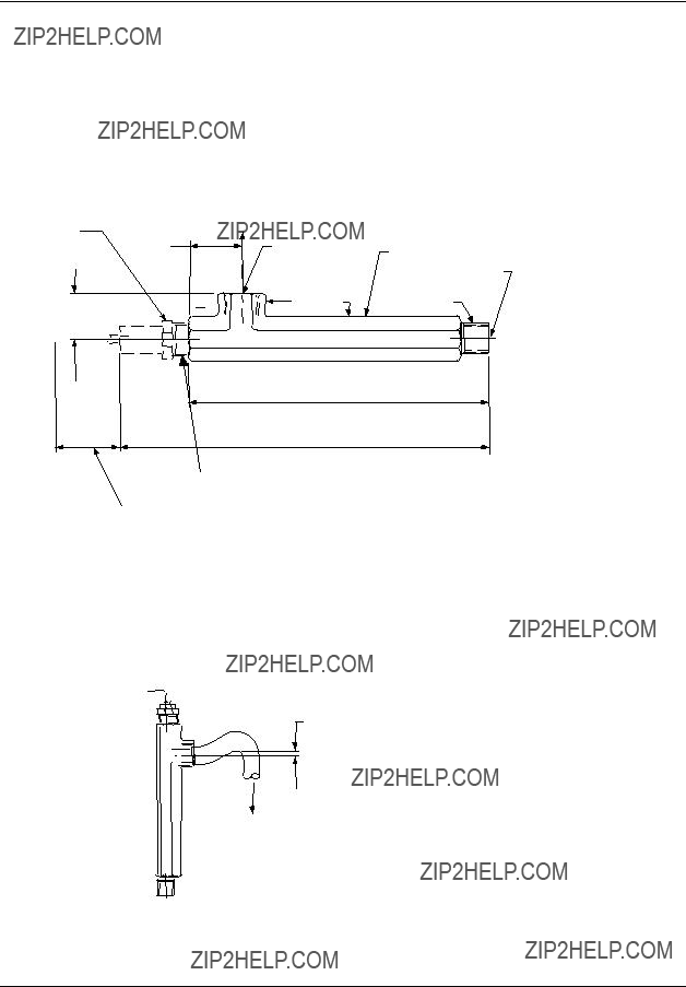
3.6 Dimension Drawings
8 3/4" (222mm)
14 1/2" max (368mm)
3/4" Fitting
Allow 4 1/8" (105mm) for re moval of cell
Notes:
1.Mount cell and flow chamber horizontally as shown above with flow exit up to eliminate possible air gap around cell body.
2.If cell and flow chamber must be mounted vertically, attach a short length of tubing to flow exit as shown below and form a trap to ensure filling of flow chamber, especially at low flow.

 CELL
CELL
IN
2" min. (51mm)
a/n23342
Figure
Installation
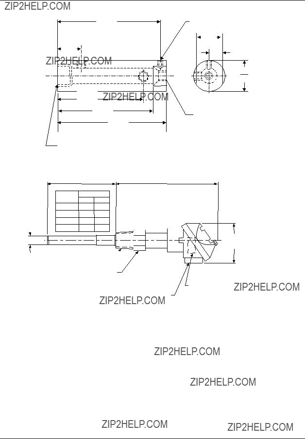
3/4 NPT
Figure
0.593" Dia.
(15mm) 
3/4" NPT
1.13" Hex (29mm)
????? female NPT for user's flexible electrical conduit
connection. For insertion or removal of cell, disconnect
conduit connections.
3/4???
(76mm)
Four Point Terminal Board for lead wire connections. Each
#12 or smaller AWG wire
NOTE: For existing users with conduit, a ????? x ????? adapter bushing will be required to use existing conduit.
Figure
Installation
"Z""Y"
Figure
Electrical Connections
4. Electrical Connections
4.1 Overview
The terminal board connections for the various Honeywell measuring instruments are given in the appropriate Figures in this section.
To avoid the possibility of AC pickup in the cell leads, separate them from all AC
ATTENTION
Do not use shielded cable except where shown in the following figures.
4.2 Instrument Wiring for 4973 Cells with Integral Cable
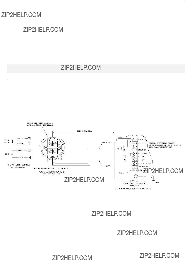
4.2.1 Model 4973 Series with Integral Cable to UDA2182 Analyzer
NOTES
1.
THEBLACKCELLELECTRODELEADNEARTHECELL.ALTERNATIVELY,CONNECTTOTHEUDA
GROUNDSCREW ASSHOWNDOTTED.DONOTGROUND10,25,OR50CONSTANTCELLS.
2.FORCELLLEADSBLACKANDWHITE,USE16TO22AWGCABLE,SHIELDEDTWISTEDPAIR, WITH30pFMAX.CAPACITANCEBETWEENCONDUCTORS.CONNECTSHIELDTOTERMINAL ???10???.FORMODEL4973INSTALLATIONSWITHHONEYWELL31079198SSFLOW CHAMBER,USE
22AWGMINIMUMCOAXIALCABLETYPERG59U(BELDEN9259OREQUIV.).CONNECTCOAX
SHIELDTOTERMINALS???A???AND???10???.CONNECTCOAXCONDUCTORTOTERMINALS???C???AND???7???.
3.FORCOMPENSATORLEADSBANDD,USE16TO22AWG,TWOCONDUCTORCABLE.
4.CELLTOANALYZERCABLESARECONSIDEREDLOW LEVEL.RUNSEPARATEFROMHIGH
LEVELWIRING.
DRAWING 50012874
Figure
Electrical Connections
50
YELLOW
COAX
20OR50FT.CABLELENGTH.
Direct Cell to Analyzer Installation
50
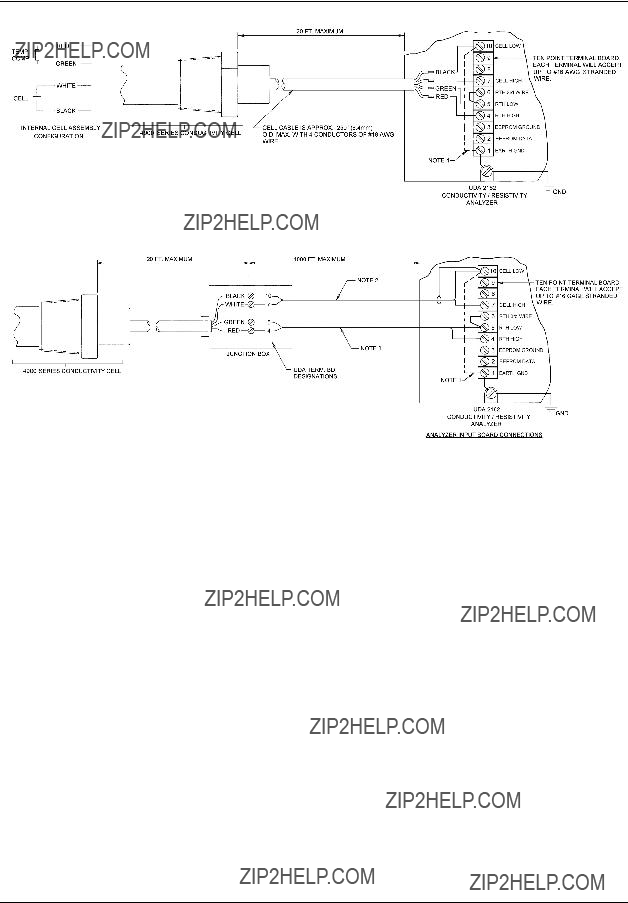
Cell to Analyzer through Junction Box
NOTES
5.
THEBLACKCELLELECTRODELEADNEARTHECELL.ALTERNATIVELY,CONNECTTOTHEUDA
GROUNDSCREW ASSHOWNDOTTED.DONOTGROUND10,25,OR50CONSTANTCELLS.
6.FORCELLLEADSBLACKANDWHITE,USE16TO22AWGCABLE,SHIELDEDTWISTEDPAIR, WITH30pFMAX.CAPACITANCEBETWEENCONDUCTORS.CONNECTSHIELDTOTERMINAL ???10???.FORMODEL4973INSTALLATIONSWITHHONEYWELL31079198SSFLOW CHAMBER,USE
22AWGMINIMUMCOAXIALCABLETYPERG59U(BELDEN9259OREQUIV.).CONNECTCOAX
SHIELDFROM???BLACK???TOTERMINAL???10???.CONNECTCOAXCONDUCTORFROM???WHITE???TO TERMINAL???7???.
7.FORCOMPENSATORLEADSREDANDGREEN,USE16TO22AWG,TWOCONDUCTORCABLE.
8.CELLTOANALYZERCABLESARECONSIDEREDLOW LEVEL.RUNSEPARATEFROMHIGH
LEVELWIRING.
DRAWING 50012875
Figure
Electrical Connections
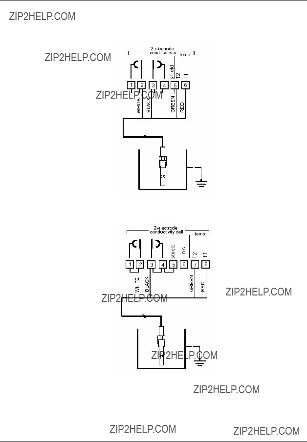
4.2.2 Model 4973 Series with Integral Cable to APT Series Analyzer/Transmitter
04973 series cells with integral cable leads connected to an APT4000
04973 series cells with integral cable leads connected to an APT2000
Figure
Electrical Connections
4.3 Instrument Wiring for 4973 Cells with Quick Disconnect Cable
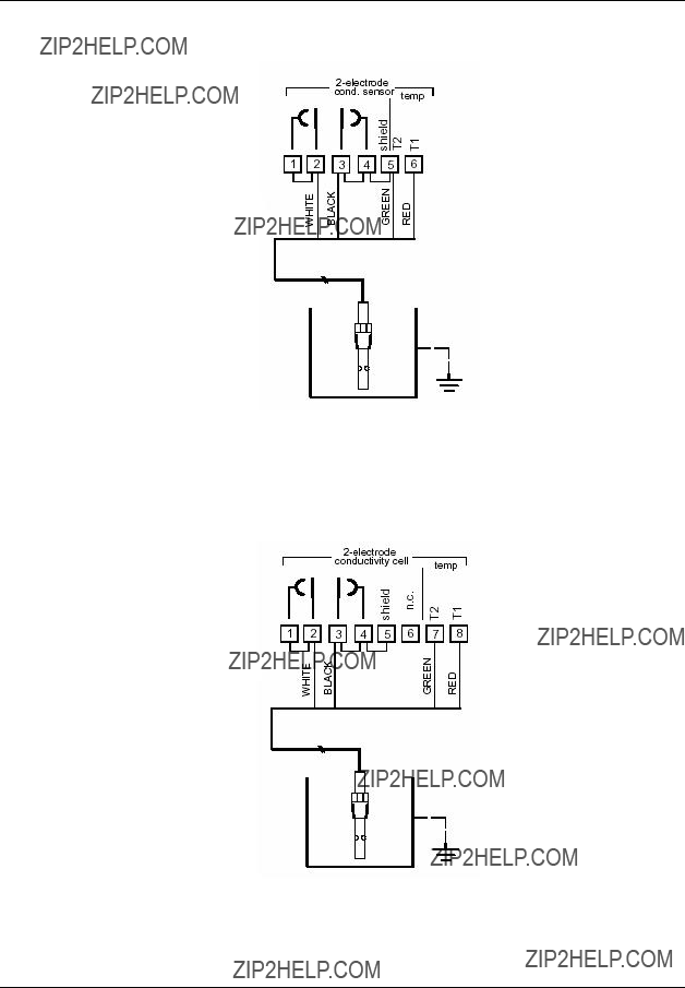
4.3.1 Wiring Model 4973 with Quick Disconnect Cable to UDA2182
Figure
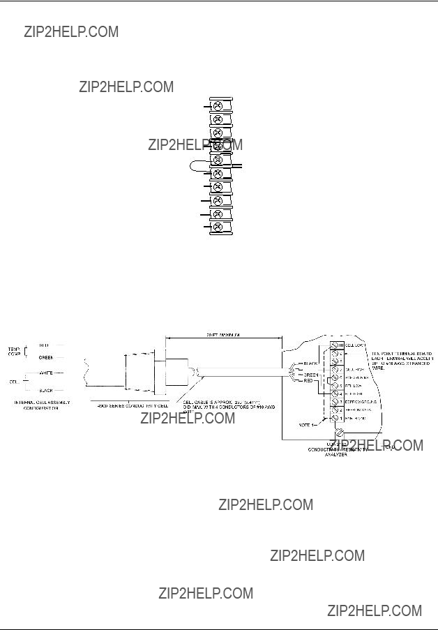
4.3.2 Wiring Model 4973 with Quick Disconnect Cable to Junction Box
50
YELLOW
COAX
20OR50FT.CABLELENGTH.
DRAWING 50012875
Figure
Electrical Connections
4.3.3 Wiring Model 4973 with Quick Disconnect Cable to APT
NOTE: IGNORE BLUE AND BROWN WIRES.
Figure
NOTE: IGNORE BLUE AND BLACK WIRES.
Figure
Maintenance
5. Maintenance
5.1 Overview
The only maintenance that may be required is occasional cleaning. When cleaning, avoid scratching electrode surfaces. Do not use a brush or pipe cleaner.
5.2 To Clean the Cell
The cell will require cleaning if sludge, slime, etc., accumulate in the flow channels. Since the materials of construction are chemically inert, chemical agents may be used and are recommended for cleaning the cells. The particular cleaning agent used must be selected according to the type of contamination to which the cell is exposed.
The cell housing is made of a polyethersulfone, PES, and must not be cleaned with acetone, chloroform, toluene, benzene, or other chlorinated hydrocarbons.
In general, a ???quick??? rinse in a 10% inorganic acid is effective and often adequate. Another method is to use a strong stream of water to dislodge particles; then reverse flush. After cleaning, rinse the cell thoroughly in tap water and then distilled water, if available. Take care not to scratch electrode surfaces.
5.3 Check Conductivity System
To check the conductivity system comprising the conductivity cell, leadwires, and measuring instrument, make a measurement in a reference solution of known conductivity. Alternatively, use a second cell having the same constant and temperature compensation and compare the two readings. Be sure the cells are not touching the bottom or sides of the container for this test.
If Table II of the conductivity cell model number is 333, the normal resistance of the temperature sensor as measured across the red (B) and green (D) leads is 8550 ohms at 25 C.
To check the electrode insulation, connect an ohmmeter across the black (A) and white (C) leads. With a dry and clean cell, the resistance should be greater than 50 megaohms.
5.4 Troubleshooting
A series of below normal conductivity readings could indicate that the cell is not filled with solution resulting in a lack of response.
If the plastic surface of the cell has a grayish dull appearance instead of its normal glassy appearance, the cell has been exposed to temperature above its specified maximum. Check the solution temperature and replace the conductivity cell.

Maintenance
5.5 Air Entrapped in Cell Flow Channel
If measurement errors appear for horizontal mountings of a 1 or 10 constant cell, it may be that air is entrapped in the cell flow channel. Take one of the following actions to eliminate this problem:
???Increase flow to at least 1 gpm.
???Rotate the cell mounting so that its flow channel faces the same direction as the pipeline flow exit.
???Install the cell and/or flow chamber vertically.

Accessories and Spare Parts
6. Accessories and Spare Parts
Note: For 10 constant cell, heat shrink the clear shield onto the cell using a 300??F max. temp. (Cal Factor may change)

Accessories and Spare Parts

Honeywell Field Solutions
512 Virginia Drive
Fort Washington, PA 19034