TR21, TR22, TR23, and TR24 Wall

Modules

INSTALLATION INSTRUCTIONS

FEATURES

The TR21, TR22, TR23, and TR24 family of wall modules include:

??? Models with setpoint adjustment.

??? Models with humidity output.

??? Models with occupied/unoccupied override (bypass) with LED.

??? Models with 3-position (auto/0/1) or 5-position (auto/0/1/2/3 speed) fan switch.

??? LONWORKS?? bus jack on all models except the TR21 and TR21-A models.

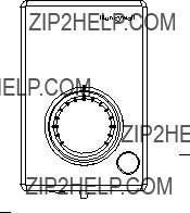
??? Locking cover on all models.

??? Operating range 45?? to 99?? F (7?? to 37?? C).

??? Models (TR22 and TR23) with user-selectable temperature setpoint dials in Fahrenheit, Celsius, and Relative (- to +).

PRODUCT DESCRIPTION

The TR21, TR22, TR23, and TR24 are a family of direct-wired wall modules for use with:

???Spyder Unitary Controllers: PUL, PVL

???Excel 10 W7750, W7751a, W7752, and W7753 controllers

???Honeywell Excel 800, 600, 500, 100, and 80 (all fully programmable) controllers

???W7761 Controller

???ComfortPoint LON Controllers: CP-UL, CP-VL

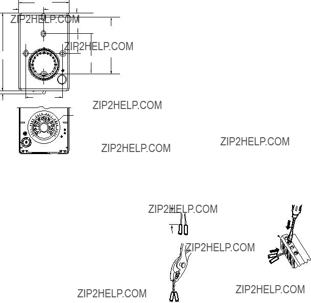
All models have a space temperature sensor. Some models have a temperature dial, setpoint adjustment, LONWORKS bus jack, override (bypass) with LED, and fan switch.

NOTE: Refer to the TR21, TR22, TR23, and TR24 Wall Modules ??? Specification Data, form 63-1321, for specific model features and additional information.

aThe TR21, TR22, TR23, and TR24 wall modules are not compatible with W7751A,C,E,G Controllers.

SPECIFICATIONS

Models: For specific model information, see TR21, TR22, TR23, and TR24 Wall Modules ??? Specification Data, form 63-1321.

Environmental Ratings:

???Operating Temperature: 45?? to 99?? F (7?? to 37?? C).

???Shipping Temperature: -40?? to 150?? F (-40?? to 65.5?? C).

Accessories: 50007298-001 (pack of 12) medium, cover plate; 6-7/8 x 5 in. (175 x 127 mm).

Approvals: CE; UL94 plastic enclosure; FCC Part 15, Class B

Temperature Sensor

TR21, TR22, TR23, and TR24 20K Ohm Nonlinearized

Sensor:

All models are furnished with a 20K Ohm nonlinear NTC temperature sensor that follows a specific temperature resistance curve. See Fig. 1 on page 2.

NOTE: The TR21-A wall module model has two (2) 20K Ohm nonlinear NTC temperature sensors in parallel, which provide 10K NTC temperature sensing necessary for averaging.

62-0267-09

TR21, TR22, TR23, AND TR24 WALL MODULES

Fig. 1. Temperature vs. Resistance for Nonlinear Sensor.

Communications

All wall modules (except the TR21 and TR21-A models) have a LONMARK?? bus communications port. If needed, the jack plug must be removed in the field, and terminals 3 and 4 wired according to the installation instructions.

The recommended wire size for the LONMARK?? bus is Level IV, 22 AWG (0.34 sq.mm) plenum or non-plenum rated, non-shielded, twisted pair, solid conductor wire.

Fig. 2. Wall Module Features (TR23-F Shown).

BEFORE INSTALLATION

CAUTION

Erratic System Operation Hazard.

Failure to follow proper wiring practices can introduce disruptive electrical interference (noise).

Keep wiring at least one foot away from large inductive loads such as motors, line starters, lighting ballasts, and large power distribution panels.

Shielded cable is required in installations where these guidelines cannot be met.

Ground shield only to grounded controller case.

IMPORTANT

All wiring must comply with local electrical codes and ordinances or as specified on installation wiring diagrams.

???Wall module wiring can be sized from 16 to 22 AWG (1.31 to 0.33 sq. mm) depending on the application.

???The maximum length of wire from a device to a wall module is 1000 ft. (305 m).

???Twisted pair wire is recommended for wire runs longer than 100 ft. (30.5 m).

INSTALLATION

Mount the wall module on an inside wall approximately 54 in. (1372 mm) from the floor (or in the specified location) to allow exposure to the average zone temperature. Do not mount the wall module on an outside wall, on a wall containing water pipes, or near air ducts. Avoid locations that are exposed to discharge air from registers or radiation from lights, appliances, or the sun. See ???Cover Disassembly??? on page 3.

The wall module can be mounted on a wall, on a standard utility conduit box using No. 6 (3.5 mm) screws or on a 60 mm wall outlet box (see Fig. 3). When mounting directly on a wall, use the type of screws appropriate for the wall material.

STANDARD UTILITY CONDUIT BOX

SUBBASE

NO. 6 SCREW

FRONT COVER

Fig. 3. Mounting on Standard Utility Conduit Box or 60 mm Wall Outlet Box (TR23 Shown).

Fig. 4. Wall Module Subbase Dimensions in Inches (mm) and Temperature Limit Set Screw Locations (TR23 Shown).

Cover Disassembly

TR21, TR22, TR23, AND TR24 WALL MODULES

3.Insert the wire in the required terminal location and tighten the screw to complete the termination.

4.Review and verify the terminal connection wiring and DIP switch settings illustrated in Table 1 on page 4.

NOTE: Wire the Lon connection (terminals 3 and 4) using Level IV 22 AWG (0.34 mm2) plenum or non-plenum rated, unshielded, twisted pair, solid conductor wire.

Wiring Examples

Table 1 on page 4 illustrates DIP switch settings and terminal connections for the wall modules. Refer to the TR21, TR22, TR23, and TR24 Wall Modules ??? Specification Data, form 63-1321, for additional DIP Switch information.

IMPORTANT

SW 2 on DIP Switch S2 is used for factory calibration of the temperature setpoint potentiometer. Depending on calibration, this switch may be set in either the On or Off position.

DO NOT change the position of this switch.

NOTES:

1.The TR21 and TR22 models do not use DIP Switch S1 and S3.

2.DIP Switch S1 is used only on the humidity models, TR21-H and TR23-H.

3.Models TR21 and TR21-A use terminals 1 and 2 only. Model TR21-J uses terminals 1, 2, 3, and 4 only.

A snap-fit locking mechanism is used to attach the cover of the wall module to its subbase. To disassemble the cover from the subbase:

1.Insert a thin, flat blade screwdriver into each of the two slots at the bottom of the module to release the two locking tabs. See Fig. 2 on page 2.

2.Tilt the cover out and away from the subbase to release the top two locking tabs.

3.To change the dial (e.g. from Fahrenheit to Celsius) release the two tabs on the inside of the front cover and remove the old dial.

Wiring

Attach the wires from the device sensor terminals to the appropriate wall module terminals. See Table 1 on page 4.

1.STRIP 1/2 IN.

1/2

(13 MM) FROM

(13)

WIRES TO BE

ATTACHED AT

ONE TERMINAL.

2.TWIST WIRES

TOGETHER

WITH PLIERS

(A MINIMUM OF

THREE TURNS).

CONTROLLER OR

WALL MODULE

E-BUS CONNECTOR

TERMINALS

3.CUT TWISTED END OF WIRES TO 3/16 IN. (5 MM) BEFORE INSERTING

INTO TERMINAL AND TIGHTENING

SCREW. THEN PULL ON EACH WIRE

IN ALL TERMINALS TO CHECK FOR

GOOD MECHANICAL CONNECTION.

M11413

CAUTION

Improper Electrical Contact Hazard.

Screw type terminal blocks are designed to accept no more than one 16 AWG (1.31 sq. mm) conductor.

Connect multiple wires that are 16-18 AWG (1.31-0.82 sq. mm) with a wire nut. Include a pigtail with this wire group and attach the pigtail to the individual terminal block.

Wiring Wall Modules

Wire the terminal block as follows:

1.For single wires, strip 3/16 in. (5 mm); for multiple wires going into one terminal, strip 1/2 in. (13 mm) insulation from the conductor.

2.If two or more wires (20 to 22 AWG only) are being inserted into one terminal, twist the wires together

before inserting. See Fig. 5.

Fig. 5. Attaching Two Wires (20 to 22 AWG) to Wall Module Terminals.

Attaching the Cover

When all wiring is complete, attach the cover of the Wall Module as follows:

1.Optional: For models with a temperature dial, insert the two setpoint screws into the inside of the cover to set the desired temperature range limit. See Fig. 4.

2.Press the cover straight down onto the subbase until it snaps into place.

3.For models with a temperature dial, insert the desired dial through the opening in the cover. Align the keyed shaft on the knob with the keyed slot into the fitting on the subbase, then press down until it snaps into place.

TR21, TR22, TR23, AND TR24 WALL MODULES

Wiring and DIP switch settings:

See Table 1 to determine DIP switch positions and terminal usage for each controller.

Table 1. DIP Switch Settings and Terminal Connections.

TR22-TR24 Terminal Connections

TR22 and TR23 Setpoint Adjustment

For the TR22 and TR23 Wall Modules with a setpoint adjustment, the controller must be programmed for the values in Table 2 and Table 3.

Table 2. Setpoint Values.

TR23-KL and TR23-H-KL

The TR23-KL and TR23-H-KL ship in packs of 20 and are supplied without setpoint adjustment knobs. Knobs can be ordered separately. See Table 4 for Knob model numbers.

TR21, TR22, TR23, AND TR24 WALL MODULES

Humidity Settings (DIP switch S1)

The humidity sensing control mode is set with this 2-position DIP switch. Refer to Fig. 4 on page 3 for location of DIP switch S1.

NOTE: These switch settings apply only to the TR21-H and TR23-H models.

To change the setting, first disconnect the power, then set SW1 and SW2 according to Table 5.

Table 5. DIP Switch S1 Settings.

TR23 and TR24 Wall Module Override

(Bypass) Pushbutton and LED

Operation

When Used With Excel 10 Controllers:

The Excel 10 controllers (W7750, W7751, W7752, and W7753) provide timed occupied and unoccupied temperature setpoints for the Wall Module, see Fig. 6. The override pushbutton is used to change the controller into the modes shown in Table 6 and illustrated in Fig. 7 on page 6. The override (bypass) LED displays the override status of the controller.

LED

1

OVERRIDE (BYPASS)

PUSHBUTTON

1LED AND OVERRIDE (BYPASS) PUSHBUTTON AVAILABLE

ONLY ON THE TR23 AND TR24 MODELS.

M28144

Fig. 6. LED and override pushbutton locations (TR23-F Wall Module shown).

TR21, TR22, TR23, AND TR24 WALL MODULES

Table 6. Wall Module Operation.

Fig. 7. Override pushbutton operation.

When Used With Excel 600/500/100/80/50 Controllers:

The application engineer/programmer can program the override (bypass) and LED to operate in any manner desired. The override (bypass) input is a dry contact, normally open, momentary digital input when the wall module does not have a fan switch. When a fan speed switch (basically a series of resistances based on fan switch position) is present, the override button is an analog input. See Table 4 for resistances.

When Used With T7350 Thermostat:

TR21, TR21-A, TR21-H, TR22, TR23, and TR24 are the models compatible with the T7350 thermostat. When using with the T7350 thermostat be sure to use the relative +/- offset knob only. The Celsius and Fahrenheit knobs will not work properly with the T7350 Thermostat.

TR22-F5, TR23-F3, and TR23-F5 Wall

Module Fan Switch

With the switch in the far left position (Auto), the fan automatically runs at the speed determined by the controller temperature control algorithm.

With the switch in the 0 position, the fan is off. Position 1 is fan speed 1, etc.

The wall module fan speed switch overrides the temperature control algorithm.

When Used With Excel 10 Controllers:

The Excel 10 Controllers (W7750, W7751, W7752, and W7753) can be programmed so that the fan speed switch and override button function the way that the application engineer/ programmer wants. See Table 7 for controller-programming resistances. Switch 1 on Dip Switch S2 adds 10k Ohms resistance when OPEN (for Excel 600-80 controllers) and removes it when CLOSED (for Excel 10 controllers).

Table 7. Program Settings for Wall Modules with Fan Switch using Excel 10 Controllers.

When Used With Excel 600/500/100/80/50 Controllers:

Excel 600/500/100/80 Controllers can be programmed so that the fan speed switch and override button function the way that the application engineer/programmer wants. See Table 8 for controller-programming resistances. Switch 1 on Dip Switch S2 adds 10k Ohms resistance when OPEN (for Excel 600-80 controllers) and removes it when CLOSED (for Excel 10 controllers).

Table 8. Program Settings for Wall Modules with Fan Switch using Excel 600/500/100/80 Controllers.

TR21, TR22, TR23, AND TR24 WALL MODULES

TR21, TR22, TR23, AND TR24 WALL MODULES

LONWORKS?? is a registered trademark of Echelon?? Corporation.

LONMARK?? and the LonMark Logo are trademarks of the LonMark Association.