IS3480 QuantumE ??
Scan Engine
User???s Guide
IS3480 QuantumE ??
Scan Engine
User???s Guide
Disclaimer
Honeywell International Inc. (???HII???) reserves the right to make changes in specifications and other information contained in this document without prior notice, and the reader should in all cases consult HII to determine whether any such changes have been made. The information in this publication does not represent a commitment on the part of HII.
HII shall not be liable for technical or editorial errors or omissions contained herein: nor for incidental or consequential damages resulting from the furnishing, performance, or use of this manual.
This document contains propriety information that is protected by copyright. All rights reserved. No part of this document may be photocopied, reproduced, or translated into another language without the prior written consent of HII.
?? 2004 - 2010 Honeywell International Inc. All rights reserved.
Web Address: www.honeywellaidc.com
Trademarks
Metrologic, QuantumE, CodeGate, MetroSelect and MetroSet2 are trademarks or registered trademarks of Metrologic Instruments, Inc. or Honeywell International Inc.
Microsoft, Windows 95, and Windows are registered trademarks of Microsoft Corporation.
IBM is a trademark of International Business Machines Corporation.
Checkpoint is a registered trademark of Checkpoint Systems, Inc.
Other product names mentioned in this manual may be trademarks or registered trademarks of their respective companies and are the property of their respective owners.

TABLE OF CONTENTS

TABLE OF CONTENTS
iii

INTRODUCTION
QuantumE ?? is a miniature,
Key Product Features
???Fully Automatic Scanning Operation
???Custom Configurable Scan Pattern
???
???Decoding of All Standard 1D and GS1 DataBar??? (RSS) Bar Codes
???Data Editing
???Seven Beeper Tones
???Configurable Depth of Field
???Flash - Upgradeable Firmware
???CodeGate??
???Sunrise 2005 Compliant
??? Applicable for IBM?? Host applications.
1

INTRODUCTION
Scanner and Accessories
**Contact a customer service representative for additional information on the MVC cable series and the host connections available.
Other items may be ordered for the specific protocol being used. To order additional items, contact the dealer, distributor or customer service. See page 52 for contact information.
2

INTRODUCTION
Scanner and Accessories
Part No.
OPTIONAL ACCESSORIES
Description
Keyboard Wedge PowerLink cable
Stand Alone Keyboard PowerLink cable
Low Speed USB
Utility Flex Cable
Communication Cable, Host end Not Terminated straight cord, short strain relief
Other items may be ordered for the specific protocol being used. To order additional
items, contact the dealer, distributor or customer service. See page 52 for contact information.
Maintenance
Smudges and dirt on the unit's window can interfere with the unit's performance. If the window requires cleaning, use only a mild glass cleaner containing no ammonia. When cleaning the window, spray the cleaner onto a lint free, non- abrasive cleaning cloth then gently wipe the window clean.
If the unit's case requires cleaning, use a mild cleaning agent that does not contain strong oxidizing chemicals. Strong cleaning agents may discolor or damage the unit's exterior.
3

INTRODUCTION
Scanner Components
Figure 1a. Scanner Components
1 Utility Connector Located Under Rubber Seal
The rubber seal protecting the utility connector should only be removed if the utility connector is to be used.
2
3Blue, White and Yellow LED Indicators
4Red Output Window (Laser Aperture)
5Pin Hole for Cable Release
6Speaker
7Three M2.5 x 0.45 Threaded Mounting Points
8Two M2.5 x 0.45 Threaded Mounting Points
9Button
Cable Removal
1.Locate the small ???pinhole??? on the side of the QuantumE near the cable (item 5 in figure 1a).
2.Bend an ordinary paperclip into the shape shown.
3.Insert the paperclip (or other small metallic pin) into the ???pinhole???.
4.There will be a faint ???click??? when the cable lock is
4

INTRODUCTION
Caution and Serial Number Labels
Figure 2.
Caution
To maintain compliance with applicable standards, all circuits connected to the scanner must meet the requirements for SELV (Safety Extra Low Voltage) according to EN/IEC
To maintain compliance with standard CSA C22.2 No.
Mounting Specifications
Figure 3.
5
INSTALLATION
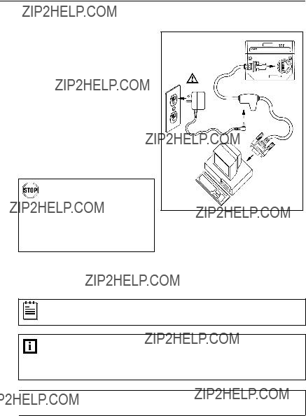
RS232, RS232 TTL, Light Pen or Laser Emulation
1.Turn off the host device.
2.Plug the male
3.Connect the
Note: Skip to step 6 if receiving power from the host device.
4.Plug the external power supply into the power jack on the PowerLink cable.
Check the AC input requirements of the power supply to make sure the
voltage matches the ACFigure 4. outlet. The outlet must be
located near the equipment and be easily accessible.
5.Connect AC power to the transformer.
6.Turn on the host device.
When the scanner first receives power, the blue LED will turn on; the scanner will simultaneously beep once and flash the white LED.
Plugging the scanner into the serial port of the PC does not guarantee that scanned information will appear at the PC.
A software driver and correct configuration setting are also required for proper communication to occur.

 See page 5.
6
INSTALLATION
RS485???
1.Turn off the host device.
2.Plug the male
3.Connect the other end of the MVC cable to the host device.
4.Turn on the host device.
Figure 5.
When the scanner first receives power, the blue LED will turn on; the scanner will simultaneously beep once and flash the white LED.
Plugging the scanner into the serial port of the PC does not guarantee that scanned information will appear at the PC. A software driver and correct configuration setting are also required for proper communication to occur.

 See page 5.
??? Applicable for IBM?? Host applications.
7

INSTALLATION
Keyboard Wedge
When the scanner first receives power, the blue LED will turn on; the scanner will simultaneously beep once and flash the white LED.
Powering the IS3480 directly from the host device can sometimes cause interference with the operation of the scanner or the computer. Not all computers supply the same current through the keyboard port. For this reason, Honeywell recommends using an external power supply. For additional information, contact a customer service representative.

 See page 5.
8
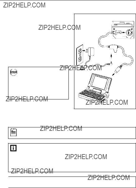
INSTALLATION
1.Turn off the host device.
2.Plug the male
3.Connect the other end of the PowerLink cable to the keyboard port on the host device.
4.Plug the external power supply into the power jack on the PowerLink cable.
When the scanner first receives power, the blue LED will turn on; the scanner will simultaneously beep once and flash the white LED.
Powering the IS3480 directly from the host device can sometimes cause interference with the operation of the scanner or the computer. Not all computers supply the same current through the keyboard port. For this reason, Honeywell recommends using an external power supply. For additional information contact a customer service representative.

 See page 5.
9

When the scanner first receives power, the blue LED will turn on; the scanner will simultaneously beep once and flash the white LED.
Plugging the scanner into the USB port of the PC does not guarantee that scanned information will appear at the PC. A software driver and correct configuration setting are also required for proper communication to occur.

 See page 5.
10

INSTALLATION
Notes for Laser Emulation
The
If the Recall Defaults bar code is scanned while reconfiguring the scanner, the laser emulation mode will no longer be enabled.
Scan the following bar code to
Enable Laser Emulation Mode
?? 9 9 9 9 7 9
11

SCANNER OPERATION
Configurable Primary and Secondary Scan Pattern Modes
There are two configurable scan pattern modes available with the IS3480.
???The primary scan pattern mode is the default scan pattern active when the scanner starts.
???The secondary scan pattern mode is activated by pressing the button located on the side of the scanner. This mode is also referred to as the button mode. For additional information on QuantumE???s button modes and an example of each, please refer to Configurable Button Functions below.
The scanner returns to the primary scan pattern mode after a double click of the button or if the unit has not scanned a bar code for the duration of a
Each pattern mode can be configured to use one of three scan patterns listed below. Please refer to the MetroSelect Configuration Guide for information on changing the default scan pattern settings.
???all scan lines on (omnidirectional reading)
???
???horizontal raster
If CodeGate is enabled, it will apply to the secondary pattern mode when scanning. For detailed information on CodeGate and the button refer to the Configurable Button Functions.
Configurable Button Functions
The button on the side of the IS3480 can be configured to function in one of four modes.
???Button Click Mode, with CodeGate Enabled (Default)
???Button Click Mode, with CodeGate Disabled
???Button Hold Mode, with CodeGate Enabled
???Button Hold Mode, with CodeGate Disabled
The following pages include examples of how the button will function when the unit has been configured to operate in each of the four button modes.
12

SCANNER OPERATION
Configurable Button Functions
SECONDARY SCAN PATTERN
BUTTON CLICK MODE WITH CODEGATE ENABLED
For illustration purposes the unit???s primary scan pattern has been set to all scan lines (omnidirectional reading) and the secondary pattern has been set to
1.The primary scan pattern is active when the scanner starts.
2.To activate the secondary scan pattern, press and release the button.
3.To decode and transmit the bar code, press and release the button.
The scanner will beep once.
4.To reactivate the primary scan pattern, double click the button or after
13

SCANNER OPERATION
Configurable Button Functions
SECONDARY SCAN PATTERN
BUTTON CLICK MODE WITH CODEGATE DISABLED
For illustration purposes the unit???s primary scan pattern has been set to all scan lines (omnidirectional reading) and the secondary pattern has been set to
1.The primary scan pattern is active when the scanner starts.
2.To activate the secondary scan pattern, press and release the button.
3.The unit will beep once as it decodes and transmits the bar code.
4.To reactivate the primary scan pattern, double click the button or after
14

SCANNER OPERATION
Configurable Button Functions
SECONDARY SCAN PATTERN
BUTTON HOLD MODE WITH CODEGATE ENABLED
For illustration purposes the unit???s primary scan pattern has been set to all scan lines (omnidirectional reading) and the secondary pattern has been set to
1.The primary scan pattern is active when the scanner starts.
2.To activate the secondary scan pattern, press and hold the button.
3.To scan the bar code, align the laser line over the bar code while continuing to hold down the button.
4.To transmit the bar code, release the button. The scanner will beep once.
5.To scan and transmit additional bar codes, repeat steps 2 through 4.
6.The primary scan pattern will automatically reactivate after the button is released and no bar code is present in the scan field.
15

SCANNER OPERATION
Configurable Button Functions
SECONDARY SCAN PATTERN
BUTTON HOLD MODE WITH CODEGATE DISABLED
For illustration purposes the unit???s primary scan pattern has been set to all scan lines (omnidirectional reading) and the secondary pattern has been set to
1.The primary scan pattern is active when the scanner starts.
2.To activate the secondary scan pattern, press and hold the button.
3.To scan and transmit the bar code, align the laser line over the bar code while continuing to hold down the button. The scanner will beep once to indicate the bar code has been scanned and transmitted.
4.The primary scan pattern will automatically reactivate after the button is released and no bar code is present in the scan field.
16
SCANNER OPERATION
Sweet Spot Mode
The sweet spot mode is used to determine where the maximum read rate area or ???sweet spot??? is located for a specific bar code type. When activated this mode provides visual and audible feedback indicating how the scanner is scanning.
For further information on the sweet spot mode and instructions on how to enable it, refer the MetroSelect Configuration Guide
17

SCANNER OPERATION
Audible Indicators
When the IS3480 is in operation, it can provide audible feedback. These sounds indicate the status of the scanner. Eight settings are available for the tone of the beep (normal, six alternate tones and no tone). For instruction on how to change the tone of the beeper, refer to the MetroSelect Configuration Guide
One Beep
When the scanner first receives power the white LED will flash, the blue LED will turn on and the scanner will beep once (the white LED will remain on for the duration of the beep). The scanner is now ready to scan.
When the scanner successfully reads a bar code, the white LED will flash and the scanner beeps once (if configured to do so). If the scanner does not beep once and the white light does not flash, then the bar code has not been successfully read.
Razzberry Tone
This is a failure indicator. Refer to Failure Mode Indicators on page 20.
Three Beeps - during operation
When placing the scanner in configuration mode, the white LED will flash while the scanner simultaneously beeps three times. The white and blue LEDs will continue to flash until the unit exits configuration mode. Upon exiting configuration mode, the scanner will beep three times and the white LED will stop flashing.
When configured, three beeps can also indicate a communications timeout during normal scanning mode.
When using
Three Beeps - on power up
This is a failure indicator. Refer to Failure Mode Indicators on page 20.
18

SCANNER OPERATION
Visual Indicators
There are four LEDs located on the top of the IS3480. When the scanner is on, the flashing or constant illumination of the LEDs indicates the status of the current scan and the scanner.
No LEDs
The LEDs will not be illuminated if the scanner is not receiving power from the host or transformer. They are also not illuminated when all lasers are turned off for any reason.
Steady Blue
When the laser is active, the blue LED is illuminated. The blue LED will remain illuminated until the laser is deactivated.
Steady Blue and Single White Flash
When the scanner successfully reads a bar code, the white LED will flash and the scanner will beep once. If the white LED does not flash or the scanner does not beep once, then the bar code has not been successfully read.
Steady White and Blue
After a successful scan, the scanner transmits the data to the host device. Some communication modes require that the host inform the scanner when data is ready to be received. If the host is not ready to accept the information, the scanner???s white LED will remain on until the data can be transmitted.
Alternating Blue and White Flashes
This indicates the scanner is in program mode. A razzberry tone indicates that an invalid bar code has been scanned in this mode.
Steady White, Blue Off
This indicates the scanner may be waiting for communication from the host.
19

SCANNER OPERATION
Failure Mode Indicators
Flashing Blue and One Razzberry Tone
This indicates that the scanner has experienced a laser subsystem failure. Return the unit to an authorized service center for repair.
Flashing Blue and White and Two Razzberry Tones
This indicates that the scanner has experienced a motor failure. Return the unit to an authorized service center for repair.
Continuous Razzberry Tone with Both LEDs Off
If, upon power up, the scanner emits a continuous razzberry tone, then the scanner has an electronic failure. Return the unit to an authorized service center for repair.
Three Beeps - On Power Up
If the scanner beeps three times on power up then, the nonvolatile memory that holds the scanner configuration has failed. Return the unit to an authorized service center for repair.
20

SCANNER OPERATION
Depth of Field Specifications*
Normal Scan Zone
Specifications are based on a 0.33 mm (13 mil) bar code.
Figure 9. Normal Depth of Field
* All specifications are subject to change without notice.
21

SCANNER OPERATION
Depth of Field Specifications*
Reduced Scan Zone
Specifications are based on a 0.33 mm (13 mil) bar code.
Figure 10. Reduced Depth of Field
* All specifications are subject to change without notice.
22

SCANNER OPERATION
Depth of Field by Bar Code Element Width*
Normal Scan Zone
MINIMUM BAR CODE ELEMENT WIDTH
Figure 11. Normal Scan Zone by Bar Code Element Width
* All specifications are subject to change without notice.
23

SCANNER OPERATION
Depth of Field by Bar Code Element Width*
Reduced Scan Zone
MINIMUM BAR CODE ELEMENT WIDTH
Figure 12. Reduced Scan Zone by Bar Code Element Width
* All specifications are subject to change without notice.
24
SCANNER OPERATION
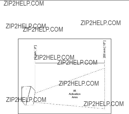
IR Activation Range*
QuantumE???s default power save mode??? is Laser OFF. This power save mode turns the laser off after a configured period of
Figure 13. IR Activation Range
* All specifications are subject to change without notice.
???Refer to the MetroSelect Configuration Guide
25
TROUBLESHOOTING GUIDE
The following guide is for reference purposes only. Contact a Honeywell representative to preserve the limited warranty terms on page 47.
All Interfaces
Check the transformer, outlet and power strip. Make sure the cable is plugged into the scanner.
Some host systems cannot supply enough current to power the IS3480. Use the power supply included with the scanner.
Adjust the same symbol timeout for a longer time increment.
Enable the beeper.
Select a tone.
The unit powers up but does not scan and/or beep.
The unit is trying to scan a particular symbology that is not enabled.
The scanner has been programmed for a character length lock, or a minimum length and bar code being scanned does not satisfy the configured criteria.
UPC/EAN, Code 39, Interleaved 2 of 5, Code 93, Code 128 and Codabar are enabled by default. Verify that the type of bar code being read has been selected
Verify that the bar code that is being scanned falls into the criteria.
Typical of
Verify that the scanner???s data format matches the format required by the host.
Make sure that the scanner is connected to the proper host port.
26
TROUBLESHOOTING GUIDE
All Interfaces
The unit scans a bar code, but locks up after the first scan (the white LED stays on).
Scanner beeps at some bar codes and NOT for others of the same bar code symbology.
During power up the unit beeps three times.
During power up the unit razzes continuously.
During power up the unit razzes once and the blue LED flashes.
During power up the unit razzes twice and both LEDs flash.
The scanner is configured to support some form of host handshaking but is not receiving the signal.
The bar code may have been printed incorrectly.
The scanner is not configured correctly for the type of bar code.
The minimum symbol length setting does not work with the bar code.
There is a
There has been a diagnostic failure.
There is a VLD failure.
There is a scanner motor failure.
If the scanner is setup to support ACK/NAK, RTS/CTS, XON/XOFF or D/E, verify that the host cable and host are supporting the handshaking properly.
Check if it is a check digit, character or border problem.
Check if check digits are set properly.
Check if the correct minimum symbol length is set.
Contact a service representative.
Contact a service representative.
Contact a service representative.
Contact a service representative.
27

TROUBLESHOOTING GUIDE
28
DESIGN SPECIFICATIONS
IS3480
Operational
Normal Depth of Field: 25 mm - 280 mm (1"- 11") Reduced Depth of Field: 25 mm - 150 mm (1"- 6")
Omni Scan
Scan Speed: 1650 scan lines per second No. of Scan Lines: 20
Scan Speed: 80 scan lines per second No. of Scan Lines: 1
Raster
0.33 mm (13 mil) bar code
??? Applicable for IBM?? Host applications. Specifications subject to change without notice.
29

DESIGN SPECIFICATIONS
IS3480
Mechanical
For regulatory compliance information, see pages 44 ??? 46.
Environmental
Operating Temperature:
Storage Temperature:
Humidity: 5% to 95% relative humidity,
Ventilation: None required
Specifications subject to change without notice.
30

APPLICATIONS AND PROTOCOLS
The model number on each scanner includes the scanner number and factory default communications protocol.
47Keyboard Wedge,
104RS232 Transistor to Transistor Logic (TTL), Laser Emulation
???Applicable for IBM?? Host applications.
The IS3480 scanner with
The following are the most important selectable options specific to the keyboard wedge.
Keyboard Type
???** AT (includes IBM?? PS2 models 50, 55, 60, 80)
???IBM PS2 (includes models 30, 70, 8556)
Keyboard Country Type
**Default setting. Refer to the MetroSelect?? Configuration Guide
(MLPN
31

CONFIGURATION MODES
The IS3480 Series scanner has three modes of configuration.
???Bar Codes
The IS3480 can be configured by scanning the bar codes included in the
???MetroSet2
This
???Serial Programming
This mode of configuration is ideal for OEM applications. Serial programming mode gives the
32

UPGRADING THE FIRMWARE
The IS3480 is part of Honeywell's line of scanners with flash upgradeable firmware. The upgrade process requires, a new firmware file supplied to the customer by a customer service representative??? and Honeywell's MetroSet2 software??????. A personal computer running Windows 95 or greater with an available RS232 serial or USB port is required to complete the upgrade.
Do not use the standard cable supplied with Keyboard Wedge or RS485??? IS3480 interface kits for firmware upgrades. If using USB or RS232 for the upgrade process, the standard USB or RS232 cable provided with the scanner can be used.
To upgrade the firmware in the IS3480:
1.Plug the scanner into a serial communication port on the host system.
2.Start the MetroSet2 software.
3.Click on the plus sign (+) next to POS Scanners to expand the supported scanner list.
4.Choose the Quantum E/T from the list.
5.Click on the Configure Quantum E/T Scanner button.
6.Choose Flash Utility from the options list located on the left side of the screen.
7.Click on the Open File button in the Flash Utility window.
8.Locate and open the flash upgrade file supplied.
9.Select the COM port that the scanner is connected to on the host system.
10.Verify the settings listed in the Flash Utility window.
11.Click on the Flash Scanner button to begin the flash upgrade.
12.A message will appear on the screen when the upgrade is complete.
???See Contact Information on page 47.
??????MetroSet2 is available for download, at no additional cost, from www.honeywellaidc.com.
???Applicable for IBM?? Host applications.
33

DEFAULT SETTINGS - COMMUNICATION PARAMETERS
Many functions of the scanner can be "configured" - that is enabled or disabled. The scanner is shipped from the factory configured to a set of default conditions. The default parameter of the scanner has an asterisk ( * ) in the charts on the following pages. If an asterisk is not in the default column then the default setting is Off or Disabled. Not every interface supports every parameter. If the interface supports a parameter listed in the charts on the following pages, a check mark (???) will appear.
??? Applicable for IBM?? Host applications.
34

DEFAULT SETTINGS - COMMUNICATION PARAMETERS
??? Applicable for IBM?? Host applications.
35
DEFAULT SETTINGS - COMMUNICATION PARAMETERS
Transmit
Check Digit
Transmit
Check Digit
Expand
Convert
Transmit Lead Zero on
Convert
Transmit
Number System
Transmit
Manufacturer ID#
Transmit
Transmit Codabar
Start/Stop Characters
CLSI Editing (Enable)
Transmit Mod 43 Check Digit on Code 39
Transmit Code 39
Stop/Start Characters
Transmit Mod 10/ITF
*?????? ??????
?????? ??????
?????? ??????
?????? ??????
?????? ??????
?????? ??????
* ?????? ??????
* ?????? ??????
*?????? ??????
 ?????? ??????
 ?????? ??????
 ?????? ??????
?????? ??????
 ?????? ??????
??? Applicable for IBM?? Host applications.
36
??? Applicable for IBM?? Host applications.
37

DEFAULT SETTINGS - COMMUNICATION PARAMETERS
Supplements are not Required
Two Digit Redundancy
Five Digit Redundancy
100 msec to Find Supplement Programmable in 100msec steps (MAX 800 msec)
Coupon Code 128
Programmable Code
Lengths
Programmable Prefix
Characters
Programmable Suffix
Characters
Prefixes for individual Code Types
Editing
Inter
(100 ??sec steps)
Function/Control Key
Support
Minimum Element Width Programmable in 5.6 ??sec steps
Normal Depth of Field
Reduced Depth of Field
Sweet Spot Mode
*?????? ?????? ??????
 ?????? ?????? ??????
 ?????? ?????? ??????
??? Applicable for IBM?? Host applications.
38
SCANNER AND CABLE TERMINATIONS
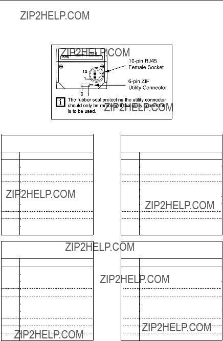
Scanner Pinout Connections
The IS3480 scanner interfaces terminate to a
The serial number label indicates the interface enabled when the scanner is shipped from the factory.
Figure 14.
and
Pin Function
1Ground
2RS232 Transmit Output
3RS232 Receive Input
4PC Data
5PC Clock
6KB Clock
7PC +5V
8KB Data
9+5VDC
10 Shield Ground
RS232 Low Speed USB
Pin Function
1Ground
2RS232 Transmit Output
3RS232 Receive Input
4RTS Output
5CTS Input
6D+
7V_USB
8D-
9+5VDC
10 Shield Ground
RS232 and Light Pen Emulation
Pin Function
1Ground
2RS232 Transmit Output
3RS232 Receive Input
4RTS Output
5CTS Input
6DTR Input/LTPN Source
7Reserved
8LTPN Data
9+5VDC
10 Shield Ground
RS485???
Pin Function
1Ground
2RS232 Transmit Output
3RS232 Receive Input
4RTS Output
5CTS Input
6DTR Input
7IBM
8IBM A+ Receive
9+5VDC
10 Shield Ground

SCANNER AND CABLE TERMINATIONS
Figure 15.
Pin Function
1Ground
2RS232 Transmit Output
3RS232 Receive Input
4RTS Output (TTL RS232) / Flip Sense
5CTS Input (TTL RS232) / Trigger Emulation Output
6DTR Input (TTL RS232) / Scan Enable
7Receive (TTL RS232) / Good Read
8Transmit (TTL RS232) / Scan Data
9+5VDC
10 Shield Ground
40

SCANNER AND CABLE TERMINATIONS
Figure 16.
Figure 17.
Zero Insertion Force Connector (ZIF),
Pin Function
1Aux +5V: Power out. Can supply up to 100mA @ 5V.
Good Read:
232 ms at a baud rate of 9600. Represents a successful bar code read. Can be used to drive an external LED. Requires an external current limiting resistor of 182 ohms.
Aux Beeper:
3at a frequency of 16.67 kHz for duration of 60 ms. Represents a successful bar code read. Can be used to drive an external beeper.
4Aux Active: Active HIGH input signal for external trigger. A HIGH on this pin is equivalent to activating the scan push button.
5Aux Out: Reserved.
6Ground
41

SCANNER AND CABLE TERMINATIONS
Cable Connector Configurations (Host End)
Stand Alone Keyboard PowerLink
Cable
PinFunction
1PC Data
2No Connect
3Power Ground
4+5VDC PC Power to KB
6 No Connect
42

SCANNER AND CABLE TERMINATIONS
Cable Connector Configurations (Host End)
Honeywell will supply an adapter cable with a
43

REGULATORY COMPLIANCE
Safety
ITE Equipment
IEC
Laser
Laser Class 1: IEC
EN
 Caution
Use of controls or adjustments or performance of procedures other than those specified herein may result in hazardous laser light exposure. Under no circumstances should the customer attempt to service the laser scanner. Never attempt to look at the laser beam, even if the scanner appears to be nonfunctional. Never open the scanner in an attempt to look into the device. Doing so could result in hazardous laser light exposure. The use of optical instruments with the laser equipment will increase eye hazard.
 Atenci??n
La modificaci??n de los procedimientos, o la utilizaci??n de controles o ajustes distintos de los especificados aqu??, pueden provocar una luz de l??ser peligrosa. Bajo ninguna circunstancia el usuario deber?? realizar el mantenimiento del l??ser del esc??ner. Ni intentar mirar al haz del l??ser incluso cuando este no est?? operativo. Tampoco deber?? abrir el esc??ner para examinar el aparato. El hacerlo puede conllevar una exposici??n peligrosa a la luz de l??ser. El uso de instrumentos ??pticos con el equipo l??ser puede incrementar el riesgo para la vista.
 Attention
L'emploi de commandes, r??glages ou proc??d??s autres que ceux d??crits ici peut entra??ner de graves irradiations. Le client ne doit en aucun cas essayer d'entretenir
 Achtung
Die Verwendung anderer als der hier beschriebenen Steuerungen, Einstellungen oder Verfahren kann eine gef??hrliche Laserstrahlung hervorrufen. Der Kunde sollte unter keinen Umst??nden versuchen, den
 Attenzione
L???utilizzo di sistemi di controllo, di regolazioni o di procedimenti diversi da quelli descritti nel presente Manuale pu?? provocare delle esposizioni a raggi laser rischiose. Il cliente non deve assolutamente tentare di riparare egli stesso lo scanner laser. Non guardate mai il raggio laser, anche se credete che lo scanner non sia attivo. Non aprite mai lo scanner per guardare dentro l???apparecchio. Facendolo potete esporVi ad una esposizione laser rischiosa. L???uso di apparecchi ottici, equipaggiati con raggi laser, aumenta il rischio di danni alla vista..
44

REGULATORY COMPLIANCE
EMC
Emissions
FCC Part 15,
Immunity
CISPR 24, EN 55024
NOTE: Immunity performance is not guaranteed for scanner cables greater than 3 meters in length when fully extended.
Changes or modifications not expressly approved by the party responsible for compliance could void the user???s authority to operate the equipment.
Class A Devices
The following is applicable when the scanner cable is greater in length than 3 meters (9.8 feet) when fully extended:
Les instructions
Folgendes trifft zu, wenn das Scannerkabel l??nger als 3 Meter ist:
This equipment has been tested and found to comply with limits for a Class A digital device, pursuant to part 15 of the FCC Rules. These limits are designed to provide reasonable protection against harmful interference when the equipment is operated in a commercial environment. This equipment generates, uses and can radiate radio frequency energy and, if not installed and used in accordance with the instruction manual, may cause harmful interference to radio communications. Operation of this equipment in a residential area is likely to cause harmful interference, in which case the user will be required to correct the interference at their own expense. Any unauthorized changes or modifications to this equipment could void the user???s authority to operate this device.
This device complies with part 15 of the FCC Rules. Operation is subject to the following two conditions: (1) This device may not cause harmful interference, and (2) this device must accept any interference received, including interference that may cause undesired operation.
Notice
This Class A digital apparatus complies with Canadian
Remarque
Cet appareil num??rique de classe A est conforme ?? la norme canadienne
European Standard
Warning
This is a class A product. In a domestic environment this product may cause radio interference in which case the user may be required to take adequate measures.
Funkst??reigenschaften nach EN55022
Warnung!
Dies ist eine Einrichtung der Klasse A. Diese Einrichtung kann im Wohnbereich Funkst??rungen verursachen. In diesem Fall kann vom Betreiber verlangt werden, angemessene Massnahmen durchzuf??hren.
45

REGULATORY COMPLIANCE
EMC
Changes or modifications not expressly approved by the party responsible for compliance could void the user???s authority to operate the equipment.
Standard Europeo
Attenzione
Questo e??? un prodotto di classe A. Se usato in vicinanza di residenze private potrebbe causare interferenze radio che potrebbero richiedere all???utilizzatore opportune misure.
Attention
Ce produit est de classe ???A???. cause d???interf??rences radio. mesures ad??quates.
Dans un environnement domestique, ce produit peut ??tre la Dans ce cas l???utiliseteur peut ??tre amen?? ?? predre les
Class B Devices
The following is applicable when the scanner cable is less than 3 meters (9.8 feet) in length when fully extended:
Les instructions
Folgendes trifft zu, wenn das Scannerkabel k??rzer als 3 Meter ist:
This device complies with Part 15 of the FCC Rules. Operation is subject to the following two conditions: (1) This device may not cause harmful interference, and (2) this device must accept any interference received, including interference that may cause undesired operation.
This equipment has been tested and found to comply with the limits for a Class B digital device, pursuant to Part 15 of the FCC rules. These limits are designed to provide reasonable protection against harmful interference in a residential installation. This equipment generates, uses and can radiate radio frequency energy and, if not installed and used in accordance with the instructions, may cause harmful interference to radio communications. However, there is no guarantee that interference will not occur in a particular installation. If this equipment does cause harmful interference to radio or television reception, which can be determined by turning the equipment off and on, the user is encouraged to try to correct the interference by one or more of the following measures:
???Reorient or relocate the receiving antenna
???Increase the separation between the equipment and receiver
???Connect the equipment into an outlet on a circuit different from that to which the receiver is connected
???Consult the dealer or an experienced radio/TV technician for help
Notice
This Class B digital apparatus complies with Canadian
Remarque
Cet appareil num??rique de classe B est conforme ?? la norme canadienne
46
LIMITED WARRANTY
Honeywell International Inc. ("HII") warrants its products and optional accessories to be free from defects in materials and workmanship and to conform to HII???s published specifications applicable to the products purchased at the time of shipment. This warranty does not cover any HII product which is (i) improperly installed or used; (ii) damaged by accident or negligence, including failure to follow the proper maintenance, service, and cleaning schedule; or (iii) damaged as a result of (A) modification or alteration by the purchaser or other party, (B) excessive voltage or current supplied to or drawn from the interface connections, (C) static electricity or
This warranty shall extend from the time of shipment for the duration published by HII for the product at the time of purchase ("Warranty Period"). Any defective product must be returned (at purchaser???s expense) during the Warranty Period to HII factory or authorized service center for inspection. No product will be accepted by HII without a Return Materials Authorization, which may be obtained by contacting HII. In the event that the product is returned to HII or its authorized service center within the Warranty Period and HII determines to its satisfaction that the product is defective due to defects in materials or workmanship, HII, at its sole option, will either repair or replace the product without charge, except for return shipping to HII.
EXCEPT AS MAY BE OTHERWISE PROVIDED BY APPLICABLE LAW, THE
FOREGOING WARRANTY IS IN LIEU OF ALL OTHER COVENANTS OR
WARRANTIES, EITHER EXPRESSED OR IMPLIED, ORAL OR WRITTEN,
INCLUDING, WITHOUT LIMITATION, ANY IMPLIED WARRANTIES OF
MERCHANTABILITY OR FITNESS FOR A PARTICULAR PURPOSE, OR NON-
INFRINGEMENT.
HII???S RESPONSIBILITY AND PURCHASER???S EXCLUSIVE REMEDY UNDER
THIS WARRANTY IS LIMITED TO THE REPAIR OR REPLACEMENT OF THE
DEFECTIVE PRODUCT WITH NEW OR REFURBISHED PARTS. IN NO
EVENT SHALL HII BE LIABLE FOR INDIRECT, INCIDENTAL, OR
CONSEQUENTIAL DAMAGES, AND, IN NO EVENT, SHALL ANY LIABILITY
OF HII ARISING IN CONNECTION WITH ANY PRODUCT SOLD HEREUNDER
(WHETHER SUCH LIABILITY ARISES FROM A CLAIM BASED ON
CONTRACT, WARRANTY, TORT, OR OTHERWISE) EXCEED THE ACTUAL
AMOUNT PAID TO HII FOR THE PRODUCT. THESE LIMITATIONS ON
LIABILITY SHALL REMAIN IN FULL FORCE AND EFFECT EVEN WHEN HII
MAY HAVE BEEN ADVISED OF THE POSSIBILITY OF SUCH INJURIES,
LOSSES, OR DAMAGES. SOME STATES, PROVINCES, OR COUNTRIES DO
NOT ALLOW THE EXCLUSION OR LIMITATIONS OF INCIDENTAL OR
CONSEQUENTIAL DAMAGES, SO THE ABOVE LIMITATION OR EXCLUSION
MAY NOT APPLY TO YOU.
47

LIMITED WARRANTY
All provisions of this Limited Warranty are separate and severable, which means that if any provision is held invalid and unenforceable, such determination shall not affect the validity of enforceability of the other provisions hereof. Use of any peripherals not provided by the manufacturer may result in damage not covered by this warranty. This includes but is not limited to: cables, power supplies, cradles, and docking stations. HII extends these warranties only to the first end- users of the products. These warranties are
The duration of the limited warranty for the IS3480 is three (3) year(s). The accessories have a 90 day limited warranty from the date of manufacture.
48

PATENTS
For patent information, please refer to www.honeywellaidc.com/patents.
49

INDEX
A

INDEX

CUSTOMER SUPPORT
Technical Assistance
If you need assistance installing or troubleshooting your device, please call your distributor or the nearest technical support office:
North America/Canada
Telephone: (800)
Latin America
Telephone: (803)
Telephone: (800)
Brazil
Telephone: +55 (11)
Fax: +55 (11)
Mexico
Telephone:
Europe, Middle East, and Africa
Telephone: +31 (0) 40 7999 393
Fax: +31 (0) 40 2425 672
Hong Kong
Telephone:
Fax:
Singapore
Telephone:
Fax:
China
Telephone: +86 800 828 2803
Fax:
Japan
Telephone:
Fax:
Online Technical Assistance
You can also access technical assistance online at www.honeywellaidc.com.
52

CUSTOMER SUPPORT
Product Service and Repair
Honeywell International Inc. provides service for all its products through service centers throughout the world. To obtain warranty or
North America
Telephone: (800)
Latin America
Telephone: (803)
Telephone: (800)
Fax: (239)
Brazil
Telephone: +55 (11)
Fax: +55 (11)
Mexico
Telephone:
Fax: +52 (55)
Europe, Middle East, and Africa
Telephone: +31 (0) 40 2901 633
Fax: +31 (0) 40 2901 631
Hong Kong
Telephone:
Fax:
Singapore
Telephone:
Fax:
China
Telephone: +86 800 828 2803
Fax:
Japan
Telephone:
Fax:
53

CUSTOMER SUPPORT
Online Product Service and Repair Assistance
You can also access product service and repair assistance online at www.honeywellaidc.com.
54

Honeywell Scanning & Mobility
9680 Old Bailes Road Fort Mill, SC 29707 www.honeywellaidc.com
11/10