GSS Series

Global Safety Switch

FEATURES

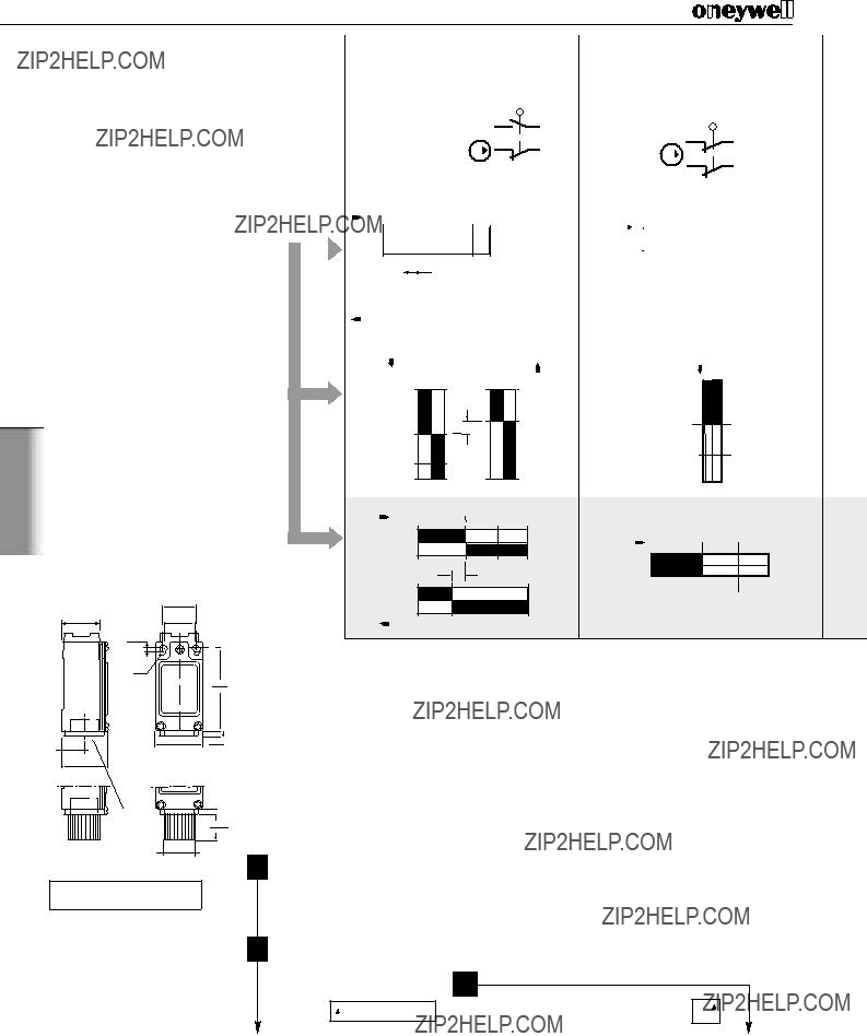
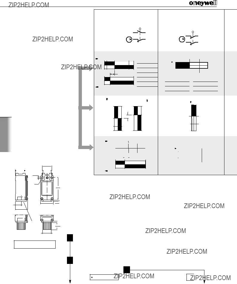
???EN 50041 and EN 50047 mounting and characteristics

???Designed to IEC electrical standard for world-wide use in guarding applications

???Positive opening operation of NC (Normally Closed) contacts conforming to IEC /EN 60947-5-1-3

???Available with a wide range of positive opening contacts

???Rugged housing (Zinc Die-cast)

???Tamper resistant design uses TORX?? head security screw

???Full range of actuator heads and levers suitable for safety applications

???Sealing up to IP 67, NEMA 1, 4, 12 & 13

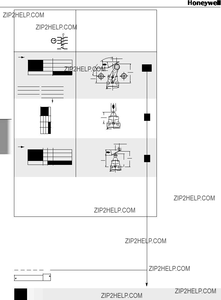
???Snap action and slow action basic switches

???International conduit sizes

???Galvanically isolated contacts

???UL listed; CSA and CE certified, BG approved

???Red body colour for easy safety recognition

BENEFITS

???Standard mounting and characteristics

???Globally available and accepted

???Welded NC contacts will separate ??? vital security in safety applications

???Range of actuation methods for detecting safety conditions in guarding and machine status applications

???Wiring and body flexibility

???Suitable for inductive switching and safety relay interfaces

???Signalling and power/safety circuits may be different polarities or voltages

???Immediately recognisable in the application as a safety component

LOW ENERGY SWITCHING

In today???s demanding age of low energy controls, electromechanical switches are frequently used to interface directly with safety relays, PLCs and other low energy devices. To accommodate this requirement GSS offers gold plated contact versions of the standard basic switch. This improves reliability of switching at low currents and voltages, by protecting the contact surfaces from contamination during opera- tion or storage prior to use.

Standard silver contacts have a disadvantage in that the contact surface may tar- nish under certain environmental conditions e.g. in the presence of moisture.

Low energy basic switches are rated as follows:

! WARNING

MISUSE OF DOCUMENTATION

???The information presented in this product sheet (or catalogue) is for reference only. DO NOT USE this document as system installation information.

???Complete installation, operation and maintenance information is provided in the instructions supplied with each product.

Failure to comply with these instructions could result in death or serious injury.

GSA EN 50041

Safety Metal

Standard

IEC 68-2-27

Terminal marking to EN 50013 *See Standards (page 179)

Dimensions in mm / in

Conduit

Thread

A = 1/2" NPT

C = 20 mm

Ordering:

GSA X

Example: GSA C 01 B

*Point from which the positive opening is assured

**Positive opening occurs at operating position. But to meet IEC/EN 60947-5-3 which requires a dielectric gap of 2,5 kV, positive opening is assured at*.

01

XX

Actuator Types

Side Rotary, metal roller

Top pin plunger

Top roller plunger

47

XXX

Additional Lever Types

For use with all Side Rotary Head Styles.

Figure 1 illustrates standard lever types which conform to EN 50041. All dimensions are in mm / in

GSA

56 /

??19,1 /6,42.2 0.75

0.25

GSS

GSS

R2,15 /

0.08

conduit

thread

19,8 /

0.78

?? 23 /

?? 0.9

Note: Incorporates safety screws

Ordering:

Conduit

Thread

A = 1/2" NPT

C = 20 mm

*Point from which the positive opening is assured

**Positive opening occurs at operating position. But to meet IEC/EN 60947-5-3 which requires a dielectric gap of 2,5 kV, positive opening is assured at*.

Note: See page 197

Actuator Types

Top roller plunger

Additional Lever Types

For use with all Side Rotary Head Styles.

All dimensions are in mm / in

Figure 2 illustrates standard lever types which conform to EN 50047.

GSC

45 /

1.77

40 /

1.586 /

46,5 /

1.83

GSS

XXX

GSS

GSD EN 50047

Safety Double Insulated

Standard

Terminal marking to EN 50013

*See Standards (page 179)

Dimensions in mm / in

22 /

0.87

3 /

0.12

R2,15 /

0.08

conduit thread

19,8 /

0.78Conduit

*Point from which the positive opening is assured

**Positive opening occurs at operating position. But to meet IEC/EN 60947-5-3 which requires a dielectric gap of 2,5 kV, positive opening is assured at*.

?? 23 /

?? 0.9

Thread

A = 1/2" NPT

Note: Incorporates safety screws

C = 20 mm

Ordering:

Low Energy Contacts

Note: See page 197

01

36

Actuator Types

Side Rotary, metal roller

Top pin plunger

Top roller plunger

Additional Lever Types

For use with all Side Rotary Head Styles.

All dimensions are in mm / in

Figure 2 illustrates standard lever types which conform to EN 50047.

GSD

45 /

1.77

40 /

1.586 /

46,5 /

1.83

15 /

0.59

Side Rotary Roller Lever

A1B Metal Roller

Figure 2

GSS

XXX

GSS

GSE EN 50047 Compatible

Safety 3 Conduit Metal

Standard

33 mm *

Top roller plunger

*Point from which the positive opening is assured

**Positive opening occurs at operating position. But to meet IEC/EN 60947-5-3

which requires a dielectric gap of 2,5 kV, positive opening is assured at*.

Example: GSE C 20 B

Additional Lever Types

For use with all Side Rotary Head Styles.

All dimensions are in mm / in

Figure 2 illustrates standard lever types which conform to EN 50047.

GSE

45 /

1.77

40 /

1.586 /

46,5 /

1.83

15 /

0.59

Side Rotary Roller Lever

A1B Metal Roller

Figure 2

GSS

GSS