$'(0&2???9,67$????????????
??????3DUWLWLRQHG???6HFXULW\???6\VWHP???
???
???
3URJUDPPLQJ???*XLGH???
???
???
???
???
???
???
???
???
???
???
???
???
???
???
???
???
???
???
???
???
???
???
???
???
???
???
???
???
???
???
???
???
???
???
???
???
???
???
???
N7001PRV5 5/04 Rev A
Table of Contents
The purpose of this document is to provide a quick and easy way to program your entire system. A recommended programming procedure is included, followed by a list of program fields with the corresponding program group they belong to (system-wide, partition-specific, scheduling, etc.). Two program forms are included. One contains all the programming fields, and the other contains the partition-specific fields. If you are setting up a single-partition system, the partition-specific fields become system-wide fields.
Following the program forms are system layout worksheets. We recommend that you use these sheets to plan your system before programming is performed. If you need further information about specific programming options, see the ADEMCO VISTA-40 Installation and Setup Guide.
Make sure that one two-line alpha keypad is connected to the control and is set to device address "00."
Single-Partition System
The system default is for a single-partition system. Use the VISTA-40 SINGLE PARTITION PROGRAMMING FORM when programming for single-partition usage. Follow the steps outlined in RECOMMENDED PROGRAMMING PROCEDURE of this document for proper programming procedure.
Multiple-Partition System
You must enter the number of partitions you are using in data field 2*00 to set the system for multiple partitions. Use the VISTA-40 SINGLE PARTITION and the PARTITION-SPECIFIC PROGRAM FORMS when programming the system for multiple partitions. Follow the steps outlined in RECOMMENDED PROGRAMMING PROCEDURE of this document for proper programming procedure.
SUMMARY OF PROGRAMMING COMMANDS
???To enter program mode, enter installer code + [8] + [0] + [0]
???To set standard defaults, press ???97
???To change to next page of program fields, press ???94
???To return to previous set of fields, press ???99
???To erase account and phone number field entries, press [???] + field number + [???]
???To assign zone descriptors, press #93 + follow menu prompts
???To add custom words, press #93 + follow menu prompts
???To enter Installer's Message, press #93 + follow menu prompts
???To exit program mode, enter ???99 OR ???98: ???99 allows re-access to programming mode by installer code. ???98 prevents re-access to programming mode by installer code.
Standard default (???97) values are shown in brackets [ ], otherwise default = 0.
??? 2 ???
Recommended Programming Procedure
The following is a step-by-step procedure recommended for programming your VISTA-40 system.
1.Set the keypads (and other peripheral devices) to the appropriate addresses.
2.Set factory defaults by pressing ???97.
This will automatically enable keypad addresses 00-01, so be sure at least one keypad is set to one of these addresses.
3.Program system-wide (global) data fields.
Using the programming form as a guide, enter program mode and program all system-wide programming fields. These options affect the entire system, regardless of partitions. They include control options, downloader and dialer options, RF options, event logging options, etc. Refer to the Program Field Index for a listing of the program fields and their function.
Note that field 2???00 (number of partitions) must be programmed before continuing.
4.Program partition-specific fields.
When the system-wide fields have been programmed, program all partition-specific programming fields by first pressing ???91 to select a partition (while still in data field program mode). Then enter the first partition- specific field number ???09. When you are finished, the next partition-specific field is automatically displayed. Partition-specific fields can have different values for each partition. To program the fields for the next partition, press ???91, enter the desired partition number, then enter field ???09. Refer to the MECHANICS OF PROGRAMMING section in the ADEMCO VISTA-40 Installation and Setup Guide for detailed instructions.
5.Use #93 Menu Mode for device programming.
Refer to Device Programming in this guide to assign keypad ID numbers and default partitions for each keypad, and to selectively suppress certain keypad sounding options. Also use this mode to assign RF receivers, relay modules, and the VIP module.
6.Use #93 Menu Mode for zone programming.
Refer to Zone Programming in this guide to program zone response types, assign right loop zones and wireless zones, assign zones to partitions, and to program alarm report codes.
7.Use #93 Menu Mode for programming relays.
Refer to Relay Programming in this guide to program desired relay operation.
8.Program Communication options.
Refer to System Communication section in the ADEMCO VISTA-40 Installation and Setup Guide for detailed instructions. Then use #93 menu mode to program report codes.
9.Use #93 Menu Mode for programming alpha descriptors.
Refer to Alpha Programming in this guide to enter zone and partition descriptors and a custom installer???s message.
10.Use #93 Menu Mode for relay voice descriptors and custom word substitutes.
Refer to Relay Voice Descriptors in this guide for further instructions for programming relay descriptors to be annunciated by the VIP module, as well as the Custom Index section for custom word substitutes.
11.Define user access codes.
Refer to User Access Codes in the ADEMCO VISTA-40 Installation and Setup Guide to program authority level, O/C reporting option, partition assignments, and RF key assignments for each user.
12.Exit Programming Mode.
Exit programming mode by pressing either ???98 or ???99. Additional entries of ???99 are required if the exit is being done from fields 1???00 and above.
To prevent re-access to programming mode using the Installer???s code, use ???98. The only way to re-access programming mode is by depressing both the [???] and [#] keys at the same time within 30 seconds of power- up.
Exiting by using ???99 always allows reentry into programming mode using the Installer code. Either way of exiting allows access via downloading. Note that if local programming lockout is set via downloading, programming mode cannot be entered at the keypad.
??? 3 ???
Program Field Index
On the following pages, the programming fields have been arranged in numerical order. Use this index to cross-reference the fields on the programming form.
??? 4 ???
VISTA-40 Programming Form
Some fields are programmed for each partition (shown as shaded fields). If you are programming a multiple-partition system, see the Partition-Specific Fields section for programming these fields. Standard default (*97) values are shown in brackets.
Enter 00-09; B-F (11-15) [15 15 15 15]
*33 PRIMARY PHONE NUMBER
Enter 1 for fast response time 10ms Enter 0 for normal response time 350ms. Must be 0 for UL installations.
1=10-40 min; 0=normal report (about 2 min. after AC loss).
Enter 0-9 for each digit. Enter #11 for *, #12 for #, #13 for 2 second pause
*34 SECONDARY PHONE NUMBER
Enter 0-9 for each digit. Enter #11 for *, #12 for #, #13 for 2 second pause
*35 DOWNLOAD PHONE NO.
1=Ignore; 0=Enable tamper for RF and RPMs.
Must be "0" for UL installations if using these devices.
Enter 0-9 for each digit. Enter #11 for *, #12 for #, #13 for 2 second pause
*36 DOWNLOAD ID NO.
Enter 00-09; A-F (10-15) [15 15 15 15 15 15 15 15]
*37 DOWNLOAD COMMAND ENABLES
0
Dlr ShtdwnSys ShtdwnNot UsedRmt BypRmt DisarmRmt ArmUpld PgmDwnld Pgm
See field 1*53 for Callback disable option; [1=enable]; 0=disable. For UL installations, all entries must be "0."
01-64; 00 if all zones can be bypassed

1=yes; 0=no If used with Spilt Reporting "1" option (1*34), alarms and alarm restores go to both primary & secondary numbers, while all other reports go to secondary only. If used with Split Reporting "2" option, alarms and alarm restores go to both, open/close and test messages go to secondary only, while all other reports go to primary.
*52 STANDARD/EXPANDED REPORT FOR PRIMARY
[0 0 0 0 0 0]
Alarm Rstr Byp Trbl O/C LoBat
0=standard; 1=expanded;
Note: Expanded overrides 4+2 format.
*53 STANDARD/EXPANDED REPORT FOR SECONDARY
[0 0 0 0 0 0]
Alarm Rstr Byp Trbl O/C LoBat
0=standard; 1=expanded;
Note: Expanded overrides 4+2 format.
*54 *57 ALARM REPORT CODES & ID DIGITS FOR ZONES 01-16.
Skip these fields. Use #93 Menu Mode, Zone
Programming to program the report codes.
*58 SUPERVISORY AND RESTORE CODES FOR ZONES 01-16. Enter 00-09; B-F (11-15). Default = [00 00 00 00 00]
*59 *62 ALARM REPORT CODES & ID DIGITS FOR ZONES 17-32.
Skip these fields. Use #93 Menu Mode, Zone
Programming to program the report codes.
*63 SUPERVISORY AND RESTORE CODES FOR ZONES 17-32. Enter 00-09; B-F (11-15). Default = [00 00 00 00 00]
*64 *67 ALARM REPORT CODES & ID DIGITS FOR ZONES 33-48.
Skip these fields. Use #93 Menu Mode, Zone
Programming to program the report codes.
*68 SUPERVISORY AND RESTORE CODES FOR ZONES 33-48. Enter 00-09; B-F (11-15). Default = [00 00 00 00 00]
*69 *72 ALARM REPORT CODES & ID DIGITS FOR ZONES 49-64.
Skip these fields. Use #93 Menu Mode, Zone
Programming to program the report codes.
*73 SUPERVISORY AND RESTORE CODES FOR ZONES 49-64. Enter 00-09; B-F (11-15). Default = [00 00 00 00 00]
*74 *77 ALARM REPORT CODES & ID DIGITS FOR ZONES 87-99.
Skip these fields. Use #93 Menu Mode, Zone
Programming to program the report codes.
*78 SUPERVISORY AND RESTORE CODES FOR ZONES 87-99. Enter 00-09; B-F (11-15). Default = [00 00 00 00 00]
[Day 00; hour 12; min 00] Days 01-07 Hours 00-23 Min 00- 59; 00 in all boxes = instant (Day 01= Monday)
01-15 alarms
Must be "00" (disabled) for UL.
*85 ENABLE DIALER REPORTS FOR PANICS & DURESS
1=enable; [0=disable]
995 996 999 Duress
1 = allows 8 zones on one module (10-17), but prevents any other polling loop expansion. 0 = all other setups.
MISCELLANEOUS WIRELESS OPTIONS
Fields 1*28 - 1*31 are not applicable for UL installations.
Enter 0 for ground start output. Enter 1 for open/close trigger. Enter 2 for keypad-like sounding. Enter 3 if AAV module is being used.
NOTE: Only one of the above options may be active within the system.
Enter "1" to enable. If a zone is faulted after pressing button, keypad will beep once. Pressing the button again within 4 sec. bypasses the zone. Enter "0" to disable.
Must be "0" for UL installations.
1*60 ZONE 5 AUDIO ALARM VERIFICATION [0]
Enter 1 If 2-way audio (AAV) is being used; Enter 0 if it is not.
Must be "0" for UL installations.
Enter 1 to alarm sounders during AAV session.
Enter 0 to have alarm sounders continue to sound during AAV session. Must be 0 for UL installations.
1*70 EVENT LOG TYPES
[1 0 0 0 1]
Alarm Chk Byp O/C Syst
1=enable; 0=disable
Enter the relay timeout, 000-127 seconds for #93 Menu Mode Relay Programming command "57."
Relay will be pulsed for 2 seconds whenever code + [0] is pressed. Enter 00-08; 00=none.
Must be "00" for UL.
3rd Page Programming Fields (press *94)
SUMMARY OF PROGRAMMING COMMANDS
???To enter program mode, enter installer code + [8] + [0] + [0]
???To set standard defaults, press *97
???To change to next page of program fields, press *94
???To return to previous set of fields, press *99
???To erase account and phone number field entries, press [*] + field number + [*]
???To assign zone descriptors, press #93 + follow menu prompts
???To add custom words, press #93 + follow menu prompts
???To enter Installer's Message, press #93 + follow menu prompts
???To exit program mode, enter *99 OR *98: *99 allows re- access to programming mode by installer code. *98 prevents re-access to programming mode by installer code.
Partition-Specific Fields
(Duplicate this page for each partition in the installation.) To program these fields,
1.Press *91 to select a partition.
2.Enter a partition-specific field number (ex. *09).
3.Make the required entry.
4.Repeat steps 1-3 for the other partition in the system.
PARTITION #____ PROGRAM FIELDS
00, 03-15 times 15 seconds.
Maximum 04 for UL Listed installations.
1=yes; 0=no. Must be 1 for UL installations.
Relay will be pulsed for 2 seconds whenever code + [0] is pressed. Enter 00-08; 00=none. Must be "00" for UL installs.
3rd Page Fields
1=Allow log-on from other partitions; 0=disable
01-15 alarms; Must be "00" (disabled) for UL installations.
*85 ENABLE DIALER REPORTS FOR PANICS & DURESS
1=enable; [0=disable]
995 996 999 Duress
1=continuous; 0=3 beeps
SUMMARY OF PROGRAMMING COMMANDS
???To enter program mode, enter installer code + [8] + [0] + [0]
???To set standard defaults, press *97
???To change to next page of program fields, press *94
???To return to previous set of fields, press *99
???To erase account and phone number field entries, press [*] + field number + [*]
???To assign zone descriptors, press #93 + follow menu prompts
???To add custom words, press #93 + follow menu prompts
???To enter Installer's Message, press #93 + follow menu prompts
???To exit program mode, enter *99 OR *98: *99 allows re- access to programming mode by installer code. *98 prevents re-access to programming mode by installer code.
Programming With #93 Menu Mode
NOTE: The following field should be preset before beginning: 2*00 Number of Partitions. In addition, receivers should be programmed via Device programming.
After programming all system related programming fields in the usual way, press #93 while still in programming mode to display the first choice of the menu driven programming functions. Press 0 (NO) or 1 (YES) in response to the displayed menu selection. Pressing 0 will display the next choice in sequence.
#93 MENU MODE KEY COMMANDS
The following is a list of commands used while in the menu mode. #93 Enters Menu mode
[4] Serves as ENTER key. Press to have keypad accept entry. [#] Backs up to previous screen.
0Press to answer NO
1Press to answer YES
01-09 All data entries are either 1-digit or 2-digit entries.
00 Exits menu mode, back into field programming mode, when entered at the first question for each category.
Menu selections are as follows:
??? Partition Number for Zone
??? Dialer report code for zone
??? Input Device Type for zone (whether RF, polling loop, etc.)
??? Enrolling serial numbers of 5800 Series transmitters & serial polling loop devices into the system.
Same as Zone Programming except:
???Done with a minimum number of keystrokes.
???Can program wireless keys using pre-defined templates.
For entering alpha descriptors for the following:
???Zone Descriptors
???Installer's Message
???Custom Words
???Partition Descriptors
???Relay Descriptors
For defining relay functions.
For entering voice descriptors for relays to be used with the 4285/4286 VIP Module.
For creating custom word substitutes for VIP Module annunciation.
If using 5800 Series transmitters, do not the install batteries until you are ready to enroll them. After enrolling the transmitter, the battery need not be removed. This is to prevent enrolling the wrong serial number.
SET TO CONFIRM?
10 ZONE TYPE
PERIMETER03
Zone number 10 and Zone Type 03 entry shown
??? These are special zone types used with 5800 Series Wireless Pushbutton Units that result in arming the system in the STAY or AWAY mode, or disarming the system, depending on the selection made.
This prompt appears once upon entering Zone Programming Mode.
If ???Yes,??? Confirmation prompts will be displayed after the device???s Serial and Loop numbers have been entered later.
Enter the 2-digit zone number to be programmed, as follows:
Protection Zones = 01???64
System Supervisory Zones = 88, 89, 90, 91, 92 (duress), 97
Keypad Panic Zones = 95, 96, 99
Press [???] to continue.
This display appears, showing a summary of the zone's current programming. ZT = Zone Type, P = Partition, RC = Report Code, In = the input type of device, and L = the device's loop number to which the sensor is connected.
Some devices can support more than one zone by means of individual loops (for example, 5801, 5804, 5816, 5817, etc.). If the zone is not programmed, the display appears as shown here. If you are checking a zone's programming, and it is programmed satisfactorily, press [#] to back up one step and enter another zone number, if desired.
Press [???] to continue.
Each zone must be assigned a zone type, which defines the way in which the system responds to faults in that zone. Refer to the Zone Type Definitions section in the ADEMCO VISTA-40 Installation and Setup Guide for detailed definitions of each zone type. Enter the zone type desired (or change it, if necessary). Available zone types are listed below.
Press [???] to continue.

Input types 4 & 5 are valid for certain 5800 Series transmitters only (e.g., 5801, 5802, 5802CP & 5803).
Enter the input device type as follows: 00 = not used
01 = hardwired
03 = supervised RF transmitter (RF type)
04 = unsupervised RF transmitter (UR type)
05 = RF button-type transmitter (BR type)
06 = serial number polling loop device (SL type)
07 = DIP switch-type polling loop device
08 = right loop of DIP switch type device
Right loops refer to the use of the right loop on a 4190WH Zone Expander Module and/or 4278 PIR, which allow hardwired devices to be monitored by the polling loop.
If you are programming hardwired or DIP switch polling loop devices, the summary display appears after completing this entry.
Press [???] to continue.
For Serial Number entry and Loop Number entry, do one of the following:
a.Transmit two open and close (or close and open) sequences. For a button-type transmitter, press and release the button, wait approximately 4 seconds, then press and release the button a second time.
OR
b.Manually enter the 7-digit serial number printed on a label on the transmitter, using the Alpha keypad. Then press the [???] key, the cursor moves to the ???L??? position. You can edit the loop number, if necessary. When the loop number is acceptable, press [???].
OR
c.Press key [C] to copy the last serial number enrolled (used when programming a transmitter with several input loops).
Press [???] to accept.
The cursor will then move to the Loop column (L) with the previously entered/transmitted serial number displayed.
Enter the loop number (refer to 5800 Series Transmitters Loop Designations below).
To Delete an Existing Serial Number, enter 0 in the loop number field. The serial number will change to ???0???s.
If 0 was entered in error, simply re-enter the loop number or press [#], and the serial number will return to the display.
Press [???] to accept.
The system will then check for a duplicate serial/loop number combination.
If a duplicate serial/loop number combination is found, the keypad will emit a single long beep, and display the serial number along with a ??????? for the loop number, allowing you to re-enter the correct loop number.
If the serial/loop number combination is not a duplicate in the system, a display appears showing the serial number and loop number entry.
Press [???] to continue.
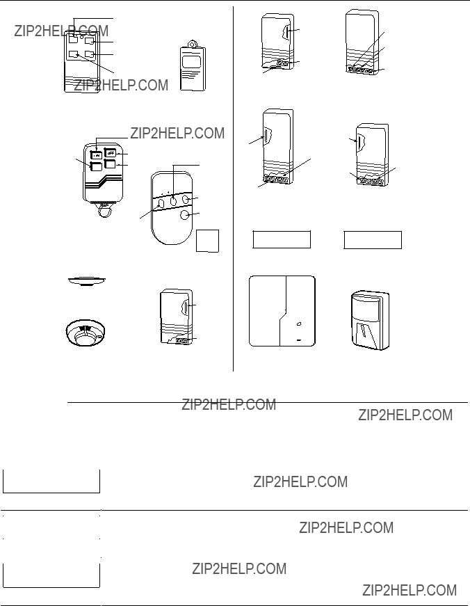
5800 Series Transmitters Loop Designations
CODE
5804BD
ENROLL AS "BR"
 LOOP
LOOP  1
1
5809
ENROLL AS "RF"
LOOP 1 (MOTION)
 (Green)
 (Red) (Yellow)
5800_trans_loop-V0
Note: For information on any transmitter not shown above, refer to the instructions accompanying that transmitter for details regarding loop numbers, etc.
XMIT TO CONFIRM
PRESS ???TO SKIP
Confirmation Option: This prompt only appears if you answered ???Yes??? at the first prompt. The system enters a confirmation mode so that the operation of the actual programmed input can be confirmed. Activate the loop input or button that corresponds to this zone. At any time during this step, you may press the [???] key on the keypad to save the serial and loop number combination without confirming.
10 ZT P RC In L
03 1 3C RF 1s
If the serial number transmitted does match the serial number entered, the system beeps 3 times and a summary display appears, showing that zone???s programming. Note that an ???s??? indicates that a transmitter???s serial number has been enrolled.
Press [???] to accept the zone information.

After you have enrolled each wireless device, remove ONE of the serial number labels from that device and affix it in the appropriate column on the worksheets provided later in this Programming Guide; then enter the other information (zone number, zone type, etc.) relevant to that device.
When you have finished programming all zones, test each using the system???s Test Mode. Do not use the Transmitter ID Sniffer Mode. The system checks only for transmission of one zone on a particular transmitter, NOT the zones assigned to each additional loop, and also does not verify polling loop type zones.
Expert Mode Zone Programming
Expert mode allows you to program zones using the minimum number of screens and keystrokes. Enter the Programming mode with [Installer Code] + [8] [0] [0]
Before programming your zones, do the following:
1.Program field 2???00: Number of Partitions.
2.Enable your RF Receiver in Device Programming menu mode.
To program your zones, press ???93 to display the "ZONE PROG?" prompt. Enter 0 (NO) to each prompt until the ???EXPERT MODE???? prompt appears.
Press 1 to enter Expert mode.
This prompt appears once upon entering Expert Mode.
If you select ???Yes,??? Confirmation prompts will be displayed after the device???s Serial and Loop numbers have been entered later.
A summary display appears, showing zone 1???s current programming or default values.
Enter the desired 2-digit zone number and press [???]. Note: If you want to exit the Expert mode, enter 00 + [???].
If an ???s??? appears after the loop number, it indicates that the transmitter???s serial number has been enrolled. Use the [D] key to enter and duplicate wireless keys (see ???Entering Wireless Keys??? later)
Enter all zone information except for Loop number, or press [C] to copy the zone information on this screen from the last saved zone (including Loop).
ZT = Zone Type P = Partition
RC = Report Code
In = Input Device Type
L = Loop number to which the sensor is connected.
NOTE: Pressing the [C] copies the zone information from the last saved zone, which includes the input type. Verify this information is correct for this zone.
On this screen:
???Use the [A] key to move to the right.
???Use the [B] key to move to left and to back up to ???ZT??? field. Press [???] to accept the existing or newly entered zone information.
??? 14 ???
EXPLANATION
If you entered RF, BR, UR or SL for the Input Type, this screen displays. Otherwise the summary screen for the next zone displays.
Enter the 7-digit serial number, using one of the following methods:
a.Transmit two open and close (or close and open) sequences. For a button-type transmitter, press and release the button, wait approximately 4 seconds, then press and release the button a second time.
OR
b.Manually enter the 7-digit serial number printed on a label on the transmitter, using the alpha keypad. Then press the [???] key, the cursor will move to the ???L??? position. You can edit the loop number, if necessary. When the loop number is acceptable, press [???].
OR
c.Press key [C] to copy the last serial number enrolled (used when programming a transmitter with several input loops).
Remember, you can use the [A] key to move to the right or the [B] key to move to the left. You can also use the [#] key to back up without saving.
Press [???] to accept the serial number and advance to the ???L??? position (if method ???a??? or ???c??? was used), then enter the loop number.
If necessary, press the [#] key to back up without saving, and re-enter or edit the serial number before pressing [???] to save
The system checks for a duplicate. If a duplicate serial/loop number combination is found, the keypad will emit a single long beep, and display the serial number along with a ??????? for the loop number, allowing you to re-enter the correct loop number.
XMIT TO CONFIRM
PRESS ???TO SKIP
To Delete an Existing Serial Number, enter 0 in the loop number field. The serial number will change to ???0???s.
If 0 was entered in error, simply re-enter the loop number or press [#], and the serial number will return to the display.
The prompt to confirm appears. This prompt only appears if you answered ???Yes??? at the ???SET TO CONFIRM???? prompt.
The system enters a confirmation mode so that the operation of the actual programmed input can be confirmed. Activate the loop input or button that corresponds to this zone. At any time during this step, you may press the [???] key on the keypad to save the serial and loop number combination without confirming.
If the serial number transmitted matches the serial number entered, the system beeps 3 times and advances to the summary display for the next zone's programming.
After all the zones have been programmed, enter 00 for the zone number to quit.
After you have enrolled each wireless device, remove ONE of the serial number labels from that device and affix it in the appropriate column on the worksheets provided later in this Programming Guide; then enter the other information (zone number, zone type, etc.) relevant to that device.
Entering Wireless Keys
If you pressed the D key previously to enter defaults for 5804 and/or 5804BD wireless keys, the following screens appear:
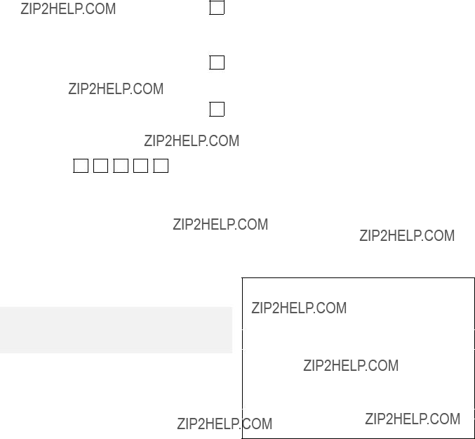
Enter template number (1???6).
1???3 = 5804 templates; 4???6 = 5804BD templates. See the defaults provided for each template in the chart that follows these procedures.
Select from templates. Press [???] to display template (template 1 shown selected). Note: If necessary, press [#] to back up and re-enter template number.
Press [#] if you want to return to zone attributes screen.
When you press [???], the selected template is displayed.
Top line of display represents loop numbers; bottom line represents zone type.
Press [???] to accept template.
???If that zone number is displayed, the system has the required number of consecutive zones available,
Example of zone number suggested by the system. This indicates that zones 24, 25, 26, and 27 are available.
beginning with the zone you entered. If not, the system again displays a suggested zone that can be used. If the required number of consecutive zones is not available at all, the system will display ???00.???
Press [???] to accept.
To enter the serial number:
Press and release a button on the wireless key.
OR
Manually enter the 7-digit serial number printed on the device???s label. Press [???] to accept serial number. The system checks for a duplicate.
If a duplicate exists, a long error beep will sound and the serial number reverts back to all ???X???s allowing you to re-enter the serial number.
Use the [A] key to move forward within the screen, and the [B] key to back up.
XMIT TO CONFIRM
PRESS ???TO SKIP
Entd A022-4063
Rcvd A022-4064
If you entered YES previously at the SET TO CONFIRM prompt (see first prompt following entry into the Expert Programming Mode), the display on the left appears.
To confirm, activate the button on the wireless key that corresponds to this zone.
If the serial number transmitted does not match the serial number entered, a display similar to the one at the left appears.
If so, activate the loop input or button on the transmitter once again. If a match is not obtained (i.e., summary display does not appear), press the [#] key and then enter the correct serial number.
Activate the button on the wireless key again after re-entering the serial number.
After you have enrolled each wireless device, remove ONE of the serial number labels from that device and affix it in the appropriate column on the worksheets provided later in this Programming Guide; then enter the other information (zone number, zone type, etc.) relevant to that device.
??? 16 ???
Alpha Descriptors Programming
You can program a user-friendly English language description/location for all protection zones, relays, keypad panics, polling loop short, and RF receiver supervision troubles.
Each description can be composed of a combination of words (up to 3) that are selected from a vocabulary of 244 words stored in memory, and any word can have an "s" or " ???s " added to it. In addition, up to 20 installer-defined words can be added to those already in memory. Thus, when an alarm or trouble occurs in a zone, an appropriate description for the location of that zone will be displayed at the keypad.
NOTE: Due to the use of 2-digit zone numbers, the first word of the descriptor is limited to 7 characters if you want it to fit on the top line of the display.
A custom installer???s message can be programmed for each partition, which is displayed when the system is "Ready" (e.g., THE PETERSONS???).
1.To program alpha descriptors, enter Programming mode, then press [#]93 to display "ZONE PROG?"
2.Press 0 (NO) twice to display "ALPHA PROG?".
3.Press 1 to enter Alpha Programming.
There are 5 submenu selections that will be displayed one at a time.
Press 1 to select the mode desired. Press 0 to display the next mode available. The alpha menu selections are:
4.Refer to the sections that follow for procedures for adding alpha descriptors.
Zone Descriptors
1.Select ZONE DESCRIPTOR mode.
The keypad keys perform the following functions:
[3] Scrolls both alphabet and actual words in ascending alphabetical order.
[1]Scrolls both alphabet and actual words in descending alphabetical order.
[2]Adds or removes an "s" or " 's " to a vocabulary word.
[6] Switches between alphabet and actual word list; used to accept entries. [8] Saves the zone description in the system's memory.
[#][#] plus zone number displays the description for that zone.
2.Enter the zone number to which you want to assign a descriptor.
For example, key [???] 01 to begin entering the description for Zone 1, (key [???] 02 for Zone 2, [???] 03 for Zone 3, etc.). The following is displayed: ??? ZN 01 A.
Note that the first letter of the alphabet appears after the zone number, and that the zone number is automatically included with the description.
3.Enter the descriptor for that zone. Use one of two methods as follows:
(Assume, for example, that the desired description for Zone 1 is BACK DOOR.)
a)Press [#] followed by the 3-digit number of the first word from the fixed dictionary shown later in this section (e.g., [0][1][3] for BACK).
Press 6 in order to accept the word and proceed, or press 8 to store the complete descriptor and exit; or
b)Select the first letter of the desired description (note that "A" is already displayed). Use the 3 key to advance through the alphabet and the 1 key to go backward.
Press 3 key repeatedly until "B" appears (press 1 to go backwards if you happen to pass it), then press 6 to display the first available word beginning with ???B???.
Press 3 repeatedly to advance through the available words until the word ???BACK??? is displayed.
To add an "s" or " 's" if you need to, press 2. The first depression adds an "s," the second depression adds an " 's, " the third depression displays no character (erases the " 's"), the fourth depression adds an "s," etc.
??? 17 ???
4.Accept the word.
To accept the word, press 6, which switches back to the alphabet list for the next word, or press 8 to store the complete descriptor and then exit.
5.Select the next word.
For selection of the next word (DOOR), repeat step 3a (word #057) or 3b, but selecting the word "DOOR.??? To accept the word, press 6, which again switches back to alphabet list.
6.Store the descriptor.
When all desired words have been entered, press 8 to store the description in memory. To review the zone descriptors, key [#] plus zone number (e.g., #01).
To edit zone descriptors, key [???] plus zone number (e.g., ???01)
7.Exit Zone Description Mode: enter 00.
Default Screen (Custom Message Display)
Normally, when the system is in the disarmed state, the following display is present on the keypad.
****DISARMED****
READY TO ARM
Part or all of the above message can be modified to create a custom installer message for each partition. For example, ???****DISARMED****??? on the first line or ???READY TO ARM??? on the second line could be replaced by the installation company name or phone number for service.
Note: There are only 16 character spaces on each of the two lines. To create a custom display message, proceed as follows:
1.Select Default Screen mode.
The keypad asks for the partition number for this message. Enter the partition number. Press [???] to accept entry.
The following display appears:
****DISARMED****
READY TO ARM
A cursor is present at the extreme left of the first line (over the first "star"). Press 6 to move the cursor to the right and 4 to move the cursor to the left. Press 7 to insert spaces or erase existing characters.
2.Create the message.
For example, to replace ???READY TO ARM??? with the message ???SERVICE 424-0177,??? proceed as follows:
Press 6 to move the cursor to the right, and continue until the cursor is positioned over the first location on the second line.
Press 3 to advance through the alphabet to the first desired character (in this case, "S"). Press 1 to go backward, when necessary. When the desired character is reached, press 6.
The cursor then moves to the next position, ready for entry of the next character (in this example, "E"). When the cursor reaches a position over an existing character, press 3 or 1 to advance or back up from that character in the alphabet. Proceed in this manner until all characters in the message have been entered.
3.Save the message.
Store the new display message in memory by pressing 8.
4.The system asks for a new partition number.
Enter 0 to quit or 1-2 for a new partition number.
Custom Words
Up to 20 installer-defined words can be added to the built-in vocabulary. Each of the 20 "words" can actually consist of several words, but bear in mind that a maximum of 10 characters can be used for each word string.
1.Select CUSTOM WORD Mode.
The keys perform the following functions:
[3] Advances through alphabet in ascending order.
[1] Advances through alphabet in descending order.
[6] Selects desired letter; moves the cursor 1 space to the right. [4] Moves the cursor one space to the left.
[7]Inserts a space at the cursor location, erasing any character at that location.
[8]Saves the new word in the system's memory.
[???] Returns to Description Entry Mode.
??? 18 ???
2.Enter the custom word number (01-20) you want to create.
For example, if you are creating the first word (or word string), enter 01; when creating the second word, enter 02, and so on. A cursor now appears at the beginning of the second line.
3.Type the word using one of two methods as follows:
a)Press [#], followed by the 2-digit entry for the first letter you would like to display (e.g., 65 for "A").
When the desired character appears, press 6 to select it. The cursor will then move to the right, in position for the next character. Press [#] plus the 2-digit entry for the next letter of the word.
or
b)Press 3 to advance through the list of symbols, numbers, and letters. Press 1 to move back through the list.
When you have reached the desired character, press 6 to select it. The cursor then moves to the right, in position for the next character.
4.Repeat step 3 to create the desired custom word (or words).
Press 4 to move the cursor to the left if necessary.
Press 7 to enter a blank (or to erase an existing character). Each word or word string cannot exceed 10 characters.
5.Save the word by pressing 8.
This returns you to the ???CUSTOM WORD???? display. The custom word (or string of words) is automatically added to the built-in vocabulary at the end of the group of words beginning with the same letter.
Custom words are retrieved as word numbers 250 to 269 for words 1 to 20, respectively, when using method 3a to enter alpha descriptors.
When using method 3b to enter alpha descriptors, each word appears at the end of the group of words that begin with the same letter as it does.
6.Repeat steps 2 through 6 to create up to a maximum of 20 custom words (or word strings).
7.Exit Custom Word Mode by entering 00 at the ???CUSTOM WORD??? prompt.
Partition Descriptors
1.Select "Part DESCRIPT." Mode.
The system asks for the partition number desired. Enter the number as a single-key entry 1-2.
2.Follow the same procedure as for custom words.
Note: The partition descriptors are limited to 4 characters (e.g., WHSE for warehouse).
??? 19 ???
Alpha Descriptor Vocabulary
(For entering alpha descriptors. To select a word, press [#] followed by the word???s 3-digit number.)
NOTE: This vocabulary is not to be used for relay voice descriptors. See the Relay Voice Descriptors section when
programming relay voice descriptors.
CHARACTER (ASCII) CHART
Notes: This factory-provided vocabulary of words is subject to change.
Bulleted words in bold face type are those that are also available for use by the 4285/4286 VIP Module. If you are using a VIP Module, and words other than these are selected for alpha descriptors, the Voice Module will not provide annunciation of those words.
??? 20 ???
Device Programming
This menu is used to program keypads, receivers, and relay modules, etc.
Device Address 00 is always set as an alpha keypad assigned to Partition 1 with no sounder suppression options, and these settings cannot be changed.
From Data Field Programming mode, press [#]93 to display "ZONE PROG?" Press 0 repeatedly to display "DEVICE PROG?"
Press 1 to enter Device Programming.
The device address identifies the device to the control. Enter the 2-digit device address number to match the device???s physical address setting (01-15).
NOTE: If using the 4285/4286 Voice Module, it must be used at Device Address 04.
Select the type of addressable device as follows:
Press [???] to accept entry.
01 CONSOLE PART.
1
01 SOUND OPTION
00
If you selected device type 1 (alpha keypad) or 2 (fixed keypad), this prompt appears. Enter the addressable device???s default partition number (1 to maximum number of partitions programmed for system in field 2*00). This is the primary partition for the device.
Press [???] to accept entry.
Keypads can be individually programmed to suppress arm/disarm beeps, entry/exit beeps and chime mode beeps. This helps prevent unwanted sounds from disturbing users in other areas of the premises.
Enter a number 00-03 for the keypad sounding suppression options desired for the keypad as follows: 00 = no suppression
01 = suppress arm/disarm & entry/exit beeps
02 = suppress chime mode beeps only
03 = suppress arm/disarm, entry/exit and chime mode beeps Press [???] to accept entry.

The system supports up to 8 relay outputs. Relays can be used to perform many different functions and actions. Each relay must be programmed to begin one of three types of ACTIONS at a designated START event, and end that ACTION at a designated STOP event. The options and prompts used to start and stop these devices are described below
The letter(s) in parentheses after each function described below, such as (A) after ACTION, are those that appear in the various summary displays of programmed data during programming.
ACTION (A) The "ACTION" of the device is how the device will respond when it is activated by the "START" programming. You may want the device to activate momentarily, to pulse on and off continuously, or to remain activated until some other event occurs to stop it. There are five different action choices:
???ACTIVATE for 2 SECONDS and then reset.
???ACTIVATE and REMAIN ACTIVATED until stopped by some other event.
???PULSE ON and OFF until stopped by some other event.
???NO RESPONSE when the device is not used.
START (STT) The "START" programming determines when and under what conditions the device is activated. The following START options are available:
1)EVENT (EV) is the condition (alarm, fault, trouble) that must occur to a zone or group of zones (zone list) in order to activate the device. These conditions apply only when a zone list is used. The different choices for "EVENT" are listed below and in ???Programming Relays??? later in this section.
ZONE LIST (ZL) is a group of zones to which the ???EVENT??? applies in order to activate a particular device. Note that there are a total of 4 zone lists that can be programmed; when the selected EVENT (alarm, fault or trouble) occurs in any zone in the selected ???Start??? ZONE LIST (1-4), activation of the selected device will START.
3)ZONE TYPE/SYSTEM OPERATION (ZT). If all zones to be used to start the device have the same response type, and there are no other zones of this type that are not to activate this device, then ???ZONE TYPE??? may be used instead of a "ZONE LIST" and "EVENT??? to activate the device.
If a system operation, such as ???DISARMING??? or ???ANY FIRE ALARM,??? is to activate the device, enter the appropriate choice under the ???ZONE TYPE??? option.
The ???ZONE TYPE/SYSTEM OPERATION??? option functions independently of the ???EVENT/ZONE LIST??? combination.
If a specific "ZONE TYPE" is chosen, any zone of that response type going into alarm, trouble, or fault will cause the device to activate as selected in "ACTION.??? If the same ???ZONE TYPE??? is also chosen for the STOP programming, any zone of that type that restores will de-activate the device.
If a "SYSTEM OPERATION" is chosen, that operation will cause the device to activate as selected in "ACTION.??? The different choices for "ZONE TYPE" and "SYSTEM OPERATION" are listed in ???Programming Relays??? later in this section, and on the Programming Form.
4)PARTITION NO. (P). The device's "Start" ZONE TYPE/SYSTEM OPERATION may be limited to an occurrence on one partition (1-2), or any partition (0).
STOP (STP): The "STOP" programming determines when and under what conditions the device is de-activated. The following options are available:
1). RESTORE ZONE LIST (ZL). If a "ZONE LIST" is used as the ???Stop??? event, the device de-activates when all the zones in that list restore from a previous fault, trouble, or alarm condition. This occurs regardless of what is programmed to "START" the device; therefore, a "RESTORE ZONE LIST" is normally only used when a "ZONE LIST" is used to start the device.
2). ZONE TYPE/SYSTEM OPERATION (ZT). Instead of using a "RESTORE ZONE LIST," you can select a specific zone (response) type or system operation action to de-activate the device.
If you choose a specific "ZONE TYPE," any zone of that response type that restores from a previous alarm, trouble, or fault condition will cause the device to de-activate.
If you choose a "SYSTEM OPERATION," that operation causes the device to de-activate. The different choices for "ZONE TYPE" and "SYSTEM OPERATION" are listed in ???Programming Relays??? later in this section, and in the Programming Form.
3)PARTITION NO. (P). The device's "Stop" Zone Type/System Operation may be limited to an occurrence on one partition (1-2), or on any partition (0).
The ???ZONE TYPE/SYSTEM OPERATION??? option functions independently of the ???RESTORE/ZONE LIST??? combination.
???22 ???
Relay Output Devices Programming
From Data Field Programming Mode, press #93 to display the "ZONE PROG?" prompt. Press [0] (NO) to each menu option until the "RELAY PROG?" prompt appears. Press [1] (YES).
While in this mode, press [???] to advance to next screen. Press [#] to back up to the previous screen.
Enter the relay (output device) identification number 01-08. This is a reference number only, used for identification purposes. The actual module address and relay number on the module are programmed in the last two prompts.
Press [???] to continue.
Press [???] to continue.
The keypad displays a summary STOP screen.
Press [???] to continue.
The Relay Action is the way in which the relay will respond when activated by the "start" event. Enter the desired action for this relay as follows:
0=not used; 1=close for 2 secs.; 2=stay closed; 3=pulse on/off
A relay may be activated by an Event/Zone List combination, and/or by a Zone Type/System Operation. For an Event/Zone List combination, enter the event code as follows:
0=not used; 1=alarm; 2=fault; 3=trouble
If you are not using a Zone List to activate the relay, enter 0. Press [???] to continue.
A zone list is a set of zones that can be used to initiate the start or stop relay action. If a zone list is being used to start this relay action, enter the zone list number, 1-4. If a zone list is not being used, enter 0. Press [???] to continue.
A Zone Type/System Operation can be used instead of or in addition to an Event/Zone List combination or a specific zone to start the relay action. If a Zone Type/System Operation is being used, enter the 2-digit code as listed in the table that follows.
Press [???] to continue.
Choices for Start/Stop Zone Types and System Operations:
*Stop condition only
**Or at disarming, whichever occurs earlier
If you are using options 56 and/or 57 (usually as the STOP Zone Type), you must program data fields 1*74 and 1*75 for the respective relay timeouts for minutes and seconds.
??? 23 ???
Do not use a zone programmed with an RF Button (Input Type BR) to STOP a relay. The system will not de- activate the relay.
If a zone list is being used to stop this relay action, enter the zone list number, 1-4. The restore of a zone on the zone list stops the relay. If a zone list is not being used, enter 0.
Press [???] to continue.
If a Zone Type/System Operation is being used to stop the relay action, enter the 2-digit code listed in the Choices for Start/Stop System Operation chart.
Press [???] to continue.
This is the partition to which the stop condition will be limited. Enter 0 for any partition. Enter 1-2 for specific partition number.
Press [???] to continue.
The system may have some devices that are not intended to be under end user control, such as relays activating fire doors or machinery. Enter 1 if the end user will be restricted from accessing this relay. Press [???] to continue.
Enter 1 for (ECP) relay modules (4204). Enter 2 for X-10 devices.
Press [???] to continue.
If you selected 1 (4204), enter the actual module???s address (01-15) as set by its DIP switches. Up to 2 modules can be installed in a system.
Press [???] to continue.
For 4204 Relay Outputs, enter the specific relay number on that module (1-4).
Press [???] to continue.
The keypad will display the Start and Stop summary screens again.
Press [???] to continue.
If you selected 2 for X-10 devices, enter the numerical equivalent of the House Code of the device, as follows:
When all relays have been programmed, enter 00 at the "ENTER RELAY NO." prompt.
If you are defining a zone list, continue to the next section. If not, enter 00 + [???] at the next two prompts. You will then be asked "Quit Menu Mode?" Enter 1 for "Yes," 0 for "No." Then enter [???]99 to exit programming completely.
Zone List Programming
After all relays have been programmed, upon entering 00 at the "ENTER RELAY NO." prompt, you are asked to enter a zone list. If a zone list number was used to start or stop a relay, you must define the zones belonging to that list as follows:
Using 2-digit entries, enter each zone to be included in this zone list. Press [???] after you enter each zone number.
When you have entered all zones, enter 00.
Press [???] to continue.
Enter 0 to save this zone list. Enter 1 to delete it.
Enter 1 to delete one or more zones in that zone list. Enter 0 if no changes are necessary. If you enter 1, the following screen appears; otherwise, the "Enter Zone LIST" prompt reappears.
Enter each zone number to be deleted from the zone list, pressing [???] after each number.
This display appears if you pressed 00 at the ???Enter Zone LIST??? prompt. Enter the zone list number that you wish to view.
Press [???] to continue.
Press [???] to scroll through all zones in that list. Enter 00 +[???] to quit.
Press 1 to exit Menu Mode.
Press [???]99 to exit Program Mode.
Relay Voice Descriptors
If you are using the 4285/4286 VIP Module, you can program voice descriptors for each relay output. The descriptors are announced by the voice module when you access the relays via the # 70 Relay Access Mode over the telephone.
Each voice descriptor can consist of up to 3 words selected from the Relay Voice Descriptors and Custom Word Substitutes Vocabulary list (later in this section).
The index numbers from this vocabulary list are to be used for relay voice descriptors only. For normal system voice annunciation (e.g., alarms, troubles, status), use the highlighted words in the alpha vocabulary list in the Alpha Programming part of this guide.
To enter relay voice descriptors, do the following:
1.From Data Field Programming mode, press #93 to display the "ZONE PROG?" prompt.
2.Press 0 (NO) to each menu option until the "RLY VOICE DESCR?" prompt is displayed. Follow the instructions below. While in this mode, press [???] to advance to next screen. Press [#] to back up to previous screen.
ENTER RELAY NO. 00=QUIT 01
01 ENTER DESC d1
Enter the 2-digit relay number (01-08) for the relay desired, or enter 00 to quit Relay Voice Descriptor Programming Mode.
Press [???]
From the Relay Voice Descriptors and Custom Word Substitutes Vocabulary list, enter the 3-digit index number for the first word of the relay descriptor phrase.
Press [???] to accept entry.
01 ENTER DESC d2
01 ENTER DESC d3
From the Relay Voice Descriptors and Custom Word Substitutes Vocabulary list, enter the 3-digit index number for the second word of the relay descriptor phrase. If second word is not desired, press 000. Press [???] to accept entry.
From the Relay Voice Descriptors and Custom Word Substitutes Vocabulary list, enter the 3-digit index number for the third word of the relay descriptor phrase. If third word is not desired, press 000.
Press [???] to accept entry. The ???ENTER RELAY NO.??? prompt appears. Enter the next relay number to be programmed. When you have programmed all relay devices, enter 00 to quit.
Enter [???]99 to exit Program Mode.
Relay Voice Descriptors and Custom Word Substitutes Vocabulary
Custom Word Substitutes for VIP Module Annunciation
A substitute word can be programmed for each of the 20 custom words used in your alpha zone descriptions. The VIP Module announces this substitute word in place of the custom word that is displayed on the alpha keypad. For example, a zone display of "John???s Bedroom" could be announced as "Son???s Bedroom," as there is no annunciation for the custom word "John." Note that if a substitute word is not assigned, the VIP Module will not annunciate the zone descriptor at all, but will only annunciate the zone number.
To enter custom word substitutes, do the following:
1.From Data Field Programming Mode, press #93 to display the "ZONE PROG?" prompt.
2.Press [0] (NO) to each menu option until the "CUSTOM INDEX ?" prompt is displayed.
CUSTOM WORD NO. 00=QUIT
01 ENTER INDEX #
Enter the custom word number (01-20) for which a voice substitute is desired. Enter 00 to quit this Programming Mode.
Press [???] to accept entry.
Enter the 3-digit substitute word index number from the Relay Voice Descriptors and Custom Word Substitutes Vocabulary list in the Relay Voice Descriptors part of this section.
Press [???] to accept entry.
The "CUSTOM WORD NO." prompt is displayed. Enter the next custom word number to be substituted, or enter 00 to quit.
System Layout Worksheets
Before programming any security system, you should first define the installation. To help you lay out a partitioned system, use the following worksheets. This will further simplify the programming process.
Partition 1
Partition 2
Keyswitch Arming Partition Assignment (1-2):
Wireless Keypad Partition Assignment (1-2):
Voice Module Partition Assignment (1-2):
Use Partition Descriptor (yes/no)?
COMMUNICATION OPTIONS BY PARTITION
Swinger Suppression Count 00-15; 00=no suppression
Cancel Report After Disarm
Dialer Reports for Panic (* + 1)
Dialer Reports for Panic (# + 3)
Dialer Reports for Panic (* + #)
Dialer Reports for Duress
Burglary Alarm Communications Delay (16 sec.)
SYSTEM DEFINITIONS BY PARTITION (enter values or yes/no)
Entry Delay #1 (00, 30-225 seconds):
Exit Delay #1 (00, 45-225 seconds):
Entry Delay #2 (00, 30-225 seconds):
Exit Delay #2 (00, 45-225 seconds):
Quick Arming
Multiple Alarms per Arming
Console Panic for Zone 95 (* + 1)
Console Panic for Zone 96 (# + 3)
Console Panic for Zone 99 (* + #)
Allow Sign-on (GOTO function)
Non-Bypassable Zone*
Sounder Timeout Duration for Bell (2 min. increments)
Console Annunciation During Entry**
Console Annunciation During Exit
Confirmation of Arming Ding for Bell
Chime on Bell
Access Control Relay (field 1*76)
*Can be any zone 01-64.
**no = 3 beeps; yes = continuous
PRINTER OPTIONS
12- or 24-hour Time format
EVENT LOG TYPES
Alarm
Trouble
Bypass
Open/Close
System
??? 27 ???
DEVICES (keypads, 4204, rf receivers, vip module, lrr)
ACCESS CODES & USER DEFINITIONS FOR PARTITIONS 1 & 2
Authority Levels: 1=Master (arm, disarm, bypass, and/or modify lower level users) 2=Manager (arm, disarm, bypass, and/or modify lower level users) 3=Operator A (arm, disarm, bypass)
4=Operator B (arm, disarm)
5=Operator C (arm, disarm only if system was armed with this code) 6=Duress code (arm, disarm, triggers silent panic alarm)
??? 28 ???
ZONE DEFINITION FOR ZONES 01-25
1
2
3
4
5
6
7
8
9
10
11
12
13
14
15
16
17
18
19
20
21
22
23
24
25
ZONE DEFINITION FOR ZONES 26-50
26
27
28
29
30
31
32
33
34
35
36
37
38
39
40
41
42
43
44
45
46
47
48
49
50
ZONE DEFINITION FOR ZONES 51-64
51
52
53
54
55
56
57
58
59
60
61
62
63
64
ZONE DEFINITIONS FOR KEYPAD PANIC ZONES 95, 96, & 99
Enter yes/no for each partition (field *22)
95
96
99
ZONE DEFINITIONS FOR SYSTEM ZONES; 70, 88; 89, 90, 91 & 97
70
88
89
90
91
97
??? 32 ???
Relay Outputs Worksheets
Applicable only if relays (4204) or X-10 devices are used.
???Programmed in the #93 Menu Mode in the Relay Programming Section. Fill in the worksheet below and follow the procedure in the installation instructions as you enter the data during the displays and prompts that appear in sequence.
Notes: 1. For 4204 the Device Programming section must be programmed for the device address. Set the DIP switches on the device for that address.
2.For X-10 devices, use the 1361X10 transformer in place of the transformer that comes in the box with the control panel.
ZONE LISTS FOR RELAY DEVICES ??? Programmed in the #93 Menu Mode in the Relay Programming Section. Fill in the required data on the worksheet below and follow the procedure shown earlier in this Programming Guide as you enter the data during the displays and prompts that appear in sequence. Up to 4 zone lists may be created
Note: Record desired zone numbers below. More or fewer boxes than shown may be needed, as any list may include any or all of system's zone numbers.
Zone List 1: Started or stopped by zone numbers (enter 00 to end entries).
Zone List 2: Started or stopped by zone numbers (enter 000 to end entries).
Zone List 3: Started or stopped by zone numbers (enter 000 to end entries).
Zone List 4: Started or stopped by zone numbers (enter 000 to end entries).
??? 34 ???
Diagram Connections of Summary 40-VISTA
165 Eileen Way, Syosset, New York 11791
Copyright ?? 2004 Honeywell International, Inc.
www.honeywell.com/security
??1????????????359??????l???
N7001PRV5 5/04 Rev A