Honeywell
CHARGEBATTERYWHENNOT
INUSE
Instruction Manual
Honeywell
CHARGEBATTERYWHENNOT
INUSE
Instruction Manual

Copyright 2009 by Honeywell International Inc. Release J July 2008
While this information is presented in good faith and believed to be accurate, Honeywell disclaims the implied warranties of merchantability and fitness for a particular purpose and makes no express warranties except as may be stated in its written agreement with and for its customers.
In no event is Honeywell liable to anyone for any indirect, special or consequential damages.The information and specifications in this document are subject to change without notice.
Manning is a registered trademark of Honeywell International Inc.
Other brand or product names are trademarks of their respective owners.
Honeywell Analytics Inc.
405 Barclay Boulevard
Lincolnshire, Illinois 60069
Tel: 1 847 955 8200
Toll Free: 1 800 538 0360
Fax: 1 847 955 8208
www.honeywellanalytics.com
detectgas@honeywell.com
www.manningsystems.com

Introduction
This manual has been prepared to help in the use of the Honeywell
This manual must be carefully followed by all individuals who have or will have the responsibility for using or servicing this device.
Warranties made by Honeywell Analytics Inc. with respect to this equipment will be voided if the equipment is not used and service in accordance with the instructions in this manual. If in doubt about a procedure, please contact Honeywell Analytics Inc. before proceeding.

To Enter ZERO / SPAN Mode ???????????????????????????????????????????????????????????????????????????????????????????????????????????????????????????????????????????????????13 Zero Calibration ??????????????????????????????????????????????????????????????????????????????????????????????????????????????????????????????????????????????????????????????????????????????????????????????????????????????????13 Span Calibration ???????????????????????????????????????????????????????????????????????????????????????????????????????????????????????????????????????????????????????????????????????????????????????????????????????????????13 To Exit ZERO / SPAN Mode????????????????????????????????????????????????????????????????????????????????????????????????????????????????????????????????????????????????????????????13
3.4 Troubleshooting ???????????????????????????????????????????????????????????????????????????????????????????????????????????????????????????????????????????????????????????????????????????????????????????????????????????????13
4 Programming and Advanced Features?????????????????????????????????????????????????????????????????????????????????????????????????????????????????????????????????15
4.1 Alarm Setpoints, Functions ??????????????????????????????????????????????????????????????????????????????????????????????????????????????????????????????????????????????????????15
To Enter CAUT / WARN / ALRM Mode ?????????????????????????????????????????????????????????????????????????????????????????????????????????15 Warning Setpoint ????????????????????????????????????????????????????????????????????????????????????????????????????????????????????????????????????????????????????????????????????????????????????????????????????????????15 To Exit CAUT / WARN / ALRM Mode??????????????????????????????????????????????????????????????????????????????????????????????????????????????????15 To Enter CAUT / WARN / ALRM Mode ?????????????????????????????????????????????????????????????????????????????????????????????????????????15 Warning Function????????????????????????????????????????????????????????????????????????????????????????????????????????????????????????????????????????????????????????????????????????????????????????????????????????????16 To Exit CAUT / WARN / ALRM Mode??????????????????????????????????????????????????????????????????????????????????????????????????????????????????16
4.2 Display Variables????????????????????????????????????????????????????????????????????????????????????????????????????????????????????????????????????????????????????????????????????????????????????????????????????????????16
To Enter AVG / BLANK Mode??????????????????????????????????????????????????????????????????????????????????????????????????????????????????????????????????????????????????????16 AVG Variable ?????????????????????????????????????????????????????????????????????????????????????????????????????????????????????????????????????????????????????????????????????????????????????????????????????????????????????????????????17 To Exit AVG / BLANK Mode ????????????????????????????????????????????????????????????????????????????????????????????????????????????????????????????????????????????????????????????17
4.3 Sample Mode??????????????????????????????????????????????????????????????????????????????????????????????????????????????????????????????????????????????????????????????????????????????????????????????????????????????????????????????17
Taking a sample ??????????????????????????????????????????????????????????????????????????????????????????????????????????????????????????????????????????????????????????????????????????????????????????????????????????????????17 Programming sample mode variables???????????????????????????????????????????????????????????????????????????????????????????????????????????????17 To Enter SAMP / MEAS / CLEAR Mode ???????????????????????????????????????????????????????????????????????????????????????????????????17 SAMP Variable ????????????????????????????????????????????????????????????????????????????????????????????????????????????????????????????????????????????????????????????????????????????????????????????????????????????????????????18 To Exit SAMP / MEAS / CLEAR Mode????????????????????????????????????????????????????????????????????????????????????????????????????????????18
4.4 Data Logging ??????????????????????????????????????????????????????????????????????????????????????????????????????????????????????????????????????????????????????????????????????????????????????????????????????????????????????????????18

Data Logging with the Honeywell
Working with the
4.5 Analog Output ????????????????????????????????????????????????????????????????????????????????????????????????????????????????????????????????????????????????????????????????????????????????????????????????????????????????????????19
Changing the full scale range on
Appendix A ??????????????????????????????????????????????????????????????????????????????????????????????????????????????????????????????????????????????????????????????????????????????????????????????????????????????????????????????????????????????????????????????????????????????21 Available

1 System Description
The Honeywell
The Honeywell
The Honeywell
The Honeywell
Data Logger Port
 Standby Battery
Recharge Receptacle
Primary Battery
Figure 1. Basic Parts of the Honeywell

System Specifications
2.1 Operating the Sensor
The Honeywell
The unit will then display the instantaneous gas concentration and is ready for use.

The normal operating screen displays the information as shown in Figure 2.
The Honeywell
2.2 Changing the Target Gas using
The Honeywell
1.Unscrew the two stainless steel thumbscrews and remove the black inlet / outlet manifold lid from the back of the unit.
2.To remove the existing
3.Install the desired
4.Replace the manifold and hand tighten the thumbscrews.
5.Verify proper flow through the sampling wand using the flowmeter provided.
Note:
Extra
For a variety of target gases, see page 19 for a list of available

Power
ADVANCED FEATURES ONLY
ALARM INDICATION CODEDo not push for normal operation
Blank = No alarm condition present
C =
W =
A =
P = Pump trouble
Lg = Data logging in progress
Figure 2. Normal Operating Screen
2.3 Response Test
Prior to use, the unit should first be tested for proper response. With the detector operating, the unit should be exposed to a sample of the target gas.The display should show an increasing concentration. If not, do not use it for field measurements.
2.4 Sample Inlet Port
The Honeywell
2.5 Response/Recovery Time
Under normal conditions, the instrument will reach 90% of final value within two minutes. This is dependent on concentration and temperature.
Recovery time for the sensor depends on duration and concentration of exposure. Short exposures of concentrations at the lower end of the target gas range result in rapid recovery. Long exposures to levels above the middle of the target gas range or short exposures to levels exceeding the target gas range can extend recovery times to hours. Repeated exposures above the target gas range will reduce cell life and should be avoided.
2.6 Interference Gases
The Honeywell
2.7 Alarm Functions
The Honeywell
In addition to the alarm indication code in the left side of the screen, an alarm message will flash intermittently on the screen, the audible beeper will sound and the ACK button will appear. Pushing the ACK button will silence the beeper and stop the display flashing. The Alarm Indication Code will remain on the left side of the screen until the alarm condition clears.
Alarm setpoints are stored on the individual SMARTCELL and can be changed by the user as described in Section 4.
Note:
An audible alarm single beep every 60 seconds indicates that either the Alkaline D cell battery is low or the internal rechargeable NiCad battery is low.
2.8 Display Resolution
The Honeywell
Manifold lid 
Sensor alignment groove
Sensor alignment pin
Figure 3. Manifold Assembly

3 Maintenance
3.1 Periodic Maintenance
It is essential that the test and calibration schedule be adhered to. Honeywell Analytics recommends the following maintenance schedule:
???Response test prior to each use. Expose sensor to a sample of the target gas to verify proper sensor response and alarm functions.
???Calibration should be performed with certified calibration gas every six months, and all tests must be logged.
???Check filter material every six months. Replace if dirty or moist.
???If the optional sensor keeper is used for extra
3.2Sensor Life
The electrochemical SMART CELL is extremely reliable, but the following can cause the cell chemicals to become depleted:
???A period of time
???Exposure to high temperatures
???Exposure to high concentrations of the target gas
???Exposure to high moisture
When the cell becomes depleted, the unit will give no indication of failure other than that the sensor will not respond. For this reason it is absolutely essential that these units be exercised with a gas sample on a regular basis.
Typical sensor life under normal use is two years or more.When the
3.3 Calibration
Calibration is recommended every six months in normal use. Each
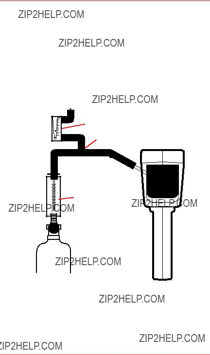
The calibration procedure requires the use of a bypass tee to allow the gas to be drawn into the flow cell without creating variable pressure or dilution problems. Calibration gas cannot be fed into the flow cell under pressure.
When applying calibration gas use the bypass tee as shown in Figure 4 on page 11. The flowrate of calibration gas should be high enough that at least 0.5 SCFH is flowing out of the calibration tee.This can be measured with the supplied flowmeter and insures that air is not being drawn into the unit and diluting the calibration gas.

Note:
The unit may be zeroed without spanning it; however, never span the unit without first zeroing it.
The following procedure will calibrate the
To Enter ZERO / SPAN Mode
1.Push power button to turn unit on. Wait for power up sequence to finish (30 seconds).
2.Push and hold the unnamed button (second from left) first, then Push and hold the Menu button. Hold both buttons until the screen goes blank (2 seconds). Release both buttons and the unit is now in Programming Mode.
3.Push the SENS button and the unit is now in the zero/span mode.
Zero Calibration
4.Be sure the unit is in clean air or apply zero air for two minutes.
5.Push ZERO button.
6.Push SAVE button to save the new zero calibration.
Span Calibration
7.Push SPAN button.
8.Apply span gas for two minutes.
9.Push INC button (increase) or DEC button (decrease) until the display matches the span gas concentration.
10.Push SAVE button to store new span calibration.
To Exit ZERO / SPAN Mode
11.Push DONE button twice slowly to get back into normal operation mode.
3.4Troubleshooting
The detector does not start: Check to see that a fresh battery is installed. Both the primary and standby batteries must be discharged for this problem to occur. Plug the charger into the Honeywell
The detector does not respond to the target gas: Verify the proper flow rate using the supplied flowmeter. Perform calibration. If sensor won???t calibrate, the
Pump alarm: This will occur if the pump motor stops or if an internal pressure sensor detects blockage of the inlet. Check that the internal filter is not clogged or wet and that the inlet tube is clear.
External flowmeter indicates no flow: Verify that pump is running. Check that the manifold screws are tight and the extension wand connection is tight.
Unit does not respond when keys are pressed: Press and hold all four buttons for five seconds. This will reset the Honeywell
High reading won???t clear: When the sensor is exposed to very high gas concentrations, it takes a relatively long time for the sensor to clear. Leave the unit running in a clean environment for a few hours to clear the sensor. If it doesn???t clear after six hours, the sensor may have been damaged. Contact Honeywell Analytics for a replacement
Unit is in alarm with gas reading of 0 ppm: Check the alarm setpoints and alarm functions as described on page 12. Verify that alarm is not programmed as a downscale alarm, and that the setpoint is above zero.
1.0
.8
.6
.4
.2
LPM AIR
Vent through flowmeter
Bypass Tee
Calibration gas flowmeter
TEST UNIT PRIOR TO USE
OUTLET
INLET
CAUTION
DO NOT BLOCK INLET
OR OUTLIET PORTS
Calibration gas bottle
(use only Certified Calibration Gas)
Figure 4. Calibration of the Honeywell

4 Programming and Advanced Features
4.1 Alarm Setpoints, Functions
The Honeywell
To Enter CAUT / WARN / ALRM Mode
1.Push power button to turn unit on. Wait for power up sequence to finish (30 seconds).
2.Push and hold the unnamed button first, then Push and hold the Menu button. Hold both buttons until the screen goes blank (two seconds). Release both buttons and the unit is now in Programming Mode.
3.Push the ALRM button and the unit is now in the CAUT / WARN / ALRM mode.
Warning Setpoint
4.Push WARN button.
5.Push S.P. button (setpoint).
6.Push INC button (increase) or DEC button (decrease) until the display matches the desired warning setpoint. Notice the minus sign above the arrow if the setpoint is below zero.
7.Push SAVE button to store new warning setpoint.
8.Push DONE button to return to Alarms mode.
To Exit CAUT / WARN / ALRM Mode
9. Push DONE button twice slowly to get back into normal operation mode.
The Caution and Alarm setpoints are programmed in the same manner, except for step four above in which you would push either the CAUT or ALRM button. The function of each alarm can be selected to alarm on increasing gas concentration (UP arrow), alarm on decreasing gas concentration (DOWN arrow), or be disabled (off). The following procedure will set the Warning function to alarm on decreasing concentration (Useful for Oxygen Depletion warning).
To Enter CAUT / WARN / ALRM Mode
1.Push power button to turn unit on. Wait for power up sequence to finish (30 seconds).
2.Push and hold the unnamed button first, then Push and hold the Menu button. Hold both buttons until the screen goes blank (two seconds). Release both buttons and the unit is now in Programming Mode.
3.Push the ALRMS button and the unit is now in the CAUT / WARN / ALRM mode.

Warning Function
4.Push WARN button.
5.Push FUNC (function) button.
6.Push SELECT button while viewing the arrow in the lower left hand corner of the screen to toggle through the following three possibilities:
???UP arrow ??? Warn on increasing concentration (gas goes higher than setpoint).
???DOWN arrow ??? Warn on decreasing concentration (gas goes lower than setpoint).
???Blank ??? warning function turned OFF.
7.Push SAVE button when the DOWN arrow is displayed to store new warning function.
8.Push DONE button to return to Alarms mode.
To Exit CAUT / WARN / ALRM Mode
9.Push DONE button two times slowly to get back into normal operation mode.
The Caution and Alarm functions are programmed in the same manner, except for step four above in which you would push either the CAUT or ALRM button.
4.2 Display Variables
The Honeywell
To Enter AVG / BLANK Mode
1.Push power button to turn unit on. Wait for power up sequence to finish (30 seconds).
2.Push and hold the unnamed button first, then Push and hold the Menu button. Hold both buttons until the screen goes blank (two seconds). Release both buttons and the unit is now in Programming Mode.
3.Push the MORE button.
4.Push the DISP (display) button and the unit is now in the AVG / BLANK mode.

AVG Variable
5.Push AVG button.
6.Push INC button (increase) or DEC button (decrease) until the display matches the desired value.
7.Push SAVE button to store new AVG variable.
To Exit AVG / BLANK Mode
8. Push DONE button twice slowly to get back into normal operation mode.
The Blanking variable is programmed in the same manner, except for step 5 above in which you would push the BLANK button.
4.3 Sample Mode
The Sample Mode feature allows the user to take a measurement using a predefined repeatable method to eliminate user ???interpretation??? of a gas concentration that is changing. This is similar to a digital scale, for example, so the exact same reading will be taken regardless of who is taking it.
The measuring sequence used in Sample Mode is as follows:
???Draw a Sample for a user programmed sampling time to allow unit to stabilize to the existing gas concentration.
???Measure the gas concentration and average it for a user programmed measuring time.
???Clear the gas concentration to below a user programmed recovery value before allowing another cycle to start. (Unit should be moved to fresh air during the clear time.)
Taking a sample
To take a sample, locate the detector at the desired sample location, and push the SMPL (sample) button on the normal operation screen. The unit will count down the Sample time, followed by the Measure time, at the end of which the average value will be displayed.
Note the displayed sample value. Pushing the CLEAR button will return the unit to the normal operation screen once the gas concentration is below the predefined recovery value. The unit is now ready to take another sample if desired.
Programming sample mode variables
The sample mode variables are Sample, Measure and Clear as described above. The following procedure will change the Sample variable.
To Enter SAMP / MEAS / CLEAR Mode
1.Push power button to turn unit on. Wait for power up sequence to finish (30 seconds).
2.Push and hold the unnamed button (second from left) first, then Push and hold the Menu button. Hold both buttons until the screen goes blank (two seconds). Release both buttons and the unit is now in Programming Mode.

3.Push the MORE button.
4.Push the SMPL (sample) button and the unit is now in the SAMP / MEAS / CLEAR mode.
SAMP Variable
5.Push SAMP (sample) button.
6.Push INC button (increase) or DEC button (decrease) until the display matches the desired value. The display is in minutes and seconds.
7.Push SAVE button to store new SAMP variable.
To Exit SAMP / MEAS / CLEAR Mode
8. Push DONE button twice slowly to get back into normal operation mode.
The Measure and Clear variables are programmed in the same manner, except for step five above in which you would push the MEAS or CLEAR button.
4.4 Data Logging
The Honeywell
The Honeywell
Prior to your first datalogging session it is recommended that you connect the Honeywell
Data Logging with the Honeywell
To Start the Data Logging Session
1.Push power button to turn unit on. Wait for power up sequence to finish (30 seconds).
2.Push the MENU button.
3.Push the LOG button and the unit is now in the CLEAR / INT / START mode.
4.If the CLEAR button is available, that means there is data currently stored in the unit. If desired, you can erase the data already in the unit by pushing the CLEAR button. (If you don???t push CLEAR, each data logging session can be downloaded as a separate file).

5.Push INT button (interval) to cycle through the choices for how often to log a data point. Stop when the desired interval is displayed. Notice how much time can be covered with the remaining free memory.
6.Push and hold the START button until the screen goes blank (two seconds) to begin a new data logging session. The unit will now display the gas concentration. The Lg symbol in the left side of the display indicates that the unit is logging data. If you watch this symbol carefully, you will see it change to an ???s??? each time a data point is stored.
To Stop the Data Logging Session
7.Push the MENU button.
8.Push the LOG button.
9.Push and hold the STOP button until the screen changes to CLEAR / INT
/START / MODE (two seconds).
10.Push the DONE button to get back into normal operation mode.
Working with the
The
Turn on the Honeywell
The program contains two tabs, one marked ???Download??? and one marked ???Configure???. Review the settings on the ???Configure??? tab, making changes as necessary.
From the ???Download??? tab, review the Link Status block in the lower right hand corner. It should indicate ???Link OK???. Link Trouble can be caused by selection of the wrong Com port in the Configure Tab, improperly connecting the
turning on the Honeywell
When you are ready to transfer data from the Honeywell
These files can now be opened with Excel (use .csv filename), Lotus 123, or other user supplied programs.
4.5 Analog Output
The Honeywell

Each SMARTCELL has a wide range of choices of full scale values.
Note:
The full scale range as programmed below only affects the analog output and the data logging
The display will always cover the entire operating range of the
Changing the full scale range on
To Enter RANGE Mode
1.Push power button to turn unit on. Wait for power up sequence to finish (30 seconds).
2.Push and hold the unnamed button (second from left) first, then Push and hold the MENU button. Hold both buttons until the screen goes blank (two seconds). Release both buttons and the unit is now in Programming Mode.
3.Push the MORE button.
4.Push the DISP (display) button.
5.Push the MORE button and the unit is now in the RANGE mode.
Adjusting the RANGE
6.Push RANGE button.
7.Push INC button (increase) or DEC button (decrease) until the display matches the desired full scale range.
8.Push SAVE button to store new full scale range.
To Exit RANGE Mode
9. Push DONE button twice slowly to get back into normal operation mode.
Appendix A
Available

22
Manual Installation and Instruction
B Appendix
Gases) (Interference Table

Notes:
1.None means there is no interference.
2.A number indicates that when exposed to the interference gas, the sensor will react the specified amount for a given concentration. For example,
on the first line of the table above, if the NO2 sensor is exposed to 1 ppm Bromine (Br2), the sensor will read 0.5 ppm.This interference is in addition to the target gas present.
For example, if an NH3 sensor is exposed to 1 ppm NH3 and 1 ppm Br2 at the same time, the reading will be 0.9 ppm

Limited Warranty
1.Limited Warranty
Honeywell Analytics Inc.. (???HA???) warrants to the original purchaser and/or ultimate customer (???Purchaser???) of HA???s Products (???Product???) that if any part thereof proves to be defective in material os workmanship within eighteen (18) months of the date of shipment by HA or twelve (12) months from the date of first use by the Purchaser, whichever comes first, such defective part will be repaired or replaced, free of charge, at HA???s discretion. For service repairs, contact HA at
1 800 321 6320
to obtain a service authorization number, then ship prepaid to
Honeywell Analytics Inc.
405 Barclay Blvd
Lincolnshire, IL 60069
Attn: Service Dept
The Product must be in a package equal to or in the original container. The Product will be returned freight prepaid and repaired or replaced if it is determined by HA that the part failed due to defective materials or workmanship. The repair or replacement of any such defective part shall be HA???s sole and exclusive responsibility and liability under this limited warranty.
2.Exclusions
A.If gas sensors are part of the Product, the gas sensor is covered by a twelve (12) month limited warranty of the manufacturer.
B.If gas sensors are covered by this limited warranty, the gas sensor is subject to inspection by HA for extended exposure to excessive gas concentrations if a claim by the Purchaser is made under this limited warranty.
C.This limited warranty does not cover consumable items such as batteries, or items subject to wear or periodic adjustment, including lamps, fuses, valves, vanes, sensor elements, cartridges, or filter elements.
3.Warranty Limitation and Exclusion
Honeywell Analytics will have no further obligation under this limited warranty. All warranty obligations of Honeywell Analytics are extinguishable if the Product has been subject to abuse, misuse, negligence, or accident or if the Purchaser fails to perform any of the duties set forth in this limited warranty or if the Product has not been operated in accordance with the instructions, or if the Product serial number has been removed or altered.
4.Disclaimer of Unstated Warranties
THE WARRANTY PRINTED ABOVE IS
THE ONLY WARRANTY APPLICABLE
TO THIS PURCHASE. ALL OTHER
WARRANTIES, EXPRESS OR IMPLIED,
INCLUDING, BUT NOT LIMITED TO
THE IMPLIED WARRANTIES OF
MERCHANTABILITY OR FITNESS
FOR A PARTICULAR PURPOSE ARE
HEREBY DISCLAIMED.
5.Limitation of Liability
IT IS UNDERSTOOD AND AGREED
THAT HONEYWELL ANALYTICS???
LIABILITY, WHETHER IN CONTRACT,
IN TORT, UNDER ANY WARRANTY, IN
NEGLIGENCE OR OTHERWISE SHALL
NOT EXCEED THE AMOUNT OF THE
PURCHASE PRICE PAID BY THE
PURCHASER FOR THE PRODUCT
AND UNDER NO CIRCUMSTANCES
SHALL HONEYWELL ANALYTICS BE
LIABLE FOR SPECIAL, INDIRECT,
OR CONSEQUENTIAL DAMAGES.
THE PRICE STATED FOR THE
PRODUCT IS A CONSIDERATION
LIMITING HONEYWELL ANALYTICS???
LIABILITY. NO ACTION, REGARDLESS
OF FORM, ARISING OUT OF THE
TRANSACTIONS UNDER THIS
WARRANTY MAY BE BROUGHT BY
THE PURCHASER MORE THAN ONE
YEAR AFTER THE CAUSE OF ACTION
HAS OCCURRED.


Find out more
www.honeywellanalytics.com
Contact Honeywell Analytics:
Americas
Honeywell Analytics 405 Barclay Boulevard Lincolnshire, IL 60069
USA
Tel: +1 847 955 8200
Toll free: +1 800 538 0363
Fax: +1 847 955 8208 detectgas@honeywell.com
Technical Services
ha.global.service@honeywell.com
www.honeywell.com
Please Note:
While every effort has been made to ensure accuracy in this publication, no responsibility can be accepted for errors or omissions.
Data may change, as well as legislation, and you are strongly advised to obtain copies of the most recently issued regulations, standards and guidelines.
This publication is not intended to form the basis of a contract.
11385 Rev J
July 2009
?? 2009 Honeywell Analytics