ML6874
Valve Actuator
PRODUCT DATA
FEATURES
??? Allows the use of one common transformer power supply for multiple actuators and controllers
??? Self-contained, motorized valve linkage
??? Linkage self-adjusts to valve stroke of up to 19mm (3/4")
??? Multipose mounting
??? Strong valve seat closing force 710 Newton (160 lbs.)
??? Compact size for easy installation in confined area
??? Field-configurable DIP switches for Direct/Reverse action
??? One device for either Vac or Vdc power supply application
??? Electronic current sensing provides internal protection and positive full closing force
??? Field-addable auxiliary switches available
GENERAL
The ML6874 is a self-contained, self-adjusting, linear motorized linkage that mounts directly onto V5011 two-way or V5013 three-way valves and provides up to 19 mm (3/4") of linear travel (stem lift). For use with low voltage 3-wire SPDT
Series 20 (on-off) or Series 60 (floating) controllers.
ML6874
SPECIFICATIONS ??? ORDERING INFORMATION
Specifications
IMPORTANT:
The specifications given in this publication do not include normal manufacturing tolerances. Therefore, an individual unit may not exactly match the listed specifications. Also, this product is tested and calibrated under closely controlled conditions and some minor differences in performance can be expected if those conditions are changed.
Ambient Rating:
Operating Temperature: 0??C to 55??C (32??F to 131??F) Shipping Temperature:
-40??C to +65??C (-40??F to 150??F) Relative Humidity:
15% to 95% at 40??C (104??F)
Acoustic Noise:
55 dBA max. Sound Pressure Level at 1 m (39") distance.
Electrical Ratings:
Power supply/consumption: 24V (Nominal), 50/60Hz or 24 to 28 Vdc
6VA(Running), 12VA(Valve seating)
Shipping Weight:
Approx. 1 kg (2.2 lbs)
Accessories/Parts:
272630A--Auxiliary switch assembly (1-SPDT)
272630B--Auxiliary switch assembly (2-SPDT)
272775-- Replacement motor brush kit
40003793-003--Mounting hardware bag assembly
Mechanical Ratings:
Stroke--19mm (3/4") or less
Stroke timing-- Approx. 63 seconds for 3/4" stroke Closing Force-- 710N (160 lbs.) Nominal*
*Rating applies to both directions.
Performance Specifications:
Life Expectancy-- (at rated load and power conditions) 50,000 full stroke cycles plus 1,000,000 repositions at 10% stem travel or 10 years, whichever occurs first.
Note: rapid cycling/repositioning will result in reduced service life of the actuator.
Ordering Information
When purchasing replacement and modernization products from your wholesaler or distributor, refer to the price sheets for complete ordering number, or specify-??
1.Model number.
2.Valve body type and model number.
3.Accessories, if desired.
If you have additional questions, need further information, or would like to comment on our products or services, please write or phone:
1.Your local Honeywell Home and Building Control Sales office ( check white pages of your phone directory ).
2.Home and Building Control Customer Relations
Honeywell Limited/Honeywell Limit??e
35 Dynamic Drive
Scarborough, Ontario
M1V 4Z9
In U.S.A. -- Honeywell, 1885 Douglas Drive North, Minneapolis, Minnesota 55422-4386
International Sales Offices in all principal cities of the world. Manufacturing in Australia, Canada, Finland, France, Germany, Japan, Mexico, Netherlands, Spain, United Kingdom, U.S.A.
ML6874
SPECIFICATIONS ???INSTALLATION
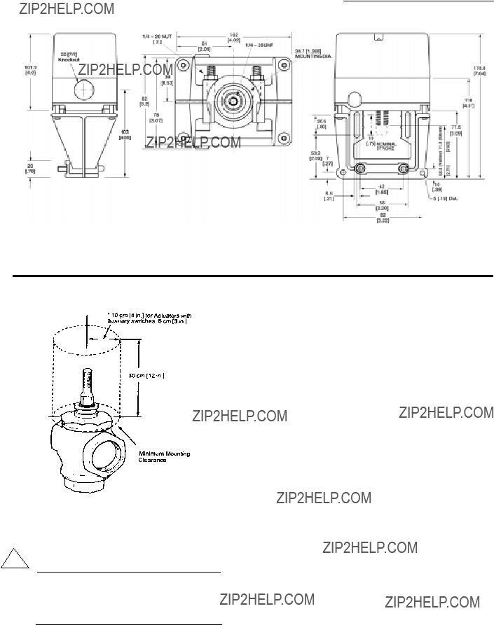
FIG. 1 -- DIMENSIONS OF ML6874 VALVE ACTUATOR IN MM (INCHES).
Installation
Mounting:
1. Ensure that the valve body is installed correctly, that is, the arrow points in the direction of the flow.
2. Although the actuator can be mounted in any position, it is preferable that the ML6874 is mounted above the valve body. This will minimize the risk of damage to the ML6874 in the event of condensation or a valve gland leak.
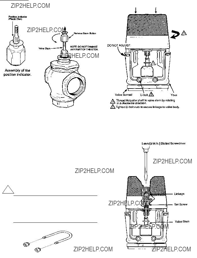
3. Remove the stem button (Fig. 3) from the valve stem. Save the set screw inside the stem button for later installation. The button itself is not needed.
4. Slide the position indicator (plastic disk or rubber O-ring) over the valve stem. (See inset, Fig. 3) Indicator will self?? align to the marking on the yoke after one complete operating cycle.
FIG.2 -- MINIMUM MOUNTING CLEARANCE.
!CAUTION
1.Installer must be a trained service technician.
2.DO NOT electrically operate the ML6874 before assembly to the valve because damage not apparent to the installer may occur.
Assembly of ML6874 to the valve:
1.The drive shaft of the ML6874 has a threaded hole to link with the valve stem. Slide the yoke over the valve bonnet (Fig. 4)
2.Thread the ML6874 drive shaft onto the valve stem all the way, until it is completely attached (with no threads showing), by turning the valve actuator in a clockwise direction, as viewed from above (depending on the valve models, use a pin or wrench to keep valve stem from turning). Note that the valve actuator is shipped with drive shaft in the mid-position.
3.Care should be exercised when using tools on the valve stem during tightening. (Fig.4) DO NOT damage the threads or other parts of the stem.
4.Orient the conduit hole to the most desirable direction, then tighten the LOCKNUTS on the U-bolt.
ML6874
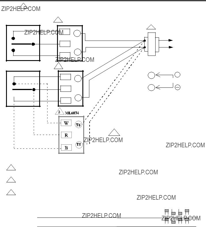
WIRING
3
SPDT
Controller
 B
B
! Caution:
In multiple actuators connection, power supply to all actuators must be connected in a TRUE parallel fashion to reduce excessive voltage drop. DO NOT "daisy chain" i.e. connected to one actutator then branched to another.
Allow 0.5 amps maximum for each device. Actuators and controller can share same transformer providing the
1VA rating of the transformer is not exceeded and proper phasing is observed.
Use configuration DIP switches to select device functions: Direct acting function (actuator stem moves upwards
2with R & B closed ) or Reverse acting function ( actuator stem moves downwards with R & B closed ). DO NOT reverse wiring.
3 SPDT controller can be a low voltage Series 20 "on-off " or Series 60 "floating" (center-off) type.
NOTE:
Turn power off before setting the DIP switches.
Fig. 7 Wiring for SPDT controller to ML6874 actuators