Solid State Economizer System
(CONSISTING OF: C7046C DISCHARGE AIR SENSOR OR C7150B MIXED AIR SENSOR, C7400A
SOLID STATE ENTHALPY SENSOR OR C7650A SOLID STATE TEMPERATURE SENSOR, M7415
OR M8405 DAMPER ACTUATORS OR MODULATING DIRECT COUPLED ACTUATORS (MS7505), T6031H THERMOSTAT AND W7459 OR W7212 SOLID STATE ECONOMIZER LOGIC MODULE)
PRODUCT DATA
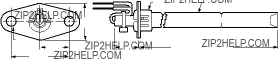
C7046C
M7415/M8405
C7150B
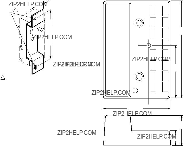
W7459A,C
W7212
C7400A/C7650A T6031H
APPLICATION
The Solid State Economizer System provides an economical method of providing cooling air by incorporating outdoor air in the first stage of cooling in heating, ventilating and air conditioning (HVAC) systems. The Solid State Economizer System consists of the C7046C Discharge Air Sensor or C7150B Mixed Air Sensor, C7400A Solid State Enthalpy Sensor or C7650A Solid State Temperature Sensor, M7415 or M8405 Damper Actuators or Modulating Direct Coupled Actuators (MS7505), T6031H Thermostat and W7212 or W7459A,C Solid State Economizer Logic Module.
FEATURES
C7046C Discharge Air Sensors have probe lengths of 8 in. (203 mm) and nominal sensor resistance of 3000 ohms at 77??F (25??C).
???No setting or calibration required.
???Solid state components not affected by dust or dirt.
???Fast reacting.
???Rugged aluminum insertion probe.
C7150B Mixed Air Sensor is used with the W7212/W7459 Economizer Module to sense mixed or discharged air in roof- top packaged air conditioning equipment.
??? No setting or calibration required.
C7400A Solid State Enthalpy Sensor and C7650A Solid State Temperature Sensors are used with the W7212/W7459 Solid State Economizer Logic Module to sense outdoor and return air enthalpy or temperature.
???C7400A senses and combines temperature and humidity (enthalpy) of outdoor air (heat index).
???C7650A senses temperature only.
???When enthalpy/temperature of outdoor air increases, the outdoor air damper closes to a preset minimum position.
???When enthalpy/temperature of outdoor air is low, the outdoor air damper opens to reduce the building cooling load.
???Additional economizer savings are achieved when two C7400A Solid State Enthalpy Sensors are connected to one Logic Module for differential enthalpy changeover control.
Contents

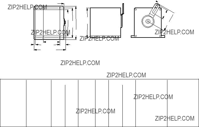
 4-1/2
4-1/2
 1/4 (6)
 7/8 (22)


 CAUTION
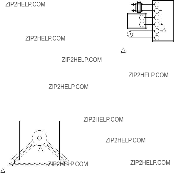
 CAUTION
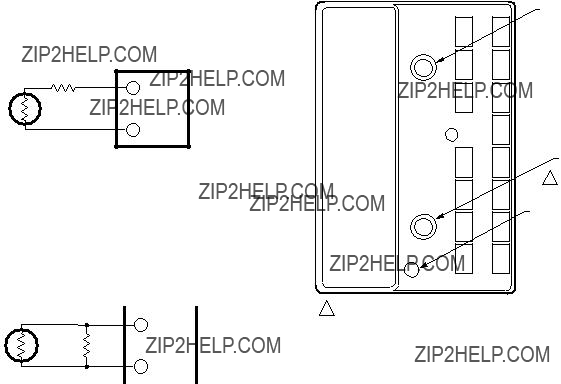
 MOTOR MOUNTING SURFACE
 SYSTEM DUCT OR PLENUM
 FLANGE
 CAUTION
 CAUTION
 CAUTION
 5/8 INCH SCREW INCLUDED WITH LOGIC MODULE.
 CAUTION


 CAUTION


 CAUTION
 DCV
DCV