203365A 120 Vac to 220/240 Vac Conversion Kit For Electronic Air Cleaners

Application

The 203365A Conversion Kit changes the 120 Vac, 60 Hz to 220/240 Vac, 50/60 Hz. The kit includes a trans- former and two screws. The line cord on the air cleaner must be changed to conduit to complete the conversion.

NOTE: The air cleaner can be completely isolated from the electrical circuit of the HVAC system unless re- quired by local code to use same circuit. Any convenient house circuit can power the air cleaner, regardless of electrical rating of HVAC system.

Installation

WHEN INSTALLING THIS PRODUCT???

1. Read these instructions carefully. Failure to follow them could damage the product or cause a hazardous condi- tion.

2.Check the ratings given in the instructions and on the product to make sure the product is suitable for your application.

3.Installer must be a trained, experienced service technician.

4.After installation is complete, check out product operation as provided in these instructions.

MOUNT TRANSFORMER

1.Open access door.

2.Remove and retain the two screws from the front of the power box.

3.Lift and remove the power box.

4.Remove and retain the two screws from the sides of the power box. See Fig. 1.

5.Remove the power box cover.

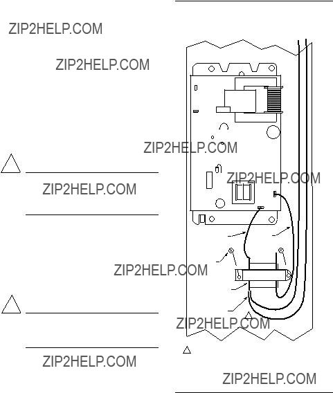
6.Place the transformer on the mounting holes. See Fig. 2.

Fig. 1???Remove power box.

3

2

1

4

M6168

J. H. ??? Rev. 8-93 ??? ??Honeywell Inc. 1993 ??? Form Number 69-0769???1

NOTE: Be sure the transformer terminals are located on the side away from the power supply. See Fig. 2.

7. Use the two provided screws to secure the trans- former to the power box.

WIRE TRANSFORMER TO POWER SUPPLY

(See Fig. 2)

1.Remove black wire from power supply P1 terminal and place it on one of the transformer terminals.

2.Connect the transformer black lead to the power supply P1 terminal.

3.Remove brown wire from power supply P2 terminal and place it on the empty transformer terminal.

4.Connect the transformer brown lead to the power supply P2 terminal.

See Fig. 3 for internal schematic for the electronic air cleaner with conversion kit.

CHANGE PLUG TO CONDUIT

! CAUTION

ELECTRIC SHOCK HAZARD.

CAN CAUSE ELECTRICAL SHOCK OR

EQUIPMENT DAMAGE.

Disconnect power before installing replacement power supply board.

1.In the power box, remove and retain two wire nuts that connect the line cord leads to the power box wiring.

2.Remove the power green lead from the green ground- ing screw on the wiring compartment barrier.

3.Remove the power cord and the strain relief.

4.Put the provided plug in the hole left by the power

cord.

COMPLETE WIRING

! CAUTION

ELECTRIC SHOCK HAZARD.

CAN CAUSE ELECTRICAL SHOCK OR

EQUIPMENT DAMAGE.

Disconnect power before wiring.

1.Attach conduit through a power box side knock-out.

2.Wire the air cleaner directly to the line voltage using wire nuts. See Fig. 3. Secure ground connection to the green ground screw on the wiring compartment barrier.

3.Replace power supply box, cover and access door.

Fig. 2???Mount and wire transformer.

P3

P4

J2

2

4

3

1

R43

P2

MOUNTING

SCREWS (2)

BLACK

TERMINALS

1BROWN

1BROWN AND BLACK WIRES OFF OF P1 AND P2 TERMINALS

CAN GO ON EITHER TRANSFORMER TERMINAL.

M5767

2

Fig. 3???Internal schematic for electronic air cleaner with 203365A Conversion Kit.

5ONE-CELL UNIT SIMILAR, BUT WITH JUST ONE CELL.

6POWER SUPPLY. PROVIDE DISCONNECT MEANS AND OVERLOAD PROTECTION AS REQUIRED.

M5765A

Checkout

! WARNING

ELECTRIC SHOCK HAZARD.

CAN CAUSE PERSONAL INJURY OR

EQUIPMENT DAMAGE.

The following procedures expose hazardous live parts. Disconnect from power supply between checks and proceed carefully. These instructions are for use by only qualified personnel.

With all components in place, connect power to the air cleaner. Turn on the air cleaner switch to energize the system blower. Check the following points of operation:

1.The neon light next to the on-off switch is on. If a W8600E is part of the installation, check the wall panel and make sure the ON LED is lit. The W8600E CHECK LED will come on if there is a problem with the high voltage power supply.

2.Turn off the system blower. The neon light should go off after a few seconds. The neon light indicates that the air cleaner is energized and the high voltage power supply is working properly.

3.Turn on the system blower. With the air cleaner energized, push the test button. A snapping sound indi- cates that the collector voltage is present on the cell. The W8600E CHECK LED will come on when the test button is held down.

4.With a multispeed blower, repeat steps 1 through 3 for each fan speed.

5.If operation is not as described, refer to the Electrical Troubleshooting section.

Electrical Troubleshooting

! WARNING

ELECTRIC SHOCK HAZARD.

CAN CAUSE PERSONAL INJURY OR

EQUIPMENT DAMAGE.

The following procedures expose hazardous live parts. Disconnect from power supply between checks and proceed carefully. These instructions are for use by only qualified personnel.

TOOLS AND EQUIPMENT

Troubleshooting the electronic air cleaner requires:

???Needle nose pliers for stringing ionizer wires and inserting edge connectors.

???Test meter.

NEON LIGHT (On Power Box)

The neon light is powered through the power supply and is on when the power supply output voltage is normal.

TEST BUTTON

When pushed, the test button shorts from collector voltage to ground. The resulting arcing sound indicates that high voltage is being supplied to the collector. The solid state power supply controls current flow to the collector. On air cleaners with a W8600E, the CHECK LED will come on when the test button is held down.

CHECK LED (Air Cleaners with W8600E)

The CHECK LED is on the W8600E. It lights to indicate the following problems: excessive dirt loading (beyond that required to activate the WASH LED), partial shorting of the collector, continuous ionizer or collector arcing, power supply failure, excessive ionizer current, or any condition causing a major reduction in high voltage.

POWER BOX

! WARNING

ELECTRIC SHOCK HAZARD.

CAN CAUSE PERSONAL INJURY.

Always turn off power and remove access door before removing power supply or its cover.

The solid-state power supply within the power supply box can be replaced. When troubleshooting indicates a power supply or solid-state performance indicator prob- lem, replace the entire power box or replace the power supply within the box. See Installation Instructions, form 69-0776. See Fig. 1 for power box removal.

TROUBLESHOOTING PROCEDURE

The electronic air cleaner troubleshooting chart shows how to quickly isolate a problem in the air cleaner. See Fig. 4. Although a meter is needed for some steps, the primary diagnostic tools are the neon light and the test button.

4

Fig. 4???Troubleshooting air cleaners with solid-state performance indicator.

START

MAKE SURE ELECTRONIC

CELL(S) ARE CLEAN, DRY

AND PROPERLY INSTALLED.

MAKE SURE PREFILTER(S)

ARE IN CABINET SLOT

FARTHEST FROM FURNACE.

TURN ON ELECTRONIC AIR

CLEANER AND SYSTEM FAN.

TO USE THIS CHART:

1.FOLLOW THE STEPS IN ORDER, DO NOT SKIP AROUND.

2.EACH TIME YOU ISOLATE AND FIX A PROBLEM,

GO BACK TO START.

3.REPEAT ALL THE STEPS UNTIL THE AIR CLEANER

CHECKS OUT OK.

CORRECT

WIRING.

WIRING

NOT OK

CHECK WIRING BETWEEN W8600E AND AIR CLEANER. USE MAX. NO. 18 4-WIRE

THERMOSTAT CABLE CONNECTED 1(G) TO 1(G), 2(Y) TO 2(Y), 3(R) TO 3(R), AND 4(B) TO 4(B).

WIRING OK

REPLACE

W8600E. 3

OFF

CHECK NEON LIGHT.

ON

OFF

DEPRESS AND HOLD DOWN

TEST BUTTON. CHECK

LED IN W8600E

2

SHOULD COME ON

ON

TURN OFF AIR CLEANER

AND REMOVE CELL(S)

ONLY (NOT PREFILTERS).

CLOSE ACCESS DOOR

AND TURN ON AIR CLEANER.

ON

TURN OFF AIR CLEANER

AND REMOVE CELL(S)

ONLY (NOT PREFILTERS).

CLOSE ACCESS DOOR

AND TURN ON

AIR CLEANER.

OFF

CHECK NEON LIGHT.

ON

INSPECT CELL(S) FOR:

???BENT COLLECTOR

PLATES

???BROKEN IONIZER

WIRES

???DIRT ON INSULATORS

???DAMAGED IONIZER

OR COLLECTOR

CONTACT TABS

YES

REPAIR OR

REPLACE

CELL(S).NO

WITH OHMMETER,

REPLACE LIGHT/

SWITCH ASSEMBLY.

WARNING

THIS STEP EXPOSES

DANGEROUS HIGH

VOLTAGE. ONLY A

QUALIFIED SERVICE

TECHNICIAN SHOULD

ATTEMPT THIS STEP.

CHECK FOR CORRECT

INPUT VOLTAGE ACROSS

P1 AND P2 TERMINALS

ON POWER SUPPLY.

NOYES

FIX

WIRING.

TURN OFF AIR CLEANER,

REPLACE CELLS(S) AND DISCONNECT 4 W8600E

LEADS AT AIR CLEANER.

REPLACE ACCESS DOOR.

TURN ON AIR CLEANER.

PUSH TEST BUTTON

AND LISTEN FOR

ELECTRONIC AIR CLEANER AND W8600E ARE OK.

CHECK FOR SHORT

BETWEEN:

SNAPPING SOUND.

NO

REPLACE

POWER

YES

BOX OR 1

POWER SUPPLY.

AIR CLEANER OK.

TURN OFF AIR CLEANER AND RECONNECT W8600E LEADS 1(G) TO 1(G), 2(Y) TO 2(Y), 3(R) TO 3(R), AND 4(B) TO 4(B).

M5609

Printed in U.S.A.