OPERATOR'S MANUAL

Vac Attack II Blower / Vacuum

UT08932, UT08934 and UT08934B

Your new blower has been engineered and manufactured to Homelite???s high standard for dependability, ease of operation, and operator safety. Properly cared for, it will give you years of rugged, trouble-free performance.

WARNING: To reduce the risk of injury, the user must read and understand the operator???s manual before using this product.

Thank you for buying a Homelite blower.

SAVE THIS MANUAL FOR FUTURE REFERENCE

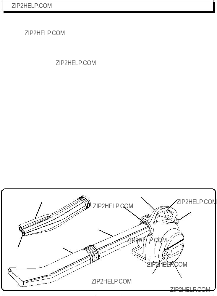
With the Vac Attack II Blower, clearing leaves, pine needles and other debris from your lawn, driveway, or deck will be a breeze. Safety, performance, and dependability have been given top priority in the design of this blower making it easy to maintain and operate.

Page 2

GENERAL SAFETY RULES

WARNING:

Read and understand all instructions. Failure to follow all instructions listed below may result in electric shock, fire and/or serious personal injury.

???Do not allow children or untrained individuals to use this unit.

???Never start or run the engine inside a closed area; breathing exhaust fumes can kill.

???Wear eye protection which is marked to comply with ANSI Z87.1 as well as hearing protection when operating this equipment.

???Keep all bystanders, children, and pets at least 50 feet (15 m) away.

???Wear heavy long pants, boots, and gloves. Do not wear loose fitting clothing, short pants, jewelry of any kind, or go barefoot.

???To reduce the risk of injury associated with objects being drawn into rotating parts, do not wear loose clothing, scarves, neck chains, and the like. Secure long hair so it is above shoulder level to prevent entanglement in any rotating parts.

???Do not operate this unit when you are tired, ill, or under the influence of alcohol, drugs, or medication.

???Do not operate in poor lighting.

???Keep all parts of your body away from any moving parts and all hot surfaces of the unit.

???Wear a face filter mask in dusty conditions to reduce the risk of injury associated with the inhalation of dust.

???Check the work area before each use. Remove all objects such as rocks, broken glass, nails, wire, or string which can be thrown or become entangled in the machine.

???Keep firm footing and balance. Do not overreach. Over- reaching can result in loss of balance or exposure to hot surfaces.

???Never operate the unit without a spark arrestor screen; this screen is located inside the muffler.

???Product users on United States Forest Service land, and in some states, must comply with fire prevention regula- tions.This product is equipped with a spark arrestor; how- ever, other user requirements may apply. Check with the federal, state, or local authorities in your area.

???Before storing, allow the engine to cool.

???Empty fuel tank and restrain the unit from moving before transporting in a vehicle.

???To reduce the risk of fire and burn injury, handle fuel with care. It is highly flammable.

???Do not smoke while handling fuel.

???Mix and store fuel in a container approved for gasoline.

???Mix fuel outdoors where there are no sparks or flames.

???Select bare ground, stop engine, and allow to cool before refueling.

???Loosen fuel cap slowly to release pressure and to keep fuel from escaping around the cap.

???Tighten the fuel cap securely after refueling.

???Wipe spilled fuel from the unit. Move 30 feet (9 m) away from refueling site before starting engine.

???Never attempt to burn off spilled fuel under any circum- stances.

???Use only Homelite replacement parts and accessories. Failure to do so may cause poor performance, possible injury.

???Maintain the unit per maintenance instructions in this Operator's Manual.

???Inspect the unit before each use for loose fasteners, fuel leaks, etc. Replace damaged parts.

Page 3

SPECIFIC SAFETY RULES

???Do not operate vacuum without vacuum bag installed; flying debris could cause serious injury. Always close vacuum bag completely before operating.

???Always hold the blower in your right hand, refer to the ???Op- eration Instructions,??? later in this manual for additional in- formation.

???To reduce the risk of hearing loss associated with sound level(s), hearing protection is required.

???Rotating impeller blades can cause severe injury. Stop the engine before opening the vacuum door or installing / chang- ing tubes. Do not put hands or any other object into the vacuum tubes while they are installed on the unit.

???To reduce the risk of injury associated with contacting ro- tating parts, stop the engine before installing or removing attachments. Do not operate without guard(s) in place. Al-

ways disconnect the spark plug before performing mainte- nance or accessing any movable parts.

???Do not point the blower nozzle in the direction of people or pets.

???Never run the unit without the proper equipment attached. When used as a blower, always install the blower tubes. When used as a vacuum, always install the vacuum tubes and vacuum bag. Make sure the vacuum bag is completely zipped when the unit is running to avoid flying debris.

???Avoid situations that could catch the vacuum bag on fire. Do not operate near an open flame. Do not vacuum warm ash from fireplaces, barbeque pits, brush piles, etc. Do not vacuum discarded cigars or cigarettes unless the cinders are completely cool.

Page 4

SYMBOLS

Some of the following symbols may be used on this tool. Please study them and learn their meaning for safe operation of this product.

Page 5

SYMBOLS

The following signal words and meanings are intended to explain the levels of risk associated with this product.

DANGER: Indicates an imminently hazardous situation which, if not avoided, will result in death or serious injury.

WARNING: Indicates a potentially hazardous situation which, if not avoided, could result in death or serious injury.

CAUTION: Indicates a potentially hazardous situation which, if not avoided, may result in minor or moderate injury.

CAUTION: (Without Safety Alert Symbol) Indicates a situation that may result in property damage.

SERVICE

Servicing requires extreme care and knowledge and should be performed only by a qualified service technician. For service we suggest you return the product to your nearest

AUTHORIZED SERVICE DEALER for repair.When servic- ing, use only identical replacement parts.

WARNING:

Observe all normal safety precautions related to avoid electrical shock.

WARNING:

To avoid serious personal injury, do not attempt to operate this product until you read thoroughly and understand completely the operator's manual. Save this operator's manual and review frequently for continuing safe operation and instructing others who may use this product.

WARNING:

The operation of any products can result in foreign objects being thrown into your eyes, which can result in severe eye damage. Before beginning operation, always wear safety goggles or safety glasses with side shields and a full face shield when needed.We recommend Wide Vision Safety Mask for use over eyeglasses or standard safety glasses with side shields. Always wear eye protection which is marked to comply with ANSI Z87.1.

SAVE THESE INSTRUCTIONS

Page 6

Before using this blower, familiarize yourself with all operat- ing features and safety requirements. However, do not let familiarity with the blower make you careless.

This new blower is equipped with the following features. See Figures 1a and 1b.

MOTOR

The blower has a powerful 30cc engine with sufficient power to handle tough blowing and vacuuming jobs.

THROTTLE TRIGGER

The blower can be operated at any speed between idle and full throttle.

CRUISE CONTROL / THROTTLE LOCK

The Cruise control (throttle lock) feature allows the user to operate the blower without holding the throttle trigger.To stop the engine, simply push the Cruise control knob after the engine has returned to idle speed.

BLOWER TUBE AND NOZZLE

WIDE SWEEPER NOZZLE

The wide sweeper nozzle allows for more area to be covered during blower operation.

HIGH VELOCITY NOZZLE

The high velocity nozzle is great for wet sticky leaves. It allows you to scrape wet leaves or debris while operating the blower.

VACUUM

The blower will covert to a powerful vacuum/mulcher using no tools.

VACUUM BAG

The vacuum bag attaches to the blower easily using the vacuum bag adaptor.

VACUUM TUBES

The vacuum tubes can be installed on the blower without using any tools.

DOOR KNOB

Page 7

FEATURES

VACUUM BAG

ADAPTOR

VACUUM BAG

STARTER GRIP

UPPER VACUUM

TUBE

LOWER VACUUM

TUBE

PRIMER BULB

CHOKE LEVER

INSTRUCTIONS

When unpacking the blower:

???Carefully remove the blower and accessories from the box.

???Make sure that all items listed in the packing list are in- cluded.

???Inspect the blower carefully to make sure no breakage or damage occurred during shipping.

???Do not discard the packing material until you have care- fully inspected and satisfactorily operated the blower.

???If any parts are damaged or missing, please call 1-800-242-4672 for assistance.

LOWER HANDLE

PACKING LIST

Blower

Upper Blower Tube

Wide Sweeper Nozzle

High Velocity Nozzle

Upper and Lower Vacuum Tubes

Vacuum Bag

Vacuum Bag Adaptor

Tube Clamp

2-Cycle Engine Oil

Operator's Manual

Fig. 1b

WARNING:

If any parts are missing do not operate the blower until the missing parts are replaced. Failure to do so could result in possible serious personal injury.

NOTE: Read and remove all hang tags and store with your operator's manual.

Page 8

ASSEMBLY

WARNING:

Stop the engine and disconnect the spark plug wire before installing parts, making adjustments, cleaning, or when not in use. Failure to do so could result in possible serious personal injury.

ASSEMBLING THE BLOWER TUBES

See Figure 2.

1.Screw the nozzle onto the upper blower tube and tighten securely. Check tightness after initial run and retighten if needed.

2.Place clamp around the neck of the blower housing outlet. Do not tighten the wing nut yet.

3.Align the locking tab on upper blower tube with the slot in the blower housing outlet; push the tube into the housing. Twist to lock into place.

4.Rotate the tube so the nozzle is pointing upward as shown. Tighten the wing nut securely.

5.To remove the tubes, loosen the wing nut on the clamp. Rotate the tubes to unlock them remove from the blower housing outlet.

INSTALLING THE VACUUM BAG

See Figures 3 and 4.

1.Remove the nozzle and upper blower tube from the blower.

2.Unzip the vacuum bag and place the adaptor inside as shown.

3.Align the locking tab on the bag adapter with the slot in the blower housing outlet; push the bag adaptor into the housing. Twist to lock into place.

4.Tighten the wing nut securely.

5.Rotate the vacuum bag until the shoulder strap is upright.

6.Make sure the vacuum bag is zipped and closed before starting the unit.

Fig. 2

ADAPTOR

VACUUM BAG

Fig. 3

Fig. 4

Page 9

ASSEMBLY

WARNING:

Stop the engine and disconnect the spark plug wire before installing parts, making adjustments, cleaning, or when not in use. Failure to do so could result in possible serious personal injury.

INSTALLING THE VACUUM TUBES

See Figures 5 and 6.

To install the vacuum tubes:

1.Screw the upper and lower vacuum tubes together and tighten securely.

2.Loosen the door knob on the inlet cover door and open. Place the notch in the support arm of the upper vacuum tube under the hinge of the inlet cover door.

3.Push the upper vacuum tube into the blower housing.

4.Align the upper vacuum tube knob with the hole in the housing and tighten securely.

To remove the vacuum tubes:

1.Loosen the upper vacuum tube knob.

2.Remove the vacuum tubes from the blower housing.

3.Close the inlet cover door and tighten the door knob securely.

INLET COVER

DOOR

DOOR KNOB

Fig. 5

HINGE

UPPER

NOTCH IN

SUPPORT ARM

VACUUM

TUBE KNOB

Fig. 6

Page 10

OPERATION

WARNING:

Gasoline is extremely flammable and explosive. A fire or explosion from gasoline will burn you and others.

MIXING THE FUEL

This product is powered by a 2-cycle engine and requires pre-mixing gasoline and 2-cycle oil. The mixture should be at a 50:1 ratio, using Premium Exact Mix??? 2-cycle engine oil. If Premium Exact Mix??? 2-cycle engine oil is not available, use a high quality 2-cycle engine oil, mixed at a 50:1 ratio. See chart later in this section.

To mix the fuel:

1.Use a clean container that is approved for use with gasoline.

2.Mix the Premium Exact Mix??? 2-cycle engine oil with unleaded gasoline in the container, according to the instructions on the oil package.

IMPORTANT:

This engine is certified to operate on unleaded gasoline intended for automotive use with an octane rating of 87 ([R + M] / 2) or higher. Do not use automotive oil or 2-cycle outboard oil.

NOTE:

Premium Exact Mix??? fuel mixture will stay fresh up to 30 days. DO NOT mix quantities larger than usable in a 30 day period.

PREMIUM EXACT MIX??? (50:1)

FILLING THE TANK

WARNING:

Always stop the engine before filling the fuel tank. Never add fuel to a machine with a running or hot engine. Move at least 30 ft. (9 m) from the refueling area before starting engine. Do not smoke while filling the tank.

1.Clean the surface around the fuel cap to prevent con- tamination.

2.Loosen the fuel cap slowly, by turning it counterclock- wise.

3.Pour the fuel mixture carefully into the tank.

4.Clean and inspect the fuel cap gasket before replacing the fuel cap.

5.Replace the fuel cap and tighten it by turning it clock- wise.

6.Wipe spilled fuel from the product.

7.Move at least 30 ft. (9 m) away from refueling area before starting the product.

NOTE: It is normal for smoke to be emitted from a new engine during first use.

WARNING:

Check for fuel leaks. If you find any leaks, correct the problem before using the product.

WARNING:

A leaking fuel cap is a fire hazard and must be replaced immediately.

Page 11

OPERATION

STARTING AND STOPPING

See Figure 7.

Starting the product differs depending on whether the engine is cold or warm. Refer to the label on the air filter base for choke positions A, B, and C.

TO START A COLD ENGINE:

1.Place the blower on a flat, bare surface.

2.Push the primer bulb, slowly, 5 times.

3.Move the choke lever to the full choke position marked A.

4.Squeeze the throttle trigger to full throttle position.

5.Pull the starter rope until the engine tries to run. Do not pull the starter rope more than 6 pulls.

6.Move the choke lever to the half choke position marked

B.

7.Squeeze the trigger to full throttle position and pull the starter rope until the engine runs.

8.Run the engine 30 to 45 seconds at full throttle in the half choke position, to warm up the engine.

9.Move the choke lever to position marked C.

TO START A WARM ENGINE:

1.Push the primer bulb, slowly, 5 times.

2.Move the choke lever to the half choke position marked

B.

3.Squeeze the trigger to full throttle position and pull the starter rope until the engine runs.

4.Move the choke lever to position marked C.

TO STOP:

See Figure 8.

Release the throttle trigger and push the STOP knob until the engine stops.

OPERATING THE BLOWER

See Figure 9.

???Start the blower, refer to ???Starting and Stopping??? earlier in this manual. Hold the blower with the upper handle in your right hand.

???To keep from scattering debris, blow around the outer edges of a debris pile. Never blow directly into the center of a pile.

???Operate power equipment at reasonable hours only - not early in the morning or late at night when people might be disturbed. Comply with the times listed in local ordinances.

???To reduce sound levels, limit the number of pieces of equipment used at any one time.

THROTTLE

TRIGGER

PRIMER BULB

CHOKE LEVER

Fig. 7

PUSH TO STOP

Fig. 8

WARNING:

Keep away from all hot surfaces of the blower. Failure to do so could result in possible serious personal injury.

Fig. 9

Page 12

OPERATION

???Operate blower at the lowest possible throttle speed to do the job.

???Check your equipment before operation, especially the muffler, air intakes and air filters.

???Use rakes and brooms to loosen debris before blowing.

???In dusty conditions, slightly dampen surfaces when water is available.

???Conserve water by using power blowers instead of hoses for many lawn and garden applications, including areas such as gutters, screens, patios, grills, porches and gardens.

???Watch out for children, pets, open windows or freshly washed cars, and blow debris safely away.

???Use the full blower nozzle extension so the air stream can work close to the ground.

???After using blowers or other equipment, CLEAN UP! Dispose of debris in trash receptacles.

???Use the wide sweeper nozzle for the everyday blowing operation. This nozzle allows for more area to be covered during the blowing operation. See Figure 10.

???The high velocity nozzle is great for wet sticky leaves. It allows you to scrape wet leaves or debris while operating the blower. See Figure 10.

CRUISE CONTROL (THROTTLE LOCK)

The cruise control (throttle lock) can be used to operate the blower without holding the throttle trigger.

TO ENGAGE THE CRUISE CONTROL (Throttle Lock):

See Figure 11.

1.Turn the Cruise control knob clockwise, toward the back of the blower, and stop at the desired throttle setting.

2.To release the Cruise control, depress and release the throttle trigger.

VACUUM OPERATION

See Figure 12.

???Install the vacuum tubes and bag, refer to ???Installing the Vacuum Bag??? and ???Installing the Vacuum Tubes??? earlier in this manual.

???Start the blower, refer to ???Starting and Stopping??? earlier in this manual.

???Place the leaf bag strap over the head and onto the left shoulder. Hold the upper handle in your right hand and the lower handle in your left hand.

???Move the blower from side to side along outer edge of the debris. To avoid clogging, do not place the vacuum tube directly into the debris pile.

WIDE SWEEPER

NOZZLE

HIGH VELOCITY

NOZZLE

Fig. 10

THROTTLE TRIGGER

CRUISE CONTROL

(THROTTLE LOCK)

Fig. 11

Page 13

OPERATION

???Hold the engine higher than the inlet end of the vacuum tube.

???Always point vacuum tube downhill when working on a hillside.

???To avoid injury to the operator or unit, do not pick up rocks, broken glass, bottles, or other similar objects.

???If the vacuum tubes should clog, stop the engine and disconnect the spark plug wire before cleaning out the obstruction.

???Remove the vacuum tubes and clear the debris from the blower fan housing. Remove the bag and clear the tube. A small rod or stick may be required to clear the entire tube length. Ensure that all debris has been cleared before reassembling the vacuum tubes.

MAINTENANCE

Fig. 12

WARNING:

Use only original manufacturer's replacement parts, accessories and attachments. Failure to do so can cause possible injury, poor performance and may void your warranty.

REPLACING AND CLEANING THE AIR FIL-

TER

See Figure 13.

For proper performance and long life, keep air filter clean.

1.Push down on the latch of the air filter cover; carefully pull the top of the air filter cover so it pivots away from the base.

2.Remove the air filter and clean it in warm soapy water. Rinse and let dry completely. For best performance, replace the air filter annually.

3.Reinstall the air filter into the air filter base.

4.Pivot the cover back in place. Push the latch back into the slot and ensure the cover is locked in place.

BASE

AIR FILTER

LATCH

AIR FILTER

COVER

Fig. 13

Page 14

MAINTENANCE

SPARK ARRESTOR

The muffler is equipped with a spark arrestor screen inside muffler body. After extended use the screen can become dirty and may need to have the muffler replaced by an authorized servicing dealer.

WARNING:

To avoid a fire hazard, never run the blower without the spark arrestor in place.

CLEANING THE EXHAUST PORT AND MUF-

FLER

Depending on the type of fuel used, the type and amount of oil used, and/or your operating conditions, the exhaust port and muffler may become blocked with carbon deposits. If you notice low power from the blower, have a qualified service technician check the exhaust port and muffler for carbon deposits. Removing the carbon deposits should restore performance to the blower.

VACUUM BAG

A dirty bag will reduce performance. To clean the bag, turn it inside out and shake. Wash the bag in soapy water at least once a year. If the bag has deteriorated from normal use, obtain a replacement bag from your authorized servicing dealer.

FUEL CAP

WARNING:

A leaking fuel cap is a fire hazard and must be replaced immediately.

The fuel cap contains a non-serviceable filter and a check valve. A clogged fuel filter will cause poor engine perfor- mance. If performance improves when the fuel cap is loosened, the check valve may be faulty or filter clogged. Replace the fuel cap if required.

SPARK PLUG

This engine uses a Champion RCJ-6Y with 0.63 mm (0.025 in.) electrode gap. Use an exact replacement and replace annually.

STORAGE (1 MONTH OR LONGER)

1Drain all fuel from the tank into a container approved for gasoline. Run engine until it stops.

2Clean all foreign material from the blower. Store it in a well-ventilated place that is inaccessible to children. Keep away from corrosive agents such as garden chemicals and de-icing salts.

3Abide by all Federal and local regulations for the safe storage and handling of gasoline. Excess fuel should be used up in other 2-cycle engine powered equipment.

Page 15

TROUBLESHOOTING

IFTHESE SOLUTIONS DO NOT SOLVETHE PROBLEM CONTACTYOUR AUTHORIZED SERVICING DEALER.

2.No fuel.

3.Flooded engine.

4.Starter rope pulls harder now than when new.

1.Check spark. Remove spark plug. Reattach the spark plug cap and lay spark plug on metal cylinder. Pull the starter rope and watch for spark at spark plug tip. If there is no spark, repeat test with a new spark plug.

2.Push primer bulb until bulb until fuel is visible in the bulb. If fuel is not apparent, the primary fuel delivery system is blocked. Contact a servicing dealer. If primer bulb fills, engine may be flooded (see next item).

3.Remove spark plug, turn blower so spark plug hole is aimed at the ground. Move choke lever to ???RUN??? and pull starter cord 10 to 15 times. This will clear excess fuel from engine. Clean and reinstall spark plug. Pull starter three times with choke lever at ???RUN???. If engine does not start, move choke lever to ???CHOKE??? and repeat normal starting procedure. If engine still fails to start, repeat procedure with a new spark plug.

4.Contact a servicing dealer.

Engine does not reach full speed and emits excessive smoke:

1.Oil / fuel mixture is incorrect.

2.Air filter is dirty.

3.Carburetor requires adjustment.

4.Spark arrestor screen is dirty.

1.Use fresh fuel and the correct 2-cycle oil mix.

2.Clean air filter, refer to ???Replacing and Cleaning the Air Filter??? earlier in this manual.

3.Turn ???H??? (B) needle clockwise 1/16 turn. See Fig- ure 14.

4.Contact a servicing dealer.

NOTE: The carburetor adjustment needle(s) are equipped with plastic cap(s) that prevents counterclockwise rotation from the original factory adjustment. If your unit exhibits specific performance problem(s) where the Trouble Shooting Section recommends a counterclockwise needle adjustment and no adjustments have been made since original pur- chase, the unit should be taken to a factory authorized service dealer for repair. In most cases, the needed adjust- ment is a simple task for the factory trained service repre- sentative.

Page 16

WARRANTY

LIMITED WARRANTY STATEMENT

Homelite Consumer Product, Inc. warrants to the original retail purchaser that this HOMELITE product is free from defect in material and workmanship and agrees to repair or replace, at Homelite Consumer Products, Inc.???s discretion, any defective product free of charge within these time periods from the date of purchase.

???One year for the following units: UT08110, UT20760, UT10901;

???Two years for all other Homelite products, if the product is used for personal, family or household use;

???90 days, if any of the above products are used for product used for any other purpose, such as commercial or rental.

This warranty extends to the original retail purchaser only and commences on the date of the original retail purchase.

Any part of the HOMELITE product manufactured or supplied by HOMELITE and found in the reasonable judgment of HOMELITE to be defective in material or workmanship will be repaired or replaced by an authorized HOMELITE service dealer without charge for parts and labor.

The HOMELITE product including any defective part must be returned to an authorized service dealer within the warranty period. The expense of delivering the HOMELITE product to the dealer for warranty work and the expense of returning it back to the owner after repair or replacement will be paid by the owner. HOMELITE???S responsibility in respect to claims is limited to making the required repairs or replacements and no claim of breach of warranty shall be cause for cancellation or rescission of the contract of sale of any HOMELITE product. Proof of purchase will be required by the dealer to substantiate any warranty claim. All warranty work must be performed by an authorized HOMELITE service dealer.

This warranty is limited to ninety (90) days from the date of original retail purchase for any HOMELITE product that is used for rental or commercial purposes, or any other income-producing purpose.

This warranty does not cover any HOMELITE product that has been subject to misuse, neglect, negligence, or accident, or that has been operated in any way contrary to the operating instructions as specified in the HOMELITE operator???s manual. This warranty does not apply to any damage to the HOMELITE product that is the result of improper maintenance or to any HOMELITE product that has been altered or modified. The warranty does not extend to repairs made necessary by normal wear or by the use of parts or accessories which are either INCOMPATIBLE WITH THE HOMELITE product or adversely affect its operation, performance or durability.

In addition, this warranty does not cover:

A.Tune-ups ??? Spark Plugs, Carburetor, Carburetor Adjustments, Ignition, Filters

B.Wear items ??? Bump Knobs/Spool Retainers, Outer Spools, Cutting Lines, Inner Reels, Starter Pulley, Starter Ropes, Drive Belts

HOMELITE reserves the right to change or improve the design of any HOMELITE product without assuming any obligation to modify any product previously manufactured.

ALL IMPLIED WARRANTIES ARE LIMITED IN DURATION TO

THE STATED WARRANTY PERIOD. ACCORDINGLY, ANY SUCH

IMPLIED WARRANTIES INCLUDING MERCHANTABILITY,

FITNESS FOR A PARTICULAR PURPOSE, OR OTHERWISE,

ARE DISCLAIMED IN THEIR ENTIRETY AFTER THE

EXPIRATION OF THE APPROPRIATE TWO-YEAR, ONE-YEAR,

OR NINETY DAY WARRANTY PERIOD. HOMELITE???S

OBLIGATION UNDER THIS WARRANTY IS STRICTLY AND

EXCLUSIVELY LIMITED TO THE REPAIR OR REPLACEMENT

OF DEFECTIVE PARTS AND HOMELITE DOES NOT ASSUME

OR AUTHORIZE ANYONE TO ASSUME FOR THEM ANY OTHER

OBLIGATION. SOME STATES DO NOT ALLOW LIMITATIONS

ON HOW LONG AN IMPLIED WARRANTY LASTS, SO THE

ABOVE LIMITATION MAY NOT APPLY TO YOU. HOMELITE

ASSUMES NO RESPONSIBILITY FOR INCIDENTAL,

CONSEQUENTIAL OR OTHER DAMAGES INCLUDING, BUT NO

LIMITED TO EXPENSE OF RETURNING THE HOMELITE

PRODUCT TO AN AUTHORIZED SERVICE DEALER AND

EXPENSE OF DELIVERING IT BACK TO THE OWNER,

MECHANIC???S TRAVEL TIME, TELEPHONE OR TELEGRAM

CHARGES, RENTAL OF A LIKE PRODUCT DURING THE TIME

WARRANTY SERVICE IS BEING PERFORMED, TRAVEL, LOSS

OR DAMAGE TO PERSONAL PROPERLY, LOSS OF REVENUE,

LOSS OF USE OF THE PRODUCT, LOSS OF TIME, OR

INCONVENIENCE, SOME STATES DO NOT ALLOW THE

EXCLUSION OR LIMITATION OF INCIDENTAL OR

CONSEQUENTIAL DAMAGES, SO THE ABOVE LIMITATION OR

EXCLUSION MAY NOT APPLY TO YOU.

This warranty gives you specific legal rights, any you may also have other rights which vary from state to state.

This warranty applies to all HOMELITE products manufactured by HOMELITE and sold in the United States and Canada.

To locate your nearest service dealer, dial 1-800-242-4672 or log on to our website at www.homelite.com.

Page 17

WARRANTY

THE FOLLOWING CARB STATEMENT ONLY APPLIES TO MODEL NUMBERS REQUIRED TO

MEET (CARB) REQUIREMENTS.

HOMELITE CONSUMER PRODUCTS, INC. LIMITED WARRANTY FEDERAL AND CALIFOR-

NIA EMISSION CONTROL SYSTEMS NONROAD AND SMALL OFF-ROAD ENGINES

The U.S. Environmental Protection Agency (EPA), the California Air Resources Board (CARB), and Homelite Consumer Products, Inc. are pleased to explain the Emission Control System Warranty on your nonroad or small off-road engine. In California, new small off-road engines must be designed, built and equipped to meet the state's stringent anti-smog standards. In other states, new 2000 and later model year nonroad engines must be designed, built and equipped, at the time of sale, to meet the U.S. EPA regulations for small nonroad engines.The nonroad engine must be free from defects in materials and workmanship which cause it to fail to conform with U.S. EPA standards for the first two years of engine use from the date of sale to the ultimate purchaser. Homelite Consumer Products, Inc. must warrant the emission control system on your nonroad or small off-road engine for the period of time listed above provided there has been no abuse, neglect, or improper maintenance of your nonroad or small off-road engine.

Your emission control system may include parts such as the carburetor or fuel injection system, the ignition system, the catalytic converter. Also included may be hoses, belts, and connectors and other emission related assemblies.

Where a warrantable condition exists, Homelite Consumer Products, Inc. will repair your nonroad or small off-road engine at no cost to you, including diagnosis (if the diagnostic work is performed at an authorized dealer), parts, and labor.

MANUFACTURER'SWARRANTY COVERAGE:

The 1995 and later small off road engines are warranted for two years in California. In other states, 1997 and later model year nonroad engines are also warranted for two years. If any emission-related part on your engine is defective, the part will be repaired or replaced by Homelite Consumer Products, Inc. free of charge.

OWNER'SWARRANTY RESPONSIBILITIES

(a)As the nonroad or small off-road engine owner, you are responsible for the performance of required maintenance listed in your owner's manual. Homelite Consumer Products, Inc. recommends that you retain all receipts covering maintenance on your nonroad or small off- road engine, but Homelite Consumer Products, Inc., cannot deny warranty solely for the lack of receipts or for your failure to ensure the performance of all scheduled maintenance. Any replacement part or service that is equivalent in performance and durability may be used in non-warranty maintenance or repairs, and shall not reduce the warranty obligations of the engine manufacturer.

(b)As the nonroad or small off-road engine owner, you should be aware, however, that Homelite Consumer Products, Inc., may deny you warranty coverage if your nonroad or small off-road engine or a part has failed due to abuse, neglect, improper maintenance or unap- proved modifications.

(c)You are responsible for presenting your nonroad or small off-road engine to a Homelite Consumer Products, Inc., service dealer as soon as a problem exists.The warranty repairs should be completed in a reasonable amount of time, not to exceed 30 days.

If you have any questions regarding your warranty rights and responsibilities, you should contact a Homelite Consumer Products, Inc., Customer Representative at 1-800-242-4672.

COVERAGE:

Homelite Consumer Products, Inc. warrants to the ultimate purchaser and each subsequent purchaser that your nonroad or small off-road engine will be designed, built and equipped, at the time of sale, to meet all applicable regulations. Homelite Consumer Products, Inc. also warrants to the initial purchaser and each subsequent purchaser that your nonroad or small off-road engine is free from defects in materials and workmanship which cause the engine to fail to conform with applicable regulations for a period of two years.The 1995 and later small off road engines are warranted for two years in California. In all other states for 1997 and later model years, EPA requires manufacturers to warrant non-road engines for two years.These warranty periods will begin on the date the nonroad or small off-road engine is purchased by the initial purchaser. If any emission-related part on your engine is defective, the part will be replaced by Homelite Consumer Products, Inc. at no cost to the owner.

Homelite Consumer Products, Inc. shall remedy warranty defects at any authorized Homelite Consumer Products, Inc. engine dealer or warranty station. Any authorized work done at an authorized dealer or warranty station shall be free of charge to the owner if such work determines that a warranted part is defective. Any manufacturer-approved or equivalent replacement part may be used for any warranty maintenance or repairs on emission-related parts, and must be provided free of charge to the owner if the part is still under warranty.

Homelite Consumer Products, Inc. is liable for damages to other engine components caused by the failure of a warranted part still under warranty.

The California Air Resources Board's Emission Warranty Parts List specifically defines the emission-related warranted parts. (EPA's regulations do not include a parts list, but EPA considers emission-related warranted parts to include all the parts listed below.)

These warranted parts are: Carburetor, Spark Plug, Ignition, Air Filter and Fuel Filter.

MAINTENANCE REQUIREMENTS

The owner is responsible for the performance of the required maintenance as defined by Homelite Consumer Products, Inc. in the operator's manual.

LIMITATIONS

The Emission Control Systems Warranty shall not cover any of the following:

(a)repair of replacement required because of misuse or neglect, lack of required maintenance, repairs improperly performed or replace- ments not conforming to Homelite Consumer Products, Inc. specifications that adversely affect performance and/or durability, and alterations or modifications not recommended or approved in writing by Homelite Consumer Products, Inc., and

(b)replacement of parts and other services and adjustments necessary for required maintenance at and after the first scheduled replace- ment point.

The Emissions Compliance Period referred to on the Emissions Compliance label indicates the number of operating hours for which the engine has been shown to meet Federal emission requirements. Category C=50 hours, B=125 hours, and A=300 hours.

Page 18

WARRANTY

ALL EMISSIONS - RELATED PARTS ARE WARRANTED FOR TWO YEARS, OR FOR THE PERIOD OF TIME PRIOR TO THE PARTS

FIRST SCHEDULED REPLACEMENT, WHICH EVER COMES FIRST.

ACCESSORIES

The following recommended accessories are currently available.

WARNING:

The use of attachments or accessories not listed could be hazardous.

Page 19

OPERATOR'S MANUAL

Vac Attack II Blower / Vacuum

UT08932, UT08934 and UT08934B

WARNING:

The engine exhaust from this product contains chemicals known to the State of California to cause cancer, birth defects or other reproductive harm

CALIFORNIA PROPOSITION 65

SERVICE

For parts or service, contact your nearest Homelite authorized service dealer. Be sure to provide all relevant information when you call or visit. For the location of the authorized service dealer nearest you, please call 1-800-242 4672 or visit us online at www.homelite.com.

REPAIR PARTS

The model number of this tool is found on a plate or label attached to the housing. Please record the serial number in the space provided below.

MODEL NUMBER ____________________

SERIAL NUMBER ____________________

HOMELITE CONSUMER PRODUCTS, INC.

1428 Pearman Dairy Road Anderson, SC 29625

Post Office Box 1207, Anderson, SC 29622

Phone 1-800-242-4672 www.homelite.com

983000-257