LIMITED WARRANTY STATEMENT
Homelite Consumer Products, Inc., (???Homelite???) warrants to the original retail purchaser that this HOMELITE brand outdoor product is free from defect in material and workmanship and agrees to repair or replace, at Homelite???s, discretion, any defective product free of charge within these time periods from the date of purchase.
???One year for the following units if used for personal, family, or household use:??? all MightyLite 26CS and MightyLite 26B models;
???Two years for all other models if used for personal, family, or household use;
???90 days for any unit used for other purposes, such as rental or commercial.
This warranty extends to the original retail purchaser only and commences on the date of the original retail purchase.
Any part of the this product manufactured or supplied by Homelite and found in the reasonable judgment of Homelite to be defective in material or workmanship will be repaired or replaced without charge for parts and labor by a Homelite authorized service center.
The product, including any defective part, must be returned to an authorized service dealer within the warranty period. The expense of delivering the product to the dealer for warranty work and the expense of returning it back to the owner after repair or replacement will be paid by the owner. Homelite???s responsibility in respect to claims is limited to making the required repairs or replacements and no claim of breach of warranty shall be cause for cancellation or rescission of the contract of sale of any HOMELITE brand product. Proof of purchase will be required by the dealer to substantiate any warranty claim. All warranty work must be performed by a Homelite authorized service center.
This warranty is limited to ninety (90) days from the date of original retail purchase for any HOMELITE brand product that is used for rental or commercial purposes, or any other income-producing purpose.
This warranty does not cover any HOMELITEbrand product that has been subject to misuse, neglect, negligence, or accident, or that has been operated in any way contrary to the operating instructions as specified in this operator???s manual. This warranty does not apply to any damage to the product that is the result of improper maintenance or to any product that has been altered or modified. The warranty does not extend to repairs made necessary by normal wear or by the use of parts or accessories which are either incompatible with the homelite brand product or adversely affect its operation, performance, or durability. In addition, this warranty does not cover:
A.Tune-ups ??? Spark Plugs, Carburetor, Carburetor Adjustments, Ignition, Filters
B.Wear items ??? Bump Knobs, Outer Spools, Cutting Lines, Inner Reels, Starter Pulleys, Starter Ropes, Drive Belts, Tines, Felt Washers, Hitch Pins, Mulching Blades, Blower Fans, Blower and Vacuum Tubes, Vacuum Bags and Straps, Guide Bars, Saw Chains
Homelite reserves the right to change or improve the design of any HOMELITE brand product without assuming any obligation to modify any product previously manufactured.
ALL IMPLIED WARRANTIES ARE LIMITED IN DURATION
TO THE STATED WARRANTY PERIOD. ACCORDINGLY,
ANY SUCH IMPLIED WARRANTIES INCLUDING
MERCHANTABILITY, FITNESS FOR A PARTICULAR
PURPOSE, OR OTHERWISE, ARE DISCLAIMED IN
THEIR ENTIRETY AFTER THE EXPIRATION OF THE
APPROPRIATE TWO-YEAR, ONE-YEAR, OR NINETY-DAY
WARRANTY PERIOD. HOMELITE???S OBLIGATION UNDER
THIS WARRANTY IS STRICTLY AND EXCLUSIVELY
LIMITED TO THE REPAIR OR REPLACEMENT OF
DEFECTIVE PARTS AND HOMELITE DOES NOT ASSUME
OR AUTHORIZE ANYONE TO ASSUME FOR THEM ANY
OTHER OBLIGATION. SOME STATES DO NOT ALLOW
LIMITATIONS ON HOW LONG AN IMPLIED WARRANTY
LASTS, SO THE ABOVE LIMITATION MAY NOT APPLY
TO YOU. HOMELITE ASSUMES NO RESPONSIBILITY
FOR INCIDENTAL, CONSEQUENTIAL, OR OTHER
DAMAGES INCLUDING, BUT NOT LIMITED TO, EXPENSE
OF RETURNING THE PRODUCT TO AN AUTHORIZED homelite SERVICE center AND EXPENSE OF
DELIVERING IT BACK TO THE OWNER, MECHANIC???S
TRAVEL TIME, TELEPHONE OR TELEGRAM CHARGES,
RENTAL OF A LIKE PRODUCT DURING THE TIME
WARRANTY SERVICE IS BEING PERFORMED, TRAVEL,
LOSS OR DAMAGE TO PERSONAL PROPERTY, LOSS
OF REVENUE, LOSS OF USE OF THE PRODUCT,
LOSS OF TIME, OR INCONVENIENCE. SOME STATES
DO NOT ALLOW THE EXCLUSION OR LIMITATION OF
INCIDENTAL OR CONSEQUENTIAL DAMAGES, SO THE
ABOVE LIMITATION OR EXCLUSION MAY NOT APPLY
TO YOU.
This warranty gives you specific legal rights, and you may also have other rights which vary from state to state.
This warranty applies to all HOMELITE brand products manufactured by or for Homelite and sold in the United States and Canada.
To locate your nearest Homelite authorized service center, dial 1-800-242-4672 or log on to our website at www.homelite.com.


 WARNING:


 WARNING:
 ???) and engage chain brake to stop the engine. If the ignition switch will not stop the saw when set to the


 HINGE
HINGE
 cut
cut
 1/3 diameter


 clutch
 cover
cover


 80??
80??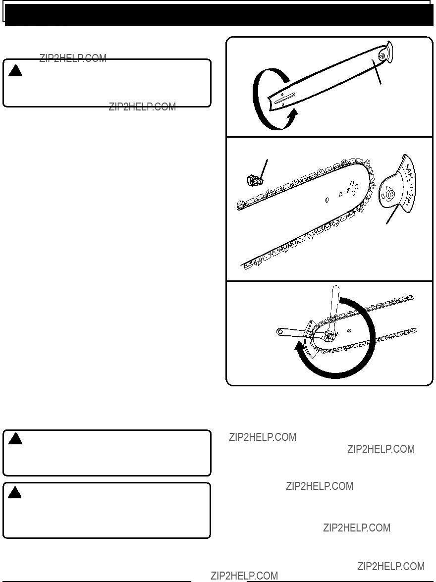


 screws
 warning:
 WARNING:
 WARNING
 WARNING:


 WARNING: