??
??
Power for the Digital Revolution.
AVR 125
AUDIO/VIDEO RECEIVER
OWNER???S MANUAL
??
??
Power for the Digital Revolution.
AVR 125
AUDIO/VIDEO RECEIVER
OWNER???S MANUAL

AVR 125 AUDIO/VIDEO RECEIVER
3Introduction
4Safety Information
4Unpacking
5
7
9
11 Remote Control Functions
14Installation and Connections
14System Installation
14Audio Equipment Connections
14Video Equipment Connections
15Power Connections
16System Configuration
16Speaker Selection and Placement
17System Setup
17Speaker Setup
18Configuring the Surround Off (Stereo) Modes
18
18Output Level Adjustment
19Delay Settings
20Additional Input Adjustments
21Operation
21Basic Operation
21Source Selection
21Volume Control
22Surround Mode Chart
23Surround Mode Selection
23Digital Audio Playback
23Selecting a Digital Source
24Digital Status Indicators
24Night Mode
25Tuner Operation
25 Tape Recording
25Output Level Trim Adjustment
26
26Display Brightness
27Programming the Remote
27Direct Code Entry
27Auto Search Method
27Code Readout
28Macro Programming
28Programmed Device Functions
28
29Volume
29 Channel Control
29 Transport Control
29 Resetting the Remote Memory
31 Function List
33 Setup Code Tables
42Troubleshooting Guide
42Processor Reset
43Technical Specifications
Typographical Conventions
In order to help you use this manual with the remote control,
EXAMPLE ??? (bold type) indicates a specific remote control or
EXAMPLE ??? (OCR type) indicates a message that is visible on the
1 ??? (number in a square) indicates a specific
?? ??? (number in a circle) indicates a
a ??? (number in an oval) indicates a button or indicator on the remote
A ??? (letter in a square) indicates an indicator in the
2 TABLE OF CONTENTS

INTRODUCTION
Thank you for choosing Harman Kardon??! With the purchase of a Harman Kardon AVR 125 you are about to begin many years of listening enjoyment. The AVR 125 has been
While complex digital systems are hard at work within the AVR 125 to make all of this happen, hookup and operation are simple.
If you have any questions about this product, its instal- lation or its operation, please contact your retailer or custom installer. They are your best local sources of information.
TO THE USER
This equipment has been tested and found to comply with the limits for a Class B digital device, pursuant to Part 15 of the FCC Rules. These limits are designed to provide reasonable protection against interference in a residential area. This device generates and uses radio frequency energy and if not installed and used in accordance with the instructions, it may cause interference to radio or TV reception.
If this unit does cause interference with TV or radio reception, you can try to correct the interference by one or more of the following measures:
A.Reorient or relocate the receiving antenna.
B.Increase the separation between the equipment and the receiver.
C.Plug the equipment into a different outlet so that it
is not on the same circuit as the receiver.
If necessary, consult the dealer or an experienced radio/TV technician for additional suggestions.
CAUTION:
Changes or modifications to this equipment not expressly approved by harman consumer group for compliance could void the user???s authority to operate this equipment.
Description and Features
The AVR 125 is among the most versatile and multi- featured A/V receivers available, incorporating a wide range of listening options. In addition to Dolby Digital and DTS decoding for digital sources, a broad choice of analog surround modes are available for use with sources such as CD, VCR, TV broadcasts and the AVR 125???s own FM/AM tuner. Along with the latest Dolby Pro Logic??* II decoding technology, Dolby 3 Stereo and custom Hall and Theater modes, only Harman Kardon receivers offer Logic 7??* to create a wider, more enveloping field environment and more defined
In addition to providing a wide range of listening options, the AVR 125 is easy to configure so that it provides the best results with your speakers and spe- cific
tailor the sound to suit your room acoustics or taste.
For the ultimate in flexibility, the AVR 125 features connections for four video devices, all with both com- posite and
Harman Kardon invented the
Pour le CANADA
CORDE DE CONNEXION CA ATTENTION:
POUR ??VITER LES CHOCS ??LECTRIQUES, INTRO-
DUIRE LA LAME LA PLUS LARGE DE LA FICHE
DANS LA BORNE CORRESPONDANTE DE LA PRISE
ET POUSSER JUSQU???AU FOND.
For CANADA
AC POWER CORD CONNECTION CAUTION:
TO PREVENT ELECTRIC SHOCK, MATCH WIDE
BLADE OF PLUG TO WIDE SLOT, FULLY INSERT.
???Onboard Dolby??* Digital and DTS??* Decoding Using Crystal??* Chip Technology
???Harman Kardon???s Exclusive Logic 7??* and VMAx?? Modes
???Dolby Laboratories??? Latest Pro Logic??* II Decoding Technology
???
???
???
???Multiple Digital Inputs and Outputs
???
???
CAUTION
RISK OF ELECTRIC SHOCK
DO NOT OPEN
CAUTION: To reduce the risk of electric shock,
do not remove cover (or back). No
Refer servicing to qualified service personnel.
The lightning flash with arrowhead symbol, within an equilateral triangle, is intended to alert the user to the presence of uninsulated ???dangerous voltage??? within the product???s
enclosure that may be of sufficient magnitude to constitute a risk of electric shock to persons.
The exclamation point within an equilateral triangle is intended to alert the user to the presence of important operating and maintenance (servicing) instructions in the
literature accompanying the appliance.
INTRODUCTION 3

SAFETY INFORMATION
Important Safety Information
Verify Line Voltage Before Use
Your AVR 125 has been designed for use with 120- volt AC current. Connection to a line voltage other than that for which it is intended can create a safety and fire hazard and may damage the unit.
If you have any questions about the voltage requirements for your specific model, or about the line voltage in your area, contact your selling dealer before plugging the unit into a wall outlet.
Do Not Use Extension Cords
To avoid safety hazards, use only the power cord attached to your unit. We do not recommend that extension cords be used with this product. As with all electrical devices, do not run power cords under rugs or carpets or place heavy objects on them. Damaged power cords should be replaced immediately by an authorized service center with a cord meeting factory specifications.
Handle the AC Power Cord Gently
When disconnecting the power cord from an AC out- let, always pull the plug, never pull the cord. If you do not intend to use the unit for any considerable length of time, disconnect the plug from the AC outlet.
Do Not Open the Cabinet
There are no
CATV or Antenna Grounding
If an outside antenna or cable system is connected to this product, be certain that it is grounded so as to pro- vide some protection against voltage surges and static charges. Section 810 of the National Electrical Code, ANSI/NFPA No.
NOTE TO CATV SYSTEM INSTALLER: This reminder is provided to call the CATV (Cable TV) system installer???s attention to article
Installation Location
???To ensure proper operation and to avoid the poten- tial for safety hazards, place the unit on a firm and level surface. When placing the unit on a shelf, be certain that the shelf and any mounting hardware can support the weight of the product.
???Make certain that proper space is provided both above and below the unit for ventilation. If this product will be installed in a cabinet or other enclosed area, make certain that there is sufficient air movement within the cabinet. Under some cir- cumstances a fan may be required.
???Do not place the unit directly on a carpeted surface.
???Avoid installation in extremely hot or cold locations, or an area that is exposed to direct sunlight or heating equipment.
???Avoid moist or humid locations.
???Do not obstruct the ventilation slots on the top of the unit, or place objects directly over them.
Cleaning
When the unit gets dirty, wipe it with a clean, soft, dry cloth. If necessary, wipe it with a soft cloth dampened with mild soapy water, then a fresh cloth with clean water. Wipe dry immediately with a dry cloth. NEVER use benzene, aerosol cleaners, thinner, alcohol or any other volatile cleaning agent. Do not use abrasive cleaners, as they may damage the finish of metal parts. Avoid spraying insecticide near the unit.
Moving the Unit
Before moving the unit, be certain to disconnect any interconnection cords with other components, and make certain that you disconnect the unit from the AC outlet.
Important Information for the User
This equipment has been tested and found to comply with the limits for a
???Reorient or relocate the receiving antenna.
???Increase the separation between the equipment and receiver.
???Connect the equipment into an outlet on a circuit different from that to which the receiver is connected.
???Consult the dealer or an experienced radio/TV tech- nician for help.
This device complies with Part 15 of the FCC Rules. Operation is subject to the following two conditions:
(1) this device may not cause harmful interference, and (2) this device must accept interference received, including interference that may cause undesired operation.
NOTE: Changes or modifications may cause this unit to fail to comply with Part 15 of the FCC Rules and may void the user???s authority to operate the equipment.
Unpacking
The carton and shipping materials used to protect your new receiver during shipment were specially designed to cushion it from shock and vibration. We suggest that you save the carton and packing materials for use in shipping if you move, or should the unit ever need repair.
To minimize the size of the carton in storage, you may wish to flatten it. This is done by carefully slitting the tape seams on the bottom and collapsing the carton. Other cardboard inserts may be stored in the same manner. Packing materials that cannot be collapsed should be saved along with the carton in a plastic bag.
If you do not wish to save the packaging materials, please note that the carton and other sections of the shipping protection are recyclable. Please respect the environment and discard those materials at a local recycling center.
At this time you should remove the protective plastic film from the
4 SAFETY INFORMATION

1 Main Power Switch
2 System Power Control
3 Power Indicator
4 Headphone Jack
5 Selector Buttons
6 Tone Mode
7 Surround Mode Selector
8 Tuning Selector
9 AM/FM Selector
) Preset Stations Selector
1 Main Power Switch: Press this button to apply power to the AVR 125. When the switch is pressed in, the unit is placed in a Standby mode, as indicated by the amber LED 3 surrounding the System Power Control 2. This button MUST be pressed in to operate the unit. To turn the unit off and prevent the use of the remote control, this switch should be pressed until it pops out from the front panel so that the word ???OFF??? may be read at the top of the switch.
NOTE: This switch is normally left in the ???ON??? position.
2 System Power Control: When the Main Power Switch 1 is ???ON,??? press this button to turn on the AVR 125; press it again to turn the unit off. Note that the Power Indicator 3 surrounding the switch will turn green when the unit is on.
3 Power Indicator: This LED will be illuminated in amber when the unit is in the Standby mode to signal that the unit is ready to be turned on. When the unit is
! Input Source Selector
@ Tuning Mode Selector
# Digital Optical 3 Input
$ Digital Coax 3 Input
% Video 3 Video Input Jacks
^ Video 3 Audio Input Jacks
& Bass Control
* Balance Control
( Treble Control
?? Volume Control
in operation, the indicator will turn green. Should the indicator turn red, turn the unit off using the Main Power Switch 1 and check the speaker wire con- nections to make certain that there are no short circuits.
4 Headphone Jack: This jack may be used to listen to the AVR 125???s output through a pair of headphones. Be certain that the headphones have a standard 1/4" stereo phone plug. The speakers will automatically be turned off when the headphone jack is in use.
5 Selector Buttons: When you are establishing the AVR 125???s configuration settings, use these buttons to select from the choices available, as shown in the Main Information Display ??.
6 Tone Mode: Pressing this button enables or dis- ables the Bass and Treble tone controls. When the button is pressed so that the words TONE IN appear in the Main Information Display ??, the
?? Set Button
??? Input Indicators
?? Delay
?? Digital Input Selector
?? Main Information Display
?? Channel Select Button
?? Speaker Select Button
?? Test Tone Selector
?? Surround Mode Indicators
?? Remote Sensor Window
settings of the Bass & and Treble ( controls may be used to adjust the output signals. When the button is pressed once or twice so that the words TONE OUT appear in the Main Information Display ??, the output signal will be ???flat,??? without any bass or tre- ble alteration, no matter how the actual Bass and
Treble Controls &( are adjusted.
7 Surround Mode Selector: Press this button to change the surround mode by scrolling through the list of available modes. Depending on the type of input, some modes are not always available. (See page 22 for more information about surround modes.)
8 Tuning Selector: Press the left side of the button to tune

In Manual tuning mode, tap the button lightly and note that the tuner will step up one frequency increment per button press. When the button is held for a few sec- onds you will note that the unit will quickly advance through the frequency band. Release it and the tuner will stop. In Auto tuning mode, each press of the but- ton will search for the next station with an acceptable signal. Press and hold the button to skip through the acceptable stations. When the button is released, the tuner will not stop until it reaches a station with an acceptable frequency.
To switch back and forth between the Auto and Manual tuning modes, press the Tuning Mode Selector @.
9 AM/FM Selector: Pressing this button will auto- matically switch the AVR 125 to the Tuner mode. Pressing it again will switch between the AM and FM frequency bands. (See page 25 for more information on the tuner.)
) Preset Stations Selector: Press this button to scroll up or down through the list of stations that have been entered into the preset memory. (See page 25 for more information on tuner presets.)
! Input Source Selector: Press this button to change the input by scrolling up or down through the list of Input Indicators ???.
@ Tuning Mode Selector: Press this button to select Auto or Manual tuning. When the button is pressed so that the AUTO Indicator R lights, the tuner will search for the next station with an acceptable signal when the Tuning Selector 8u is pressed. When the button is pressed so that the AUTO Indicator R is not lit, each press of the Tuning Selector 8u will increase the frequency. This button may also be used to switch between Stereo and Mono modes for FM radio reception. When weak reception is encountered, press the button until the STEREO Indicator P goes out to switch to Mono reception. Press and hold again to switch back to STEREO mode. (See page 25 for more information on using the tuner.)
# Digital Optical 3 Input: Connect the optical digital audio output of an audio or video product to this jack. When the input is not in use, be certain to keep the plastic cap installed to avoid dust contamination that might degrade future performance.
$ Digital Coax 3 Input: This jack is used for con- nection to the output of portable audio devices, video game consoles or other products that have a coax digital audio jack.
% Video 3 Video Input Jacks: These jacks may be used for temporary connection to the composite or S- Video output of video games, camcorders or other portable video products.
^ Video 3 Audio Input Jacks: These audio jacks may be used for temporary connection to video games or portable audio/video products such as cam- corders and portable audio players.
& Bass Control: Turn this control to modify the low- frequency output of the left/right channels by as much as ??10dB, when the unit is in the ???Surround Off??? mode. Set this control to a suitable position for your taste or room acoustics.
* Balance Control: Turn this control to change the relative volume for the front left/right channels.
NOTE: For proper operation of the surround modes this control should be at the midpoint or ???12 o???clock??? position.
( Treble Control: Turn this control to modify the high frequency output of the left/right channels by as much as ??10dB, when the unit is in the ???Surround Off??? mode. Set this control to a suitable position for your taste or room acoustics.
?? Volume Control: Turn this knob clockwise to increase the volume, counterclockwise to decrease the volume. If the AVR 125 is muted, adjusting the Volume Control ?? 33 will automatically release the unit from the silenced condition.
?? Set Button: When making choices during the setup and configuration process, press this button to enter the desired setting as shown in the Main
Information Display ?? into the AVR 125???s memory. The set button may also be used to change the display brightness. (See page 26.)
??? Input Indicators: A green LED will light in front of the input that is currently being used as the source for the AVR 125.
?? Delay: Press this button to begin the sequence of steps required to enter delay time settings. (See page 19 for more information on delay times.)
?? Digital Input Selector: When playing a source that has a digital output, press this button to select between the Optical #c and Coaxial $??
Digital inputs or to select the source???s analog input. (See pages
?? Main Information Display: This display delivers messages and status indications to help you operate
the receiver. (See pages
?? Channel Select Button: Press this button to begin the process of trimming the channel output lev- els using an external audio source. (For more informa- tion on output level trim adjustment, see page 25.)
?? Speaker Select Button: Press this button to begin the process of configuring the unit to match the type of speakers used in your listening room. (See pages
?? Test Tone Selector: Press this button to begin the process of adjusting the channel output levels using the internal test tone as a reference. (For more information on output level adjustment, see page 18.)
?? Surround Mode Indicators: A green LED will light in front of the surround mode that is currently in use.
?? Remote Sensor Window: The sensor behind this window receives infrared signals from the remote control. Aim the remote at this area and do not block or cover it.
6
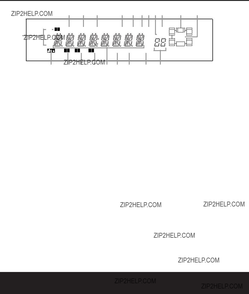
A Bitstream Indicators: When the input is a digital source, one of these indicators will light to display the spe- cific type of data signal in use.
B DTS Mode Indicator: This indicator lights when a
C Dolby Digital Indicator: This indicator lights when a Dolby Digital source is being played and Dolby Digital surround decoding is in use.
D Dolby Pro Logic II Indicator: This indicator lights when the Dolby Pro Logic II mode has been selected.
???It is possible to see the Dolby Pro Logic II indicator lit simultaneously with the Dolby Digital indicator, even though the Dolby Digital surround mode has been selected. This is due to the specifications for Dolby Digital processing, which require that the Dolby
Pro Logic II mode be used any time a
???If you desire
E Dolby 3 Stereo Indicator/Stereo Indicator: The entire indicator lights when the Dolby 3 Stereo mode has been selected. When the surround modes are turned off so that
F Main Information Display: This display shows messages relating to the status, input source, surround mode, tuner, volume level or other aspects of the
AVR 125???s operation.
G DSP Mode Indicator: This indicator lights when any of the surround modes created by Digital Signal Processing, or DSP are in use. These modes include Hall 1, Hall 2, Theater and
H VMAx Mode Indicators: This indicator lights when the VMAx mode is in use. VMAx F appears when the Far Field VMAx mode is selected; VMAx N appears when the Near Field VMAx mode is selected. (See page 22 for a description of the VMAx modes.)
I Logic 7 Mode Indicators: These indicators light when the Logic 7 mode is in use. LOGIC 7C ap- pears for the Cinema version of Logic 7; LOGIC 7M appears for the Music version of Logic 7. (See page 22 for a description of the Logic 7 modes.)
J Preset Number/Sleep Timer: When the tuner is in use, these numbers indicate the specific preset memory location in use. (See page 25 for more infor- mation on preset stations.) When the Sleep function is in use, these numbers show how many minutes remain before the unit goes into the Standby mode. (See page 21 for information on the Sleep Function.)
K Night Mode Indicator: This indicator lights when the AVR 125 is in the Night mode, which preserves the dynamic range of digital program material at low
volume levels. This mode is only available with specially encoded Dolby Digital sources. (See page 24 for a description of the Night Mode.)
L Speaker/Channel Input Indicators: These indica- tors are multipurpose, indicating either the speaker type selected for each channel or the incoming
M Preset Indicator: This indicator lights when the tuner is in use to show that the Preset Number/ Sleep Timer J is showing the station???s preset memory number. (See page 25 for more information on tuner presets.)
N Sleep Indicator: This indicator lights when the Sleep function is in use. The numbers in the Preset Number/Sleep Timer Indicators will show the minutes

remaining before the AVR 125 goes into the Standby mode. (See page 21 for more information.)
O Memory Indicator: This indicator flashes when entering presets and other information into the tuner???s memory.
P Stereo Indicator: This indicator lights when an FM station is being tuned in stereo.
Q Tuned Indicator: This indicator lights when a station is being received with sufficient signal strength to pro- vide acceptable listening quality.
R Auto Indicator: This indicator lights when the tuner???s Auto mode is in use.
S Analog Input Indicator: This indicator lights when an analog input source has been selected.
T Coaxial Digital Input Indicators: These indicators light to show when a Coaxial Digital Input has been selected.
U Optical Digital Input Indicators: These indicators light to show when an Optical Digital Input has been selected.
NOTE: See page 23 for information on assigning either an analog input or one of the digital inputs to the source currently in use.
8
??
???
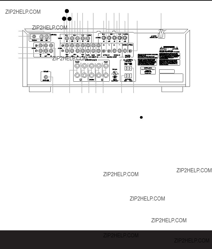
??AM Antenna: Connect the AM loop antenna sup- plied with the receiver to these terminals. If an external AM antenna is used, make connections to the AM and GND terminals in accordance with the instructions sup- plied with the antenna.
??? FM Antenna: Connect the supplied indoor or an optional external FM antenna to this terminal.
?? CD Inputs: Connect these jacks to the output of a compact disc player or CD changer.
??Tape Outputs: Connect these jacks to the RECORD/INPUT jacks of an audio recorder.
??? Tape Inputs: Connect these jacks to the PLAY/OUT jacks of an audio recorder.
?? Subwoofer Output: Connect this jack to the line- level input of a powered subwoofer. If an external sub- woofer amplifier is used, connect this jack to the sub- woofer amplifier input.
??????? Front Speaker Outputs: Connect these outputs to the matching + or ??? terminals on your front speakers. When making speaker connections, always make certain to maintain correct polarity by connecting the black terminal to the negative
(+) terminal on the left front speaker, the red terminal to the positive (+) terminal on the right front speaker and the green terminal to the positive (+) terminal on the center front speaker. Newer speakers may have matching color terminals in accordance with the new CEA specifications, while existing speakers typically use a red terminal for the positive (+) speaker wire
connection. (See page 14 for more information on speaker polarity.)
?????? Surround Speaker Outputs: Connect these outputs to the matching + or ??? terminals on your left and right surround speakers. When making speaker connections always make certain to maintain correct polarity by connecting the black terminal to the nega- tive
(+)terminal on the right surround speaker. Newer speakers may have matching color terminals in accor- dance with the new CEA specifications, while existing speakers typically use a red terminal for the positive
(+)speaker wire connection. (See page 14 for more information on speaker polarity.)

?? Switched AC Accessory Outlet: This outlet may be used to power any device you wish to have turned on or off at the same time as the AVR 125. Any device connected to this outlet will be off when the AVR 125 is in the Standby mode, and power will be supplied to the outlet when the AVR 125 is turned on.
??? Unswitched AC Accessory Outlet: This outlet may be used to power any AC device. The power will remain on at this outlet regardless of whether the AVR 125 is on or off.
IMPORTANT NOTE: The total power consumption of all devices connected to the accessory outlets should not exceed 100 watts. Do not connect power amplifiers or other
??? AC Power Cord: Connect the AC plug to an unswitched AC wall outlet.
??? Optical Digital Output: Connect this jack to the matching digital audio input connector on a digital recorder such as a
??? Coaxial Digital Output: Connect this jack to the matching digital audio input connector on a digital recorder such as a
???fVideo Monitor Outputs: Connect these jacks to the composite or
??g DVD Video Inputs: Connect one of these jacks to the composite or
?? Coaxial Digital Inputs: Connect the coax digital audio output from a DVD player, HDTV receiver, LD player, satellite receiver, cable box, MiniDisc recorder or CD player to these jacks. The signal may be either a Dolby Digital signal, DTS signal or a standard PCM digital source. Do not connect the RF digital output of an
LD player to these jacks.
ai Video 1 Video Inputs: Connect one of these jacks to the PLAY/OUT composite or
bk Video 1 Video Outputs: Connect one of these jacks to the RECORD/INPUT composite or
c Optical Digital Inputs: Connect the optical digital audio output from a DVD player, HDTV receiver, LD player, satellite receiver, cable box, MiniDisc player or recorder, or CD player to these jacks. The signal may be either a Dolby Digital signal, a DTS signal or a standard PCM digital source.
d32 Video 2 Video Inputs: Connect one of these jacks to the PLAY/OUT composite or
e
These jacks have been
h DVD Audio Inputs: Connect these jacks to the analog audio jacks on a DVD player or other source device.
NOTE: The default setting for the audio input associated with DVD is the Coaxial Digital Input 1 ??. If you connect the audio outputs of a DVD player to the ana- log jacks h, change the input setting as shown on page 20.
jVideo 1 Audio Inputs: Connect these jacks to the PLAY/OUT audio jacks on a VCR or other video source.
31 Video 1 Audio Outputs: Connect these jacks to the RECORD/INPUT audio jacks on a VCR.
33 Video 2 Audio Inputs: Connect these jacks to the PLAY/OUT audio jacks on a VCR, satellite receiver, cable box, video game or other composite video source.
10
REMOTE CONTROL FUNCTIONS
a Power Off Button
b IR Transmitter Window
c Program Indicator
d Power On Button
e Input Selectors
f AVR Selector
g AM/FM Tuner Select
h Test Button
i Sleep Button
j Surround Mode Selector
k Night Mode
l Channel Select Button
m ??? Button
n ??? Button
o Set Button
p Digital Select
q ?? Button
r Numeric Keys
s Tuner Mode
t Direct Button
u Tuning Up/Down
v Macro Buttons
w Transport Controls
x Skip Up/Down Buttons
y Disc Skip Button
z Preset Up/Down
` Clear Button
???28 Memory Button
???29 Delay/Prev. Ch.
???30 ??? Button
???31 Speaker Select
???32 Spare Button
???33 Volume Up/Down
???34 TV/Video Selector
???35
???36 Mute
NOTE: The function names shown here refer to each button???s feature when used with the AVR 125. Most buttons have additional functions when used with other devices. See pages
d
e
f
g
h
i
j
k
l
m
on p
qr
s
t
u
v
w
x
cb a
TESTT/V
SLEEP
CH. NIGHTVOL. SURR.

 125
125
36
35
34
33
32
31
30
29
28
`
z
y
REMOTE CONTROL FUNCTIONS 11

REMOTE CONTROL FUNCTIONS
IMPORTANT NOTE: The AVR 125???s remote may be programmed to control up to seven devices, including the AVR 125. Before using the remote, remember to press the Input Selector Button e that corre- sponds to the unit you wish to operate. In addition, the AVR 125???s remote is shipped from the factory to oper- ate the AVR 125 and most recent Harman Kardon products. The remote is also capable of operating a wide variety of other products using the control codes that are part of the remote. Before using the remote with other products, follow the instructions on pages
It is also important to remember that many of the but- tons on the remote take on different functions, depend- ing on the product selected using the Device Control Selectors. The descriptions shown here primarily detail the functions of the remote when it is used to operate the AVR 125. (See pages
a Power Off Button: Pressing this button turns off (places in the Standby mode) the device that was last selected by pressing one of the Input Selectors e. To place the AVR 125 in the Standby mode, first press the AVR Selector Button f and then press this button.
b IR Transmitter Window: Point this window towards the AVR 125 when pressing buttons on the remote to make certain that infrared commands are properly received.
c Program Indicator: This
d Power On Button: After selecting a device by pressing one of the Input Selectors e, press this button to turn the device on. To turn on the AVR 125, press the AVR Selector Button f.
e Input Selectors: Pressing one of these buttons will perform three actions at the same time. First, if the AVR 125 is not turned on, this will power up the unit. Next, it will select the source shown on the button as the input to the AVR 125. Finally, it will change the remote control so that it controls the device selected. After pressing one of these buttons you must press the AVR Selector Button f again to operate the AVR 125???s functions with the remote.
f AVR Selector: Pressing this button will switch the remote so that it will operate the AVR 125???s functions. If the AVR 125 is in the Standby mode, it will also turn the AVR 125 on.
g AM/FM Tuner Select: Press this button to select the AVR 125???s tuner as the listening choice. Pressing this button when the tuner is already in use will switch between the AM and FM bands.
h Test Button: Press this button to begin the sequence used to calibrate the AVR 125???s output levels. (See pages
i Sleep Button: Press this button to place the unit in the Sleep mode. After the time shown in the display, the AVR 125 will automatically go into the Standby mode. Each press of the button changes the time until
This button is also used to change channels on your TV when the TV is selected, and it is also used to end the process of creating a macro command. (See page 28 for more information on creating macros.)
j Surround Mode Selector: Press this button to begin the process of changing the surround mode. After the button has been pressed, use the ???/?? Buttons mq to select the desired surround mode. (See page 22 for more information.) This button is also used to tune channels when the TV is selected, and during the process of erasing stored macro com- mands. (See page 28 for more information on macros.)
NOTE: The Sleep Button i and Surround Mode Selector j may also function as the Channel + and ??? keys when the remote is programmed for use with TVs, cable boxes, VCRs, satellite receivers or other video devices with tuners. See page 29 for information on programming the remote for Channel Control
in AVR mode.
k Night Mode: Press this button to activate the Night mode. This mode is available in specially encod- ed digital sources to preserve dialog (center channel) intelligibility at low volume levels.
l Channel Select Button: This button is used to start the process of setting the AVR 125???s output levels to an external source. Once this button is pressed, use the ???/?? Buttons mq to select the channel being adjusted, then press the Set Button o, followed by the ???/?? Buttons mq again, to change the level setting. (See page 25 for more information.)
m ??? Button: This multipurpose button is used to change configuration settings such as output levels. When changing an item such as the surround mode or digital input directly, first press the function or mode to be changed (e.g., press the Surround Mode Selector j to select a surround mode or the Digital Select Button p to change the digital input) and then press this button to scroll through the list of available choices.
n ??? Button: This button is used to change the setting during some of the setup procedures for the AVR 125.
o Set Button: This button is used to enter settings into the AVR 125???s memory. It is also used in the setup procedures for delay time, speaker configuration and channel output level adjustment.
p Digital Select: Press this button to assign one of the digital inputs ??c#$ to the source currently in use. (See page 23 for more information on using digital inputs.)
q ?? Button: This multipurpose button is used to change configuration settings such as output levels. When changing an item such as the surround mode or digital input directly, first press the function or mode to be changed (e.g., press the Surround Mode Selector j to select a surround mode or the Digital Select Button p to change the digital input) and then press this button to scroll through the list of available choices.
r Numeric Keys: These buttons serve as a ten- button numeric keypad to enter tuner preset positions. They are also used to select channel numbers when TV has been selected on the remote, or to select track numbers on a CD, DVD or LD player, depending on how the remote has been programmed.
s Tuner Mode: Press this button when the tuner is in use to select between automatic tuning and manual tuning. In automatic tuning mode, the AUTO Indicator R will be lit, and only stations with acceptable signal quality may be tuned by pressing the Tuning Up/ Down Buttons 8u. When the button is pressed so that the AUTO Indicator R goes out, manual tuning mode is engaged, and pressing the Tuning Buttons u8 will move the frequency up or down in
t Direct Button: When the tuner is in use, press this button to start the sequence for direct entry of a station???s frequency. After pressing the button simply press the proper Numeric Keys r to select a sta- tion. (See page 25 for more information on the tuner.)
12 REMOTE CONTROL FUNCTIONS

REMOTE CONTROL FUNCTIONS
u Tuning Up/Down: When the tuner is in use, these buttons will tune up or down through the selected fre- quency band. If the Tuner Mode Button s@ has been pressed so that the AUTO Indicator R is illumi- nated, pressing either of the buttons will cause the tuner to seek the next station with acceptable signal strength for quality reception. When the AUTO Indicator R is NOT illuminated, pressing these buttons will tune sta- tions in
v Macro Buttons: Press these buttons to store or recall a ???Macro???, which is a preprogrammed sequence of commands stored in the remote. (See page 28 for more information on storing and recalling macros.)
w Transport Controls: These buttons do not have any functions for the AVR 125, but they may be pro- grammed for the forward/ reverse play operation of a wide variety of CD or DVD players, and audio or video cassette recorders. (See page 29 for more information on programming the Transport Control
x Skip Up/Down Button: These buttons have no direct function with the AVR 125, but when used with a compatibly programmed CD or DVD changer, they will change the track or chapter of the disc currently being played in the changer.
y Disc Skip Button: This button has no direct function for the AVR 125, but when used with a com- patibly programmed CD or DVD changer, it will change the disc currently being played in the changer. (See page 28 for more information on using the remote with other devices.)
z Preset Up/Down: When the tuner is in use, press these buttons to scroll through the stations pro- grammed into the AVR 125???s memory. When some source devices, such as CD players, VCRs and cas- sette decks, are selected using the device Input Selectors e, these buttons may function as Chapter Step or Track Advance.
` Clear Button: Press this button to clear incorrect entries when using the remote to directly enter a radio station???s frequency.
28Memory Button: Press this button to enter a radio station into the AVR 125???s preset memory. Once the Memory Indicator O flashes, you have five seconds to enter a preset memory location using the Numeric Keys r. (See page 25 for more information.)
29Delay/Prev Ch.: Press this button to begin
the process for setting the delay times used by the
AVR 125 when processing surround sound. After pressing this button, the delay times are entered by pressing the Set Button o and then using the ???/?? Buttons mq to change the setting. Press the Set Button o again to complete the process. (See page 19 for more information.)
30 ??? Button: Press this button to change a setting or selection when configuring many of the AVR 125???s settings.
31Speaker Select: Press this button to begin the process of configuring the AVR 125???s bass manage- ment system for use with the type of speakers used in your system. Once the button has been pressed, use the ???/?? Buttons mq to select the chan- nel you wish to set up. Press the Set Button o and then select another channel to configure. When all adjustments have been completed, press the
Set Button o twice to exit the settings and return to normal operation. (See page 17 for more information.)
32Spare Button: This button does not have any function for the operation of the AVR 125, but it is available for use when programmed with the code from another remote. (See page 27 for information on programming the remote with codes for other devices.)
33Volume Up/Down: Press these buttons to raise or lower the system volume. See page 29 for more information on programming the Volume Punch- Through capability of the remote, which allows you to change the AVR 125???s volume while the remote is set to control another device.
34TV/Video Selector: This button does not have a direct function on the AVR 125, but when used with a compatibly programmed VCR, DVD or satellite receiver that has a ???TV/Video??? function, pressing this button will switch between the output of the player or receiver and the external video input to that player. Consult the owner???s manual for your specific player or receiver for the details of how it implements this function.
35
36Mute: Press this button to momentarily silence the AVR 125 or TV set being controlled, depending on which device has been selected. When the AVR 125 is muted, press this button or use the Volume Control ?? 33 to return to the previous volume level. When the AVR 125 remote is being programmed
to operate another device or when a macro command is being programmed, this button is pressed with the
Input Selector Button e to begin the program- ming process. (See page 27 for more information on programming the remote.)
REMOTE CONTROL FUNCTIONS 13

INSTALLATION AND CONNECTIONS
System Installation
After unpacking the unit, and placing it on a solid surface capable of supporting its weight, you will need to make the connections to your audio and video equipment.
Audio Equipment Connections
We recommend that you use
When making connections to audio source equipment or speakers it is always a good practice to unplug the unit from the AC wall outlet. This prevents any possibil- ity of accidentally sending audio or transient signals to the speakers that may damage them.
1. Connect the analog output of a CD player to the
CD Inputs ??.
NOTE: When the CD player has both fixed and vari- able audio outputs it is best to use the fixed output unless you find that the input to the receiver is so low that the sound is noisy, or so high that the signal is distorted.
2.Connect the analog Play/Out jacks of a cassette deck, MD,
3.Connect the output of any digital sources to the appropriate input connections on the AVR 125 rear panel. Note that the Optical and Coaxial Digital Inputs ??c#$ may be used with a Dolby Digital or DTS source such as a DVD player, or the output of a conventional CD or LD player???s PCM
4.Connect the Optical Digital Output ??? or Coaxial Digital Output ??? on the rear panel of the AVR 125 to the matching digital input connections on a
5.Assemble the AM Loop Antenna supplied with the unit as shown below. Connect it to the AM and GND Screw Terminals ??.
6. Connect the supplied FM antenna to the FM Antenna (75 ohm) Connection ???. The FM antenna may also be an external roof antenna, an inside pow- ered or wire lead antenna or a connection from a
cable TV system. Note that if the antenna or connec- tion uses
7.If you have a
8.Connect the front, center and surround Speaker Outputs ????????????? to the respective speakers.
To ensure that all the audio signals are carried to your speakers without loss of clarity or resolution, we sug- gest that you use
Regardless of the brand of cable selected, we recom- mend that you use a cable constructed of fine, multi- strand copper with a gauge of 14 or smaller. Remember that in specifying cable, the lower the number, the thicker the cable.
Cable with a gauge of 16 may be used for short runs of less than ten feet. We do not recommend that you use cables with an AWG equivalent of 18 or higher due to the power loss and degradation in performance that will occur.
Cables that are run inside walls should have the appro- priate markings to indicate listing with UL, CSA or other appropriate testing agency standards. Questions about running cables inside walls should be referred to your installer or a licensed electrical contractor who is famil- iar with the NEC and/or the applicable local building codes in your area.
When connecting wires to the speakers, be certain to observe proper polarity. Remember to connect the ???negative??? or ???black??? wire to the same terminal on both the receiver and the speaker. The AVR 125 con- forms to the latest
color to assist you in making the correct connections. If your speakers have
While most speaker manufacturers adhere to an industry convention of using black terminals for nega- tive and red ones for positive, some manufacturers may vary from this configuration. To ensure proper phase and optimal performance, consult the identifica- tion plate on your speaker or the speaker???s manual to verify polarity. If you do not know the polarity of your speaker, ask your dealer for advice before proceeding, or consult the speaker???s manufacturer.
We also recommend that the length of cable used to connect speaker pairs be identical. For example, use the same length piece of cable to connect the
9. Connections to a subwoofer are normally made via a
Video Equipment Connections
Video equipment is connected in the same manner as audio components. Again, the use of
Although any compatible video device may be con- nected to any video input (with the exception of the
Video 1 Output Jacks bk31 , which may only be connected to a video recorder), to make programming device codes into the remote control easier, we rec- ommend that you connect your VCR to the Video 1 Connectors abijk31 , your television to the
Video 2 Connectors d32 33 , and your
1. Connect a VCR???s audio and video Play/Out jacks to the Video 1 Input Jacks aij on the rear panel. The Audio and Video Record/In jacks on the VCR
14 INSTALLATION AND CONNECTIONS

INSTALLATION AND CONNECTIONS
should be connected to the Video 1 Out Jacks bk31 on the AVR 125.
2.Connect the analog audio and video outputs of a television set or any other video source to the Video 2 Jacks d32 33 .
3.Connect the analog audio and video outputs of a cable TV converter or satellite receiver, or any other video source, to the Video 3 Jacks %^ on the front panel of the AVR 125.
4.Connect the analog audio and video outputs of
a DVD or laser disc player to the DVD Jacks ??gh. When a digital audio connection is used for your DVD player, the default connection is the
Coaxial Digital Input 1 Jack ??. However, the connection may also be made to any of the Optical c# or Coaxial ??$ Digital Inputs, provided that the digital input source selection is changed as shown on page 23. If your DVD or
5.Connect the digital audio outputs of a DVD player, satellite receiver, cable box or HDTV converter to the appropriate Optical or Coaxial Digital Inputs
??c#$.
6.Connect the Video Monitor Output ???f jacks on the receiver to the composite or
VIDEO CONNECTION NOTE:
???Composite and
AVR 125 is connected to a TV set or video display with
Power Connections
This unit is equipped with two accessory AC outlets. They may be used to power accessory devices, but they should not be used with
The Switched AC Accessory Outlet ?? will receive power only when the unit is on. This is recommended for devices that have no power switch or a mechanical power switch that may be left in the ???ON??? position.
NOTE: Many audio and video products go into a Standby mode when they are used with switched out- lets, and cannot be fully turned on using the outlet alone without a remote control command.
The Unswitched AC Accessory Outlet ??? will receive power as long as the unit is plugged into a powered AC outlet.
Finally, when all connections are complete, plug the Power Cord ??? into a nonswitched
INSTALLATION AND CONNECTIONS 15

SYSTEM CONFIGURATION
When all audio, video and system connections have been made, there are a few configuration adjustments that must be made. A few minutes spent to correctly configure and calibrate the unit will greatly add to your listening experience.
Speaker Selection and Placement
The placement of speakers in a multichannel home theater system can have a noticeable impact on the quality of sound reproduced. No matter which type or brand of speakers is used, the same model or brand of speaker should be used for the left front, center and right front speakers. This creates a seamless front soundstage and eliminates the possibility of dis- tracting sonic disturbances that occur when a sound moves across mismatched
Speaker Placement
Depending on the type of center channel speaker in use and your viewing device, place the center speaker either directly above or below your TV, or in the center behind a perforated front projection screen.
Once the center channel speaker is installed, position the left front and right front speakers so that they are as far away from one another as the center channel speaker is from the preferred listening position. Ideally, the
Depending on the specifics of your room acoustics and the type of speakers in use, you may find that imaging is improved by moving the left front and right front speakers slightly forward of the center channel speaker. If possible, adjust all front loudspeakers so that they are aimed at ear height when you are seated in the listening position.
Using these guidelines, you???ll find that it takes some experimentation to find the correct location for the front speakers in your particular installation. Don???t be afraid to move things around until the system sounds correct. Optimize your speakers so that audio transitions across the front of the room sound smooth, and that sounds from all speakers appear to arrive at the listening posi- tion at the same time (without delay from the center speaker compared to the left and right speakers).
Surround speakers should be placed on the side walls of the room, at or slightly behind the listening position. The center of the speaker should face into the room.
The speakers should be located so that the bottom of the cabinet is at least two feet higher than the listeners??? ears when the listeners are seated in the desired area.
If
Center Front Speaker
No more than 24" 
A)
No more than 6 feet when
Optional
B) The distance between the left and right speakers should be equal to the distance from the seating position to the viewing screen. You may also experiment with placing the left and right speakers slightly forward of the center speaker.
At least 6 inches from ceiling
At least 2 feet
C) Optimal placement of surround speaker
position. Again, they should be located so that the bottom of the cabinet is at least two feet higher than the listeners??? ears. The speakers should be no more than six feet behind the rear of the seating area.
Subwoofers produce nondirectional sound, so they may be placed almost anywhere in a room. Actual placement should be based on room size and shape and the type of subwoofer used. One method of find- ing the optimal location for a subwoofer is to begin by placing it in the front of the room, about six inches from a wall, or near the front corner of the room. Another method is to temporarily place the subwoofer at your normal listening position, and then walk around the room until you find a spot where the sub- woofer sounds best. Place the subwoofer in that spot. You should also follow the instructions of the sub- woofer???s manufacturer, or you may wish to experi- ment with the best location for a subwoofer in your listening room.
Once the speakers have been placed in the room and connected, the remaining steps in the setup process are to program the AVR 125???s bass manage- ment system for the type of speakers used in your system, calibrate the output levels, and set the delay times used by the surround sound processor.
You are now ready to power up the AVR 125 to begin these final adjustments.
1.Plug the Power Cord ??? into an unswitched AC outlet.
2.Press the Main Power Switch 1 in until it latches and the word ???OFF??? on the top of the switch disappears inside the front panel. Note that the Power Indicator 3 will turn amber, indicating that the unit is in the Standby mode.
3.Remove the protective plastic film from the front- panel lens. If left in place, the film may affect the performance of your remote control.
4.Install the three supplied AAA batteries in the remote as shown. Be certain to follow the (+) and
16 SYSTEM CONFIGURATION

SYSTEM CONFIGURATION
5.Turn the AVR 125 on either by pressing the
System Power Control 2 on the front panel, or via the remote by pressing the AVR Selector f or any of the Input Selectors eg 35 on the remote. The Power Indicator 3 will turn green to confirm that the unit is on, and the Main Information Display ?? will also light up.
System Setup
The AVR 125 features an advanced memory system that enables you to establish different configurations for the bass management, digital input, surround mode, delay times and output levels for each input source. This flexibility enables you to
The factory default settings for the AVR 125 have all inputs configured for an analog source (except for the DVD input, which has the Coaxial Digital Input 1 ?? as the default), Stereo as the surround mode, all speaker positions set to ???small,??? and a subwoofer con- nected. Before using the unit, you will probably want to change the settings for most inputs so that they are properly configured to reflect the use of digital or ana- log inputs, the type of speakers installed and the sur- round mode specifics. Remember that since the
AVR 125 memorizes the settings for each input indi- vidually, you will need to make these adjustments for each input used. However, once they are made, further adjustment is only required when system components are changed.
Once you have completed the settings for the first input, many settings may be duplicated for the remain- ing inputs. Remember that once the settings are entered for one input, they must be completed for all other input sources in your system.
Speaker Setup
These adjustments tell the AVR 125 which type of speakers are in use. This is important as it adjusts the settings that determine which speakers receive low- frequency (bass) information. For each of these set- tings use the LARGE setting if the speakers for a particular position are traditional
???small??? descriptions do not refer to the actual physical size of the speakers, but to their ability to reproduce
With the AVR 125 turned on, follow these steps to configure the speakers:
1.Put the AVR 125 in the Dolby Pro Logic II mode by pressing the Surround Mode Selector 7 on the front panel or by pressing the Surround Mode Selector j on the remote, until DOLBY PRO LOGIC II ??? MOVIE appears
in the Main Information Display F and the Pro Logic II Indicator D lights.
2.Press the Speaker Select Button 31 27 on the remote or front panel. FNT SPKR will appear in the Main Information Display F.
3.Press the Set Button o 21 .
4.Press the ???/??? Buttons mq on the remote or the Selector Buttons 5 on the front panel until either LARGE or SMALL appears, matching the type of speakers you have at the left- front and
When SMALL is selected,
When LARGE is selected, a
5.When you have completed your selection for the front channel, press the Set Button o 21 , and then press the ???/??? Buttons mq on the remote or the Selector Buttons 5 on the front panel to change the display to C SPKR.
6.Press the Set Button o 21 again, and use the
???/??? Buttons mq on the remote, or the Selector Buttons 5 on the front panel, to select the option that best describes your system based on the speaker definitions shown in the preceding section.
When C SMALL is selected,
When C LARGE is selected, a
will be sent to the center speaker output, and NO
NOTE: If you choose Logic 7 as the surround mode for the particular input source for which you are configuring your speakers, the AVR 125 will not make the LARGE option available for the center speaker. This is due to the requirements of Logic 7 processing, and does not indicate a problem with your receiver.
When C NONE is selected, no signals will be sent to the
7.When you have completed your selection for the center channel, press the Set Button o 21 , and then press the ???/??? Buttons n 30 on the remote or the Selector Buttons 5 on the front panel to change the display to SR SPKR.
8.Press the Set Button o 21 again, and then use the ???/??? Buttons mq on the remote or the Selector Buttons 5 on the front panel to select the option that best describes your system based on the speaker definitions shown in the preceding section.
When SR SMALL is selected,
When SR LARGE is selected, a
When SR NONE is selected, surround sound information will be split between the
9.When you have completed your selection for the surround channel, press the Set Button o 21 , and then press ???/??? Buttons mq on the remote or the Selector Buttons 5 on the front panel to change the display to
10.Press the Set Button o 21 , and then press the ???/??? Buttons mq on the remote or the Selector Buttons 5 on the front panel to select the option that best describes your system.
The choices available for the subwoofer position will depend on the settings for the other speakers, particu- larly the front left/right positions.
If the front left/right speakers are set to SMALL, the subwoofer will automatically be set to SUB, which is the ???ON??? position.
SYSTEM CONFIGURATION 17

SYSTEM CONFIGURATION
If the front left/right speakers are set to LARGE, three options are available:
???If no subwoofer is connected to the AVR 125, press the ???/??? Buttons mq on the remote so that SW NONE appears in the Main Information Display F. When this option is selected, all bass information will be routed to the front left/right ???main??? speakers.
???If a subwoofer is connected to the AVR 125, you have the option to have the front left/right ???main??? speakers reproduce bass frequencies at all times, and have the subwoofer operate only when the AVR 125 is being used with a digital source that contains a dedicated
???If a subwoofer is connected and you wish to use it for bass reproduction in conjunction with the main front left/right speakers, regardless of the type of program source or surround mode you are listen- ing to, press the ???/??? Buttons mq on the remote so that L/R+LFE appears in the
Main Information Display F. When this option is selected, a ???complete??? feed will be sent to the front left/right ???main??? speakers, and the subwoofer will receive bass frequencies below 100Hz.
11.When all speaker selections have been made, press the Set Button o 21 to return to normal operation.
Configuring the Surround Off
(Stereo) Modes
For superior reproduction of
When the analog
SURROUND OFF ??? STEREO scrolls across the Main Information Display F and the Surround Mode Indicator ?? for Surround Off is lit, the AVR 125 will pass the analog source material directly through to the front left and right speakers, bypassing the digital processing circuitry.
In this mode, the front left and right speakers will auto- matically be configured as LARGE, and it will not be possible to configure these speakers as SMALL.
You may configure the subwoofer as ON or OFF by pressing the Speaker Select Button ?? 31
until
If your front left and right speakers are not capable of handling a
Surround Mode Selector 7j until SUR- ROUND OFF ??? A/D MODE scrolls across the Main Information Display F, the Surround Mode Indicator ?? for Surround Off is lit and both the Stereo Indicator E and the DSP Mode Indicator G are lit. In this mode, the analog input will be converted to digital and routed to the digital signal processor for bass management processing before it is converted back to analog and output to the front left and right speakers.
To configure your front left and right speakers in this mode, press the Speaker Select Button ?? 31 until FNT SPKR appears in the Main Information Display F, and then press the Set Button ??o.
Press the ???/?? Buttons mq or the Selector Buttons 5 until either LARGE or SMALL appears, matching the type of speakers you have at the
When SMALL is selected,
When LARGE is selected, a
Output Level Adjustment
Output level adjustment is a key part of the configura- tion process for any surround sound product. It is par- ticularly important for a Dolby Digital receiver such as the AVR 125, as correct output levels will ensure that you hear sound tracks in their proper place with the
proper directionality and intensity.
IMPORTANT NOTE: Listeners are often confused about the operation of the surround channels. While some assume that sound should always be coming from each speaker, most of the time there will be little or no sound in the surround channels. This is because they are only used when a movie director or sound mixer specifically places sound there to create ambience, a special effect or to continue action from the front of the room to the rear. When the output lev- els are properly set, it is normal for surround speakers to operate only occasionally. Artificially increasing the volume to the rear speakers may destroy the illusion of an enveloping sound field that duplicates the way you hear sound in a movie theater or concert hall.
Before beginning the adjustment process, make cer- tain that all speaker connections have been properly made. The system volume should be set to the level that you will use during a typical listening session.
Finally, make certain that the Balance Control * is set to the center ???12 o???clock??? position.
To assist in making speaker configuration settings, the icons in the Speaker/Channel Input Indicators L change as the speaker type is selected at each posi- tion. When only the center icon box containing the abbreviation for the speaker position is lit, the speaker is set for ???small.??? When the inner box and the two outer boxes are lit, the speaker is set for ???large.??? When no indicator appears at a speaker location, that posi- tion is set for ???none??? or ???no??? speaker.
For example, in the following figure, the left front and right front speakers are set for ???large,??? the center, sur- round left (SL) and surround right (SR) speakers are set for small, and a subwoofer is set, as shown by the box with the abbreviation ???LFE???, which stands for ???low- frequency effects.???
L C R
SL LFE SR
To adjust and calibrate the output levels, follow these steps. For accurate calibration, it is a good idea to make these adjustments while seated in your favorite listening position:
18 SYSTEM CONFIGURATION

SYSTEM CONFIGURATION
1.Put the AVR 125 in the Dolby Pro Logic II mode by pressing the Surround Mode Selector 7 on the front panel, or by pressing the Surround Mode Selector j on the remote, until
DOLBY PRO LOGIC
2.Press the Test Button h on the remote. TEST FL 0dB will appear in the Main Information Display F and the letters FL will flash once each second.
3.The test noise will immediately begin to circulate among the speakers in a clockwise rotation, pausing at each position for three seconds. As the test noise rotates, the speaker position will be shown in the Main Information Display F.
NOTE: This is a good time to verify that the speakers have been properly connected. As the test noise circulates, listen to make certain that the sound comes from the speaker position shown in the Main Information Display. If the sound from a speaker location does NOT match the position indicated in the display, turn the AVR 125 off using the Main Power Switch 1 and check the speaker wiring to make certain that each speaker is connected to the correct output terminal.
4.After checking for speaker placement, let the test noise circulate, and listen to see which channels sound louder than the others. Using the front left (FL in the display) speaker as a reference, press the ???/??? Buttons mq on the remote or the Selector Buttons 5 on the front panel for each channel to begin to bring them to the same level. Note that when one of the but- tons is pushed, the test noise circulation will pause on the channel being adjusted to give you time to make the adjustment. When you release the button, the circulation will resume after 15 seconds.
5.Continue to adjust the individual speakers until they all have the same volume. Note that adjust- ments should be made with the ???/??? Buttons mq on the remote or the Selector Buttons 5 on the front panel only, NOT the main volume controls. Then press the Set Button o 21 to memorize the change. If you are using a sound pressure (SPL) meter for pre- cise level adjustment, set the volume so that the meter reads 75dB,
NOTE: The subwoofer output level is not adjustable using the test tone. To change the subwoofer level, follow the steps for Output Level Trim Adjustment on page 25.
6.When you have adjusted the output so that all channels have the same level, press the Test Button h on the remote to complete the adjustment.
Delay Settings
Due to the different distances between the
The factory setting is appropriate for most rooms, but some installations create an uncommon distance between the front and surround speakers that may cause the arrival of
To resynchronize the front and surround channels, fol- low these steps:
1.Measure the distance from the listening/ viewing position to the front speakers.
2.Measure the distance from the listening/ viewing position to the surround speakers.
3.Subtract the distance to the surround speakers from the distance to the front speakers.
a.When setting the delay time for the Dolby Digital surround mode, the optimal delay time is the result of that subtraction. For example, if the front speakers are 10 feet away and the sur- round speakers are five feet away, the optimal delay time is figured as
b.When setting the delay time for the Pro Logic II modes, take the result of the subtraction and add 15 to obtain the optimal delay time. For example, if the front speakers are 10 feet away and the surround speakers are five feet away, the optimal delay time is figured as
Pro Logic II delay should be set at 20 milli- seconds.
NOTE: The Theater and Hall modes use a fixed, non- adjustable delay time.
The Dolby Digital mode also includes a separate set- ting for the center channel delay mode, since the dis- crete nature of these signals makes the location of the center channel speaker more critical. To calculate the
delay for the center channel, measure the distance from the preferred listening position in the center of the room to both the center channel speaker and either the left or right speaker.
If the distances are equal, no further adjustment is required and the center delay should be set to zero. If the distance to the front speakers is greater than the distance to the center speaker, you may wish to repo- sition the speakers by moving the
If repositioning of the speakers is not possible, adjust the center delay time, adding one millisecond of center channel delay for every foot closer to the listening position the center speaker is than the front speaker. For example, if the
To set the delay times, follow these steps:
1.Put the AVR 125 in the Dolby Pro Logic II ??? Movies mode by pressing the Surround Mode Selector 7 on the front panel or by pressing the
Surround Mode Selector j on the remote, until DOLBY PRO LOGIC II ??? MOVIE appears in the Main Information Display F and the Pro Logic II Indicator D lights up.
2. Press the Delay Button 29 23 on the remote or front panel. The words SR DELAY will appear in the Main Information Display F.
3.Press the Set Button o 21 .
4.Adjust the delay time by pressing the ???/??? Buttons mq on the remote or the Selector Buttons 5 on the front panel until the delay time figure calculated using the formula entered above appears in the display.
5.If only analog sources will be used, no adjustment is needed for the center channel delay. In that case, press the Set Button o 21 to enter the surround delay settings into the AVR 125???s mem- ory. However, if you will be using digital sources and the calculations outlined above indicate that the center channel delay requires an adjustment, continue with the following steps.
6.Before setting the center channel delay time, make certain that a digital source has been selected.
7.Select the Dolby Digital mode by pressing either the Surround Mode Selector 7 on the front panel or the Surround Mode Selector j on the remote, until DOLBY DIGITAL appears in the Main Information Display F.
SYSTEM CONFIGURATION 19

SYSTEM CONFIGURATION
8. Press the Delay Button 29 23 on the remote or front panel. The words SR DELAY will appear in the Main Information Display F.
9.Press the Set Button o 21 , and then imme- diately press the ???/??? Buttons mq on the remote or the Selector Buttons 5 on the front panel until the desired delay time for the surround channels is shown in the display.
10. Press the Set Button o 21 within three sec- onds after the desired setting is shown.
11.Press the ???/??? Buttons mq on the remote once so that CT DELAY appears in the Main Information Display F.
12.Press the the Set Button o 21 .
13.Press the ???/??? Buttons mq on the remote or the Selector Buttons 5 on the front panel until the desired delay time for the center channel appears in the display.
14.Press the Set Button o 21 to enter the set- ting into the AVR 125???s memory.
Additional Input Adjustments
In addition to the major adjustments described in the preceding pages, you may also wish to set the type of audio source (analog or digital) to be used with an input at this time. Once a specific audio source type is associated with any of the inputs, it will remain in the memory until it is changed, even when another input is selected. To attach one of the digital inputs to a specific source, follow these steps:
1.Press the Digital Button p 24 .
2.Immediately press the ???/??? Buttons mq or Selector Buttons 5 to scroll through the list of available digital inputs or the analog input.
3.When the desired input type is shown in both the
Main Information Display F and in the Analog S, Coaxial Digital Input T or Optical Digital Input U Indicators, press the Set Button o
21 to enter the setting into the unit's memory.
When the
You may also ???memorize??? a specific surround mode so that it will always be used when an input is selected. The AVR 125 always remembers the last surround mode used with any input, but during the setup process you may wish to preset the modes for each source. To do that, follow these steps:
1.Select an input by pressing one of the Input Selectors e 35 ! or the AM/FM Tuner Select g.
2.Press the Surround Mode Selector j7, and immediately press the ???/??? Buttons mq or
Surround Mode Selector 7 to scroll through the list of available surround modes. Note that the name of each mode will scroll from right to left across the Main Information Display F. To avoid having the system ???time out??? and exit the select process, be sure to press the ???/??? Buttons mq or Surround Mode Selector 7 to select the next mode at any time the mode name is displayed.
3.When the desired mode name appears in the Main Information Display F and in the Surround Mode Indicators 29 , simply pause for a few seconds to allow the unit to ???time out.??? Your selec- tion will be memorized and will be activated each time the input is selected until another mode is selected.
4.Repeat the process for each of the inputs.
5.When the desired Surround mode has been entered for all inputs, press the Set Button o.
Once the settings outlined on the previous pages have been made, the AVR 125 is ready for operation. While there are some additional settings to be made, these are best done after you have had an opportunity to lis- ten to a variety of sources and different kinds of pro- gram material. These settings are described on pages 21 through 26 of this manual. In addition, any of the settings made in the initial configuration of the unit may be changed at any time. As you add new or dif- ferent sources or speakers, or if you wish to change a setting to better reflect your listening taste, simply fol- low the instructions for changing the settings for that parameter, as shown in this section.
Having completed the setup and configuration process for your AVR 125, you are about to experience the finest in music and home theater listening. Enjoy!
20 SYSTEM CONFIGURATION
OPERATION
Basic Operation
Once you have completed the setup and configuration of the AVR 125, it is simple to operate and enjoy. The following instructions will help you maximize the enjoy- ment of your new receiver:
Turning the AVR 125 On or Off
??? When using the AVR 125 for the first time, you must press the Main Power Switch 1 on the front panel to turn the unit on. This places the unit in a Standby mode, as indicated by the amber color of the Power Indicator 3. Once the unit is in Standby, you may begin a listening session by pressing the System Power Control 2 on the front panel or the AVR Selector f. Note that the Power Indicator 3 will turn green. This will turn the unit on and return it to the input source that was last used. The unit may also be turned on from Standby by pressing any of the Input Selector Buttons eg 35 on the remote or the
Input Source Selector ! on the front panel.
NOTE: After pressing one of the Input Selector Buttons eg 35 to turn the unit on, press the AVR Selector f to set the remote control to the AVR 125???s functions.
To turn the unit off at the end of a listening session, simply press the System Power Control 2 on the front panel or the Power Off Button a on the remote. Power will be shut off to any equipment plugged into the
When the remote is used to turn the unit ???off??? it is actually placing the system in a Standby mode, as indi- cated by the amber color of the Power Indicator 3.
??? To program the AVR 125 for automatic
The sleep time will be displayed in the Preset Number/Sleep Timer Indicator J and it will count down until the time has elapsed.
When the programmed sleep time has elapsed, the unit will automatically turn off. Note that the front panel display will dim to one half brightness when the Sleep
function is programmed. To cancel the Sleep function, press and hold the Sleep Buttoni until the infor- mation display returns to normal brightness, the
Sleep indicator numbers disappear and the words
SLEEP 0 appear in the Main Information Display F.
When you will be away from home for an extended period of time it is always a good idea to completely turn the unit off with the
NOTE: All preset memories are lost if the unit is left turned off by using the Main Power Switch 1 for more than one week.
Source Selection
???To select a source, press any of the Source Selector Buttons eg 35 on the remote.
???The input source may also be changed by pressing the
???As the input is changed, the AVR 125 will automati- cally switch to the digital input (if selected), surround mode, speaker configuration, output levels and night mode status that were entered during the configura- tion process for that source.
???The
???As the input source is changed, the new input name will momentarily appear in the Main Information Display F and a green LED will light next to the selected input???s name in the
???When an audio source is selected, the last video input used remains routed to the Video 1 Outputs bk and Video Monitor Outputs ???f. This allows you to listen to an audio input such as the tuner while watching one of the video inputs.
???When a Video source is selected, the video signal for
that input will be routed to the Video Monitor Outputs ???f and will be viewable on a TV monitor con- nected to the AVR 125.
Volume Control
???Adjust the volume to a comfortable level using the
???When listening in one of the Stereo modes with the surround circuits off, the Balance Control * may be used to adjust the relative sound output between the front left and right speakers.
???To temporarily silence all speaker outputs press the Mute Button 36 . This will interrupt the output to all speakers and the headphone jack, but it will not affect any recording or dubbing that may be in progress.
Press the Mute Button 36 again or adjust the vol- ume to return to normal operation.
???During a listening session you may wish to adjust the Bass Control & and Treble Control ( to suit your listening tastes or room acoustics.
???To set the output of the AVR 125 so that the output is ???flat,??? with the tone controls deactivated, press the
Tone Mode Button 6 until the words Tone Out appear momentarily in the Main Information Display F. To return the tone controls to an active condition, press the Tone Mode Button 6 until the words Tone In momentarily appear in the Main Information Display F.
???For private listening, plug the 1/4" stereo phone
plug from a pair of stereo headphones into the front panel Headphone Jack 4. Note that when the headphone???s plug is connected, the word HEADPHONE IN will scroll once across the
Main Information Display F and all speakers will be silenced. When the headphone plug is removed, the audio feed to the speakers will be restored.
OPERATION 21

OPERATION
Surround Mode Chart
No delay is available for this mode
22 OPERATION

OPERATION
Surround Mode Selection
One of the most important features of the AVR 125 is its ability to reproduce a full multichannel surround sound field from digital sources, analog matrix sur-
Selection of a surround mode is based on personal taste, as well as the type of program source material being used. For example, motion pictures or TV pro- grams bearing the logo of one of the major surround- encoding processes, such as Dolby Surround??*, DTS Stereo??* or UltraStereo???* may be played in either the Dolby Digital, Dolby Pro Logic II or Logic 7 Cinema sur- round modes depending on the source material.
NOTE: Once a program has been encoded with matrix surround information, it retains the surround information as long as the program is broadcast in stereo. Thus, movies with surround sound may be decoded via any of the analog surround modes such as Pro Logic II or Logic 7, when they are broadcast via conventional TV stations, cable, pay TV and satellite transmission. In addi- tion, a number of
Even when a program is not listed as carrying intentional surround information, you may find that the Pro Logic II, Logic 7, VMAx and the Hall or Theater modes often deliver enveloping surround presentations through the use of the natural information present in all stereo record- ings. However, for stereo, but not surround programs, we suggest that you experiment with the other modes.
Surround modes are selected using either the front panel controls or the remote. To select a surround mode from the front panel, press the Surround Mode Selector 7 to scroll up or down through the list of available modes. To select a surround mode using the remote, press the Surround Mode Selectorj and then press the ???/ ?? Buttons mq to change the mode. As you press the buttons, the Surround mode name will appear in the Main Information Display
F, and an individual mode indicator will also light up BCDEGHI. As the surround modes change, a green LED will light next to the current mode in the Surround Mode Indicators ?? list on the front panel.
NOTE: The name of each Surround Mode will scroll across the Main Information Display F while the modes are being selected. To avoid exiting from the surround mode selection process, push the ??? or ??? Button mq while a mode name is still visible.
The Dolby Digital and DTS modes may only be select- ed when a digital input is in use. In addition, when a digital source is present, the AVR 125 will automatical- ly select and switch to the correct mode (Dolby Digital or DTS), regardless of the mode that has been previ- ously selected. For more information on selecting digital sources, see the following section of this manual.
To listen to a program in traditional
SURR OFF appears in the Main Information Display F. The
Digital Audio Playback
Digital audio is a major advancement over older analog matrix surround systems. It delivers five discrete chan- nels:
Dolby Digital
Dolby Digital (originally known as
An optional, external RF demodulator is required to use the AVR 125 to listen to the Dolby Digital sound tracks available on laser discs. Connect the RF output of the LD player to the demodulator and then con- nect the digital output of the demodulator to the
Optical or Coaxial Inputs ??c#$ of the AVR 125. No demodulator is required for use with DVD players or
DTS
DTS is another digital audio system that is capable of delivering 5.1 audio. Although both DTS and Dolby Digital are digital, they use different methods of encoding the signals, and thus they require different decoding circuits to convert the digital signals back to analog.
#$.
In order to listen to DVDs encoded with DTS sound tracks, the DVD player must be compatible with the DTS signal as indicated by a DTS logo on the player???s front panel. Early DVD players may not be able to play
Selecting a Digital Source
To utilize either digital mode you must have properly connected a digital source to the AVR 125. Connect the digital outputs from DVD players, HDTV receivers, satellite systems or CD players to the Optical or Coaxial Inputs ??c#$. In order to provide a backup signal and a source for analog stereo record- ing, the analog outputs provided on digital source equipment should also be connected to their appropri- ate inputs on the AVR 125 rear panel (e.g., connect the analog stereo audio output from a DVD to the DVD Audio Inputs h on the rear panel when you connect the source???s digital outputs).
When playing a digital source such as DVD, first select the source input using the remote or
OPERATION 23

OPERATION
Digital Status Indicators
When a digital source is playing, the AVR 125 senses the type of bitstream data that is present. Using this information, the correct surround mode will automati- cally be selected. For example, DTS bitstreams will cause the unit to switch to DTS decoding, and Dolby Digital bitstreams will enable Dolby Digital decoding. When the unit senses PCM data from CDs or LDs, you may select any of the standard surround modes, such as Dolby Pro Logic II or Logic 7. Since the range of available surround modes is dependent on the type of digital data that is present, the AVR 125 uses a variety of indicators to let you know what type of signal is present. This will help you to understand the choice
of modes.
When a digital source is playing, a Bitstream Indicator A will light to show which type of signal is playing:
 D: When the DOLBY D indicator lights, a Dolby Digital bitstream is being received. Depending on the settings on the source player and specific surround information and number of channels on the disc, a number of surround modes are possible. For discs with full 5.1 audio, only the Dolby Digital and VMAx modes are available. When the Dolby Digital signal is only
D
DTS: When the DTS indicator lights, a DTS bitstream is being received. When the unit senses this type of data, only the DTS mode may be used.
PCM: When the PCM indicator lights, a standard Pulse Code Modulation, or PCM, signal is being received. This is the type of digital audio used by con- ventional compact disc and laser disc recordings. When a PCM bitstream is present, all modes except Dolby Digital and DTS are available.
When a
definition, a 96/24 signal may be supplied only via a digital input.
In addition to the bitstream indicators, the AVR 125 features a set of unique
These indicators are the L/C/R/SL/SR/LFE letters that are inside the center boxes of the Speaker/Channel Input Indicators L in the front panel Main Information Display ??. When a standard analog signal is in use, only the ???L??? and ???R??? indicators will light, as analog signals have only left and right chan- nels, respectively.
Digital signals, however, may have two, five or six sep- arate channels, depending on the program material, the method of transmission and the way in which it was encoded. When a digital signal is playing, the let- ters in these indicators will light in response to the specific signal being received. It is important to note that although Dolby Digital, for example, is referred to as a ???5.1??? system, not all Dolby Digital DVDs or pro- grams are encoded with 5.1 channels. Thus, it is sometimes normal for a DVD with a Dolby Digital soundtrack to trigger only the ???L??? and ???R??? indicators.
NOTE: Many DVD discs are recorded with both ???5.1??? and ???2.0??? versions of the same
The letters used by the Speaker/Channel Input Indicators L also flash to indicate when a bitstream has been interrupted. This will happen when a digital input source is selected before the playback starts, or when a digital source such as a DVD is paused. The flashing indicators remind you that the playback has stopped due to the absence of a digital signal and not through any fault of the AVR 125. This is normal, and the digital playback will resume once the playback is started again.
Night Mode
A special feature of Dolby Digital is the Night mode, which enables Dolby Digital input sources to be played back with full dialogue intelligibility while reducing the minimum peak level by 1/4 to 1/3. This prevents abruptly loud transitions from disturbing others, without reducing the impact of the digital source. The Night mode is available only when Dolby Digital signals with special data are being played.
The Night mode may be engaged when a Dolby Digital DVD is playing by pressing the Night Mode Button k on the remote. Next, press the ???/?? Buttons mq to select either the middle range or
IMPORTANT NOTES ON DIGITAL PLAYBACK:
1.When the digital playback source is stopped, or in a Pause, Fast Forward or Chapter Search mode, the digital audio data will momentarily stop, and the channel position letters inside the Speaker/ Channel Input Indicators L will flash. This is normal and does not indicate a problem with either the AVR 125 or the source machine. The AVR 125 will return to digital playback as soon as the data is available and when the machine is in a standard play mode.
2.Although the AVR 125 will decode virtually all DVD movies, CDs and HDTV sources, it is possible that some future digital sources may not be compatible with the AVR 125.
3.Note that not all digitally encoded programs contain full
4.When a digital source is playing, you may not be able to select some of the analog surround modes such as Dolby Pro Logic II, Dolby 3 Stereo, Hall, Theater or Logic 7.
5.When a Dolby Digital or DTS source is playing, it is not possible to make an analog recording using the Tape ?? and Video 1 Audio Outputs 31 . However, the digital signals will be passed through to the Optical ??? and Coaxial ??? Digital Audio Outputs.
24 OPERATION

OPERATION
PCM Audio Playback
PCM (Pulse Code Modulation) is the noncompressed digital audio system used for compact discs and laser discs. The digital circuits in the AVR 125 are capable of
Connections may be made to either the
Optical or Coaxial Inputs ??c or the
To listen to a PCM digital source, first select the input for the desired source (e.g., CD). Next, press the Digital Input Selector ??p and then use the ???/ ??
Buttons mq on the remote, or the Selector Buttons 5 on the front panel, until the desired choice appears in the Main Information Display F.
When a PCM source is playing, the PCM Indicator A will light. During PCM playback, you may select any surround mode except Dolby Digital or DTS.
If a
Main Information Display F. You may select the
Playback from PCM sources may also benefit from the Logic 7 Mode. When playing back a
NOTE: When a Logic 7 mode is in use with a Dolby Digital 2.0 digital input source, that mode, rather than Logic 7, will be used by the AVR after the digital bit- stream is interrupted for any reason such as stopping or pausing the digital playback. Note, also, that Logic 7 is not available with digital playback unless a two- channel bitstream is in use.
Tuner Operation
The AVR 125???s tuner is capable of tuning AM, FM and FM Stereo broadcast stations. Stations may be tuned manually, or they may be stored as favorite station pre- sets and recalled from a
Station Selection
1.Press the AM/FM Tuner Select Button g on the remote to select the tuner as an input. The tuner may be selected from the front panel by either pressing the Input Source Selector ! until the tuner is active or by pressing the AM/FM Band Selector 9.
2.Press the AM/FM Tuner Select Button g or AM/FM Band Selector 9 again to switch between AM and FM so that the desired frequency band is selected.
3.Press the Tuning Mode Button @ s to select manual or automatic tuning.
In automatic tuning mode, the AUTO Indicator R is illuminated in the Main Information Display ?? and the tuner will stop only at those stations that have a signal strong enough to be received with acceptable quality.
When the AUTO Indicator R is not illuminated, the tuner is in a manual mode and will stop at each frequency increment in the selected band.
4.To select stations, press the Tuning Selector Button 8u. When the AUTO Indicator R is illuminated, press the button and then release to cause the tuner to search for the next highest- or
Tuning Mode Button @s to activate the
manual mode, and tap the Tuning Selector Button 8u to advance one frequency incre- ment at a time, or press and hold it to locate a spe- cific station. When the TUNED Indicator Q lights, the station is properly tuned and should be heard with clarity.
5.Stations may also be tuned directly in either auto- matic or manual tuning mode by pressing the Direct Button t, and then pressing the Numeric Keys r that correspond to the sta- tion???s frequency. The desired station will automati- cally be tuned. If you press an incorrect button while entering a direct frequency, press the Clear Button ` to start over.
NOTE: When the FM reception of a station is weak, audio quality will be increased by switching to Mono mode by pressing the Tuning Mode Button @s until the Stereo Indicator P goes out. This will also activate manual tuning mode.
Preset Tuning
Using the remote, up to 30 stations may be stored in the AVR 125???s memory for easy recall using the front panel controls or the remote.
To enter a station into the memory, first tune the sta- tion using the steps outlined above. Then:
1.Press the Memory Button 28 on the remote. Note that the Memory Indicator O will be
illuminated and flash in the Main Information Display ??.
2.Within five seconds, press the Numeric Keys r corresponding to the location where you wish to store this station???s frequency. Once entered, the preset number will appear in the Preset Number/Sleep Time Display J.
3.Repeat the process after tuning any additional sta- tions to be preset.
Recalling Preset Stations
???To manually select a station previously entered in the preset memory, press the Numeric Keys r that correspond to the desired station???s memory
location.
???To manually tune through the list of stored preset stations one by one, press the Preset Stations Selector Buttons )z on the front panel or remote.
Tape Recording
In normal operation, the audio or video source selected for listening through the AVR 125 is sent to the record outputs. This means that any program you are watching or listening to may be recorded simply by placing machines connected to the outputs for
Tape Outputs ?? or Video 1 Outputs bk31 in the Record mode.
When a digital audio recorder is connected to the
Optical ??? or Coaxial ??? Digital Audio Outputs, you may record the digital signal using a
NOTES ON RECORDING:
???The AVR 125 converts analog inputs to a PCM digital signal, enabling you to record the material on a CD or MD recorder connected to one of the AVR 125???s Digital Audio Outputs ??????. The digital recorder must be compatible with the output signal. For example, the PCM digital input from a CD player may be recorded on a
???Please make certain that you are aware of any copyright restrictions on any material you copy. Unauthorized duplication of copyrighted materials is prohibited by federal law.
Output Level Trim Adjustment
Normal output level adjustment for the AVR 125 is established using the test tone, as outlined on pages 18 and 19. In some cases, however, it may be desir- able to adjust the output levels using program material such as a test disc, or a selection you are familiar with.
OPERATION 25

OPERATION
Additionally, the output level for the subwoofer can only be adjusted using this procedure.
To adjust the output levels using program material, first set the reference volume for the
Once the reference level has been set, press the
Channel Select Button l?? and note that FL LEVEL will appear in the Main Information Display F. To change the level, first press the Set Button o?? , and then use the Selector Buttons
5 or the ???/ ?? Buttons mq to raise or lower the level. DO NOT use the volume control, as this will alter the reference setting.
Once the change has been made, press the Set Button o?? and then press the Selector Buttons 5 or the ???/?? Buttons mq to select the next output channel location that you wish to adjust. To adjust the subwoofer level, press the
Selector Buttons 5 or the ???/?? Buttons mq until SW LEVEL appears in the Main Information Display F.
Press the Set Button o?? when the name of the desired channel appears in the Main Information Display F, and follow the instructions shown earlier to adjust the level.
Repeat the procedure as needed until all channels requiring adjustment have been set. When all adjust- ments have been made and no further adjustments are made for five seconds, the AVR 125 will return to normal operation.
NOTES:
???The output levels may be separately trimmed for each digital and analog surround mode. If you wish to have dif- ferent trim levels for a specific mode, select that mode and then follow the instructions in the steps shown earlier.
???In
The AVR 225 is equipped for future expansion through the use of optional, external adapters for formats that the AVR 225 may not be capable of processing. When an adapter is connected to the
When the
Memory Backup
This product is equipped with a memory backup system that preserves the system configuration information and tuner presets if the unit is accidentally unplugged or subjected to a power outage. This memory will last for approximately one week, after which time all information must be reentered.
Display Brightness
The AVR 125???s Main Information Display 25 is set at a default brightness that is sufficient for viewing in a normally lit room. However, in some home theater installations, you may wish to occasionally lower the brightness of the display or turn it off completely.
To change the display brightness, press and hold the Set Button ?? on the front panel for three seconds until the message in the Main Information Display
F reads VFD FULL. Within five seconds, press the Selector Buttons 5 on the front panel until the desired display brightness level is shown. At that point, press the Set Button ?? again to enter the setting.
When FULL appears in the Main Information Display F, the display is at its normal brightness. When HALF appears, the display is at half the nor- mal brightness level. When OFF appears, all of the indicators in the Main Information Display F will go dark. Note, however, that the green LEDs for the
Input Indicators 22 and the Surround Mode
Indicators 29 , as well as the Power Indicator 3 will always remain lit to remind you that the AVR 125 is still turned on.
Once the desired brightness level is selected, it will remain in effect until it is changed again or until the unit is turned off.
26 OPERATION

PROGRAMMING THE REMOTE
Programming the Remote
The AVR 125 is equipped with a powerful remote control that will control both the receiver???s functions and most popular brands of audio and video equip- ment, including CD players, cassette decks, TV sets, cable boxes, VCRs, satellite receivers and other home theater equipment. Once the AVR 125???s remote is programmed with the codes for the products you own, it is possible to eliminate most other remotes and replace them with the convenience of a single, univer- sal remote control.
As shipped from the factory, the remote is fully pro- grammed for all AVR 125 functions, as well as those of most Harman Kardon CD changers, DVD players, CD recorders, CD players and cassette decks. In addition, by following one of the methods below, you may pro- gram the remote to operate a wide range of devices from other manufacturers.
Direct Code Entry
This method is the easiest way to program your remote to work with different products.
1.Use the tables in the following pages to determine the
2.Turn on the unit you wish to program into the AVR 125 remote.
3.Press and hold both the Input Selector e for the product you wish to control (e.g., VCR, TV) and the Mute Button 36 at the same time.When the Program Indicator c turns amber and begins flashing, and the Input Selector e turns red, release the buttons. It is important that you begin the next step within 20 seconds.
4.Point the AVR 125???s remote towards the unit to be programmed and enter the first
5.If the device to be programmed in does NOT turn off, continue to enter
under the Input Selector e will flash three times before going dark to confirm the entry.
6.Try all of the functions on the remote to make cer- tain that the product operates properly. Keep in mind that many manufacturers use a number of different combinations of codes, so it is a good idea to make certain that not only the power con- trol, but the volume, channel and transport controls work as they should. If functions do not work properly, you may need to use a different remote code.
7.If a code cannot be entered to turn the unit off, if the code for your product does not appear in the tables in this manual, or if not all functions oper- ate properly, try programming the remote with the Auto Search Method.
Auto Search Method
If the unit you wish to include in the AVR 125???s remote is not listed in the code tables in this manual or if the code does not seem to operate properly, you may wish to program the correct code using the Auto Search method that follows:
1.Turn on the unit that you wish to include in the AVR 125 remote.
2.Press the Input Selector e for the type of product to be entered (e.g., VCR, TV) and the Mute Button 36 at the same time. Hold both buttons until the red light under the Input Selector e stays lit and the Program Indicator c turns amber and begins flashing. Note that the next step must take place while the red light is on, and it must begin within 20 seconds after the light appears.
3.Point the AVR 125 remote toward the unit to be programmed and press either the ??? or ?? Button mq. The Program Indicator c will change to a flashing green to indicate that a code has been entered. Each press will send out a three- digit code from the remote???s
4.Press the Input Selector e, and note that the red light under the Input Selector will flash three times before going dark to confirm the entry.
5.Try all of the functions on the remote to make cer- tain that the product operates. Keep in mind that many manufacturers use a number of different combinations of codes, and it is a good idea to make certain that not only the power control works, but also that the volume, channel and
transport controls function properly. If all functions do not work properly, you may need to Auto- Search for a different code, or enter a code via the Direct Code Entry method.
Code Readout
When the code has been entered using the Auto Search method, it is always a good idea to find out the exact code so that it may be easily reentered if neces- sary. You may also read the codes to verify which device has been programmed to a specific Control Selector button.
1.Press and hold both the Input Selector e for the device for which you wish to find the code and the Mute Button 36 at the same time. Note that the Program Indicator c will initally turn amber. Release the buttons and begin the next step within 20 seconds.
2.Press the Set Button o. The Program Indicator c will then blink green in a sequence that corresponds to the
Example: One blink, followed by a
For future reference, enter the Setup Codes for the equipment in your system here:
DVD ____________ CD ________________
VID1/VCR __________ VID2/TV ____________
VID3/CBL/SAT ________________________
VID ______________ TAPE______________
PROGRAMMING THE REMOTE 27

PROGRAMMING THE REMOTE
Macro Programming
Macros enable you to easily repeat frequently used combinations of commands with the press of a single button on the AVR 125 remote control. Once pro- grammed, a macro will send out up to 19 different remote codes in a predetermined sequential order, enabling you to automate the process of turning on your system, changing devices, or other common tasks. The AVR 125 remote can store up to five separate macro command sequences: one that is associated with the Power On Button d, and four more that are accessed by pressing the Macro Buttons v.
1.Press the Mute Button 36 and the Macro Button v to be programmed or the Power On Button d at the same time. Note that the last Input Selector e pressed will light red, and the
Program Indicator c will flash amber.
2.Enter the steps for the macro sequence by press- ing the button for the actual command step. Although the macro may contain up to 19 steps, each button press, including those used to change devices, counts as a step. The Program Indicator c will flash green to confirm each button press as you enter commands.
NOTE: While entering commands for Power On/Off of any device during a macro sequence, press the Mute Button 36 . DO NOT press the actual Power Button.
3.When all the steps have been entered, press the Sleep Button i to enter the commands. The Program Indicator c will flash green three times and then turn off.
Example: To program the Macro 1 Button v so that it turns on the AVR 125, TV and a Cable Box, follow these steps:
???Press the Macro 1 v and Mute 36 buttons at the same time and then release them.
???The Program Indicator c will flash amber.
???Press the AVR Selector f.
???Press the Mute Button 36 to store the AVR 125???s Power On command.
???Press the VID2 Input Selector Button e to indicate the next command is to be transmitted to the TV.
???Press the Mute Button 36 to store the TV Power On Command.
???Press the VID3 Input Selector Button e to indicate the next command is to be transmitted to the cable box.
???Press the Mute Button 36 to store the Cable Power On command.
???Press the Sleep Button i to complete the process and store the macro sequence.
After following these steps, each time you press the Macro 1 Button v, the remote will send the Power On/Off command to the AVR 125, the television and the cable box with a single button press.
Erasing Macro Commands
To erase the commands that have been programmed into one of the Macro buttons, follow these steps:
1.Press the Mute Button 36 and the Macro Button v that contains the commands you wish to erase.
2.The Program Indicator c will flash amber, and the LED under the AVR Selector f will turn red.
3.Within 10 seconds, press the Surround Mode Selector/Channel Down Button j.
4.The red LED under the AVR Selector f will go out, and the Program Indicator c will turn green and flash three times before it goes out.
5.When the Program Indicator c goes out, the Macro has been erased.
Programmed Device Functions
Once the AVR 125???s remote has been programmed for the codes of other devices, press the appropriate Input Selector e to change the remote from controlling the AVR 125 to controlling the additional product. When you press any one of the selectors, it will briefly flash in red to indicate that you have changed the device being controlled.
When operating a device other than the AVR 125, the controls may not correspond exactly to the function printed on the remote or button. Some commands, such as the Volume Control, are the same as they are with the AVR 125. Other buttons will change their func- tion so that they correspond to a secondary label on the remote. For example, the Sleep and Surround mode selector buttons also function as the Channel Up and Channel Down buttons when operating most TV sets, VCRs or cable boxes. The Channel Up/Down indi- cation is printed directly on the remote. For many stan- dard CD players, cassette decks, VCRs and DVD func- tions, the standard function icons are printed on top of the buttons.
For some products, however, the function of a particu- lar button does not follow the command printed on the remote. In order to see which function a button controls, consult the Function List tables on pages 31 and 32 To use those tables, first check the type of device being controlled (e.g., TV, VCR). Next, look at
the remote control diagram pictured just before the Function List tables. Note that each button has a num- ber on it.
To find out what function a particular button has for a specific device, find the button number on the Function List and then look in the column for the device you are controlling. For example, button num- ber 50 is the Macro 2 button for the AVR 125, but it
is the ???Favorite??? button for many cable television boxes and satellite receivers. Button number 29 is the Delay button for the AVR 125, but the Time Display button for CD players.
NOTE: The numbers used to describe the button functions in the diagram on page 30 for the purposes of describing how a button operates are a different set of numbers than those used in the rest of this manual to describe the button functions for the AVR 125.
Notes on Using the AVR 125 Remote
With Other Devices
???Manufacturers may use different code sets within the same product category, such as TV sets or VCRs. They may also change codes for a certain category from one model year to the next. For that reason, it is important that you check to see whether the code set you have entered operates as many controls as possible. If it appears that only a few functions operate, check to see whether another code set will work with more buttons.
???When a button is pressed on the AVR 125 remote, the red light under the Input Selector e for the product being operated should flash briefly. If the Device Control Selector flashes for some but not all buttons for a particular product, it does NOT indi- cate a problem with the remote but rather that no function is programmed for the button being pushed.
The AVR 125's remote may be programmed to con- trol one device, such as a TV, while simultaneously directing only certain functions to another device, such as the transport controls of a DVD player, without hav- ing to switch back and forth between inputs. You may also use the remote to control the system volume on the AVR without the need to switch between different devices. This is called
NOTE: All programming for the rem codes needed to operate specific devices, such as a TV, DVD, cable box, satellite receiver or VCR, should be completed before programming
28 PROGRAMMING THE REMOTE

PROGRAMMING THE REMOTE
Volume
The AVR 125???s remote may be programmed to oper- ate the Volume Control 33 and Mute 36 func- tions of either the TV or the AVR 125 in conjunction with any of the devices controlled by the remote. For example, since the AVR 125 will likely be used as the sound system for TV viewing, you may wish to have the AVR 125???s volume activated, although the remote is set to run the TV. Either the AVR 125 or TV volume control may be associated with any of the remote???s devices. To program the remote for Volume Punch- Through, follow these steps:
1.Press the Input Selector e for the unit you will be using (e.g., TV) when you wish to have Volume
2.Press the Volume Up Button 33 and note that the Program Indicator c will stop flashing and stay amber.
3.Press either the AVR Selector f or the Input Selector e, depending on which system???s volume control you wish to have attached for the
Example: To have the AVR 125???s volume control activated even though the remote is set to control the TV, first press the Video/TV Input Selector e and the Mute Button 36 at the same time. Next, press the Volume Up Button 33 , followed by the AVR Input Selector f.
NOTE: Should you wish to return the remote to the original configuration after entering a Volume Punch- Through, you will need to repeat the steps shown above. However, press the same Input Selector in Steps 1 and 3.
Channel Control
The AVR 125???s remote may be programmed to operate so that the channel control function for either the TV, cable or satellite receiver used in your system may be used in conjunction with one of the other devices con- trolled by the remote. For example, while using and con- trolling the VCR, you may wish to change channels on a cable box or satellite receiver without having to change the device selected by the AVR 125 or the remote. To program the remote for Channel Control
1.Press the Input Selector Button e for the device you will be using (e.g., VCR) when you wish to have Channel
Button 36 at the same time until the red light appears under the Input Selector e and the
Program Indicator c flashes amber.
2.Press the Volume Down Button 33 . The
Program Indicator c will stop flashing and stay amber.
3.Press and release the Input Selector Button e for the device that will be used to change the chan- nels. The Program Indicator c will blink green three times and then go out to confirm the data entry.
Example: To control the channels using your Cable Box or Satellite Receiver while the remote is set to control the VCR, first press the VID1/VCR Input Selector Button e and the Mute Button 36 at the same time. Next, release them and press the
Volume Down Button 33 , followed by the VID2/TV Input Selector Button e.
NOTE: To remove the Channel Control
Transport Control
The AVR 125???s remote may be programmed to operate so that the Transport Control Functions w (Play, Stop, Fast Forward, Rewind, Pause and Record) for a VCR, cassette deck, DVD or CD will operate in conjunc- tion with one of the other devices controlled by the remote. For example, while using and controlling the TV, you may wish to start or stop your VCR or DVD without having to change the device selected by the AVR 125 or the remote. To program the remote for Transport Control
1.Press the Input Selector e for the device you will be using (e.g., TV) when you wish to have Transport Control
Program Indicator c flashes amber.
2.Press the Play Button w. The Program Indicator c will stop flashing and stay amber.
3.Press and release the Input Selector Button e for the device whose transport mechanism will be controlled (e.g., DVD, CD). The Program Indicator c will blink green three times and then go out to confirm the data entry.
Example: To control the transport of a DVD player while the remote is set to control the TV, first press the
VID2/TV Input Selector Button e and the Mute Button 36 at the same time. Next, release them and press the Play Button w, followed by the
DVD Input Selector Button e.
NOTE: To remove the Channel Control
Resetting the Remote Memory
As you add components to your home theater system, occasionally you may wish to totally reprogram the remote control without the confusion of any commands, macros or
1.Press any of the Input Selector Buttons e and the ???O??? Button r at the same time until the Program Indicator c begins to flash amber.
2.Press the ???3??? Button r three times.
3.The red LED under the Input Selector e will go out and the Program Indicator c will stop flash- ing and turn green.
4.The Program Indicator c will remain green until the remote is reset. Note that this may take a while, depending on how many commands are in the memory and need to be erased.
5.When the Program Indicator c goes out, the remote has been reset to the factory settings.
PROGRAMMING THE REMOTE 29

PROGRAMMING THE REMOTE

 125
125
The diagram on this page shows the button numbers used in the Function List tables on pages
30 PROGRAMMING THE REMOTE
FUNCTION LIST
FUNCTION LIST 31

FUNCTION LIST
32 FUNCTION LIST

SETUP CODE TABLE: TV
SETUP CODES 33

SETUP CODE TABLE: TV
34 SETUP CODES

SETUP CODE TABLE: TV/VCR
SETUP CODE TABLE: VCR
SETUP CODES 35

SETUP CODE TABLE: VCR
36 SETUP CODES

SETUP CODE TABLE: CD
SETUP CODES 37

SETUP CODE TABLE: CD/DVD
SETUP CODE TABLE: DVD
38 SETUP CODES

SETUP CODE TABLE: SAT
SETUP CODES 39

SETUP CODE TABLE: TAPE/CBL
SETUP CODE TABLE: CBL
40 SETUP CODES
SETUP CODE TABLE: CBL
SETUP CODES 41

TROUBLESHOOTING GUIDE
Your AVR 125 receiver has been designed to provide many years of
No sound from any speaker; light around power switch is red
???Amplifier is in protection mode due to possible short
???Amplifier is in protection mode due to internal problems
???Check speaker wire connections for shorts at receiver and speaker ends
???Contact your local Harman Kardon service center, which you can locate by visiting our Web site at www.harmankardon.com
Processor Reset
In the rare case where the unit???s operation or the displays seem abnormal, the cause may involve the erratic operation of the system???s memory or micro- processor.
To correct this problem, first unplug the unit from the AC wall outlet and wait at least three minutes. After the pause, reconnect the AC power cord and check the unit???s operation. If the system still malfunctions, a sys- tem ???reset??? may clear the problem.
To clear the AVR 125???s entire system memory includ- ing tuner presets, output level settings, delay times and speaker configuration data, first put the unit in Standby by pressing the System Power Control Button 2.
Next, press and hold the Tone Mode 6 button for three seconds.
The unit will turn on automatically and display the
RESET message in the Main Information Display F. Note that once you have cleared the memory in this manner, it is necessary to reestablish all system configuration settings and tuner presets.
The reset will not affect settings that were programmed into the remote control. To reset the remote control and restore it to its factory default settings, please follow the instructions on page 29.
If these steps do not solve the problem, consult an authorized Harman Kardon service center. You can locate the service center nearest to you by visiting our Web site at www.harmankardon.com.
Memory Backup
This product is equipped with a memory backup sys- tem that preserves the system configuration informa- tion and tuner presets if the unit is accidentally unplugged or subjected to a power outage. This mem- ory will last for approximately one week, after which time all information must be reentered.
42 TROUBLESHOOTING GUIDE

TECHNICAL SPECIFICATIONS
Audio Section
Stereo Mode
Continuous Average Power (FTC)
55 Watts per channel, @ < 0.07% THD, 20Hz ??? 20kHz, both channels driven into 8 ohms
Power Per Individual Channel
Front L&R channels: 45 Watts per channel
@ < 0.07% THD,
Center channel:
45 Watts @ < 0.07% THD,
Surround channels: 45 Watts per channel
@ < 0.07% THD,
Depth measurement includes knobs, buttons and terminal connections.
Height measurement includes feet and chassis.
All features and specifications are subject to change without notice.
*See the following trademark acknowledgements:
Harman Kardon and Power for the Digital Revolution are registered trademarks of Harman Kardon, Inc.
Manufactured under license from Dolby Laboratories. ???Dolby,??? ???Pro Logic??? and the
???DTS??? and ???DTS Digital Surround??? are registered trademarks of Digital Theater Systems, Inc. UltraStereo is a trademark of UltraStereo Corp.
VMAx is a registered trademark of Harman International Industries, Inc., and is an implementation of Cooper Bauck Transaural Stereo under patent license.
Logic 7 is a registered trademark of Lexicon, Inc., a Harman International Company, and Harman International Industries, Inc..
Crystal is a registered trademark of Cirrus Logic Corp.
TECHNICAL SPECIFICATIONS 43

??
250 Crossways Park Drive, Woodbury, New York 11797 www.harmankardon.com
?? 2002 Harman Kardon, Incorporated Part No.: CQX1A778Z


??
AVR 125
??
Power for the Digital Revolution.
Thank you for purchasing a Harman Kardon AVR 125. This
Figure 1 ??? Speaker Placement
The colors shown for each speaker correspond to the matching output terminal connection on the back of the AVR 125 (see page 14).
Connections Color Guide
Front
Center
Surround
Subwoofer
Digital Audio Connections
Coax
Optical
Video Connections
Composite
Match the colored jacks on the AVR 125 to the appropriate jacks on your source equipment or speakers. The colors are standardized, but not all equipment or connectors use them.
SURROUND
LEFT
SPEAKER
(Blue)
Step 1. Place your speakers in the listening room (see page 16).
SPEAKER PLACEMENT

??
??
Power for the Digital Revolution.
AVR 125

 , 1A
, 1A 


 , 0.5A

Step 2. Connect the speakers to the receiver: red (+) on speaker to colored (+) on receiver and black
Step 3. Connect the Subwoofer
Figure 2 ??? Speaker Connections
Figure 3 ??? How to Use the
Speaker Terminal


 , 1A
, 1A 

 , 0.5A

REC/IN
PLAY/OUT
AUDIO RECORDER
Figure 4 ??? Audio Connections
Dashed lines (??? ??? ???
Step 4. Connect AM and FM antennas (as shown above). (See page 14.) Step 5. Connect source components, as shown in Figures 4 and 5, and the
Device Connection Options chart on the back of this Guide (see pages 14
AUDIO connections: Right channel (red) on source to right (red) on AVR, and left channel (white) on source to left (white) on AVR.
DIGITAL AUDIO connections, if available: Choose either coax (orange) to coax (orange) OR optical to optical for each device. The Coax 1 input defaults to the DVD player, but may be reassigned. Assign the other digital inputs and outputs as appropriate for your equipment (see Step 7).
VIDEO connections: Choose either composite (yellow) or
Monitor outputs to your Video Monitor (TV). Switch your TV set???s input to match the type of video used for the currently selected source.
Step 6. Plug all components into AC power outlets. The outlets on the back of the AVR 125 should be used only for
Basic Receiver Configuration
Step 7. Select digital inputs: If your DVD is connected to Coax 1, no adjust- ment is needed. For any other
Step 8. Select a surround mode: Press the Surround Mode button on the front panel to select Dolby?? Pro Logic?? II ??? Movie. (You may select other modes later as you become familiar with the AVR 125; see
pages 17, 20 and
Step 9. Configure speakers: No action is needed if you have five ???small???
Step 10. Set output levels: Set the Balance to 12 o???clock, and the Volume to
Step 11. Your system is configured ??? sit back and enjoy!
SPEAKER AND VIDEO CONNECTIONS

Cable or Sat or HDTV
IN
OUT
Optical Coax
Harman International Industries, Incorporated Part No.: CQE1A188Z

 , 1A
, 1A 

 , 0.5A

FRONT PANEL
York 11797 www.harmankardon.com ?? 2002
Figure 5 ??? Video Connections
Dashed lines (??? ??? ???
Dotted lines (????????????) indicate composite or
Crossways Park Drive, Woodbury, New
Device Connection Options: Recommended connections are shown in red, but connections may be made to best fit your system requirements. The Video 3 inputs are on the front panel of the receiver.
*Check with your cable company to determine whether digital audio is available for all channels. It may be necessary to make BOTH analog and digital connections if it is not. **Digital audio recorders only.
250
??
VIDEO CONNECTIONS
??
Power for the Digital Revolution.