AVR 1650/AVR 165
Audio/video receiver
Owner???s Manual
AVR 1650/AVR 165
Audio/video receiver
Owner???s Manual
AVR 1650/AVR 165
Table of Contents
2
AVR 1650/AVR 165
Introduction
Thank you for choosing this Harman Kardon product!
For more than ???fty years, the Harman Kardon mission has been to share a passion for music and entertainment, using
The AVR 1650 and AVR165
To obtain the maximum enjoyment from your new AVR, please read this manual and refer back to it as you become more familiar with its features and their operation.
If you have any questions about this product, its installation or its operation, please contact your Harman Kardon retailer or custom installer, or visit our Web site at www. harmankardon.com.
Supplied Accessories
The following accessory items are supplied with your AVR. If any of these items are missing, please contact your Harman Kardon dealer, or Harman Kardon customer service at www.harmankardon.com.
???System remote control
???EzSet/EQ??? microphone
???AM loop antenna
???FM wire antenna
???Three AAA batteries
???AC power cord
Introduction, Supplied Accessories,
Important Safety Information and Place the AVR
IMPORTANT SAFETY INFORMATION
Verify Line Voltage Before Use
The AVR 1650 has been designed for use with
Do Not Use Extension Cords
To avoid safety hazards, use only the power cord supplied with your unit. We do not recommend that extension cords be used with this product. As with all electrical devices, do not run power cords under rugs or carpets, or place heavy objects on them. Damaged power cords should be replaced immediately by an authorized service center with a cord meeting factory speci???cations.
Handle the AC Power Cord Gently
When disconnecting the power cord from an AC outlet, always pull the plug; never pull the cord. If you do not intend to use your AVR for any considerable length of time, disconnect the plug from the AC outlet.
Do Not Open the Cabinet
There are no
CATV or Antenna Grounding (AVR 1650)
If an outside antenna or cable system is connected to this product, be certain that it is grounded so as to provide some protection against voltage surges and static charges. Section 810 of the United States National Electrical Code, ANSI/NFPA No.
NOTE TO CATV SYSTEM INSTALLER: This reminder is provided to call the CATV (cable TV) system installer???s attention to article
Place the AVR
???Place the AVR on a ???rm and level surface. Be certain that the surface and any mounting hardware can support the AVR???s weight.
???Provide proper space above and below the AVR for ventilation. If you install the AVR in a cabinet or other enclosed area, provide cooling air within the cabinet. Under some circumstances, a fan may be required.
???Do not obstruct the ventilation slots on the top of the AVR or place objects directly over them.
???Do not place the AVR directly on a carpeted surface.
???Do not place the AVR in moist or humid locations, in extremely hot or cold locations, in areas near heaters or heat registers, or in direct sunlight.
3

AVR 1650/AVR 165
4

AVR 1650/AVR 165
Power indicator: This LED has three possible modes:
???LED is off: Indicates that the AVR is unplugged or the
???LED glows amber: Indicates that the AVR is in the Standby mode.
???LED glows white: Indicates that the AVR is turned on.
IMPORTANT NOTE: If the PROTECT message ever appears on the AVR???s
IR sensor: This sensor receives infrared (IR) commands from the remote control. It is important to ensure that the sensor is not blocked.
Set button: Press this button to select the currently highlighted menu item.
Message display: Various messages appear in this
Volume knob: Turn this knob to raise or lower the volume.
Up/Down buttons: Use these buttons to navigate the AVR???s menus.
Volume knob: Turn this knob to raise or lower the volume.
Power button: Press this button to turn the AVR on or to place it in the Standby mode.
Tuning Mode button: This button toggles between manual (one frequency step at a time) and automatic (seeks frequencies with acceptable signal strength) tuning mode. It also toggles between stereo and mono modes when an FM station is tuned in.
Channel Level Control button: Press this button to activate the
Digital Input button: Press this button to change the audio input for the current source. Use the Left/Right buttons to cycle through the available inputs. Although you can assign any digital audio input to any source, the analog audio inputs are all permanently dedicated to the source with which they are labeled.
Left/Right buttons: Use these buttons to navigate the AVR???s menus.
Up/Down buttons/Tuning buttons: Use these buttons to navigate the AVR???s menus. When the radio is the active source, use these buttons to tune stations according to the setting of the Tuning Mode button (see above).
category. Each press changes the
Headphone jack/EzSet/EQ Mic connector: Connect a 1/4" stereo headphone plug to this jack for private listening. This jack is also used to connect the supplied microphone for the EzSet/EQ procedure described in Con???gure the AVR for Your Speakers, on page 17.
Source Select buttons: Press these buttons to select the active source.
USB port: You can use this port to perform software upgrades that may be offered in the future. Do not connect a storage device, a peripheral product or a PC here, unless instructed to do so as part of an upgrade procedure.
Aux Analog Audio Input connector: Connect an auxiliary source component that will be used only temporarily, such as a camcorder, portable music player or game console, here.
5

AVR 1650/AVR 165
AVR 1650/AVR 165
6

AVR 1650/AVR 165
Radio Antenna connectors: Connect the included AM and FM antennas to their respective terminals for radio reception.
HDMI Monitor Out connector: If your TV has an HDMI connector and you have HDMI or component video source devices, use an HDMI cable (not included) to connect it to the AVR???s HDMI Monitor Out connector.
Notes on using the HDMI Monitor Out connector:
???When connecting a
???Make sure the
HDMI Input connectors: The HDMI
Composite Video Monitor Out connector: If your TV or video display does not have an HDMI connector, or if your TV does have an HDMI connector but you are connecting some source devices with only composite video connectors, use a composite video cable (not included) to connect the AVR???s Composite Video Monitor Out connector to your TV???s composite video input connector.
DVD Component Video Input connector: If your
Digital Audio Input connectors: If your
connect them to the AVR???s digital audio connectors. NOTE: Make only one type of digital connection (HDMI, optical or coaxial) from each device. See Connect Your Source Devices, on page 13, for more information.
Video 2 Out connector: Connect an analog video recorder???s video input connector to the
AVR???s Video 2 Out connector. You can record any composite video input signal. NOTE: To record the audio and video from the source device, connect the AVR???s Video 2 Out Analog Output connectors to the analog video recorder???s audio inputs.
Composite Video Input connectors: Use composite video connectors for video source devices that don???t have HDMI or component video connectors. You will also need to make an audio connection from the source device to the AVR. See Connect Your Source Devices, on page 13, for more information.
IR Remote In/Out connectors: When the IR Sensor on the front panel is blocked (such as when the AVR is installed inside a cabinet), connect an optional IR receiver to the IR Remote In connector. The IR Remote Out connector may be connected to the IR input of a compatible product to enable remote control through the AVR. See Connect IR Equipment, on page 15, for more information.
The Bridge IIIP connector: Connect an optional Harman Kardon The Bridge IIIP docking station to this connector. Insert the plug until it snaps into place in the connector. IMPORTANT: Connect The Bridge IIIP only with the AVR???s power turned off. See Connect The Bridge IIIP, on page 15, for more information.
Subwoofer connector: Connect this jack to a powered subwoofer with a
Analog Audio Input/Output connectors: Use the AVR???s Analog Audio Input/Output connectors for source devices that don???t have HDMI or digital audio connectors. Use the Video 2 Out and Tape Out connectors to connect to the audio inputs of a VCR and tape deck. See Connect Your Source Devices, on page 13, for more information.
Speaker connectors: Use
Optical Digital Output connector: Connect a digital audio recorder???s optical digital input to the AVR???s Optical Digital Output connector. You can record both coaxial and optical digital PCM audio signals. (Dolby Digital and DTS?? bitstreams are not available for recording.)
Main Power switch: This mechanical switch turns the AVR???s power supply on or off. It is usually left on and cannot be turned on or off using the remote control.
12V Trigger connector: This connector provides 12V DC whenever the AVR is on. It can be used to turn on and off other devices such as a powered subwoofer.
AC Input connector: After you have made all other connections, plug the supplied AC power cord into this receptacle and into an unswitched wall outlet.
7
AVR 1650/AVR 165
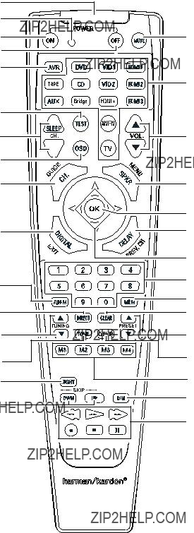
System Remote Control Functions
System Remote Control Functions
IR Transmitter Lens
Program Indicator LED
Power On Button
Power Off Button
AVR Button
Test Tone Button
Sleep/CH Up/Down Buttons
OSD Button
Channel Level Control Button
Digital Input Button
Direct Station Entry Button
Tuning Up/Down Buttons
Tone Control Button
Night Mode Button
Track Skip Up/Down Buttons
Mute Button
Source Selector Buttons
Volume Up/Down Buttons
Speaker Setup Buttons
OK Button
Delay Button
Left/Right/Up/Down Buttons
Number Buttons
Memory Button
Clear Button
Preset Station Up/Down Buttons
Disc Skip Button (AVR 1650)
RDS Button (AVR 165)
Macro Buttons
Display Dimmer Button
Transport Control Buttons
8
AVR 1650/AVR 165
System Remote Control Functions, continued
System Remote Control Functions, continued
In addition to controlling the AVR, the AVR remote is capable of controlling nine other devices, including an iPod/iPhone device docked in a The Bridge IIIP docking station connected to the AVR. During the installation process, you may program the codes for each of your source components into the remote. (See Program the Remote to Control Your Source Devices and TV, on page 16, for programming information.) To operate a component, press its Source Selector button to change the remote???s control mode.
A button???s function depends on which component is being controlled. See Table A10 in the Appendix for listings of the functions for each type of component. Most of the buttons on the remote have dedicated functions, although the precise codes transmitted vary depending on the speci???c device being controlled. Due to the wide variety of functions for various source devices, we have included only a few of the most
IR Transmitter lens: As buttons are pressed on the remote, infrared codes are emitted through this lens.
Program Indicator LED: This LED lights up to indicate various procedures when the remote is in the Programming mode.
Power On/Off buttons: Press these buttons to turn the AVR or the device being controlled on and off. The Main Power switch on the AVR???s rear panel must be on for this button to turn the AVR on and off.
Mute button: Press this button to mute the AVR???s
AVR button: Press this button to switch the remote???s control mode to operate the AVR.
Source Selector buttons: Press one of these buttons to select a source device, e.g., DVD, AM/FM radio, etc. This action will also turn on the AVR and switch the remote???s control mode to operate the selected source device. NOTE: The ???rst press of the Radio Source Selector button switches the AVR to the
Test Tone button: Press this button to activate the test tone for calibrating channel volume levels by ear.
Sleep button/Channel Up/Down buttons: Press the Sleep button to activate the sleep timer, which turns off the AVR after a programmed period of time of up to 90 minutes. The Channel Up/Down buttons have no effect on the AVR but are used to change channels on TVs and some video sources.
Volume Up/Down buttons: Press these buttons to raise or lower the volume.
OSD button: Press this button to activate the
Channel Level Control button: Press this button to activate the individual
Speaker Setup button: Press this button to con???gure which speakers are included in your system. See Manual Speaker Setup, on page 21, for more information.
OK button: This button is used to select items from the menu system.
Digital Input button: Press this button to select the speci???c digital audio input (or analog audio input) to which the current source is connected.
Delay button: Pressing this button lets you adjust two different types of delay settings (use the Up/Down buttons to cycle through the settings):
???A/V Sync: This setting lets you resynchronize the audio and video signals from a source to eliminate a ???lip sync??? problem.
???Front L/Center/Front R/Surr R/Surr L/Subwoofer: These settings let you set the delay for each speaker to compensate for the different distances they may be from the listening position. Use the Up/Down buttons to cycle through each of the system???s speakers, and use the Left/Right buttons to set the distance each speaker is from the listening position. See Manual Speaker Setup, on page 21, for more information.
Left/Right/Up/Down buttons: These buttons are used to navigate the menu system.
Number buttons: Use these buttons to enter numbers for
Tuning Mode button: Press this button to toggle the radio between manual (one frequency step at a time) and automatic (seeks frequencies with acceptable signal strength) tuning mode. It also toggles between stereo and mono modes when an FM station is tuned in.
Memory button: To save the currently tuned radio station as a preset, press this button, then a Number button.
Direct Station Entry button: Press this button before using the Number buttons to enter a radio station frequency.
Clear button: Press this button to clear a radio station frequency you have started to enter.
Tuning Up/Down buttons: Press these buttons to tune a radio station. Depending on whether the tuning mode has been set to manual or automatic, each press will either change one tuning frequency increment at a time or seek the next higher or lower station with acceptable signal strength.
Preset Station Up/Down buttons: Press these buttons to cycle through your preset radio stations.
Tone Control button: Press this button to access the bass and treble controls. Use the OK button to select an adjustment and use the Up/Down buttons to change the settings.
Disc Skip button (AVR 1650): This button is used with some optical disc changers to skip to the next disc.
RDS button (AVR 165): When listening to an FM radio station that broadcasts RDS information, this button activates the various RDS functions.
Night Mode button: Press this button to activate Night mode with specially encoded Dolby Digital discs or broadcasts. Night mode compresses the audio so that louder passages are reduced in volume to avoid disturbing others, while dialogue remains intelligible. Each press of the button advances through the following settings:
???Off: No compression is applied. Loud passages in the program remain as they were recorded.
???Mid: Loud passages in the program are reduced moderately in volume.
???Max: Loud passages in the program are reduced more in volume.
Macro buttons: These buttons may be programmed to execute a series of up to 19 commands with a single button press. They are useful for programming the command to turn on or off all of your components or for accessing specialized functions for a different component from the one that you are currently operating. See Programming Macro Commands, on page 24, for information about programming macros.
Track Skip Up/Down buttons: These buttons have no effect on the AVR but are used with many source components to change tracks or chapters.
Display Dimmer button: Press this button to dim the AVR???s
Transport Control buttons: These buttons have no effect on the AVR but are used to control many source components. By default, when the remote is operating the AVR, these buttons will control a Harman Kardon
9

AVR 1650/AVR 165
Introduction to Home Theater and Place Your Speakers
This introductory section will help you to familiarize yourself with some basic concepts unique to multichannel
Typical Home Theater System
A home theater typically includes an audio/video receiver (AVR), which controls the system and supplies ampli???cation for the loudspeakers; a disc player; a source component for television broadcasts (cable box, satellite dish AVR, HDTV tuner or antenna connected to the TV); a TV or video display; and multiple loudspeakers.
Multichannel Audio
The main bene???t of a home theater system is its ability to produce ???surround sound.??? Surround sound uses multiple speakers and ampli???er channels to immerse you in the audio/video presentation for a dramatically increased sense of realism.
Your AVR can have up to ???ve main speakers connected directly to it, plus a subwoofer. Each main speaker is powered by its own ampli???er channel inside the AVR. A system with more than two speakers is called a multichannel system. The different main speaker types in a home theater system are:
???Front Left and Right: The front left and right speakers are used as in a
???Center: When you are watching movies and television programs, the center speaker reproduces most of the dialogue and other soundtrack information that occurs on the screen, anchoring it with the picture. When you are listening to a musical program, the center speaker helps to create a seamless front soundstage, creating a more realistic
???Surround Left and Right: The surround left and right speakers produce ambient sounds that help create a realistic and immersive
Many people expect the surround speakers to play as loudly as the front speakers. Although you will calibrate all of the speakers in your system to sound equally loud at the listening position, most artists use the surround speakers for ambient effects only, and they create their programs to steer relatively little sound to these speakers.
???Subwoofer: A subwoofer is designed to play only the lowest frequencies (the deep bass). It augments smaller,
Surround Modes
There are different theories as to the best way to present surround sound and to distribute the individual channel information to the
???Dolby Laboratories: Dolby TrueHD, Dolby Digital Plus, Dolby Digital, Dolby Digital EX, Dolby Pro Logic II.
???DTS:
???HARMAN International: Logic 7, HARMAN virtual speaker, HARMAN headphone.
???Stereo Modes:
Appendix Table A9, on page 31, contains detailed explanations of the different surround- sound options available on your AVR. Digital
Determine the locations for your system???s speakers according to their manufacturer???s directions and the layout of your listening room. Use the illustration below as a guide for
To create the most realistic
Placing the Left, Center and Right Speakers
Place the center speaker either on top of, below or mounted on the wall above or below the TV or
Place the front left, front right and center speakers at the same height, preferably at about the same height as the listener???s ears. The center speaker should be no more than 2 feet (0.6m) above or below the left/right speakers. If you???re using only two speakers with your AVR, place them in the front left and front right positions.
Placing the Surround Speakers
You should place the left and right surround speakers approximately 110 degrees from the center speaker, slightly behind and angled toward the listener. Alternatively, you can place them behind the listener, with each surround speaker facing the
NOTE: Your AVR will sound its best when the same model or brand of loudspeaker is used for all positions.
Placing the Subwoofer
Because a room???s shape and volume can have a dramatic effect on a subwoofer???s performance, it is best to experiment with placement so that you will ???nd the location that produces the best results in your particular listening room. With that in mind, these rules will help you get started:
???Placing the subwoofer next to a wall generally will increase the amount of bass in the room.
???Placing the subwoofer in a corner generally will maximize the amount of bass in the room.
???In many rooms, placing the subwoofer along the same plane as the left and right speakers can produce the best integration between the sound of the subwoofer and that of the left and right speakers.
???In some rooms, the best performance could even result from placing the subwoofer behind the listening position.
A good way to determine the best location for the subwoofer is by temporarily placing it in the listening position and playing music with strong bass content. Move around to various locations in the room while the system is playing (putting your ears where the subwoofer would be placed), and listen until you ???nd the location where the bass performance is best. Place the subwoofer in that location.
10
AVR 1650/AVR 165
Types of Home Theater System Connections
Types of Home Theater System Connections
There are different types of audio and video connections used to connect the AVR to your speakers, your TV or video display, and your source devices. The Consumer Electronics Association has established the CEA??
Connection Color Guide Table
Speaker Connections
Speaker cables carry an ampli???ed signal from the AVR???s speaker terminals to each loudspeaker. Each cable contains two wire conductors, or leads, that are differentiated in some way, such as with colors or stripes.
The differentiation helps you maintain proper polarity, without which your system???s low- frequency performance can suffer. Each speaker is connected to the AVR???s speaker- output terminals using two wires, one positive (+) and one negative
Your AVR uses
Banana plugs are inserted into the hole in the middle of the terminal cap, as shown below:
Always connect the colored (+) terminal on the AVR to the (+) terminal on the speaker (usually red), and the black
IMPORTANT: Make sure the ( + ) and ( ??? ) bare wires do not touch each other or the other terminal. Touching wires can cause a short circuit that can damage your AVR or ampli???er.
Subwoofer Connections
The subwoofer is a speaker dedicated to reproducing only the low (bass) frequencies, which require more power. To obtain the best results, most speaker manufacturers offer powered subwoofers that contain their own ampli???ers. Use a single RCA audio cable (not included) to make a
Although the AVR???s purple subwoofer output looks similar to a
Source Device Connections
Audio and video signals originate in source devices (components where a playback signal originates) such as your
Digital Audio Connections ??? HDMI
There are two types of audio connections ??? digital and analog. Digital audio signals are required for listening to sources encoded with digital surround modes, such as Dolby Digital and DTS, or for uncompressed PCM digital audio. Your AVR has three types of digital audio connectors: HDMI, coaxial and optical. Do not use more than one type of digital audio connector for each source device. However, it???s okay to make both analog and digital audio connections to the same source.
Your AVR is equipped with four
The AVR???s HDMI Monitor Output connector contains an Audio Return Channel (ARC) that carries a digital audio signal from your TV or video display back to the AVR. It allows you to listen to HDMI devices that are connected directly to your TV (such as an Internet connection) without making an additional connection from the device to the AVR. The ARC signal is active when the TV source is selected. See System Setup, on page 23, for more information.
The HDMI connector is shaped for easy
Digital Audio Connections ??? Coaxial
Coaxial digital audio jacks are usually
11

AVR 1650/AVR 165
Types of Home Theater System
Connections, continued
Digital Audio Connections ??? Optical
Optical digital audio connectors are normally covered by a shutter to protect them from dust. The shutter opens as the cable is inserted. Optical input connectors are color- coded using a black shutter, while optical outputs use a gray shutter.
Analog Audio Connections
For source devices that have both digital and analog audio outputs, you may make both connections.
The analog connections also feed the Analog Record Output connectors. You may record materials from
The Bridge IIIP Connection
Your AVR includes a proprietary, dedicated connector for a The Bridge IIIP docking station (available separately) for the iPod or iPhone.
Analog Video Connections ??? Component Video
Component video separates the video signal into three components ??? one luminance (???Y???) and two
If your TV or video display has an HDMI connector, we recommend it for the best quality connection. Your AVR converts component analog video input signals to the HDMI format, upscaling them to
Radio Connections
Your AVR uses separate terminals for the included FM and AM antennas. The FM antenna uses a
The AM antenna connector uses
Video Connections
Many source devices output both audio and video signals (e.g.,
Digital Video Connections
If you have already connected a source device to one of the AVR???s HDMI input connectors, you have automatically made a video connection for that device, since the HDMI cable carries both digital audio and digital video signals.
Analog Video Connections ??? Composite Video
Your AVR uses two types of analog video connections: composite video and component video.
Composite video is the basic connection most commonly available. Both the chrominance (color) and the luminance (intensity) components of the video signal are transmitted using a single cable. The jack is usually
USB Port
The USB port on your AVR is used for ???rmware upgrades. If an upgrade for the AVR???s operating system is released in the future, you will be able to download it to the AVR using this port. Complete instructions will be provided at that time.
IMPORTANT: Do not connect a PC or other USB host/controller to the AVR???s USB port, or you may damage both the AVR and the other device.
12

AVR 1650/AVR 165
Making Connections
CAUTION: Before making any connections to the AVR, ensure that the AVR???s AC cord is unplugged from the AVR and the AC outlet. Making connections with the AVR plugged in and turned on could damage the speakers.
Connect Your Speakers
After you have placed your loudspeakers in the room as explained in Place Your Speakers, on page 10, connect each speaker to its
C
Connect Your Subwoofer
Use a single RCA audio cable to connect the AVR???s Subwoofer
Making Connections
Connect Your TV or Video Display
HDMI Monitor Out connector
If your TV has an HDMI connector and you have HDMI or component video source devices, use an HDMI cable (not included) to connect your TV to the AVR???s HDMI Monitor Out connector. It will provide the best possible picture quality.
AVR HDMI
Monitor OutTV
Connector
HDMI Cable (not supplied)
Composite Video Monitor Out connector
If your TV does not have an HDMI connector, or if your TV does have an HDMI connector but you are connecting some source devices with only composite video connectors, use a composite video cable (not included) to connect the AVR???s Composite Monitor Out connector to your TV???s composite video connector.
AVR Composite
Monitor OutTV
Connector
Composite Video Cable
(not supplied)
Connect Your Source Devices
Source devices are components where a playback signal originates, such as a
Each of your AVR???s source buttons is assigned to an HDMI connector or an analog audio input connector (listed in the ???AVR Source Button/Analog Audio Connector??? column of the table below). To provide you ???exibility for connecting and con???guring your system, we have designed the AVR so that you can assign the digital audio inputs to any of the video AVR sources.
As you connect your various source components, ???ll out the ???Source Device Connected??? column in the following table ??? it will make it easier for you to assign the digital audio input connectors and component video connector later in the setup process.
Input Connections and Source Buttons
13

AVR 1650/AVR 165
Making Connections, continued
HDMI devices
If any of your source devices have HDMI connectors, using those connectors will provide the best possible video and audio performance quality. Since the HDMI cable carries both digital video and digital audio signals, you do not have to make any additional audio connections for devices you connect via HDMI cables, although you can assign one of the digital audio connectors to one of the HDMI inputs.
If you have a TV or other source device equipped with the HDMI Audio Return Channel function, you can feed its sound to the AVR via the HDMI Monitor Out connector???s Audio Return Channel, and it will not require additional audio connections to the AVR.
AVR
HDMI Connectors
HDMI Cable (not supplied)
To HDMI
Output
Source Device
Component video devices
If your
AVR DVD Component
Video Connectors
Component Video
Cable (not supplied) 

 To Component Video
Outputs
Component
Composite video devices
You will need to make composite video connections from your source devices that do not have HDMI or component video connectors. You will also need to connect the source device???s analog audio outputs to the AVR???s corresponding analog audio connectors.
IMPORTANT: If you connected your
AVR Component
Video Connectors
Composite
Source Device
Optical digital audio devices
If your source devices have optical digital outputs, connect them to the AVR???s Optical Digital Audio connectors. NOTE: Make only one type of digital connection (HDMI, optical or coaxial) from each device.
AVR Digital Audio
Connectors
Optical Digital Audio
Cable (not supplied)  To Optical Digital
 Audio Output
Optical
Source Device
Coaxial digital audio devices
If your source devices have coaxial digital outputs, connect them to the AVR???s Coaxial Digital Audio connectors. NOTE: Make only one type of digital connection (HDMI, optical or coaxial) from each device.
AVR Digital Audio
Connectors
Coaxial Digital Audio
Cable (not supplied)
To Coaxial
 Di Output
Coaxial
Source Device
Analog audio devices
Make analog audio connections from your source devices that do not have HDMI or digital audio connectors. If you???re connecting video sources to the DVD, Video 1 or Video 2 audio inputs, you must also connect the source device???s composite video output to the corresponding composite video connector.
AVR Analog Audio
Connectors
Stereo Audio Cable
(not supplied)
To Stereo Analog
 Audio Output
Analog Source Device
14

AVR 1650/AVR 165
Making Connections, continued
Audio recorders
Connect an analog audio recorder???s inputs to the AVR???s analog audio Tape Out connectors. You can record any analog audio input signal.
AVR Analog Audio
Recorder Connectors
Analog Recording Device
You can connect the AVR???s Optical Digital Output connector to a digital audio recorder???s optical digital input connector. You can record both coaxial and optical digital input signals.
Digital Audio
Recorder Connector
Optical Digital Audio
Cable (not supplied)
To Optical Digital
 Record Input
Digital Recording Device
Video recorders
Connect an analog video recorder???s video input connector to the AVR???s Video 2 Out Composite Video connector, and its audio input connectors to the AVR???s Video 2 Out Analog Audio connectors. You can record any composite video signal.
Connect the Radio Antennas
???Connect the supplied FM antenna to the AVR???s FM 751 Radio Antenna connector. For the best reception, extend the FM antenna as far as possible.
???Bend and fold the base of the supplied AM antenna as shown and connect the antenna wires to the AVR???s AM and Gnd connectors. (You can connect either wire to either connector.) Rotate the antenna as necessary to minimize background noise.
AVR Radio Antenna
Connectors
FM Antenna (supplied)
AM Antenna
(supplied)
Bend and fold base
Connect IR Equipment
The AVR???s Remote IR Input and Output connectors let you remotely control the AVR in a variety of situations:
???When you place the AVR inside a cabinet or facing away from the listener, connect an external IR receiver, such as the Harman Kardon HE 1000 (available separately), to the AVR???s IR Remote In connector.
External IR
Receiver
AVR IR Remote
In Connector
AVR and Source
Devices Installed
Inside of Cabinet
AVR Analog
AVR Analog
Video Connectors
Audio Connectors
Analog Video
Recording Device
Connect The Bridge IIIP
Connect an optional The Bridge IIIP to the AVR???s The Bridge IIIP connector. Insert the plug until it snaps into place in the connector. IMPORTANT: Connect The Bridge IIIP only with the AVR???s power turned OFF.
AVR The Bridge IIIP
Connector
???If any source devices are equipped with a compatible IR input connector, use a 1/8- inch (3.5mm)
External IR Receiver
To control more than one source device through the AVR???s IR Remote Out connector, connect all sources in ???daisy chain??? fashion, connecting each device???s IR output connector to the next device???s IR input connector, starting with the AVR.
15
The Bridge IIIP
AVR 1650/AVR 165
Making Connections, continued, and Set Up the Remote Control
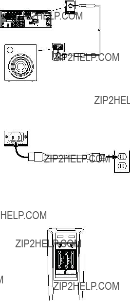
Connect the 12V Trigger Output
If your system has equipment that can be controlled by a DC trigger signal, connect it to the AVR???s 12V Trigger connector with a mono
Connect to AC Power
Connect the AC power cord to the AVR???s AC Input connector and then to a working AC power outlet.
AVR AC
Input Connector
AC Power
Outlet
Power Cord
(supplied)
Set Up the Remote Control
Install the Batteries in the Remote Control
Remove the remote control???s battery cover, insert the three supplied AAA batteries as shown in the illustration, and replace the battery cover.
NOTE: Remove the protective plastic from the AVR???s front panel to keep it from reducing the remote control???s effectiveness.
Program the Remote to Control Your Source Devices and TV
In addition to using the remote to control the AVR itself and the AM/FM radio, you can program the remote to control up to nine additional audio/video source devices plus your TV. The remote is also ready to operate your iPod or iPhone device when the device is docked in a connected The Bridge IIIP (not included).
Once you have programmed the remote, you can switch the remote???s control mode to access the functions for a particular source device by pressing the remote???s Source Selector button for that device. To control the AVR, press the remote???s AVR button.
Before you begin programming the remote, review the connections you ???lled in on the Input Connections and Source Buttons table on page 13. The Source Selector buttons are assigned to the components that you listed in the table???s ???Source Device Connected??? column.
1.Turn on the source device you want to program the remote to control.
2.Look up the code numbers for the device in Tables A11 ??? A17 in the Appendix. Write all the applicable code numbers in a convenient place.
3.Press and hold the Source Selector button for that source device until the Program Indicator LED on the remote starts to ???ash, then release it. (This procedure places the remote in the Programming mode.)
NOTE: If you???re programming one of the four HDMI source buttons, after pressing the HDMI button you must also press the Source Selector button for the type of device that will be controlled:
???Press DVD to control a DVD player.
???Press VID1 to control a VCR, DVR or Harman Kardon digital media center.
???Press VID2 to control a cable or satellite
4.Aim the remote at the source device and use the remote???s Number buttons to enter a code number from Step 2, above.
a)If the device turns off, press the Source Selector button again to save its code. The Source Selector button will ???ash, and the remote will exit the Programming mode.
b)If the device does not turn off, enter another code number.
c)If you run out of code numbers for a device, you can search through all of the codes in the remote???s library for devices of its type by pressing the Up or Down button repeatedly until the device turns off. When it does, press the Source Selector button to save the code.
5.Check that other functions control the device correctly. Sometimes manufacturers use the same Power code for several models, while other function codes vary. Repeat this process until you???ve programmed a satisfactory code set that operates most of the device???s functions.
6.If you searched through the remote???s code library to ???nd the code, you can ???nd out which code number you have programmed by pressing and holding the Source Selector button to
Repeat Steps 3 ??? 6 for each source device you want to control with the AVR remote.
In general, the label for each button on the remote describes the button???s function when used to control the AVR. However, the button may perform a very different function when used to control another device. Refer to the Remote Control Function List, Table A10 in the Appendix, for each button???s functions with the various product types.
You can also program the remote to perform Macros (preprogrammed code sequences that execute many code commands with a single button press) and
16

AVR 1650/AVR 165
Set Up the AVR
Set Up the AVR
Turn On the AVR
1.Set the
2.Press the
Unless you will not be using the AVR for an extended period of time, leave the Main Power switch set to ???On.??? When the Main Power switch is turned off, any settings you have programmed will be preserved for up to four weeks.
IMPORTANT NOTE: If the PROTECT message ever appears in the Message display, turn off the AVR and unplug it. Check all speaker wires for a short circuit (???+??? and
Using the
Although it???s possible to con???gure the AVR using only the remote and the
To access the menu system, press the OSD button on the remote. The Master menu will appear.
** MASTER MENU **
INPUT SETUP
SURROUND MODE
EzSet/EQ
MANUAL SETUP
SYSTEM SETUP
The Master menu consists of ???ve submenus: Input Setup, Surround Mode, EzSet/EQ, Manual Setup and System Setup.
Use the Up/Down/Left/Right buttons on the remote to navigate the menu system, and press the OK button to select a menu or setting line, or to enter a new setting.
The current menu, setting line or setting will appear in the
To return to the previous menu, navigate to the ???Back to Master Menu??? line and press the OK button. To exit the menu system, press the OSD button.
Most users should follow the instructions in this Set Up the AVR section to con???gure a basic home theater system. You may return to these menus at any time to make additional adjustments, such as those described in the Advanced Functions section, on pages 20 through 24.
Before you begin initial setup, all loudspeakers, a video display and all source devices should be connected to the AVR. You should be able to turn on the AVR and view the Master menu when you press the OSD button. If necessary, reread the Making Connections section and the beginning of this section before continuing.
Configure the AVR for Your Speakers
NOTE: If there are fewer than ???ve main speakers in your system, do not use the EzSet/EQ process. Instead, proceed as described in Manual Speaker Setup, on page 21.
1. Plug the supplied EzSet/EQ microphone into the AVR???s Headphone connector.
AVR
Headphone
Connector
EzSet/EQ Microphone
(supplied)
2.Place the microphone at ear height in your listening position. The microphone features a threaded insert on the bottom for mounting on a camera tripod.
3.Set the volume control on your subwoofer to approximately the halfway point.
4.Turn on your TV and select the TV input where you connected the AVR in Connect Your TV or Video Display, on page 13.
5.Press the remote control???s OSD button. The AVR???s
**MASTER MENU **
INPUT SETUP
SURROUND MODE
EzSet/EQ
MANUAL SETUP
SYSTEM SETUP
6.Use the remote???s arrow and OK buttons to select ???EzSet/EQ.???
* EzSet/EQ *
Place Microphone at listening position and plug into Headphone Jack
Do you want to start
EzSet/EQ?
YES NO
7.Select ???YES.??? The Speaker Con???guration menu will appear.
8.Select ???5.1.???
9.The test will begin. Make sure that the room is quiet while the test noise is playing through the speakers.
10.When the test ???nishes, select ???View Settings??? to see the results of the EzSet/EQ process, or select ???Done??? to exit.
17

AVR 1650/AVR 165
Set Up the AVR, continued
Assign the Digital Audio Connectors
1.Review the input connections you listed on the Input Connections and Source Buttons table, on page 13. Note which source devices you connected to the digital audio connectors. (If you did not connect any source devices to the digital audio connectors, you can skip this section.)
2.Turn on your TV and select the TV input where you connected the AVR in Connect Your TV or Video Display, on page 13.
3.Press the remote control???s OSD button. The AVR???s
**MASTER MENU **
INPUT SETUP
SURROUND SELECT
SPEAKER SETUP
SYSTEM SETUP
4.Use the remote???s arrow and OK buttons to select ???Input Setup.??? The Input Setup menu will appear.
* INPUT SETUP *
BACK TO MASTER MENU
5.For each source device you connected to a digital audio input:
a)Use the remote???s Up and Down arrow buttons to select ???Source.??? Use the Left and Right arrow buttons to change the listed source to one of the sources you connected to a digital audio input connector.
b)Use the remote???s down arrow button to select ???Audio In.???
* INPUT SETUP *
BACK TO MASTER MENU
c) Use the remote???s Left and Right arrow buttons to select the digital audio input where you connected the source device.
Additional Input Setup Menu Items
You can also adjust the following settings independently for each source:
Title: You may change the display name for any source (except the radio). This feature may help you to select the correct source device even when you have forgotten which physical connections you used.
1.Move the cursor to the Title line and press the OK button. A block cursor will blink.
2.Use the Up/Down buttons to scroll through the alphabet in upper and lower case, the numbers and many punctuation marks. When you have selected the desired character, press the Right button to move to the next space. Press the Right button twice to leave a blank space.
3.Press the OK button when you have ???nished.
Auto Poll: The Auto Poll feature is used when both an analog audio and a digital audio connection have been made for one source device. If no digital signal is available, the AVR will automatically switch to the analog input for the source. This situation can occur with some cable or satellite television broadcasts, where some channels are broadcast with digital audio and others with analog audio, or when a DVD player is paused or stopped.
For some sources such as DVD players, the Auto Poll feature is unnecessary and may be undesirable. To turn Auto Poll off, move the cursor to the Auto Poll line and press the Left/ Right buttons until Off appears. With Auto Poll turned off, the AVR will check for a signal only at the audio input assigned to the source.
The remaining Input Setup menu items adjust the AVR???s audio performance for that source and may be skipped at this time. For most listening, we recommend leaving these settings at their factory defaults, allowing you to enjoy the sound mix created by your favorite movie and music artists.
BXR: Enhances bass performance when playing MP3 tracks. Select On, or leave it at the default Off setting for
Tone: This setting determines whether the treble and bass controls are active. When this line is set to Off, the tone controls are out of the circuit, with no changes to the sound. When this line is set to On, the bass and treble frequencies are boosted or cut, depending upon the Bass and Treble settings (see below).
Bass and Treble: Boost or cut the low or high frequencies by up to 10dB by using the Left/Right buttons to change the setting by 2dB at a time.
When you???re ???nished, press the remote???s OSD button to turn off the
18

AVR 1650/AVR 165
Operating Your AVR
Operating Your AVR
Now that you have installed your components and completed a basic con???guration, you are ready to begin enjoying your home theater system.
Controlling the Volume
Adjust the volume either by turning the
0dB is the maximum recommended volume for your AVR. Although it???s possible to turn the volume to a higher level, doing so may damage your hearing and your speakers. For certain more dynamic audio materials, even 0dB may be too high, allowing for damage to equipment. Use caution with regard to volume levels.
Muting the Sound
To mute all speakers and the headphones, press the Mute button on the remote. Any recording in progress will not be affected. The MUTE message will appear in the front- panel display as a reminder. To restore the sound, press the Mute button again, or adjust the volume.
Listening Through Headphones
Plug the
Selecting a Source
There are two different ways to select a source:
???Press the
???Directly select any source by pressing its Source Selector button on the remote.
The AVR selects the audio and video inputs assigned to the source and any other settings you made during setup.
The source name, the audio and video inputs assigned to the source, and the surround mode will appear on the front panel.
Video Troubleshooting Tips
If there is no picture:
???Check the source selection.
???Check all connections for a loose or incorrect connection.
???Check the
Additional Tips for Troubleshooting HDMI Connections
???Turn off all devices (including the TV, the AVR and any source components).
???Unplug the HDMI cables, starting with the cable between the AVR and the TV, and continuing with the cables between the AVR and each source device.
???Carefully reconnect the cables from the source devices to the AVR. Connect the cable from the AVR to the TV last.
???Turn on the devices in this order: TV, AVR, source devices.
NOTE: Depending upon the particular components involved, the complexity of the required communication between HDMI components may cause delays of up to a minute in the completion of some actions, such as input switching or switching between SD and HD channels.
Listening to FM and AM Radio
Select the AM/FM source. Use the Tuning Up/Down buttons to tune a station, which will be shown on the
The AVR defaults to automatic tuning, meaning each press of the Tuning Up/Down buttons scans until a station with acceptable signal strength is found. To switch to manual tuning, in which each press of a Tuning button steps through a single frequency increment, press the Tuning Mode button. Each press of the Tuning Mode button toggles between the automatic and manual tuning modes.
Once you have tuned an FM station, toggling the Tuning Mode setting also switches the radio between stereo and monaural reception. (Mono reception may improve reception of weaker stations.)
Preset Stations
A total of 30 stations (AM and FM combined) may be stored as presets. When the desired station has been tuned in, press the Memory button on the remote, and two dashes will ???ash on the
To tune a preset station, press the Preset Up/Down buttons or enter the preset number using the Number buttons.
Listening to an iPod/iPhone Device
When The Bridge IIIP is connected to its proprietary input on the AVR, and an iPod or iPhone is docked, you may play the audio materials on your iPod or iPhone through your
As of this writing, your AVR supports audio playback from the following Apple products: iPod classic, iPod nano 3G, iPod nano 4G, iPod nano 5G, iPod nano 6G, iPod touch, iPod touch 2G, iPod touch 3G, iPod touch 4G, iPhone, iPhone 3G, iPhone 3GS, iPhone 4G. For the latest compatibility information, please see our Web site: www.harmankardon.com.
After docking an iPod or iPhone device in The Bridge IIIP, select the Bridge Source Selector button on the remote. ???Bridge??? will appear on the
SONG: Previously Disenchanted
ARTIST: Jugalbandi
ALBUM: Yellow Star Mailing List
10:17  15:33
15:33
The screen will show the currently playing song, artist, album, elapsed time, play mode and total track time. Use the remote???s Transport Control buttons to control playback.
Navigating iPod/iPhone Device Menus
Pressing the remote???s Speaker Setup (Menu) button while an iPod/iPhone device is playing in The Bridge IIIP will display the iPod/iPhone Menu screen on a connected TV:
Menu
Playlists
Artists
Albums
Songs
Podcasts
Genres
Composers
Audiobooks
Use the Up/Down and OK buttons to navigate through the list and select the desired category. When the category???s screen appears, use the Up/Down and OK buttons to navigate within the category and make selections. NOTE: Not all categories may appear with all iPod/iPhone devices.
???To return to a previous menu screen at any time, press the Speaker Setup (Menu) button.
19

AVR 1650/AVR 165
Selecting a Surround Mode
Selecting a surround mode can be as simple or sophisticated as your individual system and tastes. Feel free to experiment, and you may ???nd a few favorites for certain sources or program types. You can ???nd more detailed information on surround modes in Audio Processing and Surround Sound, on this page.
To select a surround mode, press the OSD Button on the remote to display the Master menu:
** MASTER MENU **
INPUT SETUP
SURROUND MODE
EzSet/EQ
MANUAL SETUP
SYSTEM SETUP
Use the Up/Down and OK buttons to select Surround Mode. The Surround Mode menu will appear:
* MODE : MUSIC *
DOLBY PLII MUSIC
 CENTER WIDTH :3
DIMENSION :0
PANORAMA :Off
BACK TO MASTER MENU
Use the Up/Down and OK buttons to select the desired
Auto Select: For a digital program, such as a movie recorded with a Dolby Digital or DTS soundtrack, the AVR will automatically use the soundtrack???s native surround format. For
Virtual Surround: When only two main speakers are present in the system, you can use HARMAN virtual surround to create an enhanced sound ???eld that virtualizes the missing speakers.
Stereo: When you want
??????2 CH Stereo??? uses two speakers.
??????5 CH Stereo??? plays the
Movie: Select from the following when you want a surround mode for movie playback: Logic 7 Movie or Dolby Pro Logic II Movie.
Music: Select from the following when you want a surround mode for music playback: Logic 7 Music or Dolby Pro Logic II Music. The Dolby Pro Logic II Music mode provides some additional settings. See Audio Processing and Surround Sound, on page 20, for more information.
Video Game: Select from the following when you want a surround mode for game
playback: Logic 7 Game or Dolby Pro Logic II Game.
After you select the
* MODE : MUSIC *
DOLBY PLII MUSIC
 CENTER WIDTH :3
DIMENSION :0
PANORAMA :Off
BACK TO MASTER MENU
Operating Your AVR, continued, and Advanced Functions
Use the Left/Right buttons to change the surround mode.
You can also select surround modes using the AVR???s
1.Press the Surr Mode button. The Message display will show the
2.To change the surround mode within the
3.To change the
Advanced Functions
Much of the adjusting and con???guration your AVR requires is handled automatically, with little intervention required on your part. You can also customize your AVR to suit your system and your tastes. In this section, we will describe some of the more advanced adjustments available to you.
Audio Processing and Surround Sound
Audio signals can be encoded in a variety of formats that can affect not only the quality of the sound but also the number of speaker channels and the surround mode. You may also manually select a different surround mode, when available.
Analog Audio Signals
Analog audio signals usually consist of two channels ??? left and right. Your AVR offers two options for analog playback:
DSP Surround Off Mode: The DSP Surround Off mode digitizes the incoming signal and applies the
Analog Surround Modes: Your AVR is able to process
Digital Audio Signals
Digital audio signals offer greater ???exibility and capacity than analog signals and allow the encoding of discrete channel information directly into the signal. The result is improved sound quality and startling directionality, since each channel???s information is transmitted discretely.
Surround Modes
When in doubt, check the jacket of your disc for more information on which surround modes are available. Usually, nonessential sections of the disc, such as trailers, extra materials or the disc menu, are available only in Dolby Digital 2.0
The channels included in a typical
Digital formats include Dolby Digital 2.0 (two channels only), Dolby Digital 5.1, Dolby Digital EX (6.1), Dolby Digital Plus (7.1), Dolby TrueHD (7.1),
20
AVR 1650/AVR 165
Advanced Functions, continued
Audio (7.1),
When the AVR receives a digital bitstream, it detects the encoding method and the number of channels, which is displayed brie???y as three numbers, separated by slashes (e.g., ???3/2/.1???).
The ???rst number indicates the number of front channels in the signal: ???1??? represents a monophonic recording (usually an older program that has been digitally remastered or, more rarely, a modern program for which the director has chosen mono as a special effect). ???2??? indicates the presence of the left and right channels but no center channel. ???3??? indicates that all three front channels (left, right and center) are present.
The second number indicates whether any surround channels are present: ???0??? indicates that no surround information is present. ???1??? indicates that a matrixed surround signal is present. ???2??? indicates discrete surround left and right channels. (Bitstreams with discrete surround back left and right channel signals will be indicated by a ???4,??? although the AVR downmixes the surround
The third number is used for the LFE channel: ???0??? indicates no LFE channel. ???.1??? indicates that an LFE channel is present.
Dolby Digital 2.0 signals may include a Dolby Surround ???ag indicating
When a PCM signal is received, the PCM message and the sampling rate (32kHz, 44.1kHz, 48kHz or 96kHz) will appear.
When only two channels ??? left and right ??? are present, the analog surround modes may be used to decode the signal into multiple channels. If you would prefer a different surround format than the native signal???s digital encoding, press the Surround Modes button to display the Surround Modes menu (see Selecting a Surround Mode, on page 20).
The Auto Select option sets the surround mode to the native signal???s digital encoding, e.g., Dolby Digital, DTS, Dolby TrueHD or
Each
???Virtual Surround: HARMAN virtual speaker.
???Stereo:
???Movie: Logic 7 Movie.
???Music: Logic 7 Music.
???Video Game: Logic 7 Game.
You may select a different mode for each category. Below is a complete list of available surround modes. (The actual surround modes available will depend on the number of speakers in your system.)
???Virtual Surround: HARMAN virtual speaker.
???Stereo:
???Movie: Logic 7 Movie, Dolby Pro Logic II Movie.
???Music: Logic 7 Music, Dolby Pro Logic II Music.
???Video Game: Logic 7 Game, Dolby Pro Logic II Game.
Once you have programmed the surround mode for each type of audio, select the line from the Surround Modes menu to override the AVR???s automatic
Please refer to Table A9 in the Appendix for more information on which surround modes are available with different bitstreams.
Dolby Pro Logic II Music Mode Adjustments
When you select Dolby Pro Logic II as the music surround mode, additional adjustments become available:
* MODE : MUSIC *
DOLBY PLII MUSIC
 CENTER WIDTH :3
DIMENSION :0
PANORAMA :Off
BACK TO MASTER MENU
Center Width: This setting affects how vocals sound through the three front speakers. A lower number focuses the vocal information tightly on the center channel. Higher numbers (up to 7) broaden the vocal soundstage. Use the Left/Right buttons to adjust this setting.
Dimension: This setting affects the depth of the surround presentation, allowing you to ???move??? the sound toward the front or rear of the room. The setting of ???0??? is a neutral default. Setting
Panorama: With the Panorama mode turned on, some of the sound from the front speakers is moved to the surround speakers, creating an enveloping ???wraparound??? effect. Each press of the OK button toggles the setting On or Off.
Manual Speaker Setup
Your AVR is ???exible and may be con???gured to work with most speakers and to compensate for the acoustic characteristics of your room.
The EzSet/EQ process automatically detects the capabilities of each connected speaker and optimizes the AVR???s performance with your speakers. If you are unable to run EzSet/ EQ calibration, or if you wish to set up your AVR for your speakers manually, use the Manual Speaker Setup
Before beginning, place your loudspeakers as explained in the Place Your Speakers section, on page 10, and connect them to the AVR. Consult the owner???s guide for the speakers or the manufacturer???s Web site for their
Record your con???guration settings in Tables A4 and A6 in the Appendix for easy
Step One ??? Determine Your Speakers??? Crossover Frequencies
Without using the EzSet/EQ process, the AVR can???t detect how many speakers you???ve connected to it; nor can it determine their capabilities. Consult the technical speci???cations for all of your speakers and locate the frequency response, usually given as a range, e.g., 100Hz ??? 20kHz (??3dB). Write down the lowest frequency that each of your speakers is capable of playing (100Hz in the above example) as the crossover in Table A6 in the Appendix. NOTE: This frequency is not the same as the crossover frequency listed in the speaker???s speci???cations.
For the subwoofer, write down the transducer size. The AVR???s bass management determines which speakers will be used to play back the
With proper bass management, the AVR divides the source signal at a crossover point. All information above that crossover point is played through your system???s speakers, and all information below the crossover point is played through the subwoofer. This way, each loudspeaker in your system will perform at its best, delivering a more powerful and enjoyable sound experience.
21

AVR 1650/AVR 165
Advanced Functions, continued
Step Two ??? Measure the Speaker Distances
Ideally, all of your speakers would be placed in a circle, with the listening position at the center. However, you may have had to place some speakers a little farther away from the listening position than others. Sounds that are supposed to arrive simultaneously from different speakers may blur, due to different arrival times.
Your AVR provides a Distance adjustment that compensates for these
Measure the distance from each speaker to the listening position, and write it down in Table A4 in the Appendix. Even if all of your speakers are the same distance from the listening position, enter your speaker distances as described in Set the Speaker Distances, on this page.
Step Three ??? Manual Setup Menu
Now you are ready to program the AVR. Sit in your usual listening position, and make the room as quiet as possible.
With the AVR and video display turned on, press the OSD button to display the menu system and select Manual Setup. The Manual Setup menu will appear:
* MANUAL SETUP *
NUMBER OF SPEAKERS
SUB MODE : SUB
CROSSOVER
DISTANCE
LEVEL ADJUST
BACK TO MASTER MENU
NOTE: All of the speaker setup submenus include a ???Back to?????? option. To save the current settings, select the Back to??? option.
For best results, adjust the submenus in this order: Number of Speakers, Crossover, Sub Mode, Distance and Level Adjust.
Number of Speakers
This selection lets you program the correct setting for each speaker group. The settings in this menu affect the remainder of the
Select ON when the speakers are present in the system; select OFF for positions where no speakers are installed. The Front Left & Right setting is always ON and may not be disabled.
* NUMBER OF SPEAKERS *
BACK TO MANUAL SETUP
When you have ???nished, select Back to Manual Setup.
Crossover (Size)
After you return to the Manual Setup menu, navigate to the Crossover line and press the OK button to display the Crossover menu.
* CROSSOVER *
BACK TO MANUAL SETUP
Refer to Table A6 for each speaker???s crossover frequency.
NOTE: The AVR will let you adjust settings only for those speaker groups you set to On in the Number of Speakers menu.
For each speaker group, select one of these eight crossover frequencies: LARGE, 40Hz, 60Hz, 80Hz, 100Hz, 120Hz, 150Hz or 200Hz. If the speaker???s crossover frequency is below 40Hz, select the ???rst option, LARGE. This setting doesn???t refer to the speaker???s physical size but to its frequency response, which is also called ???full range.???
Specify the size of the subwoofer???s transducer as 8, 10, 12 or 15 inches. The AVR always sets the subwoofer crossover to 100Hz but uses the transducer size for equalization.
Write down the settings in Table A6 in the Appendix.
When you have ???nished entering the settings, select Back To Manual Setup.
Sub Mode
After you return to the Manual Setup menu, navigate to the Sub Mode line and press the OK button to display the Sub Mode menu. This setting depends upon the Crossover setting you selected for the front left and right speakers.
???If you set the front speakers to a numeric crossover frequency, the subwoofer setting will always be SUB. All
???If you set the front speakers to LARGE, select one of the three following settings for the subwoofer:
L/R+LFE: This setting sends all
OFF: Select this setting when no subwoofer is in use. All
LFE: This setting plays
When you have ???nished entering the settings, select Back To Manual Setup.
Set the Speaker Distances
As described above in Step Two, when you measured the distances from each of your speakers to the listening position, your AVR provides an adjustment that compensates for the different distances so that the sound from each speaker will reach the listening position at the proper time. This process will improve the clarity and detail of the sound.
After you return to the Manual Setup menu, navigate to the Distance line and press the OK button to display the Distance menu.
DELAY RESET : OFF
UNIT : FEET
A/V SYNC DELAY : 0mS
BACK TO MANUAL SETUP
Enter the distance from each speaker to the listening position that you measured in Step Two and recorded in Table A4 in the Appendix (see page 28). Select a speaker, then use the Left/Right buttons to change the measurement. You can enter distances between 0 and 30 feet (9.1m). The default distance for all speakers is 10 feet (3m).
The default unit of measurement is feet. To change the unit to meters, scroll down to the Unit line and press the Left/Right buttons.
When you have ???nished entering the settings, select Back To Manual Setup.
22

AVR 1650/AVR 165
Advanced Functions, continued
Step Four ??? Setting Channel Output Levels Manually
For a conventional stereo AVR, a simple balance control adjusts the stereo imaging by varying the relative loudness of the left and right channels. In a home theater system with up to seven main channels plus a subwoofer, achieving proper imaging becomes both more critical and more complex. The goal is to ensure that each channel is heard at the listening position with equal loudness (when signals of equal loudness are played through them).
Your AVR???s EzSet/EQ calibration can handle this critical task for you simply and automatically. However, the AVR???s Adjust Speaker Levels menu allows you to calibrate the levels manually, either using the system???s
After you return to the Manual Setup menu, navigate to the Level Adjust line and press the OK button to display the Level Adjust menu.
* LEVEL ADJUST*
BACK TO MANUAL SETUP
All of the system???s speakers will appear with their current level settings. You can adjust each speaker???s level between
While making adjustments, you can measure the channel levels in one of these ways:
???Preferably, use a handheld SPL meter set to the
???By ear. Adjust the levels so that the test tone sounds equally loud to you when it plays through each speaker.
To set your levels using the AVR???s internal test tone, select the menu???s Test Tone Seq line and use the Left/Right buttons to select between Auto and Manual. After selecting Auto or Manual, move the cursor to the Test Tone line and use the Left/Right buttons to change the setting to On.
Auto: The test tone will automatically circulate to all speakers, as indicated by the highlight bar. Use the Left/Right buttons to adjust the level for any speaker when the test tone is paused there. Use the Up/Down buttons to move the cursor to another line, and the test tone will follow the cursor. To stop the test tone, use the Up/Down buttons to move the cursor out of the screen???s
Manual: The test tone will stay on the current speaker until you use the Up/Down buttons to move it to another speaker. Use the Left/Right buttons to adjust the level for the speaker through which the test tone is playing.
If you are using an external source to set your output levels, set Test Tone to Off, use the Up/Down buttons to navigate to each speaker, and use the Left/Right buttons to adjust the speaker???s level while the source plays. NOTE: If you are using a handheld SPL meter with external source material, such as a test disc or an audio selection, play it and adjust the AVR???s master volume control until the meter measures 75dB. Then adjust the individual speaker levels.
Channel Reset: To reset all channel levels to their factory defaults of 0dB, select this line and press the Left/Right buttons.
When you have ???nished adjusting the speaker levels, record the settings in Table A6 in the Appendix. Then select the Back to Manual Setup option in the OSD.
Notes on Setting Speaker Volumes in Home Theater Systems:
While setting your system???s individual speaker volume levels is ultimately up to your personal taste, here are some ideas you may ???nd helpful:
???For ???lms and
???For multichannel music recordings, some music producers will create a sound ???eld that places the musicians all around you; others will create a sound ???eld that places the musicians in front of you, with more subtle ambience in the surround speakers (as you would experience in a concert hall).
???In most
Notes on Setting Subwoofer Volume:
???Sometimes the ideal subwoofer volume setting for music is too loud for ???lms, while the ideal setting for ???lms is too quiet for music. When setting the subwoofer volume, listen to both music and ???lms with strong bass content and ???nd a ???middle ground??? volume level that works for both.
???If your subwoofer always seems too loud or too quiet, you may want to place it in a different location. Placing the subwoofer in a corner will always tend to increase its bass output, while placing it away from any walls or corners will always tend to lessen its bass output.
System Setup
The AVR???s System Setup menu lets you customize in what way many of the AVR???s features operate. Press the OSD button and navigate to the System Setup line. Press the OK button to display the System Setup menu.
VFD Fade Time Out: Some people ???nd the brightness of the AVR???s
Volume Default and Default Volume Set: These two settings are used together to program the volume level when you turn on the AVR. Set Volume Default to On, and then set the Default Volume Set to the desired
HDMI Audio To TV: This setting determines whether HDMI audio signals are passed through the HDMI Monitor Out connector to the video display. In normal operation, leave this setting at Off, as audio will be played through the AVR. To use the TV by itself, without the home theater system, turn this setting to On. In this case, you will need to mute the TV???s speakers (or switch the setting to Off) when using the AVR for audio.
Semi OSD Time Out: Program the amount of time (2 to 5 seconds) the
Full OSD Time Out: Program the amount of time (20, 30, 40 or 50 seconds) the full OSD
menus remain visible on screen. The full OSD system may not be deactivated. NOTE: It isn???t possible to view video sources while the full OSD menus are displayed.
HDMI Link: This setting allows the communication of control information among the HDMI devices in your system. Turn this setting to On to allow control communication among the HDMI devices; turn the setting to Off to forbid control communication.
HDMI ARC: Selecting On will send audio from the TV to the AVR via the HDMI Audio Return Channel (ARC) connection (which is in the HDMI cable connecting the AVR to the TV). This way, whenever you???re watching a source that is connected directly to your TV (such as an Internet connection), you can listen to the sound through the AVR. NOTE: This setting is available only when HDMI Link is set to On.
23
AVR 1650/AVR 165
Advanced Functions, continued
Advanced Remote Control Programming
Remote
The
To program
1.For three seconds, press and hold the Source Selector button (or the AVR button) for the main device the remote will be operating. The Program Indicator LED will ???ash, indicating that the remote is in Program mode and that you may release the button.
2.Select the type of
a)To program
b)To program
c)To program
3.Press the Source Selector button for the device whose volume, channel or transport- controls you will use while operating the device selected in the ???rst step. The Program Indicator LED will ???ash to con???rm.
To undo
You may reassign the
Programming Macro Commands
Each of the AVR remote???s four Macro buttons and the Power On button (see System Remote Control Functions, on pages 8 and 9) can be programmed to send out up to 19 commands at one time from a single button push. Any AVR remote control button???s function from any mode (except the Mute button, the Dim button and the Channel Up/ Down buttons) can be programmed into a macro.
NOTE: Use caution when programming complicated macros. It isn???t possible to program a pause or delay before sending additional commands after a ???Power On??? command, and the component may not be ready to respond to commands immediately after powering on.
To program a macro:
1.Simultaneously press one of the four Macro buttons, or the Power On button, and the Mute button to enter the Programming mode.
2.Press in up to 19 commands that you want stored in that Macro button. Press the Source Selector button for each device (or AVR button for the AVR itself) before you enter individual commands. This step counts as one of the 19 commands allowed for each Macro.
3.For the Power On command, DO NOT press the Power On button. Press the Mute button instead.
4.Press the Power Off button to program the Power Off command.
5.Press the Sleep button to end the programming process.
It isn???t possible to ???edit??? a command within a macro. However, you may erase the macro as follows:
1.Simultaneously press and hold the Mute button and the Macro button containing the macro until the Program Indicator LED ???ashes.
2.Press the Channel Down button to erase the macro.
To execute a macro, press the Macro button (or the Power On button) into which you programmed the macro.
Recording
NOTES:
1.The AVR does not convert analog signals to digital or vice versa.
2.Only PCM digital audio signals are available for recording. Proprietary formats such as the Dolby Digital and DTS bitstreams may not be recorded using the digital audio connections. Use the analog audio connections to make an analog recording.
3.HDMI and component video sources are not available for recording.
4.Please make certain that you are aware of any copyright restrictions on any material you record. Unauthorized duplication of copyrighted materials is prohibited by law.
Sleep Timer
The sleep timer sets the AVR to play for up to 90 minutes and then turn off automatically.
Press the Sleep button on the remote, and the time until
When the sleep timer has been set, the
If you press the Sleep button after the timer has been set, the remaining play time will be displayed. Press the Sleep button again to change the play time.
Resetting the Remote
To reset the remote to its
Processor Reset
If the AVR behaves erratically after a power surge, ???rst turn off the
NOTE: A processor reset erases all user con???gurations, including video resolution, speaker and level settings, and tuner presets. After a reset, reenter all of these settings from your notes in the Appendix worksheets.
To reset the AVR???s processor:
1.Press the
2.Press and hold the
If the AVR does not function correctly after a processor reset, contact an authorized Harman Kardon service center for assistance. Authorized service centers may be located by visiting our Web site at www.harmankardon.com.
Memory
If the AVR is unplugged or experiences a power outage, it will retain your user settings for up to four weeks.
24
AVR 1650/AVR 165
Troubleshooting
Troubleshooting
Additional information on troubleshooting possible problems with your AVR and
25

AVR 1650/AVR 165
Specifications
Specifications
Audio Section
FM Tuner Section
AM Tuner Section
Video Section
General Specifications
26
AVR 1650/AVR 165
Appendix
Appendix ??? Default settings, worksheets, remote product codes
Table A1 ??? Recommended Source Component Connections
Note: The AVR is equipped with a total of three digital audio inputs. Certain digital audio connections are recommended simply because those digital audio inputs are assigned to those sources by default at the factory. But any digital audio input may be reassigned to any source. Since you may not be using all of the AVR's sources, you may reassign a digital audio input that is recommended for a source you aren???t using to another device. Table A1 is a guideline; you may need to make adjustments to fit your system.
Table A2 ??? Source Setting Defaults
27

AVR 1650/AVR 165
Appendix
Table A3 ??? Speaker/Channel Setting Defaults
Table A4 ??? Distance Settings
Front Left
Center
Front Right
Surround Right
Surround Left
Surround Back Right
Surround Back Left
Subwoofer
28

AVR 1650/AVR 165
Appendix
Table A5 ??? Source Settings
Table A6 ??? Speaker/Channel Settings
Crossover
Distance
Channel Level Adjust
29
AVR 1650/AVR 165
Appendix
Table A7 ??? Remote Control Codes
Table A8 ??? System Settings
30
AVR 1650/AVR 165
Appendix
Table A9 ??? Surround Modes
31
AVR 1650/AVR 165
Appendix
Table A9 ??? Surround Modes (cont.)
32

AVR 1650/AVR 165
Appendix
Refer to the numbered buttons when using the Function ListRemote Control
33
AVR 1650/AVR 165
Appendix
Table A10 ??? Remote Control Function List
34
AVR 1650/AVR 165
Appendix
Table A10 ??? Remote Control Function List (cont.)
Note: When any of the transport controls are pressed while the remote is in AVR or Video 2 mode, the remote will automatically switch to DVD mode, and the command will be applied to the DVD player. If you then press a button native to the original mode, e.g., Volume Down for the AVR, the remote will revert to the original mode. See
35
AVR 1650/AVR 165
Appendix
Table A11 ??? Remote Control Product Codes: TV
36
AVR 1650/AVR 165
Appendix
Table A11 ??? Remote Control Product Codes: TV (cont.)
Table A12 ??? Remote Control Product Codes: VCR
37
AVR 1650/AVR 165
Appendix
Table A13 ??? Remote Control Product Codes: CD
38
AVR 1650/AVR 165
Appendix
Table A14 ??? Remote Control Product Codes: DVD
Table A15 ??? Remote Control Product Codes: SAT
39
AVR 1650/AVR 165
Appendix
Table A15 ??? Remote Control Product Codes: SAT (cont.)
Table A16 ??? Remote Control Product Codes: Tape
Table A17 ??? Remote Control Product Codes: Cable
40
AVR 1650/AVR 165
Appendix
Table A17 ??? Remote Control Product Codes: Cable (cont.)
41

HARMAN Consumer, Inc.
8500 Balboa Boulevard, Northridge, CA 91329 USA
?? 2011 HARMAN International Industries, Incorporated. All rights reserved.
Harman Kardon and Logic 7 are trademarks of HARMAN International Industries, Incorporated, registered in the United States and/or other countries. EzSet/EQ is a trademark of HARMAN International Industries, Incorporated.
Apple, iPhone, iPod, iPod touch, iPod nano and iPod classic are trademarks of Apple Inc., registered in the U.S. and other countries.
CEA is a registered trademark of the Consumer Electronics Association.
Manufactured under license from Dolby Laboratories. Dolby, the
Laboratories. MLP Lossless is a trademark of Dolby Laboratories.
Manufactured under license under U.S. Patent #???s 5,451,942; 5,956,674; 5,974,380; 5,978,762; 6,226,616; 6,487,535; 7,003,467 and other U.S. and worldwide patents issued and pending. DTS is a registered trademark, and DTS 96/24,
HDMI, the HDMI logo and
TiVo is a registered trademark of TiVo Inc.