Designed to Entertain.TM
AVR 145
AUDIO/VIDEO RECEIVER
OWNER???S MANUAL
Designed to Entertain.TM
AVR 145
AUDIO/VIDEO RECEIVER
OWNER???S MANUAL

TABLE OF CONTENTS
3 SAFETY INFORMATION
5 INTRODUCTION
7
9
11 REMOTE CONTROL FUNCTIONS
14INTRODUCTION TO HOME THEATER
15CONNECTIONS
15 Speaker Connections
15 Subwoofer
15Connecting Source Devices to the AVR
16Audio Connections
16Video Connections
17Antennas
17
18SPEAKER PLACEMENT
19INSTALLATION
19 Step One ??? Connect the Speakers
19 Step Two ??? Connect the Subwoofer
19 Step Three ??? Connect the Antennas
19 Step Four ??? Connect the Source Components
22Step Five ??? Connect Video Display
22Step Six ??? Plug in AC Power
22Step Seven ??? Insert Batteries in Remote
23Step Eight ??? Program Sources Into the Remote
24Step Nine ??? Turn On the AVR 145
25INITIAL SETUP
25Using the
25Step One ??? Determine Speaker Size
26Step Two ??? Measure Speaker Distances
26Step Three ??? Manual Setup Menu
26Speaker Size Menu
27Speaker Crossover Menu
28Delay Adjust Menu
28Step Four ??? EzSet Output Level Calibration
29Step Five ??? Configure Sources
31 OPERATION
31Turning On the AVR 145
31Sleep Timer
31Volume Control
32Mute Function
32 Tone Controls
32 Headphones
32Source Selection
33Audio Input Selection
33Video Input Selection
33
33Using the Tuner
34Recording
34Using TheBridgeTM
35Selecting a Surround Mode
36ADVANCED FUNCTIONS
36Audio Processing and Surround Sound
36Digital Audio Signals
37Surround Modes
38Dolby Surround Settings
41Setting Channel Output Levels Manually
42System Settings
43Dim Function
43Macros
44Resetting the Remote
44Processor Reset
44Memory
45TROUBLESHOOTING GUIDE
46TECHNICAL SPECIFICATIONS
46Trademark Acknowledgements
47APPENDIX
WARNING
To prevent fire or shock hazard, do not expose this appli- ance to rain or moisture.
For Canadian model
This class B digital apparatus complies with Canadian
For models having a power cord with a polarized plug: CAUTION: To prevent electric shock, match wide blade of plug to wide slot, fully insert.
Mod??le pour les Canadien
Cet appareil num??rique de la classe B est conforme ?? la norme
Sur les mod??les dont la fiche est polarisee: ATTENTION: Pour ??viter les chocs ??lectriques, introduire la lame la plus large de la fiche dans la borne correspondante de la prise et pousser jusqu???au fond.
2

SAFETY INFORMATION
CAUTION
RISK OF ELECTRIC SHOCK
DO NOT OPEN
1.Read these instructions.
2.Keep these instructions.
3.Heed all warnings.
4.Follow all instructions.
5.Do not use this apparatus near water.
6.Clean only with a dry cloth.
7.Do not block any ventilation openings. Install in accordance with the manufacturer???s instructions.
8.Do not install near any heat sources such as radiators, heat registers, stoves or other appara- tus (including amplifiers) that produce heat.
9.Do not defeat the safety purpose of the polar- ized or
10.Protect the power cord from being walked on or pinched, particularly at plugs, convenience receptacles and the point where they exit from the apparatus.
11.Only use attachments/accessories specified by the manufacturer.
12.Use only with the cart, stand, tripod, bracket or table specified by the manufacturer or sold with the apparatus. When a cart is used, use caution when moving the cart/apparatus combi- nation to avoid injury from
13.Unplug this apparatus during lightning storms or when unused for long periods of
time.
14. Refer all servicing to qualified service personnel. Servicing is required when the apparatus has been
damaged in any way, such as
15.Do not use attachments not recommended by the product manufacturer, as they may cause hazards.
16.This product should be operated only from the type of power source indicated on the mark- ing label. If you are not sure of the type of power supply to your home, consult your product dealer or local power company. For products intended to operate from battery power, or other sources, refer to the operating instructions.
17.If an outside antenna or cable system is con- nected to the product, be sure the antenna or cable system is grounded so as to provide some protection against voltage surges and
18.An outside antenna system should not be located in the vicinity of overhead power lines or other electric light or power circuits, or where it can fall into such power lines or circuits. When installing an outside antenna system, extreme care should be taken to keep from touching such power lines or circuits, as contact with them might be fatal.
19.Do not overload wall outlets, extension cords, or integral convenience receptacles, as this can result in a risk of fire or electric shock.
20.Never push objects of any kind into this product through openings, as they may touch
Figure A.
Example of Antenna Grounding as per
National Electrical Code ANSI/NFPA 70
dangerous voltage points or
21.The apparatus shall not be exposed to drip- ping or splashing, and no objects filled with liq- uids, such as vases, shall be placed on the apparatus.
22.Do not attempt to service this product your- self, as opening or removing covers may expose you to dangerous voltage or other hazards. Refer all servicing to qualified service personnel.
23.When replacement parts are required, be sure the service technician has used replacement parts specified by the manufacturer or that have the same characteristics as the original part. Unauthorized substitutions may result in fire, elec- tric shock or other hazards.
24.Upon completion of any service or repairs to this product, ask the service technician to per- form safety checks to determine that the product is in proper operating condition.
25.The product should be mounted to a wall
or ceiling only as recommended by the manu- facturer.
3

SAFETY INFORMATION
Important Safety Information
Verify Line Voltage Before Use
Your AVR 145 has been designed for use with
If you have any questions about the voltage requirements for your specific model, or about the line voltage in your area, contact your selling dealer before plugging the unit into a wall outlet.
unit???s feet may leave marks on certain wood or veneer materials. Use caution when placing the unit on soft woods or other materials that may be damaged by heat or heavy objects. Some surface finishes may be particularly sensitive to absorbing such marks, due to a variety of factors beyond Harman Kardon's con- trol, including the nature of the finish, cleaning materials used, and normal heat and vibration caused by the use of the product, or other factors. We recommend that caution be exercised in choosing an installation location for the component and in normal maintenance practices, as your warranty will not cover this type of damage to furniture.
Do Not Use Extension Cords
To avoid safety hazards, use only the power cord attached to your unit. We do not recommend that extension cords be used with this product. As with all electrical devices, do not run power cords under rugs or carpets or place heavy objects on them. Damaged power cords should be replaced immediately by an authorized service center with a cord meeting factory specifications.
Handle the AC Power Cord Gently
When disconnecting the power cord from an AC outlet, always pull the plug; never pull the cord. If you do not intend to use the unit for any considerable length of time, disconnect the plug from the AC outlet.
Do Not Open the Cabinet
There are no
CATV or Antenna Grounding
If an outside antenna or cable system is connected to this product, be certain that it is grounded so as to provide some protection against voltage surges and static charges. Section 810 of the National Electrical Code, ANSI/NFPA No.
NOTE TO CATV SYSTEM INSTALLER: This reminder is provided to call the CATV (cable TV) system installer???s attention to article
Installation Location
???To ensure proper operation and to avoid the potential for safety hazards, place the unit on a firm and level surface. When placing the unit on a shelf, be certain that the shelf and any mounting hardware can support the weight of the product.
???Make certain that proper space is provided both above and below the unit for ventilation. If this product will be installed in a cabinet or other enclosed area, make certain that there is sufficient air movement within the cabinet. Under some circumstances, a fan may be required.
???Do not place the unit directly on a carpeted surface.
???Avoid installation in extremely hot or cold locations, or in an area that is exposed to direct sunlight or heating equipment.
???Avoid moist or humid locations.
???Do not obstruct the ventilation slots on the top of the unit, or place objects directly over them.
???Due to the weight of the AVR 145 and the heat generated by the amplifiers, there is the remote possibility that the rubber padding on the bottom of the
4
Cleaning
When the unit gets dirty, wipe it with a clean, soft, dry cloth. If necessary, and only after unplugging the AC power cord, wipe it with a soft cloth dampened with mild soapy water, then a fresh cloth with clean water. Wipe it dry immediately with a dry cloth. NEVER use benzene, aerosol cleaners, thinner, alcohol or any other volatile cleaning agent. Do not use abrasive cleaners, as they may damage the finish of metal parts. Avoid spraying insecticide near the unit.
Moving the Unit
Before moving the unit, be certain to disconnect any interconnection cords with other components, and make certain that you disconnect the unit from the AC out- let.
Important Information for the User
This equipment has been tested and found to comply with the limits for a
???Reorient or relocate the receiving antenna.
???Increase the separation between the equipment and receiver.
???Connect the equipment into an outlet on a circuit different from that to which the receiver is connected.
???Consult the dealer or an experienced radio/TV technician for help.
This device complies with Part 15 of the FCC Rules. Operation is subject to the following two conditions: (1) this device may not cause harmful interference, and (2) this device must accept interference received, including interference that may cause undesired operation.
NOTE: Changes or modifications may cause this unit to fail to comply with Part 15 of the FCC Rules and may void the user???s authority to operate the equipment.
Unpacking
The carton and shipping materials used to protect your new receiver during ship- ment were specially designed to cushion it from shock and vibration. We suggest that you save the carton and packing materials for use in shipping if you move, or should the unit ever need repair.
To minimize the size of the carton in storage, you may wish to flatten it. This is done by carefully slitting the tape seams on the bottom and collapsing the carton. Other card- board inserts may be stored in the same manner. Packing materials that cannot be col- lapsed should be saved along with the carton in a plastic bag.
If you do not wish to save the packaging materials, please note that the carton and other sections of the shipping protection are recyclable. Please respect the environ- ment and discard those materials at a local recycling center.
It is important that you remove the protective plastic film from the

INTRODUCTION
Please register your product on our Web site at www.harmankardon.com.
Note: You???ll need the product???s serial number. At the same time, you can choose to be notified about our new products and/or special promotions.
WWW.HARMANKARDON.COM
Thank you for choosing Harman Kardon??!
In the years since Harman Kardon invented the
AVR 145
Audio Section
???40 watts x 5, five channels driven at full power at 8 ohms,
20Hz ??? 20kHz, <0.07% THD, (surround modes). 200 Watts total.
???50 watts x 2, two channels driven at full power at 8 ohms,
20Hz ??? 20kHz, <0.07% THD, (surround off mode). 100 Watts total.
???High current capability, ultrawide bandwidth amplifier design with low negative feedback
???
???Dual independent power supplies, for front and surround channels
???Triple crossover bass management
???
???
???Sampling upconversion to 96kHz
To obtain the maximum enjoyment from your new receiver, we urge you to read this manual and refer back to it as you become more familiar with its features and their operation.
If you have any questions about this product, its installation or its opera- tion, please contact your retailer or customer installer, or visit our Web site at www.harmankardon.com.
Surround Modes
???Dolby?? Digital
???Dolby Pro Logic?? II (Movie, Music and Game)
???Dolby Virtual Speaker Version 2 (Reference 2- or
???Dolby Headphone Version 2
???DTS?? (5.1; DTS Stereo)
???DTS 96/24??? (DTS Stereo)
???DTS Neo:6?? (Cinema 3- or
???Logic 7?? (Cinema, Music and Enhance)
???Hall 1 and Hall 2
???Theater
???
???Surround Off (DSP or Analog Bypass)
5

INTRODUCTION
Audio Inputs
???AM/FM tuner
???CD
???Tape
???
???TheBridgeTM /DMP for iPod??* connectivity
Audio/Video Inputs (With
???Video 1
???Video 2
???Video 3
???DVD
???Two 100MHz assignable component video inputs
Digital Audio Inputs
???Two
???Two
Outputs
???Subwoofer output
???Tape (analog audio)
???Video 1 (analog audio and video)
???Video Monitor (composite,
???One coaxial, one optical (digital audio)
???Headphone
Ease of Use
???EzSet??? automated setup (microphone integrated into remote)
???
???
???
???Programmable
???Source input renaming
???A/V Sync Delay
???
???Switched accessory power outlet
Supplied Accessories
The following accessory items are supplied with the AVR 145. If any of these items are missing, please contact Harman Kardon customer service at www.harmankardon.com.
???System remote control
???AM loop antenna
???FM wire antenna
???Three AAA batteries
???Two covers for
*Compatible with all iPod models equipped with a dock connector. Not compatible with iPod shuffle??? models. Although iPod photo and video models are compatible, images and videos stored on the iPod may not be viewed.
6

Main Power Switch: This is a mechanical switch that turns the power supply on or off. It is usually left pressed in (On position) at all times, and cannot be turned on using the remote control.
Standby/On Switch: This is an electrical switch that turns the receiver on for playback, or leaves it in standby mode for quick
Power Indicator: This LED has three possible modes. When main power is turned off, the LED is dark and the receiver won???t respond to any button presses. When main power is turned on, but before the Standby/On Switch is used, the LED turns amber and the receiver is ready to be turned on. When the receiver is turned on, the LED
turns blue.
Source Select: Press this button to select a source device, which is a component where a playback signal originates, e.g. DVD, CD, cable TV, satellite or HDTV tuner.
Source Indicators: The name of the current source input lights up. The indicated input changes each time the Source Select button is pressed.
Volume Knob: Turn this knob to raise or lower the volume, which will be shown in decibels (dB) in the Message Display.
Message Display: Various messages appear in this
Tuner Band: Press this button to select the tuner as the source, or to switch between the AM and FM bands.
Tuning: Press either side of this button to tune a radio station.
Tuning Mode: This button toggles between manual (one frequency step at a time) and automatic (seeks frequencies with acceptable signal strength) tuning mode. It also toggles between stereo and mono modes when an FM station is tuned.
Preset Stations: Press this button to select a preset radio station.
Headphone Jack: Plug a 1/4" headphone plug into this jack for private listening.
Surround Mode: Press this button to select a type of surround sound (e.g. multichannel) mode. Choose from the Dolby modes, DTS modes, Logic 7 modes, DSP modes or Stereo modes.
Surround Select: After you have selected the desired type of sur- round mode, press this button to select a specific variant of that type of mode.
Surround Mode Indicators: One or more of these icons may light up as you select different surround modes. The Message Display also indicates the surround mode.
Analog Audio, Video and Digital Audio Inputs: Connect a source component that will only be used temporarily to these jacks, such as a camera or game console. Remember to select only one type of audio and one type of video connection.
Speaker/Channel Input Indicators: The box icons indicate which speaker positions you have configured, and the size (frequency range) of each speaker. When a digital audio input is used, letters will light inside the boxes to indicate which channels are present in the incoming signal.
Navigation: These buttons are used together with the following five buttons to make selections.
Tone Mode: Press this button to access the tone controls (bass and treble). Use the ???/??? Navigation buttons to make your selections.
Speaker: Press this button to configure speaker sizes, that is, the fre-
Channel Level Adjust: Press this button to set the output levels for each channel so that all speakers sound equally loud at the listening position.
Digital Input Select: Press this button to select the specific digital audio input (or analog audio input) you used for the current source.
Delay: Press this button to set delay times that compensate for placing the speakers at different distances from the listening position.
7

8
NOTE: To make it easier to follow the instructions throughout the manual that refer to this illustration, a copy of this page may be downloaded from the Product Support section at www.harmankardon.com

AM and FM Antenna Terminals: Connect the included AM and FM antennas to their respective terminals for radio reception.
Front, Center and Surround Speaker Outputs: Use
Subwoofer Output: If you have a powered subwoofer, connect it to this jack.
Video 1, Video 2 and DVD Audio/Video Inputs: These jacks may be used to connect your
Video 1 Audio/Video Outputs: These jacks may be used to con- nect your VCR or another recorder.
Composite and
CD and Tape Audio Inputs: These jacks may be used to connect your
Tape Outputs: These jacks may be used to connect your CDR or another
Coaxial and Optical Digital Audio Inputs: If your source has a compatible digital audio output, connect it to one of these jacks for improved audio performance. Remember to use only one type of digital audio connection for each source.
Coaxial and Optical Digital Audio Outputs: If your source is also an audio recorder, you may connect a compatible digital audio out- put to the recorder???s input for improved recording quality.
The Bridge/DMP Input: Connect the optional Harman Kardon TheBridgeTM to this input for use with your iPod (not included). Make
sure the receiver is turned off (in Standby mode) when connecting The Bridge.
Component Video Inputs: If both your video source (e.g., DVD player or HDTV tuner) and your television or video display have analog component video (Y/Pb/Pr) capability, then you may connect the com- ponent video outputs of your source to one of the two component video inputs. Do not make any other video connections to that source.
Component Video Monitor Outputs: If you are using one or both of the Component Video Inputs and your television or video display is
Switched AC Accessory Outlet: You may plug the AC power cord of one source device into this outlet, and it will turn on whenever you turn on the receiver. Do not use a source that consumes more than 50 watts of power.
AC Power Cord: After you have made all other connections, plug the AC power cord into an unswitched outlet.
9

10
NOTE: To make it easier to follow the instructions throughout the manual that refer to this illustration, a copy of this page may be downloaded from the Product Support section at www.harmankardon.com
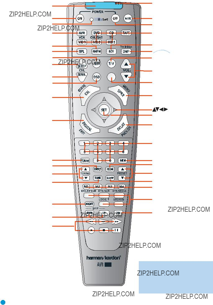
REMOTE CONTROL FUNCTIONS
The AVR 145 remote is capable of controlling nine devices, including the AVR itself and an iPod docked in the optional The Bridge accessory. During the installation process, you may program the codes for each of your source components into the remote. Each time you wish to use the codes for any component, you will need to first press the Selector but- ton for that component. This changes the button functions to the appro- priate codes for that product.
Each Input Selector has been preprogrammed to control certain types of components, with only the codes specific to each brand and model changing, depending on which product code is programmed. The device types programmed into each selector may not be changed.
DVD: Controls DVD players and recorders.
CD: Controls CD players and recorders.
Tape: Controls cassette decks.
Video 1: Controls VCRs, TiVo and DVRs.
Video 2: Controls cable and satellite television
Video 3: Controls televisions and other video displays.
The Bridge/DMP: Controls an iPod docked in The Bridge.
For example, if you have inserted a disc in your CD player and Iyou would like to skip ahead three tracks, but you then find that the volume is too loud, you would follow this procedure:
1.Press the CD Input Selector to switch to the codes that control your CD player.
2.Press the Play Button (in the Transport Controls section) if the disc is not already playing.
3.Press the Skip Up Button three times to advance three tracks.
4.Press the AVR Button so that you can access the Volume Controls.
5.Press the Volume Down Button until the volume level is satisfactory.
Any given button may have different functions, depending on which component is being controlled. Some buttons are labeled with these functions. For example, the Sleep and DSP Surround Buttons are labeled for use as Channel Up/Down Buttons when controlling a televi- sion or cable box. See Table A8 in the appendix for listings of the different functions for each type of component.
IR Transmitter Lens: As buttons are pressed on the remote, infrared codes are emitted through this lens. Make sure it is pointing toward the component being operated.
EzSet??? Microphone: This microphone ???hears??? the test tone used during the EzSet
Power On Button: Press this button to turn on the AVR or another device. The Master Power Switch on the AVR 145???s front panel must first have been switched on.
Mute Button: Press this button to mute the AVR 145???s speaker and headphones outputs temporarily. To end the muting, press this button or adjust the volume. Muting is also canceled when the receiver is turned off.
Program/EzSet Indicator: This LED lights up or flashes in one of three colors as the remote is programmed with codes, and during the EzSet procedure.
Power Off Button: Press this button to turn off the AVR 145 or another device.
AVR Selector: Press this button to switch the remote to the codes that operate the receiver.
Input Selectors: Press one of these buttons to select a source device, which is a component where a playback signal originates, e.g., DVD, CD, cable TV, satellite or HDTV tuner. This will also turn on the receiver and switch the remote to the codes that operate the source device.
AM/FM Button: Press this button to select the tuner as the source, or to switch between the AM and FM bands.
EzSet (SPL) Button: Press this button to run the EzSet
The Bridge/DMP Selector: Press this button to select an iPod docked in the optional The Bridge as the audio source. The remote will switch to the codes that operate the iPod.
Test Tone: Press this button to activate the test tone for manual out-
TV/Video: This button has no effect on the receiver, but is used to switch video inputs on some video source components.
Sleep Button: Press this button to activate the sleep timer, which shuts off the receiver after a programmed period of time of up to 90 minutes.
Volume Controls: Press these buttons to raise or lower the volume, which will be shown in decibels (dB) in the Message Display.
DSP Surround: Press this button to select a DSP surround mode (Hall 1, Hall 2, Theater).
Channel Level: Press this button to set the output levels for each channel so that all speakers sound equally loud at the listening position. Usually this is done while playing an audio selection, such as a favorite CD, after you have calibrated the levels using EzSet, as described in the Getting Started section.
11
IR Transmitter Lens
Power On
Program/EzSet Indicator
AVR Selector
AM/FM
EzSet (SPL)
Test Tone
Sleep
DSP Surround
Channel Level
Digital Input
Tuning Mode
Direct Station Entry
Tuning
Tone Mode
Night Mode
Track Skip
Transport Controls
EzSet Microphone
Mute
Power Off
Input Selectors
TheBridgeTM /DMP Selector
TV/Video
Volume Control
Not Used
Speaker Setup
Set
Delay
Numeric Keys
Memory
Clear
Preset Stations Selectors
Disc Skip
Macros
Surround Mode Selectors
Dim
145
NOTE: To make it easier to follow the instruc- tions throughout the manual that refer to this illustration, a copy of this page may be down- loaded from the Product Support section at www.harmankardon.com
12

REMOTE CONTROL FUNCTIONS
Speaker Setup: Press this button to configure speaker sizes, that is, the
Navigation and Set Buttons: These buttons are used together to make selections within the
Digital Input Select: Press this button to select the specific digital audio input (or analog audio input) you used for the current source.
Delay: Press this button to set delay times that compensate for placing the speakers at different distances from the listening position, or to resolve a ???lip sync??? issue that may be caused by digital video process- ing. This is done using the
Numeric Keys: Use these buttons to enter radio station frequencies when using the tuner (after pressing the Direct Button), or to select station presets.
Tuning Mode: This button toggles between manual (one frequency step at a time) and automatic (seeks frequencies with acceptable signal strength) tuning mode. It also toggles between stereo and mono modes when an FM station is tuned.
Memory: After you have tuned a particular radio station, press this button, then the numeric keys, to save that station as a radio preset.
Tuning: Press these buttons to tune a radio station. Depending on whether the tuning mode has been set to manual or automatic, each press will either change one frequency step at a time, or seek the next frequency with acceptable signal strength.
Direct: Press this button before using the Numeric Keys to directly enter a radio station frequency.
Clear: Press this button to clear a radio station frequency you have started to enter.
Preset Stations Selector: Press these buttons to select a preset radio station.
Tone Mode: Press this button to access the tone controls (bass and treble). Use the Navigation buttons to make your selections.
Disc Skip: This button has no effect on the receiver, but is used with some optical disc changers to skip to the next disc.
Macros: These buttons may be programmed to execute long com- mand sequences with a single button press. They are useful for pro- gramming the command to turn on or off all of your components, or for accessing specialized functions for a different component than you are currently operating.
Surround Mode Selectors: Press any of these buttons to select a type of surround sound (e.g., multichannel) mode. Choose from the Dolby modes, DTS modes, Logic 7 modes or Stereo modes. Each press of a button will cycle to the next available variant of that mode. Not all modes or mode groups are available with all sources.
Night Mode: Press this button to activate Night mode with specially encoded Dolby Digital discs or broadcasts. Night mode compresses the audio so that louder passages are reduced in volume to avoid disturbing others, while dialogue remains intelligible.
Track Skip: These buttons have no effect on the receiver, but are used with many source components to change tracks or chapters.
Dim: Press this button to partially or fully dim the
Transport Controls: These buttons have no effect on the receiver, but are used to control many source components. By default, when the remote is operating the receiver, these buttons will control a DVD player.
13

INTRODUCTION TO HOME THEATER
The AVR 145 may be the first multichannel surround sound receiver you have owned. Although it has more connections and features than older
If you are already familiar with home theater, you may skip this section and proceed to the Connections section on page 15.
Typical Home Theater System
A home theater typically includes your audio/video receiver, which con- trols the system; a DVD player; a source component for television broad- casts, which may be a cable box, a satellite dish receiver, an HDTV tuner or simply an antenna connected to the TV; a video display (television); and loudspeakers.
All of these components are connected by various types of cables for audio and video signals.
Multichannel Audio
The main benefit of a home theater system is that several loudspeakers are used in various locations around the room to produce ???surround sound.??? Surround sound helps to immerse you in the musical or film presentation for increased realism.
The AVR 145 may have up to five speakers connected directly to it (plus a subwoofer). Each speaker is powered by its own amplifier chan- nel inside the receiver. When more than two speakers are used, it is called a multichannel system.
???Front Left and Right ??? The main speakers are used the same way as in a
???Center ??? The center speaker is usually placed above or below the video screen, and is used mostly for dialogue in movies and television programs. This placement allows the dialogue to originate near the actors??? faces, for a more natural sound.
???Surround Left and Right ??? The surround speakers are used to improve directionality of ambient sounds. In addition, by using more loudspeakers in the system, more dynamic soundtracks may be played without risk of overloading any one speaker.
Many people expect the surround speakers to play as loudly as the front speakers. Although all of the speakers in the system will be cali- brated to sound equally loud at the listening position, most artists use the surround speaker for ambient effects only, and they program their materials to steer very little sound to these speakers.
???Subwoofer ??? A subwoofer is a
(LFE) channel which is directed only to the subwoofer. The LFE chan- nel packs the punch of a rumbling train or airplane, or the power of an explosion, adding realism and excitement to your home theater. Many people use two subwoofers, placed on the left and right sides of the room, for additional power and even distribution of the sound.
Surround Modes
There are different theories as to the best way to present surround sound and to distribute soundtrack information among the various speakers. A variety of algorithms have been developed in an effort to accurately reproduce the way we hear sounds in the real world. The result is a rich variety of surround mode options. Some modes are selected automatically, depending on the signal being received from the source. In many cases, you may select a surround mode manually.
Several companies have taken surround sound in slightly differing direc- tions. It is helpful to group the numerous surround modes either by their brand name, or by using a generic name:
???Dolby Laboratories, Inc. Modes ??? Dolby Digital, Dolby Pro Logic II, Dolby Virtual Speaker, Dolby Headphone
???DTS Modes ??? DTS, DTS Neo:6, DTS 96/24
???Harman International (Harman Kardon???s Parent Company) ???
Logic 7
???DSP Modes ??? Generic modes that include Hall 1, Hall 2 and Theater
???Stereo Modes ??? Generic modes that expand upon conventional two- channel stereo, including DSP Surround Off, Analog Bypass Surround Off and
Table 4 on pages 38 ??? 40 contains detailed explanations of the differ- ences between the various mode groups, and the mode options avail- able within each group. Digital modes, such as Dolby Digital and DTS, are only available with specially encoded programs, such as DVDs and digital cable or satellite television. Other modes may be used with vari- ous digital and analog signals to create a different surround presenta- tion, or to use a different number of speakers. Surround mode selection depends upon the number of speakers in your system, the materials you are watching or listening to, and your personal tastes. Feel free to experiment.
14
CONNECTIONS
There are different types of audio and video connections used to con- nect the receiver to the speakers and video display, and to connect the source devices to the receiver. To make it easier to keep them all straight, the Consumer Electronics Association (CEA) has established a
Audio Connections
Digital Audio Connections
Coaxial
OpticalInput  Output
Video Connections
Table 1??? Connection Color Guide
Types of Cables
This section will briefly review different types of cables and connections that you may use to set up your system.
Speaker Cables
Speaker cables carry an amplified signal from the receiver???s speaker ter- minals to each loudspeaker. Speaker cables generally contain two wire conductors, or leads, inside plastic insulation. The two conductors are usually differentiated in some way, by using different colors, or stripes, or even by adding a ridge to the insulation. Sometimes the actual wires are different, one being copper red and the other silver.
The differentiation is important because each speaker must be connect- ed to the receiver???s
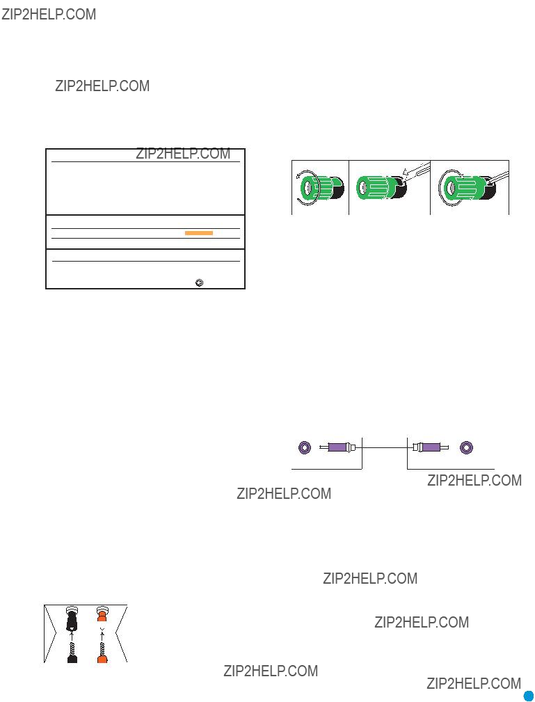
Always connect the positive terminal on the loudspeaker, which is usually colored red, to the positive terminal on the receiver, which is colored as shown in the Connection Color Guide (Table 1). Similarly, always con- nect the black negative terminal on the speaker to the black negative terminal on the receiver.
Bare wire cables are installed as follows:
1.Unscrew the terminal cap until the
2.Insert the bare end of the wire into the hole.
3.Screw the cap back into place until the wire is held snugly.
Figure 2 ???
Subwoofer
The subwoofer is a specialized type of loudspeaker that is usually con- nected in a different way. The subwoofer is used to play only the low frequencies (bass), which require much more power than the other speaker channels. In order to obtain the best results, most speaker manufacturers offer powered subwoofers, in which the speaker contains its own amplifier on board. Sometimes the subwoofer is connected to the receiver using the front left and right speaker outputs, and then the front left and right speakers are connected to terminals on the sub- woofer. More often, a
from the receiver???s Subwoofer Output to a corresponding jack on the subwoofer.
Although the subwoofer output looks similar to the analog audio jacks used for the various components, it is filtered and only allows the low frequencies to pass. Don???t connect this output to your other devices.
Although doing so won???t cause any harm, performance will suffer.
Figure 3 ??? Subwoofer
Connecting Source Devices to the AVR
The AVR 145 is designed to process audio and video input signals, playing back the audio and displaying the video on a television or moni- tor connected to the AVR. These signals originate in what are known as ???source devices,??? including your DVD player, CD player, DVR (digital video recorder) or other recorder, tape deck, game console, cable or satellite television box or MP3 player. Although the tuner is built into the AVR, it also counts as a source, even though no external connections are needed, other than the FM and AM antennas.
 +
+
Figure 1 ???
Terminals With Banana Plugs
The AVR 145 uses
Banana plugs are simply plugged into the hole in the middle of the terminal cap.
In general, separate connections are required for the audio and video portions of the signal. The types of connections used depend upon what???s available on the source device, and for video signals, the capabili- ties of your video display.
15

CONNECTIONS
Audio Connections
There are two formats for audio connections: digital and analog. Digital audio signals are of higher quality, and are required for listening to sources encoded with digital surround modes, such as Dolby Digital and DTS. There are two types of digital audio connections commonly used: coaxial and optical. Either type of digital audio connection may be used for each source device, but never both simultaneously for the same source. However, it???s okay to make both analog and digital audio con- nections at the same time to the same source.
Digital Audio
Coaxial digital audio jacks are usually
Coaxial digitalCoaxial audio cable 


Figure 4 ??? Coaxial Digital Audio
Optical digital audio connectors are normally covered by a shutter to protect them from dust. The shutter opens as the cable is inserted. Input connectors are
Multichannel analog connections are used with advanced sources where the digital content is
Front Surround Center
Multichannel analog audio cable (RCA)
Subwoofer
Figure 7 ??? Multichannel Analog Audio
Figure 8 ??? The Bridge
Harman Kardon receivers also include a proprietary, dedicated audio connection called ???The Bridge/DMP???. If you own an iPod with a dock connector, you may separately purchase The Bridge and connect it to The Bridge/DMP port on the receiver. Dock your iPod (not included) in The Bridge, and you may listen to your materials through your
Optical digital audio cable
Optical
Video Connections
Figure 5 ??? Optical Digital Audio
Due to the nature of digital signals as binary bits, they aren???t subject to signal degradation the way analog signals are. Therefore, the quality of coaxial and optical digital audio connections should be the same,
although it is important to limit the length of the cable. Whichever type of connection you choose, Harman Kardon recommends that you always select the highest quality cables available within your budget.
Analog Audio
Analog connections require two cables, one for the left channel (white) and one for the right channel (red). These two cables are often attached to each other for most of their length. Most sources that have digital audio jacks also have analog audio jacks, although some older types of sources, such as tape decks, have only analog jacks. For sources that are capable of both digital and analog audio, you may wish to make both connections. If you wish to record materials from DVDs or other
Figure 6 ??? Analog Audio
Although some sources produce an audio signal only (e.g., CD player, tape deck), many sources output both audio and video signals (e.g., DVD player, cable television box, HDTV tuner, satellite box, VCR, DVR). In addition to the audio connection, you will need to connect one type of video connection for each source (never more than one at the same time for any source).
There are three types of analog video connections: composite video,
Composite video is the basic connection most commonly available. The jack is usually
Composite video cable
Figure 9 ??? Composite Video
16

CONNECTIONS
Composite video cable
Figure 10 ???
Component video separates the video signal into three components ??? one luminance (???Y???) and two subsampled color signals (???Pb??? and ???Pr???) ??? that are transmitted using three separate cables. The ???Y??? cable is color- coded green, the ???Pb??? cable is colored blue and the ???Pr??? cable is col- ored red.
Component video cable
Figure 11 ??? Component Video
If it???s available on your video display, component video is recom- mended as the best quality connection, followed by
Antennas
The AVR 145 uses separate terminals for the included FM and AM antennas that provide proper reception for the tuner.
The FM antenna uses a
Figure 12 ??? FM Antenna
The AM loop antenna needs to be assembled. Then connect the two leads to the screw terminals on the receiver.
Figure 13 ??? AM Antenna
The
to the AVR using this port. Complete instructions will be provided at that time.
17

SPEAKER PLACEMENT
Before you begin to connect cables, it is important to set up your speakers in their correct locations in the room.
Optimally, the speakers should be placed in a circle with the listening position at its center. The distance from the listening position to the video display forms the radius of the circle.
The speakers should be angled so that they directly face the listening position.
The center speaker is placed either on top of, below or mounted on the wall above or below the video display screen.
The front left and right speakers are placed along the circle, about 30 degrees from the center speaker and angled toward the listener.
It is best to place the front left/right and center speakers as close to the same height as possible, preferably at about the same height as the lis- tener???s ears. In any event the center speaker should be no more than two feet above or below the left/right speakers.
The side surround speakers should be placed 110 degrees from the center speaker, that is, slightly behind and angled toward the listener. If this isn???t feasible, place the surround speakers behind the listener, with each surround speaker facing the
The subwoofer???s location is less critical, since
NOTE: Your receiver will sound its best when the same model loudspeaker is used for all positions (other than the subwoofer). If that isn???t possible, try to use speakers made by the same manufacturer.
SUB
C
SL  SR
SR
18

You are now ready to connect your various components to your receiver. Before beginning, make sure that all components, including the AVR 145, are turned completely off and their power cords are unplugged. Don???t plug any of the power cords back in until you have finished making all of your connections.
Remember that your receiver generates heat while it is playing. Select a location that leaves several inches of space on all sides of the receiver. It is preferable to avoid completely enclosing the receiver inside a cabinet. It is also preferable to stack components on separate shelves rather than directly on top of the receiver. Some surface finishes are delicate. Try to select a location with a sturdy surface finish.
Step One ??? Connect the Speakers
If you have not yet done so, place your speakers in the listening room as described in the Speaker Placement section above.
Connect the center, front left, front right, surround left and surround right loudspeakers to the corresponding speaker terminals on the AVR 145. Remember to maintain the proper polarity by always connecting the positive and negative terminals on each speaker to the positive and negative terminals on the receiver. Use the Connection Color Guide
on page 15 as a reference.
INSTALLATION
Step Three ??? Connect the Antennas
Connect the FM and AM antennas to their terminals.
AVR 145
AM
FM
Figure 17 ??? Antenna Connections
AVR 145
AVR 145
C
Figure 15 ??? Speaker Connections
Step Two ??? Connect the Subwoofer
Connect the Subwoofer Output on the AVR 145 to the
AVR 145
SUB
Figure 16 ??? Subwoofer Connection
Step Four ??? Connect the Source Components
Use the worksheets in the Appendix to note which connections you will use for each of your source devices.
For each source, select a source input (Video 1, Video 2, Video 3, etc.). In Table 2 we recommend connecting certain types of sources to certain source inputs to make it easier to program and use the remote control.
Decide which audio connections you will use. If your source device has them, use either the coaxial digital or the optical digital audio connec- tion. Referring to Table 2, we recommend you connect the DVD source to the Coaxial 1 input jack, and the source designated Video 2 to the Optical 2 input jack. However, you may make whatever connections are best for your system.
In addition to the digital audio connections, we recommend that you connect the analog audio connections for each source, as a backup to the digital connections. For sources that don???t have digital audio outputs, you must use the analog audio connections.
For each video source, select one type of video connection. Component video is preferred, but both your source device and your video display must have this type of video capability. If either device does not, then use
Referring to Table 2, we recommend that you connect the DVD source to the Component Video 1 inputs, and any one source designated as Video 1, Video 2 or Video 3 to the Component Video 2 inputs. However, you may make whatever video connections are best for your system.
19
INSTALLATION
NOTE: It???s possible for a source to use none of the connections named for that source. For example, you might connect your DVD player to the Component Video 1 inputs and the Coax 1 digital audio input. However, we will refer to this source as ???DVD???, and in Step Five of the Initial Setup section you will pro- gram the receiver so that these connections are assigned to the DVD source. When you select ???DVD??? as your source using the front panel or the remote, the correct connections for your DVD player will be used.
We recommend connecting your various sources using the connections shown in Table 2 below in order to simplify programming your receiver and remote control. However, you may connect any device to any source input.
Table 2 ??? Recommended Source Component Connections
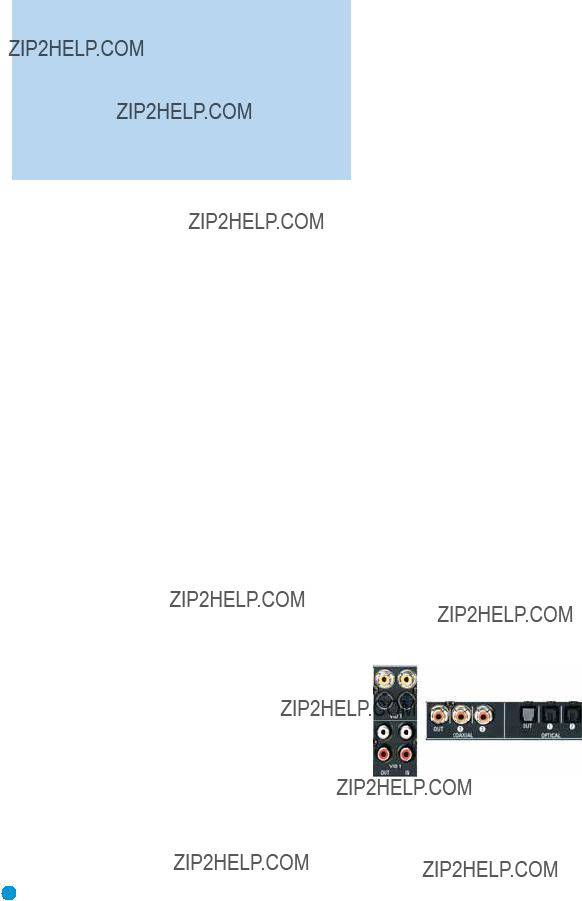
Video 1 Source
Since this source includes audio and video recording output jacks, it is best suited to a video recorder, such as your VCR or DVR.
Referring to Table 2, connect your recorder to the Video 1 Analog Audio inputs and outputs and to either the Coax 2 or Optical 2 digital audio input (and corresponding digital audio output). Use either the Video 1
Figure 18 ??? Video 1 A/V Inputs and Outputs, and Digital Audio Inputs
Remember to connect the audio and video output jacks on your recorder to the Video 1 or digital audio input jacks on the AVR, and the audio and video input jacks on your recorder to the Video 1 or digital audio output jacks on the AVR.
20
INSTALLATION STEPS
NOTE: It isn???t possible to make recordings using component video connections. Keep this in mind as you connect other source devices that you may wish to make recordings from.
Video 2 Source
The Video 2 source is used only for playback, never recording. The AVR 145 remote control is programmed to operate many brands and models of cable and satellite television devices, and we recommend connecting your cable or satellite
Referring to Table 2, connect your
DVD
The DVD source is used for a DVD player. If you have a more advanced multichannel device, such as a
Referring to Table 2, connect your DVD player to the DVD Analog Audio inputs and to the Coaxial 1 Digital Audio input. If possible, use the Component Video 1 inputs. Otherwise, connect the DVD player???s
Figure 21 ??? DVD A/V, DIgital Audio and Component Video Inputs
If your DVD player plays multichannel lossless discs, such as SACD or
Figure 19 ??? Video 2 A/V, DIgital Audio and Component Video Inputs
NOTE: If you receive your television programming using your TV with an antenna or direct cable connection, then you will need to connect the analog and optical digital audio (if available on your TV) outputs to the Video 2 Analog Audio inputs and to the Optical 1 Digital Audio input. Do not connect any video output on the television set to any video input on the receiver. See Step Five for information on connecting the receiver???s video monitor outputs to the television.
Figure 22 ???
CD
The CD source is used for a strictly audio device, such as a CD player.
Referring to Table 2, connect your CD player to the CD Analog Audio inputs and to the Coaxial 2 or Optical 2 Digital Audio input.
Video 3 Source
The Video 3 source is used only for playback, never recording. It is also generally reserved for components that are only temporarily connected to the receiver, such as cameras and game consoles. When not in use, you may place the supplied covers over the
Referring to Table 2, connect your camera or game console to the Video 3 Analog Audio inputs and to either the Coaxial 3 or Optical 3 digital audio input. If possible, use the Component Video 2 inputs. Otherwise, connect the component???s
Figure 20 ??? Video 3 A/V and Digital Audio Inputs
Figure 23 ??? CD Audio Inputs and Digital Audio Inputs
No video connections are made, although if your system has unusual requirements, you may connect a video device using component video outputs to the Component Video 2 inputs on the receiver, if those jacks are not in use by another device.
Tape
The Tape source is used for
Referring to Table 2, connect your recorder to the Tape Analog Audio inputs and outputs, and to either the Coax 2 or Optical 2 Digital Audio input (and corresponding digital audio output).
21

INSTALLATION
Figure 24 ??? Tape Audio Inputs and Outputs, and Digital Audio Inputs and Outputs
Remember to connect the output jacks on your recorder to the Tape or digital audio input jacks on the AVR, and the input jacks on your recorder to the Tape or digital audio output jacks on the AVR.
No video connections are made, although if your system has unusual requirements, you may connect a video device using component video outputs to the component Video 2 inputs on the receiver, if those jacks are not in use by another device.
TheBridgeTM
With Harman Kardon???s optional The Bridge, you can listen to audio stored on your iPod (not included), use your AVR 145 remote control to operate the iPod, and even charge the iPod while it???s docked in The Bridge.
Simply plug the proprietary cable from The Bridge into the special The Bridge/DMP connector on the rear of the AVR 145???s. Refer to the owner???s manual for The Bridge to select the appropriate insert to match your iPod.
Figure 25 ??? The Bridge/DMP Connector
Step Five ??? Connect Video Display
Only video connections should be made between the receiver and your video display (TV), unless your TV is the source for your television pro- gramming (see note above).
You will need to make a video connection for each type of video used for your sources. In addition, even if you didn???t use
First, determine what types of video your display is capable of handling. Remember that component video is preferred, followed by
Next, note which types of video connections you used for your source devices. Make sure you didn???t use a better type of video connection for a source than your video display can handle. If so, you will need to dis- connect the source and use a video connection that???s compatible with your display.
If you used component video for any sources, connect the Component Video Monitor outputs on the receiver to one set of component video inputs on your display. Make a note of how these inputs are labeled on the display.
Figure 26 ??? Component Video Monitor Outputs
If you used
If you used composite video for any sources, connect the composite video Monitor output on the receiver to a composite video input on the display. Again, make a note of how this input is labeled on the display.
Figure 27 ???
Consult the manual for your TV to make sure you understand how to select each video input. As you play different source devices that use different types of video connections, you will need to remember to select the correct video input on your video display.
Step Six ??? Plug in AC Power
Having made all of your wiring connections, it is now time to plug each component???s AC power cord into a working outlet.
You may plug one device into the AC Switched Accessory Outlet on the rear of the AVR 145. Make sure this device draws no more than 50 watts. The device should have its mechanical or master power switch turned on, and it will power on any time the AVR 145 is turned on.
Figure 28 ??? Switched AC Accesssory Outlet
Before plugging the AVR 145???s AC Power Cord into an electrical outlet, make sure that the Master Power Switch on the front panel is popped out so that the word OFF appears on its top. Gently press the button to turn the switch off. This will prevent the possibility of damaging the AVR in case of a transient power surge.
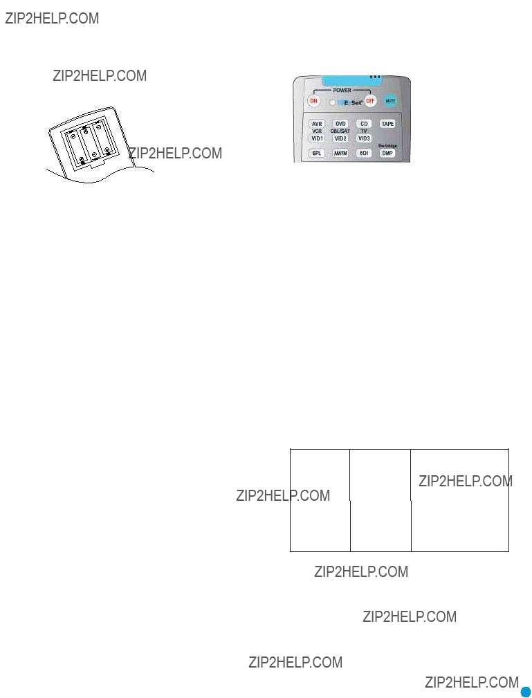
Step Seven ??? Insert Batteries in Remote
The AVR 145 remote control uses three AAA batteries, which are included.
To remove the battery cover located on the back of the remote, firmly press the ridged depression and slide the cover towards the top of the remote.
22
INSTALLATION
Insert the batteries as shown in the diagram, making sure to observe the correct polarity.
Figure 29 ??? Remote Battery Compartment
When using the remote, remember to point the lens toward the front panel of the AVR 145. Make sure no objects, such as furniture, are blocking the remote???s path to the receiver. Bright lights, fluorescent lights and plasma video displays may interfere with the remote???s functioning. The remote has a range of about 20 feet, depending on the lighting conditions. It may be used at an angle of up to 30 degrees to either side of the AVR.
If the remote seems to operate intermittently, or if pressing a button on the remote does not cause the AVR Selector or one of the Input Selectors to light up, then make sure the batteries have been inserted correctly, or replace all three batteries with fresh ones.
Step Eight ??? Program Sources Into the Remote
The AVR 145 remote is capable of controlling not only the receiver, but it may also be programmed to control many brands and models of VCRs, DVD players, CD players, cable boxes, satellite receivers, cassette decks and TVs, as well as The Bridge.
It may help to think of the remote as a book with pages. Each page rep- resents the button functions for a different device. In order to access the functions for a particular device, you first need to turn to that page. This is done by pressing the AVR Button to access the codes that control the receiver, or the Input Selector buttons to access the codes for the devices programmed into the remote.
At the factory, the AVR 145???s codes and the codes to control an iPod docked in The Bridge are preprogrammed, and the codes for many Harman Kardon DVD and CD players are also preprogrammed. If you have other source devices in your system, follow these steps to pro- gram the correct codes into the remote.
1.Using the codes in Tables
2.Turn on your source device.
3.Put the remote into Program mode by pressing and holding the Input Selector and the Mute button simultaneously until the LED on the remote starts to flash, and then releasing the buttons.
Figure 30 ??? Input Selectors
4.Enter a code from Step 1 above.
a)If the device turns off, then press the Input Selector again to accept the code, which will flash. The remote will exit the Program mode.
b)If the device does not turn off, try entering another code. If you run out of codes, you may search through all of the codes in the remote???s library for that product type by pressing the ??? or ?? button repeatedly until the device turns off. When the device turns off, enter the code by pressing the Input Selector, which will flash. The remote then exits Program mode.
5.Once you have accepted a code, it???s a good idea to try using some other functions to control the device. Sometimes manufacturers use the same Power code for several different models, while other codes will vary. You may wish to repeat this process until you???ve pro- grammed a satisfactory code set that operates most of the functions you frequently use.
6.You may find out which code number you have programmed by pressing and holding the Input Selector and Mute Button simultane- ously to enter the Program mode. Then press the Set Button, and the LED will blink in the code sequence. One blink represents ???1???, two blinks for ???2???, and so forth. A series of many fast blinks represents ???0???. Record the codes programmed for each device here.
Table 3 ??? Remote Control Codes
If you are unable to locate a code set that correctly operates your source device, it will not be possible to use the AVR remote to control that device. However, you may still connect the source to the AVR 145 and operate it using the device???s original remote control. Alternatively, you may wish to consider purchasing Harman Kardon???s optional TC 30
23

INSTALLATION
Most of the button labels on the remote describe the button???s function when used to control the AVR 145. However, the button may perform a very different function when used to control another device. Refer to the Remote Control Function List, Table A8 in the Appendix, for a list of each button???s functions with the various product types.
If you wish, you may program Macros, which are preprogrammed code sequences that execute many code commands with a single button press. You may also program
NOTE: The AVR 145 remote is preprogrammed to operate the transport controls of Harman Kardon DVD players when the AVR or the Video 2 (cable/satellite) or Video 3 (TV) source is selected. The volume and mute controls operate the AVR when any device except Tape has been selected. You may change this
Step Nine ??? Turn On the AVR 145
Two steps are required the first time you turn on the AVR 145.
1.Gently press the Master Power Switch until the word OFF is no longer visible. The Power Indicator above the two power switches should light up in amber. This indicates that the AVR is in Standby mode and is ready to be turned on. Normally, you may leave the Master Power Switch in the ON position, even when the receiver is not being used.
Figure 33 ??? AVR and Input Selectors
NOTE: Any time you press one of the Input Selectors on the remote (i.e., DVD, CD, TAPE, VID1, VID2 or VID3), the remote will switch modes so that it will only transmit the codes pro- grammed to operate that device. In order to control the receiver, you will need to press the AVR button to return the remote to AVR mode.
Figure 31 ??? Power Switches
2.There are several ways in which the AVR 145 may be turned on from Standby mode.
a)Press the Standby/On Switch on the front panel.
b)Press the Source Select Button on the front panel.
Figure 32 ??? Source Select Button
c)Using the remote, press any one of these buttons: AVR, DVD, CD, TAPE, VID1, VID2, VID3, AM/FM or 6/8CH.
24

Before you begin enjoying your new receiver, a few adjustments should be made to configure the AVR 145 to match your actual system.
Make sure that you have connected a video display to either the S- video or composite video monitor output on the receiver. When you turn on your display and the AVR, you should see a blue screen. A message may appear briefly at the bottom of the screen. This message is part of the
Although it???s possible to configure the AVR using only the remote and the
Using the
The full OSD system is accessed by pressing the OSD Button on the remote. While the full OSD system is in use, it isn???t possible to see any video programming. In addition, an OSD ON message will appear on the front panel of the receiver to remind you to use a video display.
Figure 34 ??? Navigation Buttons
The Master Menu will always be displayed when you first press the OSD Button. Use the ???????? Buttons on the remote to point the cursor to dif- ferent lines in the menu. Press the Set Button on the remote to select a line that has no setting to be adjusted, such as one of the submenus listed in the Master Menu, or a line that returns you to a previous menu. Within the submenus, after you have positioned the cursor at a particular line item, you will need to use the ???/??? Buttons on the remote to change a setting. When the desired setting appears, use the ???????? Buttons to navigate to another line item. Except for the TITLE setting in the INPUT SETUP menu, there is no need to press the Set Button after your desired setting appears.
NOTE: The ???/??? and Set Buttons on the front panel have no effect on the OSD system.
INITIAL SETUP
The Master Menu allows access to four submenus: Input Setup, Surround Select, Manual Setup and System Setup.
Figure 35 ??? Master Menu Screen
If you are an experienced home theater user, you may prefer to use the menus in this order:
1.System Setup (described in Advanced Functions section)
2.Manual Setup (described here and in Advanced Functions)
3.Input Setup (described in this section)
4.Surround Select (see Advanced Functions section)
However, we recommend that most users follow the instructions in this INITIAL SETUP section to configure a basic home theater system. You may return to these menus at any time to make additional adjustments.
This section requires that you complete all of the steps in the Installation section that apply to your receiver. You should have connected all of your loudspeakers and a video display, as well as your source devices. You should be able to turn on the receiver and view a blue screen on your video display. If necessary, reread the Installation Section before con- tinuing.
Step One ??? Determine Speaker Size
The AVR 145 can???t detect how many speakers you???ve connected to it; nor can it determine their capabilities. For this part of the system setup, you will need to consult the owner???s guide for each of your speakers. If you don???t have the guide, you may be able to obtain the speaker???s tech- nical specifications from the manufacturer???s Web site, or by contacting the manufacturer directly.
The specification you???re looking for is the frequency response, which is usually given as a range, e.g., 100Hz ??? 20kHz (??3dB). This specifica- tion tells you whether the speaker is able to play sounds that are very high- or
25

INITIAL SETUP
The frequency response for your subwoofer will usually cover only the very lowest frequencies, since the subwoofer is only designed to play bass materials. A typical frequency response for a subwoofer is 25Hz ??? 150Hz. In this case, the higher number is most important and should be noted in the worksheet.
The purpose of programming this information into the AVR 145 is to program the receiver???s bass management, which determines which speakers the receiver will use to play back the
If you send the lowest notes to small satellite speakers, you won???t hear these notes very well, and you may even damage the speaker by going beyond its capabilities. If you send the highest notes to the
With proper bass management, the AVR 145 divides the source signal at a crossover point. All information above the crossover point is played through the satellite speaker (front left/right, center or surround left/right), and all information below the crossover point is played through the subwoofer. This enables each loudspeaker in your system to perform at its best, delivering an enjoyable sound experience.
Step Two ??? Measure Speaker Distances
Ideally, all of your speakers were placed in a circle, each at the same distance from the listening position. However, your room may not be ideal, and you may have had to place some speakers a little further away than others. This could affect the overall sound of the receiver, as sounds that are supposed to arrive simultaneously from different speakers blur, due to different arrival times.
Fortunately, the AVR 145 has a delay adjustment that enables the receiver to compensate for
Before you begin making adjustments, measure the distance from each speaker to the listening position, and note it in the worksheets in the appendix. Even if all of your speakers are the same distance from the listening position, you should enter your speaker distances.
Step Three ??? Manual Setup Menu
Now you are ready to program these adjustments into the receiver. It???s best to sit in the usual listening position and make the room as quiet as possible. Don???t worry if you make a mistake; you can always go back and change these settings.
With the receiver and video display turned on, press the OSD Button on the remote. Use the ?? Button on the remote to move the cursor to the MANUAL SETUP line, and press the Set Button to display the Manual Setup menu.
Figure 36 ??? Manual Setup Menu Screen
The Manual Setup menu is the gateway to four submenus. The first three menus ??? Speaker Size, Speaker
Speaker Size Menu
Press the Set Button to display the Speaker Size submenu.
Figure 37 ??? Speaker Size Menu Screen
The Speaker Size menu lists each of the speaker groups. You will be programming the correct setting for each group, indicating how many speakers are in your system and what their capabilities are, based on the information you obtained in Step One ??? Determine Speaker Size. Each of the main speaker groups can be set to one of three settings:
LARGE, SMALL or NONE. These settings don???t refer to the physical size of the speaker, but rather to the size of the frequency range of each speaker. These may or may not turn out to be the same.
If the lower number of the frequency response for your speakers is less than 100Hz, choose the LARGE setting. If this number is 100Hz or greater, choose the SMALL setting. If you don???t have a speaker con- nected to that position, choose NONE.
As you can see, the system requires you to use both speakers in a pair. For example, you can???t connect just a front left speaker without a right speaker, or just a right surround (rear) speaker without a left one. However, you can connect only the front speakers, or both front and surround speakers without a center, or the front left/right and center speakers without any surrounds.
26
LEFT/RIGHT: This line tells the AVR 145 the capabilities of your front left and right speakers. Use the ???/??? Buttons to select either SMALL or LARGE for these speakers.
CENTER: Move the cursor to the line for the center speaker, and use the ???/??? Buttons to select a setting for this speaker.
NOTE: If the receiver is currently in one of the Logic 7 surround modes, which will be the case the first time you turn on the receiver, you won???t be able to set the center speaker to LARGE, due to the requirements of the Logic 7 processor. You may use the SMALL setting instead. As you listen to the receiver, if you find the SMALL setting is not satisfactory, change the surround mode to one of the Dolby Pro Logic II modes (using the Surround Select menu, accessible from the Master Menu), and then you may come back to this menu and change the center speaker to the LARGE setting.
SURROUND: Move the cursor to the line for the surround, or rear, speakers, and use the ???/??? Buttons to select a setting for these two speakers.
SUBWOOFER: Move the cursor to the line for the subwoofer, which is programmed a little differently. The subwoofer???s ???size??? setting depends upon how you programmed the front left and right speakers.
???If you set the front speakers to SMALL, the subwoofer setting will be SUB, and you won???t be able to change it. All
???If you set the front speakers to LARGE, you may select from three possible settings for the subwoofer.
???L/R+LFE: This setting sends all
???LFE: This setting plays
???NONE: This setting steers all
NOTE: If you are using a Harman Kardon HKTS speaker sys- tem, select the SMALL setting for the LEFT/RIGHT, CENTER and SURROUND lines, and the subwoofer will automatically be set to SUB.
BASS MGR: This advanced setting is used if you wish to configure your speakers differently for different sources. For example, you may prefer to set your speakers to LARGE while listening to CDs from your CD player. By changing this setting to INDEPENDENT, you may have different set-
INITIAL SETUP
tings for your CD player and your DVD player or other devices. We rec- ommend that you leave this setting at its factory default of GLOBAL until you have more experience with the AVR.
Move the cursor to the BACK TO MANUAL SETUP line and press the Set Button to return to the Manual Setup Menu.
NOTE: The Speaker/Channel Indicators on the front panel of the receiver will display the speaker size settings as follows. For each speaker configured as SMALL, a single box will appear in the position for that speaker. For each speaker configured as LARGE, a double box will appear in its position. If a speaker is configured as NONE, no box will appear. The subwoofer will be indicated by a single box, or no box if no subwoofer has been configured. The letters inside the boxes appear when a digital signal is being received that has that channel discretely encoded. The letters flash when the signal is not present, such as when a DVD is paused.
Figure 38 ??? Speaker/Channel Input Indicators
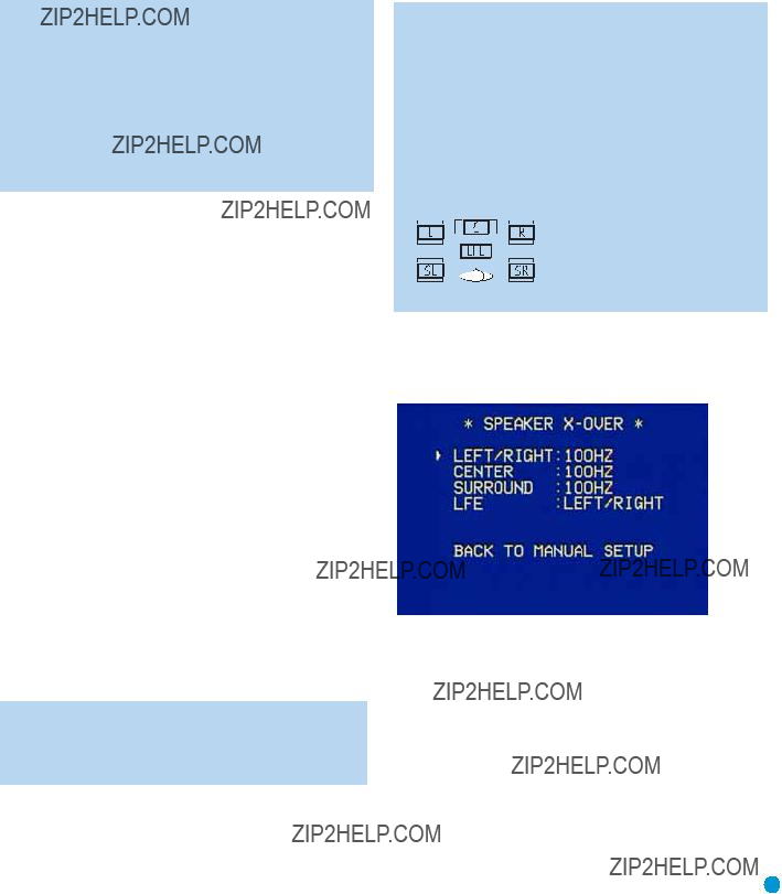
Speaker Crossover Menu
On the Manual Setup menu, move the cursor to the SPEAKER
Figure 39 ??? Speaker Crossover Menu Screen
Setting the Speaker Crossover menu correctly ensures that your speakers are properly used so that they sound their best. Although you could skip this step the first time you use the receiver, we recommend that you take the few extra minutes to enter the correct crossover settings.
You may select from seven possible settings: 40Hz, 60Hz, 80Hz, 100Hz, 120Hz, 150Hz or 200Hz. Depending upon the frequency response of your speakers which you recorded in Step One ??? Determine Speaker Size, for each speaker group select the number that matches or is just above the low end of your speaker???s frequency response.
27

INITIAL SETUP
The LFE line sets the frequency for a
Looking at each of your three
Move the cursor to the BACK TO MANUAL SETUP line and press the Set Button to return to the Manual Setup menu.
Delay Adjust Menu
As explained above in Step Two ??? Measure Speaker Distances, some- times the speakers are placed at different distances from the listening position, which can muddy the sound, as sounds are heard earlier or later than desired.
Even if all of your speakers are placed the same distance from the lis- tening position, you should not skip this menu.
On the Manual Setup menu, move the cursor to the DELAY ADJUST line and press the Set Button to display the Delay Adjust menu.
Figure 40 ??? Delay Adjust Menu Screen
This menu requires you to enter the distance from each speaker to the listening position, which you measured in Step Two ??? Measure Speaker Distances.
The default unit of measurement is in feet. If you wish to change the unit to meters, move the cursor down to the UNIT line, and use the ???/??? Buttons to change the unit to METER.
Use the ???/?? Buttons to move the cursor to the FL (front left) line; then use the ???/??? Buttons to change the measurement as needed. Use the ???/?? Buttons to move to each speaker in turn ??? CEN (center), FR (front right), SR (surround right), SL (surround left) and SUB (subwoofer).
DELAY RESET: This line is used if you wish to reset all of the speaker delay settings to the factory default of 10 feet (3.0 meters) at once. Use the ???/??? Buttons to change the setting of OFF to ON. If you change any speaker???s setting, this line will automatically revert to OFF.
A/V SYNC DELAY: This line allows you to compensate for a situation in which one of your source devices, or your video display, introduces a significant amount of video processing that causes the audio and video parts of the signal to get out of sync. This is known as a ???lip sync??? prob- lem. You may delay the audio for all channels by up to 80 milliseconds to compensate.
NOTE: We recommend that you adjust the A/V Sync Delay using the Delay Button on the remote, rather than in this menu, so that you can view the picture while adjusting the audio delay. With the program playing, press the Delay Button, and the A/V SYNC DELAY message will appear on the front panel and in the
Move the cursor to the BACK TO MANUAL SETUP line and press the Set Button to return to the Manual Setup menu, or simply press the OSD Button to exit the menu system.
Step Four ??? EzSet Output Level Calibration
This is an important step in the configuration process, and should not be skipped.
By now you should have connected all of your speakers and sources and your video display. You should have turned on the receiver and used the Manual Setup menus to program each of your speakers as Large or Small.
Sit in the listening position with the remote control, and make sure to eliminate external noises for the few minutes needed to run the EzSet procedure.
Use the volume control buttons on the remote to adjust the volume to
Now point the remote at the receiver and press the SPL Button until the LED blinks, then press the ???5??? Key. The procedure works best if you hold the remote at about ear level, pointed toward the receiver. Try not to tilt the remote out of line with the IR receiver on the AVR???s front panel.
Figure 41 ??? EzSet (SPL) Button
28

INITIAL SETUP
The receiver will generate a loud test tone, which sounds like static. In fact, it???s a tone that simultaneously uses all frequencies from 20Hz to 20kHz.
The tone should be heard first through the front left speaker. It will circu- late to the other speakers in this order: front left, center, front right, sur- round right, surround left. The tone pauses for a few moments at each speaker position, while a microphone built into the remote measures the loudness (sound pressure level) of the tone. The remote contains pro- gramming that compares the loudness of the tone at each position to a reference and sends commands to the receiver to adjust the output level for that channel until the tone matches the reference.
A
The result is that each speaker will be heard equally loud at the listening position. This is important for movie directors, who adjust the loudness of each channel in the recording to produce a desired sound presenta- tion. Usually, the director reduces the loudness of, or even the presence of information in the surround channels so as not to distract the viewer from the main action taking place on screen. If the test tone sounds as loud in the rear speakers as it does coming from the other speakers, then the receiver is performing correctly.
As the tone circulates to each speaker position, the
The
As the levels are being adjusted, the LED on the remote will change until it is green for all channels.
The tone will circulate a second time, and then the procedure will end.
NOTE: In order to optimize performance for each of the many surround modes and their variants, the AVR 145 is able to associate a different set of output level settings with each mode. While this results in extremely realistic reproduction of surround sound presentations, it does require that you determine the cor- rect settings for each surround mode.
The first time you turn on the AVR, it will default to the Logic 7 Music mode. Harman Kardon recommends that at initial
using the
If you prefer, you may run EzSet for the major surround modes, such as Logic 7 (select either Cinema or Music), Dolby (select Dolby Pro Logic II Movie) and DTS (select DTS Neo:6). Then you may copy the resulting level settings for the other mode variants within each group.
Advanced users may rerun EzSet for each mode individually.
Step Five ??? Configure Sources
This is the last step in the configuration process.
Press the OSD Button to view the Master Menu. The cursor will be pointing to the INPUT SETUP line, and you need only press the Set Button to display the Input Setup menu.
Figure 42 ??? Input Setup Menu Screen
The first line indicates that the receiver is currently set to the tuner source. In fact, you may hear static if the tuner is set to an unused fre- quency. You will not be able to make any changes to the tuner, other than selecting a component video input or adjusting the tone controls. It is not recommended that you make either of these changes for
the tuner.
Press the ??? Button to view the next source. The sources will be selected in the following order: Tape,
For each of these sources, you may adjust the settings below. At a mini- mum, you should make sure that sources you connected to either of the component video inputs has the correct settings, and that sources you connected to any of the digital audio inputs also display the correct settings. Other settings are optional, and you may adjust them at a later time when you have more experience with the AVR. Refer to the work- sheets you filled out during installation as you assign inputs to each source.
TITLE: You may change the display name for any source (except the tuner). Not only does this enable you to customize your system; it helps
29

INITIAL SETUP
you to select the correct source device even when you have forgotten which physical connections you used.
Move the cursor down to the TITLE line and press the Set Button. A block cursor will blink.
The remaining lines in the Input Setup menu activate the tone controls, and may be skipped at this time. We recommend leaving the tone con- trols at their factory defaults for most listening, in order to enjoy the sound mix created by your favorite movie and music artists. However, if your room or speakers have unusual characteristics, or simply as a mat- ter of personal preference, see the Tone Controls section on page 32 for more information.
You are now ready to begin enjoying your new receiver!
Figure 43 ??? Retitling a Source Input
Now you may use the ???/?? Buttons to scroll through the alphabet in upper and lower case, as well as numbers and a variety of punctuation marks. When you have selected the desired character, press the ??? Button to move to the next space. You may also press the ??? Button to leave a blank. Press the Set Button when you have finished spelling out the new display name for the source.
COMPONENT IN: If you connected the source to one of the two compo- nent video inputs, make sure the correct set of inputs is displayed at this line. If it isn???t, move the cursor to this line, and then press the ??? Button to change the setting.
AUDIO IN: By default, the analog audio inputs are assigned to all sources at the factory other than the DVD and Video 2 sources, which default to Coax 1 and Optical 1, respectively. If you used a digital audio connection for the source, you will need to change this setting to assign the correct digital audio input to the source, even if you also connected the analog audio outputs of the source to the receiver. Move the cursor to this line, and press the ???/??? Buttons until the correct digital input appears.
AUTO POLL: The Auto Poll feature is used when both an analog audio and digital audio connection have been made for one source device. If for some reason no digital signal is available, the AVR 145 will switch to the analog inputs for the source. This situation can occur with some cable or satellite television broadcasts, where some channels are broad- cast with digital audio and others with analog audio.
For some sources, the Auto Poll feature is unnecessary and may be undesirable. For example, if your DVD player is stopped, you may not want to use the analog audio signal or you may have decided not to connect analog audio. Move the cursor to this line, and press the ???/??? Buttons until OFF appears, disabling the Auto Poll feature. With Auto Poll turned off, the receiver will only check for a signal at the audio input assigned to the source.
30
Now that you have installed your system components and completed at least a basic configuration of your receiver, you are ready to begin enjoying your home theater system.
Turning On the AVR 145
Gently press the Master Power Switch until the word OFF is no longer visi- ble. The Power Indicator above the two power switches should light up in amber. This indicates that the AVR is in Standby mode and is ready to be turned on. Normally, you may leave the Master Power Switch in the ON position, even when the receiver is not being used.
OPERATION
To turn the receiver off, press either the Standby/On Switch on the front panel, or press the AVR Button and the OFF Button on the remote. Unless the receiver will not be used for an extended period of time (for example, if you will be on vacation), it is not necessary to turn off the Master Power Switch. When the Master Power Switch is turned off, any settings you have programmed, including system configuration and pre- set radio stations, will be preserved for up to four weeks.
Sleep Timer
You may program the AVR to play for up to 90 minutes and then turn off automatically using the sleep timer.
Press the Sleep Button on the remote, and the time until
Figure 44 ??? Power Switches
There are several ways in which the AVR 145 may be turned on:
a)Press the Standby/On Switch on the front panel.
b)Press the Source Select Button on the front panel.
Figure 45 ??? Source Select Button
c)Using the remote, press any one of these buttons: AVR, DVD, CD, TAPE, VID1, VID2, VID3, AM/FM, 6/8CH or The Bridge/DMP.
Figure 46 ??? AVR and Input Selectors
NOTE: Any time you press one of the remote???s Input Selectors (i.e., DVD, CD, TAPE, VID1, VID2, VID3 or The Bridge/DMP), the remote will switch modes so that it will only transmit the codes programmed to operate that device. In order to control the receiver, you will need to press the AVR Button to return the remote to AVR mode.
Figure 47 ??? Sleep Button
When the sleep timer has been set, the
If you press the Sleep Button after the timer has been set, the remaining time until
Volume Control
The volume may be adjusted either by turning the knob on the front panel (clockwise to increase volume or counterclockwise to decrease volume), or by pressing the Volume Control Buttons on the remote. The volume is displayed as a negative number of decibels (dB) below the 0dB reference point, and may be changed in 0.5dB increments. Unlike some volume controls on other products, 0dB is the maximum volume for the AVR 145. Although it???s physically possible to turn the volume to a higher level, doing so may damage your hearing and your speakers. For certain
Figure 48 ??? Volume Controls
31

OPERATION
Remember that the AVR 145 is designed to reproduce audio with a minimum amount of distortion. This clarity may lead you to think that your hearing and the equipment can handle higher volumes. We urge caution with regard to volume levels.
Mute Function
To temporarily mute all speakers and the headphones, press the Mute Button on the remote. Any recording in progress will not be affected. The MUTE message will flash in the display as a reminder. To restore normal audio, either press the Mute Button again, or adjust the volume. Turning off the AVR will also end muting.
Figure 49 ??? Mute Button
BACK TO MASTER MENU line if you wish to make other changes using the menu system.
NOTE: The AVR 145 does not have any conventional balance control. The EzSet process compensates for any characteristics of your room or speakers, and we recommend that you leave the settings as they are after EzSet has been run. However, you may manually adjust the levels of the left and right channels ??? decreasing one and increasing the other by the same amount ??? using the Channel Adjust submenu, as described on page 41. This achieves the same effect as a balance control.
Headphones
Plug the 1/4" plug on a pair of headphones into the headphone jack on the front of the receiver for private listening. The first time you use the headphones, the DOLBY H:BP message will be displayed, indicating that Dolby Headphone surround processing is in the bypass mode, which delivers a conventional
Tone Controls
You may boost or cut either the treble or the bass frequencies by up to 10dB in 2dB increments.
Using the
With the TONE IN message displayed, press the Tone Mode Button repeatedly to access TREBLE MODE and BASS MODE. Use the ???/??? Buttons to change the treble or bass settings, as desired. The display will return to normal a few seconds after your last command.
Figure 50 ??? Tone Button
You may alternatively adjust the tone controls using the
Figure 51 ??? Headphone Jack
Press the Surround Select Button on the front panel, or the Dolby Button on the remote, to switch to Dolby Headphone virtual surround processing, indicated by the DOLBY H:DH message. Dolby Headphone delivers an enhanced sound field that emulates a
Source Selection
Press the
Figure 52 ??? Source Select and Tuner Band Buttons
NOTE: The Bridge/DMP source has no icon in the Source Indicators display. When selected, the DMP indication will appear in the message display???s upper line, and one of two messages will scroll on the right side to indicate whether
The Bridge is unplugged or connected. If you have retitled this source, then only the new name will appear in the upper line.
The AVR 145 will switch to the audio and video inputs assigned to that source. If you set the BASS MGR setting in the Speaker
32

INDEPENDENT, the AVR 145 will change the speaker size configuration to the one you programmed for the source. If you selected a surround mode for the source, the AVR 145 will switch to that mode.
The source name will appear in the upper line of the
Audio Input Selection
The AVR 145 is programmed at the factory to use the analog audio inputs for each source (except for the DVD and Video 2 sources, which default to Coax 1 and Optical 1). To assign a digital audio input to a source (if you have not done so using the Input Setup menu during Initial Setup), press the Digital Button on the remote or front panel. The current audio input selection will flash in the display, and you may press the ???/?? (or ???/??? on the front panel) Buttons to scroll through the audio inputs. When the desired input appears, press the Set Button to select it.
Figure 53 ??? Digital Input Selection
If the Auto Poll feature has been left ON in the Input Setup menu, and if a digital audio input has been assigned to the source, the AVR 145 will first check the digital audio input for a signal. If a signal is present, the AVR 145 will select the digital audio input. If no signal is present, the AVR 145 will switch to the analog audio inputs for the source.
Video Input Selection
When a source is selected, the AVR 145 switches to a video input as follows:
The COMPONENT IN line of the Input Setup menu indicates which of the two component video inputs on the AVR 145 is assigned to each source. All of the sources listed in the left column of the Source Indicators display on the front panel are assigned to the Component Video 2 inputs by default, and the sources listed in the right column default to the Component Video 1 sources. This list appears in Figure 54.
Figure 54 ???
You may reassign either component video input to another source, but there is no option to disable the component video inputs for any source. If a signal is present at the component video input assigned to that
OPERATION
source, it will be selected. If your device is not using component video, make sure that other devices connected to the component video inputs are turned off.
If no signal is present at the component video input, then the
For
If you wish to hear audio through the
Figure 55 ???
NOTE: The
Using the Tuner
The AVR 145???s
1.Press the Source Selector Button on the front panel repeatedly until the tuner is selected. The
2.Press the Tuner Band Button (marked AM/FM). Press this button again to switch bands.
3.Press the Tuner Input Selector (marked AM/FM) on the remote. Press this button again to switch bands.
Figure 56 ??? Tuner Input Selection
33

OPERATION
Radio stations may be selected in one of four ways:
1.If you know the frequency number, enter it directly by first pressing the Direct Button on the remote, and then using the Numeric Keys.
2.After you have programmed Preset stations (see below), either enter the Preset number (1 through 30) using the remote or use the front- panel Preset Stations Button to scroll through the list of presets.
3.In Auto tuning mode, with each press of the Tuning Buttons (front- panel or remote) the AVR 145 will scan in the chosen direction until a station with acceptable signal strength is detected. Press the Tuning Button again to stop scanning.
4.In Manual tuning mode, with each press of the Tuning Buttons the AVR 145 will tune the next frequency increment (0.1MHz for FM, or 10kHz for AM) in the selected direction. Press and hold the Tuning Button for faster scanning.
NOTES:
1.Analog audio signals are not converted to digital form, and digital audio signals are not converted to analog audio form. However, you may record a coaxial or optical digital audio source using either type of digital audio output.
2.Only PCM digital audio signals are available for recording. Proprietary formats such as Dolby Digital and DTS may not be recorded using the digital audio connections, although if the source is connected to the AVR using the analog audio connections, an analog recording may be made.
3.Component video sources are not available for recording.
4.Please make certain that you are aware of any copyright restrictions on any material you record. Unauthorized duplica- tion of copyrighted materials is prohibited by federal law.
Figure 57 ??? Tuning a Station
Press the Tuning Mode Button
Figure 58 ??? Tuning Mode
To store a station in one of the 30 presets:
1.Tune the desired station.
2.Press the Memory Button on the remote.
3.Use the Numeric Keys to enter the desired preset number.
Figure 59 ??? Storing a Preset Station
Recording
Using TheBridgeTM
The Bridge is an optional dock that may be used with a compatible iPod (not included). When The Bridge is connected to its proprietary input on the AVR 145 and the iPod is docked, you may play the audio materials on your iPod through your
Either press the
(Left) Figure 60 ??? Using The Bridge (Remote)
(Above) Figure 61 ??? Using The Bridge (Front Panel)
34

ADVANCED FUNCTIONS
This table summarizes the controls available when The Bridge is in use.
NOTE: For the Search function, press and hold the indicated but- ton. Pressing the Previous Track Button once skips to the beginning of the current track. Press the Previous Track Button twice to skip to the beginning of the previous track.
Selecting a Surround Mode
Surround mode selection can be as simple or sophisticated as your individual system and tastes. Feel free to experiment with the many available surround modes on the AVR 145, and you may find a few that become your favorites for certain sources or program types. Although more detailed information on surround modes may be found in the Advanced Functions section, it is easy to select any of the modes avail- able at a given time:
To select a surround mode using the
Figure 62 ??? Select a Surround Mode (Front Panel)
To select a surround mode using the remote control, locate the button dedicated to the desired group of modes: Logic 7, Dolby Sur, DTS Sur, DTS Neo:6, Surr (DSP) or Stereo. Press that button repeatedly to select the desired mode.
Figure 63 ??? Select a Surround Mode (Remote)
To select a surround mode using the
You are now ready to enjoy the best in home theater entertainment, using your AVR 145. As you become more familiar with the receiver, you may wish to explore some of its advanced functions, which are described in the following section.
35

ADVANCED FUNCTIONS
Much of the AVR 145???s performance is handled automatically, with little intervention required on your part. However, the AVR 145 is a sophisti- cated component, and is capable of being customized to suit your par- ticular system and your tastes. In this section we describe some of the more advanced adjustments available on the AVR 145. You may save this section for later, when you have become more familiar with your receiver.
Audio Processing and Surround Sound
Audio signals generated by sources are encoded in a variety of formats that can affect not only the quality of the sound but the number of speaker channels and the surround mode. You may also manually select a different surround mode, although for certain types of audio signals, the modes available will be limited in certain ways, as described below.
Analog Audio Signals
Analog audio signals usually consist of two channels ??? left and right. The AVR 145 offers three basic options for playback of analog audio:
1.Analog Bypass Mode: In this mode, the
a)The analog audio inputs for the source must be selected. If neces- sary, press the Digital Button on the remote and use the ???/?? Buttons to make the selection.
b)The tone controls must be disabled by setting TONE MODE to OUT. Either use the Input Setup menu in the
c)The Surround Off mode must be selected. The easiest way to select the Surround Off mode is to press the Stereo Button on the remote until the Surround Off icon is lit (and the DSP icon is not lit) in the
2.DSP Surround Off Mode: The DSP Surround Off mode digitizes the incoming signal and applies the bass management settings, including speaker configuration, delay times and output levels. This mode is desirable when your front speakers are small,
3.Analog Surround Modes: One of the main benefits of a surround receiver such as the AVR 145 is its ability to process
Digital Audio Signals
Digital audio signals offer the benefit of greater capacity, which allows recording artists to encode center and surround channel information directly into the signal. The result is improved sound quality and startling directionality, since each of these channels is reproduced discretely.
Alternatively, the artist will encode only two channels, but by using a digi- tal signal, the artist has the capacity to increase the sampling rate, which enables him or her to include even more detailed information about the audio signal.
Multichannel digital recordings usually are found in the
Digital formats include Dolby Digital 2.0 (two channels only), Dolby Digital 5.1, DTS 5.1, DTS 96/24 and
When a digital signal is received, the AVR 145 detects the encoding method and the number of channels. The appropriate icon will light in the front panel for Dolby Digital and DTS signals. The number of chan- nels encoded will scroll once across the front panel display as three numbers, separated by slashes (e.g., ???3/2/1???).
The first number indicates the number of front channels in the signal:
???1??? represents a monophonic recording, usually an older program that has been digitally remastered or, more rarely, a modern program on which the artist has selected an effect.
???2??? indicates the presence of the left and right channels, but no center channel.
???3??? indicates that all three front channels (left, right and center) are present.
The second number indicates whether any surround channels are present:
???0??? indicates that no surround information is present.
???1??? indicates that a matrixed surround signal is present. ???2??? indicates discrete left and right surround channels.
The third number is used for the LFE channel:
???0??? indicates no LFE channel.
???.1??? indicates that an LFE channel is present.
36

ADVANCED FUNCTIONS
NOTE: The
AVR 145 is only capable of processing and playing 5.1 channels, the indications
When a PCM signal is received, the PCM message, followed by the sampling rate of the signal (44.1kHz, 48kHz or 96kHz), will scroll once across the
In addition, the Speaker/Channel Input Indicators will indicate the num- ber of channels discretely encoded in the signal by displaying a letter inside that channel???s speaker box. The letters flash when no signal is present, such as when a DVD is paused.
Figure 64 ??? Speaker/Channel Input Indicators
Even when only two channels ??? left and right ??? are present in the sig- nal, the analog surround modes may be used to decode the signal into the remaining channels.
Surround Modes
As mentioned in the Introduction to Home Theater section, surround mode selection is dependent upon the format of the incoming audio signal, as well as personal taste. There is no harm in experimenting with all of the modes available with any given source material. Table 5 offers a brief description of each mode the AVR 145 is capable of using, and also indicates the types of incoming signals or digital bitstreams the mode may be used with. Additional information about the Dolby and DTS modes is available on the companies??? Web sites: www.dolby.com and www.dtsonline.com.
When in doubt, check the jacket of your DVD for more information on which surround modes are available on the disc. Be aware that usually nonessential sections of the disc, such as trailers, extra materials or the disc menu, are only available in Dolby Digital 2.0
As indicated in Table 5, different surround modes may only be available with certain input signals or bitstream formats. For any incoming signal, only a limited number of surround modes are available. Although there is never a time when all of the AVR 145???s surround modes are available, there is usually a wide variety of modes available for a given input.
There are three methods of manually selecting one of the available sur- round modes:
1.From the front panel, press the Surround Mode Button until the desired mode group (Dolby, DTS, DSP, Stereo, Logic 7) is selected, and the
2.Using the remote, press the button for the desired mode group:
Dolby Surr for Dolby modes DTS Sur for DTS Digital modes
DTS Neo:6 for the DTS Neo:6 modes Logic 7 for the Logic 7 modes
Stereo for the Stereo or Surround Off modes
Surr for the DSP Surround modes (Hall 1, Hall 2, Theater)
Press the mode button repeatedly to scroll through the modes available within that group.
3.The
Figure 65 ??? Surround Select Menu Screen
Navigate to the line for the desired surround mode group, and press the Set Button to access the submenu for that group. In most cases, the submenu consists of only two lines:
1.A MODE line, which displays the currently selected mode. Use the ???/??? Buttons to scroll through the available modes.
2.A BACK TO SURROUND SELECT line, which may be used to exit the submenu.
The Dolby Surround submenu adds some advanced settings.
37

ADVANCED FUNCTIONS
Dolby Surround Settings
In addition to the MODE line, the DOLBY SURROUND submenu includes three settings that are active only when the Dolby Pro Logic II Music mode has been selected.
Figure 66 ??? Dolby Surround Menu Screen
CENTER WIDTH: This setting affects how vocals sound through the three front speakers. A higher number (up to 7) focuses the vocal infor- mation tightly on the center channel. Lower numbers broaden the vocal soundstage across the three speakers.
DIMENSION: This setting affects the depth of the surround presenta- tion, allowing you to ???move??? the sound toward the front or rear of the room. The setting of ???0??? is a neutral default. Setting
PANORAMA: With the Panorama mode turned ON, some of the sound from the front speakers is moved to the surround speakers, creating an enveloping ???wraparound??? type of effect.
Night Mode
Night mode is available with some Dolby Digital programs, if it has been encoded in the material. It compresses the peak sound levels, maintain- ing the intelligibility of the dialogue and quieter passages, while reducing the loudness of special effects and louder passages to avoid disturbing others. Three levels of compression are available:
OFF: At this setting, there is no compression, as the Night mode is deactivated.
MID: A mild compression is applied.
MAX: More compression is applied.
We suggest that you experiment with the modes to find a setting that meets your needs.
The Night mode may also be adjusted without using the
Upsampling
The last line of the Surround Select menu activates upsampling, only available with the Dolby Pro Logic II Movie, Dolby Pro Logic II Music and Dolby Pro Logic modes. Normally set to OFF, upsampling, when activat- ed, processes digital sources at a higher resolution for improved sound quality. This feature can be useful to eliminate distortion in some low- resolution sources.
Default Modes
During initial use or after a processor reset, the AVR 145 will default to the Logic 7 Music mode for all analog and PCM audio inputs. Subse- quently, when a source input is selected and an analog or PCM signal is received, the AVR will switch to the last surround mode used for that source input/incoming signal combination.
Whenever a multichannel Dolby Digital or DTS signal is detected, the AVR 145 will automatically switch to that mode, unless the DEFAULT SURR MODE setting in the System Setup menu has been changed to OFF. You may observe that other surround modes are available for use with the multi- channel digital bitstreams. If you would prefer the AVR 145 to use one of those alternate modes any time the same digital signal is detected, then select that mode while the multichannel bitstream is present, and then change the DEFAULT SURR MODE setting in the System Setup menu to OFF.
Table 5 ??? Surround Modes
38

ADVANCED FUNCTIONS
39

ADVANCED FUNCTIONS
40
ADVANCED FUNCTIONS
Setting Channel Output Levels Manually
For a conventional
With five main channels plus a subwoofer, imaging becomes both more critical and more complex. Unlike the rotary balance control, the goal of the AVR 145???s channel output adjustment process is to examine the output level of each channel independently and ensure that each is heard at the listening position with equal loudness.
If you followed the instructions in Step Four of the Initial Setup section, then you let EzSet handle this critical task for you, simply and auto- matically.
However, if you prefer to make these adjustments manually, the
AVR 145???s Channel Adjust menu allows you to do so, either using the system???s test tone or while playing source material. In addition, this is the only method for adjusting the level of the subwoofer.
You may use either the EzSet remote or a handheld SPL meter (avail- able at most electronics stores) set to the
1.Make sure all speakers have been connected correctly.
2.Use the Speaker Size menu, or press the Speaker Setup Button on the remote, to make sure the correct speaker size has been entered for each speaker in your system.
3.Use the Speaker
4.Use the Delay Adjust menu, or press the Delay Button on the remote control, to enter the distance between each speaker and the listening position.
5.If you are using a handheld SPL meter with source material, such as a test disc or another audio selection, play it now and adjust the AVR???s master volume control until the meter measures 75dB.
6.If you are using the EzSet remote, either set the master volume to
7.There are several methods of adjusting the channel output levels, using either the test tone or source materials. In all cases, you may measure the channel levels in one of three ways:
a)By ear. Try to adjust the levels so that all channels sound equally loud.
A. Using the Remote Control With the Test Tone
While sitting in the listening position, press the Test Button on the remote. The test tone will start playing at the front left channel. After a few seconds, it will move to the center channel, then the front right
channel, surround right, surround left and finally the subwoofer, display- ing the channel name on the front of the receiver and in the
B. Using the
You may adjust the levels by pressing the Channel Button on the front panel, and the FRONT L LEVEL message will appear. Use the ???/??? Buttons on the front panel to select the desired speaker channel to adjust, and press the Set Button when the desired channel is displayed. The current level for that channel will appear, and you may adjust it using the ???/??? Buttons. Press the Set Button to return to the speaker channel choices. This method is not recommended, as you will not be able to measure the channel levels at the listening position. In addition, this method requires that a source is playing.
C. Using the
Next to EzSet, the
Figure 67 ??? Channel Adjust Menu Screen
b)Using a handheld SPL meter set to the
c)Using the AVR 145 remote, press the SPL Button once so that the LED lights steadily. When it???s amber, the level is too low and should be raised. When the LED is red, the level is too high and should be low- ered. When the LED is green, the level is correct.
All of the speaker channels will appear at the top of the screen with their current level settings. Any channels that have not been programmed using the Speaker Size menu will display four dashes and will not be accessible.
CHANNEL RESET: If you wish to start by resetting all of the levels to their factory defaults of 0dB, navigate to this line and change the setting to ON. The levels will be reset, and this setting will then revert to OFF.
41

ADVANCED FUNCTIONS
If you are using an external source to set your output levels, simply navi- gate to each channel and use the ???/?? Buttons to adjust the level as desired.
If you would like to set your levels using the AVR 145???s internal test tone, you will need to adjust the TEST TONE SEQ and TEST TONE lines as follows.
TEST TONE SEQ: When this setting reads AUTO, the test tone will auto- matically circulate to all channels, pausing for a few moments at each channel and then moving to the next channel several seconds later, as indicated by the blinking cursor. You may adjust the level for any channel when the test tone is paused there by using the ???/??? Buttons. You may also use the ???/?? Buttons at any time to move the cursor to another line, and the test tone will follow the cursor.
When this setting reads MANUAL, the test tone will not move to the next channel until you use the ???/?? Buttons to move it.
TEST TONE: This line determines whether the test tone is active or not. To begin the process of setting the levels, use the ???/??? Buttons to change the setting to ON. Any time you manually move the cursor out of the channel listings area of the screen, this setting will automatically change to OFF, ending the test tone.
NOTE: Setting the channel levels while one surround mode is active does not necessarily carry over to all other modes. We recommend that after you have set the levels satisfactorily in one mode, you note the results and change to other surround modes. For those modes that don???t reflect your level settings, you may either copy the settings you obtained as a short cut, or
System Settings
The AVR 145 offers several system settings that allow you to make the receiver easier to use rather than directly affecting performance. Most of these settings may be accessed from the SYSTEM SETUP menu, which is selected by pressing the OSD Button and navigating to the SYSTEM SETUP line of the MASTER MENU. Press the Set Button to display the submenu.
Figure 68 ??? System Setup Menu Screen
VFD FADE TIME OUT: Some people find the brightness of the AVR???s
Select a
VOLUME DEFAULT and DEFAULT VOL SET: These two settings are used together to program a volume level the AVR will always switch to when turned on. This feature avoids overtaxing the system in case the last user turned the volume very high.
Press the OSD Button to remove the display from the screen so that you may adjust the volume to a desired level while a source is playing. Make a note of the number that appears in the display, and return to the SYSTEM SETUP menu. At the DEFAULT VOL SET line, select the desired volume setting, and activate the feature by setting VOLUME DEFAULT to ON.
NOTE: Although volume is normally displayed 0.5dB incre- ments, the default volume setting only allows whole numbers.
SEMI OSD TIME OUT: At this line you may program the amount of time (2 to 5 seconds) the
FULL OSD TIME OUT: At this line you may program the amount of time (20, 30, 40 or 50 seconds) the
DEFAULT SURR MODE: This setting determines how the AVR 145 will handle Dolby Digital and DTS sources. For the purposes of this setting, the ???default surround mode??? means the mode encoded in the program, such as Dolby Digital 5.1. With this setting ON, the receiver will always use the default surround mode in the program. When this setting is changed to OFF, the receiver will use the surround mode you selected the last time this type of audio stream was detected.
As an example, the Default Surround Mode setting can be beneficial when used with Dolby Digital 2.0 programs, such as the ones broadcast on many channels of some cable and satellite television systems. If you would prefer to play these programs in the Dolby Pro Logic II Movie surround mode, then set DEFAULT SURR MODE to OFF, and select your desired surround mode the first time a Dolby Digital 2.0 program is played. Dolby Digital 5.1 programs will still be played in
NOTE: For PCM and analog sources, the factory default sur- round mode is Logic 7 Music. In general, the receiver will use the surround mode selected the last time that type of signal was received.
42

ADVANCED FUNCTIONS
OSD BACKGROUND: This setting allows you to choose between a blue or black background for the
NOTE: It isn???t possible to view video sources while the
Dim Function
Some people find the
To dim the display:
1.Press the Dim Button on the remote. Each button press will cycle through the three settings of:
VFD FULL: Normal brightness
VFD HALF: Display is dimmed but still visible; the light inside the vol- ume knob goes dark
VFD OFF: Display goes completely dark except for Power Indicator to remind you that the receiver is turned on
2.Press the Set Button on the front panel and hold it for about five sec- onds. A message indicating the current brightness setting (see above) will appear in the display. Use the
Advanced Remote Control Functions
The AVR 145 remote control not only operates the AVR 145, but it also serves as a universal remote that may be programmed to operate many of your other home theater components, as described in the Installation section. Each time you select one of your other components, the AVR remote switches to the control functions for that component. Since many buttons will have unique functions for each component, you may wish to refer to the Function List in the Appendix for assistance in oper- ating your other components. The function of each button will not nec- essarily correspond to the label printed on the button.
The AVR 145 remote allows you to select one component for the remote to operate, while simultaneously setting certain groups of con- trols to operate another component. For example, while using the AVR to control surround modes and other audio functions, you may wish to operate the transport controls of your DVD player. Or while using the remote to control video functions on your TV, you may wish to use your cable box to change channels and the AVR to control the volume.
All of this is possible using
NOTE: It is not necessary to program the remote to control your DVD player???s transport controls while the AVR is in use, as the remote is preprogrammed at the factory with this function.
To program
1. Simultaneously press and hold the Input Selector (or AVR selector) for
the main device the remote will be operating and the Mute button until the LED flashes and the remote enters program mode.
2.Select the type of
a)To program volume control
b)To program channel control
c)To program transport control
3.Press the Input Selector (or AVR selector) for the device whose vol- ume, channel or transport controls you would like to be active while operating the device you selected in the first step. The LED will flash green to confirm the programming.
For example, if you wish to watch your TV (programmed into the Video 3 button) while changing channels using your cable box (Video 2), you would first press the Video 3 and Mute buttons until the LED flashed.
You would then press the Play Button, followed by the Video 2 button.
To undo
Macros
Macros are used to program sequences of up to nineteen commands that are executed with a single button press. Macros are
Some commands may not be programmed into macros: Mute, Dim, Channel Up/Down, any of the surround mode commands.
NOTE: Use caution when programming complicated macros. It isn???t possible to program a pause or delay before sending com- mands after Power On, and the component may not be ready to respond to commands instantaneously after powering on.
To program, or ???record??? a macro, follow these steps:
1.Simultaneously press one of the four Macro Buttons or the Power On Button and the Mute Button at the same time to enter program mode.
2.Press the Input (or AVR) Selector for each device before you enter commands to be transmitted to that device. This step counts as one of the 19 commands allowed for each macro.
3.For the Power On command, do not press the Power On button. Press the Mute Button instead.
4.Press the Power Off Button to program the Power Off command.
5.Press the Sleep Button to end the programming process.
43

ADVANCED FUNCTIONS
It isn???t possible to ???edit??? a command within a macro. However, you may erase the macro as follows:
1.Simultaneously press and hold the Mute Button and the Macro Button containing the macro until the LED flashes.
2.Press the Surround Button to erase the macro.
Resetting the Remote
To reset the remote to its factory defaults, enter Program mode by simultaneously pressing and holding any Input Selector and the Mute Button. When the LED flashes, enter the code ???333???. When the LED goes out, the remote will have been fully reset.
Processor Reset
There may be instances where you wish to fully reset the AVR 145 to its factory defaults, or the unit may behave erratically after a power surge.
For erratic behavior, we recommend you try turning the Master Power Switch off and unplugging the AC Power Cord for at least three minutes. Try plugging the cord back in and turning the receiver back on. If this doesn???t work, you may want to try a system reset.
NOTE: A system reset erases all user configurations, including speaker and level settings and tuner presets. After a reset, you will need to
To reset the AVR 145, place the receiver in Standby mode (press the
If the receiver still does not function correctly after a processor reset, contact an authorized Harman Kardon service center for assistance. Service centers may be located by visiting our Web site at www. harmankardon.com.
Memory
If the AVR 145 is unplugged or experiences a power outage, it will retain user settings for up to four weeks.
44

TROUBLESHOOTING GUIDE
In addition to the items shown above, additional information on troubleshooting possible problems with your AVR 145, or
45

AVR 145 TECHNICAL SPECIFICATIONS
Audio Section
Stereo Mode
Continuous Average Power (FTC)
50 Watts per channel,
@ <0.07% THD, both channels driven into 8 ohms
Power per Individual Channel
Front L&R channels: 40 Watts per channel
@ <0.07% THD,
Center channel:
40 Watts @ <0.07% THD,
Surround (L & R Side) channels: 40 Watts per channel
@ <0.07% THD,
Depth measurement includes knobs, buttons and terminal connections.
Height measurement includes feet and chassis.
All features and specifications are subject to change without notice.
Harman Kardon, Harman International, Designed to Entertain and Logic 7 are trademarks of Harman International Industries, Incorporated, registered in the United States and/or other countries. TheBridgeTM and EzSet are trade- marks of Harman International Industries, Incorporated.
Dolby, Pro Logic and the
Manufactured under license from Dolby Laboratories.
DTS, DTS Surround,
Cirrus Logic is a registered trademark of Cirrus Logic, Inc.
SACD is a trademark of Sony Corporation.
Apple and iPod are registered trademarks, and Shuffle is a trademark, of Apple Computer, Inc.
TiVo is a registered trademark of TiVo Inc.
Please register your product on our Web site at www.harmankardon.com. Note: You???ll need your serial number. At the same time, you can choose to be notified about our new products and/or special promotions.
46

APPENDIX
Appendix ??? default settings, worksheets, remote product codes
Table A1 ??? Source Input Setting Defaults
*The default shown is the preferred surround mode for PCM and Analog audio sources.
Table A2 ??? Speaker/Channel Setting Defaults
Table A3 ??? Delay Setting Defaults
47

APPENDIX
Table A4 ??? Source Input Settings
Table A5 ??? Speaker/Channel Settings
Note: Channel levels vary by surround mode rather than source input.
48

APPENDIX
Table A6 ??? Remote Control Codes
Table A7 ??? System Settings
49

APPENDIX
Refer to the numbered buttons in this drawing when using the Function List.
Figure 69 ??? Remote Control Function List Reference
50
APPENDIX
51

APPENDIX
52

APPENDIX
Refer to Tables A9 through A16 when programming the codes for your components into the remote.
Table A9 ??? Remote Control Product Codes ??? TV
53

APPENDIX
54

APPENDIX
55

APPENDIX
Table A10 ??? Remote Control Product Codes ??? VCR
56

APPENDIX
57

APPENDIX
Table A11 ??? Remote Control Product Codes ??? CD
58

APPENDIX
Table A12 ??? Remote Control Product Codes ??? DVD
59

APPENDIX
60
APPENDIX
Table A14 ??? Remote Control Product Codes ??? TAPE
Table A15 ??? Remote COntrol Product Codes ??? CBL
61

APPENDIX
Table A16 ??? Remote Control Product Codes ??? THE BRIDGE/DMP
62

??
250 Crossways Park Drive, Woodbury, New York 11797 www.harmankardon.com
?? 2006 Harman International Industries, Incorporated. All rights reserved. Part No. CQX1A1132Z