AVR 354
AUDIO/VIDEO RECEIVER
OWNER???S MANUAL
AVR 354
AUDIO/VIDEO RECEIVER
OWNER???S MANUAL

SAFETY INFORMATION
Important Safety Instructions
1.Read these instructions.
2.Keep these instructions.
3.Heed all warnings.
4.Follow all instructions.
5.Do not use this apparatus near water.
6.The A/V receiver???s cabinet may be cleaned by gently wiping with a soft cotton or microfiber cloth. Do not use water or any liquid cleaners.
7.Do not block any of the ventilation openings. Install in accordance with the manufacturer???s instructions.
8.Do not install near any heat sources such as radiators, heat registers, stoves or other apparatus (including amplifiers) that produce heat.
9.Do not defeat the safety purpose of the polarized or
A polarized plug has two blades with one wider than the other. A grounding- type plug has two blades and a third grounding prong. The wide blade or the third prong is provided for your safety. When the provided plug does not fit into your outlet, consult an electrician for replacement of the obsolete outlet.
10.Protect the power cord from being walked on or pinched, particularly at plugs, convenience receptacles and the point where they exit from the apparatus.
11.Only use the attachments/accessories specified by the manufacturer.
12. Use only with a cart, stand, tripod, bracket or table specified by the manufacturer, or sold with the apparatus. When a cart is used, use caution when moving the cart/apparatus combination to avoid injury from
13.Unplug this apparatus during lightning storms or when unused for long periods of time.
14.Refer all servicing to qualified service personnel. Servicing is required when the apparatus has been damaged in any way, such as power supply cord or plug is damaged, liquid has been spilled or objects have fallen into the apparatus, the apparatus has been exposed to rain or moisture, does not operate normally, or has been dropped.
Wet Location Marking
Apparatus shall not be exposed to dripping or splashing and no objects filled with liquids, such as vases, shall be placed on the apparatus.
Service Instructions
CAUTION ??? These servicing instructions are for use by qualified service personnel only. To reduce the risk of electric shock, do not perform any servicing other than that contained in the operating instructions, unless you are qualified to do so.
Outdoor Use Marking
WARNING ??? To reduce the risk of fire or electric shock, do not expose this apparatus to rain or moisture.
2

SAFETY INFORMATION
Important Safety Information
Verify Line Voltage Before Use
Your AVR 354 has been designed for use with
If you have any questions about the voltage requirements for your specific model, or about the line voltage in your area, contact your selling dealer before plugging the unit into a wall outlet.
Do Not Use Extension Cords
To avoid safety hazards, use only the power cord attached to your unit. We do not recommend that extension cords be used with this product. As with all electrical devices, do not run power cords under rugs or carpets or place heavy objects on them. Damaged power cords should be replaced immediately by an authorized service center with a cord meeting factory specifications.
unit???s feet may leave marks on certain wood or veneer materials. Use caution when placing the unit on soft woods or other materials that may be damaged by heat or heavy objects. Some surface finishes may be particularly sensitive to absorbing such marks, due to a variety of factors beyond our control, including the nature of the finish, cleaning materials used, and normal heat and vibration caused by the use of the product, or other factors. We recommend that caution be exercised in choosing an installation location for the component and in normal maintenance practices, as your warranty will not cover this type of damage to furniture.
Cleaning
When the unit gets dirty, wipe it with a clean, soft, dry cloth. If necessary, and only after unplugging the AC power cord, wipe it with a soft cloth dampened with mild soapy water, then a fresh cloth with clean water. Wipe it dry immediately with a dry cloth. NEVER use benzene, aerosol cleaners, thinner, alcohol or any other volatile cleaning agent. Do not use abrasive cleaners, as they may damage the finish of metal parts. Avoid spraying insecticide near the unit.
Handle the AC Power Cord Gently
When disconnecting the power cord from an AC outlet, always pull the plug; never pull the cord. If you do not intend to use the unit for any considerable length of time, disconnect the plug from the AC outlet.
Do Not Open the Cabinet
There are no
CATV or Antenna Grounding
If an outside antenna or cable system is connected to this product, be certain that it is grounded so as to provide some protection against voltage surges and static charges. Section 810 of the National Electrical Code, ANSI/NFPA No.
NOTE TO CATV SYSTEM INSTALLER: This reminder is provided to call the CATV (cable TV) system installer???s attention to article
Installation Location
???To ensure proper operation and to avoid the potential for safety hazards, place the unit on a firm and level surface. When placing the unit on a shelf, be certain that the shelf and any mounting hardware can support the weight of the product.
???Make certain that proper space is provided both above and below the unit for ventilation. If this product will be installed in a cabinet or other enclosed area, make certain that there is sufficient air movement within the cabinet. Under some circumstances, a fan may be required.
???Do not place the unit directly on a carpeted surface.
???Avoid installation in extremely hot or cold locations, or in an area that is exposed to direct sunlight or heating equipment.
???Avoid moist or humid locations.
???Do not obstruct the ventilation slots on the top of the unit, or place objects directly over them.
???Due to the weight of the AVR 354 and the heat generated by the amplifiers, there is the remote possibility that the rubber padding on the bottom of the
Moving the Unit
Before moving the unit, be certain to disconnect any interconnection cords with other components, and make certain that you disconnect the unit from the AC outlet.
Important Information for the User
This equipment has been tested and found to comply with the limits for a
???Reorient or relocate the receiving antenna.
???Increase the separation between the equipment and receiver.
???Connect the equipment into an outlet on a circuit different from that to which the receiver is connected.
???Consult the dealer or an experienced radio/TV technician for help.
This device complies with Part 15 of the FCC Rules. Operation is subject to the following two conditions: (1) this device may not cause harmful interference, and
(2) this device must accept interference received, including interference that may cause undesired operation.
NOTE: Changes or modifications may cause this unit to fail to comply with Part 15 of the FCC Rules and may void the user???s authority to operate the equipment.
Unpacking
The carton and shipping materials used to protect your new receiver during ship- ment were specially designed to cushion it from shock and vibration. We suggest that you save the carton and packing materials for use in shipping if you move, or should the unit ever need repair.
To minimize the size of the carton in storage, you may wish to flatten it. This is done by carefully slitting the tape seams on the bottom and collapsing the carton. Other card- board inserts may be stored in the same manner. Packing materials that cannot be col- lapsed should be saved along with the carton in a plastic bag.
If you do not wish to save the packaging materials, please note that the carton and other sections of the shipping protection are recyclable. Please respect the environ- ment and discard those materials at a local recycling center.
It is important that you remove the protective plastic film from the
3

STAPLE INVOICE HERE
4

TABLE OF CONTENTS
5

INTRODUCTION
Please register your AVR 354 at www.harmankardon.com.
Note: You???ll need the product???s serial number. At the same time, you can choose to be notified about new products and/or special promotions.
WWW.HARMANKARDON.COM
Thank you for choosing Harman Kardon!
For more than fifty years, our mission has been to share our passion for music and entertainment, using
To obtain the maximum enjoyment from your new receiver, we urge you to read this manual and refer back to it as you become more familiar with its features and their operation.
If you have any questions about this product, its installation or its operation, please contact your retailer or customer installer, or visit our Web site at www.harmankardon.com.
Harman Kardon?? AVR 354
Audio Section
???75 Watts x 7, per channel seven channels driven at full power at 8 ohms, 20Hz ??? 20kHz, <0.07% THD, 525 watts total
???
???
???
???
???
???Sampling upconversion to 96kHz
Surround Modes
???Dolby?? Digital EX, Dolby Digital Plus, Dolby TrueHD
???Dolby Pro Logic?? II and IIx (Movie, Music and Game), up to 96kHz
???Dolby Virtual Speaker Version 2 (Reference or Wide,
???Dolby Headphone Version 2, up to 96kHz
???
???DTS?? (5.1; DTS Stereo;
???DTS 96/24??? (DTS Stereo)
???DTS Neo:6?? (Cinema 5- or
???Logic 7?? (Movie, Music and Game ??? 5.1 and 7.1), up to 96kHz
???5- or
???Surround Off (DSP or Analog Bypass)
6

Audio Inputs
???AM/FM/XM??* tuner
???Analog Audio 1 through 5 (assignable)
???
???
Audio/Video Inputs
???Three Analog Video (assignable)
???
???Three Component Video 100MHz (assignable)
???Three HDMI??? (V.1.3 with Deep Color and audio/video processing)
???Faroudja DCDi Cinema??? video processing
 Transcodes composite and
 Transcodes 480i video to component video format, with upscaling to 1080i
 Transcodes 480i video to HDMI output, with upscaling up to 1080p
???  for iPod** connectivity with audio/video playback
Digital Audio Inputs
???Coaxial: two
???Optical: three
Outputs
???
???Analog Audio 2 and 4
???Analog Video 2
???Video monitor (composite,
???Digital audio (one coaxial)
???HDMI (V.1.3 with Deep Color)
???Multizone audio: speaker- and two
???Headphone
INTRODUCTION
Ease of Use
???EzSet/EQ??? automated setup (microphone supplied)
???
???
???
???Programmable, learning
???Source input renaming
???Lip Sync Delay (up to 180msec)
???
???Switched accessory power outlet
???Remote infrared (IR) input and output
???Zone 2 IR input and Carrier IR Output
???IEC detachable AC power cord for easy installation
Supplied Accessories
The following accessory items are supplied with the AVR 354. If any of these items are missing, please contact Harman Kardon customer service at www.harmankardon.com.
???System and Zone 2 remote controls
???EzSet/EQ microphone
???  docking station for iPod
???AM loop antenna
???FM wire antenna
???Six AAA batteries
???Two covers for
???AC power cord
*XM antenna module and subscription to XM service required. Hardware and service sold separately. XM service is not available in Alaska or Hawaii.
**Compatible with most docking iPod models, 4G and later. Video and
7

Main Power Switch: This mechanical switch turns the power supply on or off. It is usually left pressed in (On position), and cannot be turned on using the remote control.
Standby/On Switch: This electrical switch turns the receiver on for playback, or leaves it in Standby mode for quick
Power Indicator: This LED has three possible modes:
???Main Power Off: When the AVR is unplugged or the Main Power Switch is off, this LED is off.
???Standby: The LED is amber, indicating that the AVR is ready to be turned on.
???On: The LED is white, when the AVR is on and operating normally.
NOTE: If the PROTECT message ever appears, turn off the AVR and unplug it. Check all speaker wires for a possible short. If none is found, bring the unit to an authorized Harman Kardon service center for inspection and repair before using it again.
Source List: Press this button to select a source device, which is a component where a playback signal originates, such as DVD, cable TV, satellite or the tuner.
Volume Knob: Turn this knob to raise or lower the volume.
Message Display: Various messages appear in this
Headphone Jack/EzSet/EQ Microphone Input: Plug a 1/4" headphone plug into this jack for private listening.
This jack is also used to connect the supplied microphone for the EzSet/EQ procedure described in the Initial Setup section. To begin EzSet/EQ, plug the supplied microphone into this jack, place the micro- phone at the listening position, and follow the directions given in the Speaker
Surround Modes: Press this button to select a surround sound (e.g., multichannel) mode. The Surround Modes menu will appear on screen, and the menu line will appear in the
Use the
Press the OK Button when the menu line is highlighted, and the available surround mode options for the current signal will appear. Use the ???/?? Buttons to select the desired mode, and press the
OK Button to engage it. Press the Back/Exit Button to exit the Surround Modes menu.
See the Advanced Functions section for more information on surround modes.
Analog Audio, Video and Digital Audio Inputs: Connect a source component that will only be used temporarily, such as a digital
camera or game console, to these jacks. Use only one type of audio and one type of video connection.
NOTES:
???Each of these connections (analog audio, digital audio and video) may be independently assigned to any source. See the Initial Setup section for information on setting up sources, including assigning audio and video inputs to a source.
???Although these jacks are labeled Optical 4, Coaxial 3 and Video 4 on the AVR, the AVR???s menus refer to them as the Optical Front, Coaxial Front, Composite Front,
Speaker/Channel Input Indicators: The box icons indicate which speaker positions you have configured (see the Initial Setup Section), and the size (frequency range) of each speaker. The letters will light inside the boxes to indicate which channels are present in the incoming signal.
Navigation: These buttons are used to navigate the AVR???s menus and to operate the tuner.
Remote IR Sensor: This sensor receives infrared (IR) commands from the remote control. It is important to ensure that it is not blocked. If covering the sensor is unavoidable, such as when the AVR 354 is placed inside a cabinet, you may use an optional Harman Kardon
HE 1000, or other infrared receiver, connecting it to the Remote IR Input on the AVR 354???s rear panel. Alternatively, connect the Remote IR Output of another compatible component to the AVR 354???s Remote
IR Input. Point the remote at the other device???s remote sensor, and the command will be transmitted to the AVR 354. An external IR ???blaster??? may also be used, positioned to point at this area.
AVR Settings Button: Press this button to access the AVR???s main menu.
Info Settings Button: Press this button to directly access the AVR???s Source Info submenu, which contains the settings for the current source.
Resolution: Each press of this button changes the AVR???s video output
resolution to these settings: 480i, 480p, 720p, 1080i or 1080p.
IMPORTANT NOTE: If the AVR???s video output resolution is set higher than the capabilities of the actual connection, you will not see a picture. If the best video connection from the AVR to the TV is either composite or
Audio Effects: Press this button to directly access the Audio Effects submenu, which allows adjustment of the tone and other controls. See the Initial Setup section for more information.
Video Modes: Press this button for direct access to the Video Modes submenu, which contains settings that may be used to improve the picture if necessary after you have adjusted the picture settings using the video display or TV.
OK: Press this button to select the currently highlighted item.
Back/Exit: Press this button to return to the previous menu, or to exit the menu system.
8
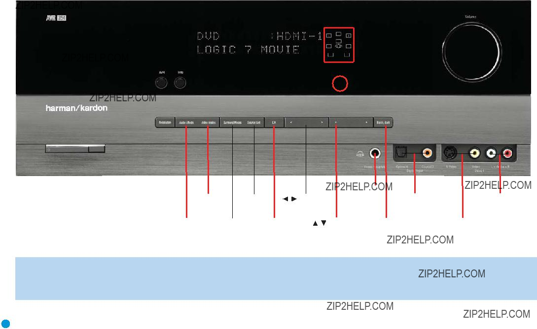
NOTE: To make it easier to follow the instructions throughout the manual that refer to this illustration, a copy of this page may be downloaded from the Product Support section at www.harmankardon.com.
9

AM and FM Antenna Terminals: Connect the included AM and FM antennas to their respective terminals for radio reception.
XM Antenna Jack: Plug in an XM Connect and Play or Mini Tuner antenna module here. The XM antenna module is purchased separately, and should specify that it is for home use with an XM Ready?? product. You will need to subscribe to the XM service, which is available sepa- rately, and activate the service for your antenna module. (XM service
is not available in Alaska and Hawaii.)
Front, Center and Surround Speaker Outputs: Use two- conductor speaker wire to connect each set of terminals to the correct speaker. Remember to observe the correct polarity (positive and negative connections). Always connect the positive lead to the colored terminal on the receiver and the red terminal on the speaker. Connect the negative lead to the black terminal on both the receiver and the speaker. See the Connections section for more information on connecting your speakers.
Surround Back/Zone 2 Speaker Outputs: These speaker outputs are used for the surround back channels in a
As with the other speaker outputs, remember to observe proper polarity by connecting the positive and negative output terminals to the corre- sponding terminals on each speaker.
Subwoofer Output: If you have a powered subwoofer with a
Preamp Outputs: Connect these jacks to an external amplifier if more power is desired.
The Surround Back/Zone 2 Preamp Outputs may be used with an external amplifier to power the surround back channels, or to power the remote zone of a multizone system. Use the
Remote Infrared (IR) Input and Output: When the remote IR receiver on the front panel is blocked, such as when the AVR is placed inside a cabinet, connect an optional IR receiver to the Remote IR Input jack for use with the remote control. The Remote IR Output may be connected to the Remote IR Input of a compatible product to enable remote control through the AVR. This is particularly useful in multizone applications to control a source device from the remote room (when used with the Zone 2 IR Input). When several source devices are used, connect them in ???daisy chain??? fashion.
Zone 2 Infrared (IR) Input: Connect a remote IR receiver located in the remote zone of a multizone system to this jack to control the AVR (and any source devices connected to the Remote IR Output) from the remote zone.
Remote IR Carrier Output: This output is similar in function to the Remote IR Output, with the difference that this jack outputs the full infrared signal as received by the AVR???s IR sensor or the Remote IR
Input, while the Remote IR Output jack outputs a ???stripped??? signal that has no carrier frequency. The full signal may be required by some components with IR inputs. It may also be required when you connect external IR emitters or other devices to the AVR to pass IR signals to other components.
Composite and
NOTE: The Video 2 inputs are associated with a set of outputs. Consider connecting a video recorder here.
Composite and
Composite and
HDMI Inputs and Output: HDMI
If your video display has an HDMI input, make just the HDMI video con- nection to your display; the AVR 354 will automatically transcode analog video signals to the HDMI format, upscaling to as high as 1080p.
Analog 1??? 5: Connect the left and right analog audio outputs of a source device to any of these inputs. These inputs are assignable, which means they may be paired with any video inputs, as explained in subsequent sections of this manual.
NOTES:
???The Analog 3 through 5 connectors physically line up below the Video 1 through 3 (composite and
10
Analog 2
Outputs
Zone 2
Audio
Outputs
NOTE: To make it easier to follow the instructions throughout the manual that refer to this illustration, a copy of this page may be downloaded from the Product Support section at www.harmankardon.com. All connectors are inputs except as indicated.
11

???The Analog 1 and 2 connectors don???t physically line up with any analog video inputs. Consider using them for
???The Analog 2 and 4 inputs are each associated with a set of outputs. Consider using the Analog 2 connectors for an audio recorder, and the Analog 4 connectors for a video recorder (along with the Video 2 connectors).
???You may optionally connect a source to both an analog and digital audio input. This is useful for making recordings, for multizone applications or simply as a backup.
Analog 2 and 4 Outputs: Connect either of these analog audio outputs to the analog audio inputs of a recording device. A signal is available at these outputs whenever an analog audio source is playing. However, the AVR 354 does not convert digital audio sources to analog for recording.
Coaxial 1/2 and Optical 1/2/3 Digital Audio Inputs: If a source has a compatible digital audio output, and if you are not using an HDMI connection for audio for the device, connect it to one of these jacks to hear digital audio formats, such as Dolby Digital, DTS and linear PCM. Use only one type of digital audio connection for each source.
Coaxial Digital Audio Output: If a source is also an audio recorder, connect a coaxial digital audio output to the recorder???s input for improved recording quality. Only PCM digital audio signals are available for recording.
The Bridge II Input: Connect the included Harman Kardon  docking station to this input for use with most docking
iPod models, 4G and later (not included). Make sure the receiver is turned off (in Standby mode) when connecting The Bridge II.
NOTE: When the multichannel player has an onboard digital decoder, it is not necessary to connect it to the
Zone 2 Audio Outputs: Connect these jacks to an external amplifier to power the speakers in the remote zone of a multizone system. When these jacks are used, it is possible to have a full
Component Video 1, 2 and 3 Inputs: If a video source (e.g., DVD player or HDTV tuner) has analog component video (Y/Pb/Pr) capability, and if you are not using an HDMI connection for the device, then connect the component video outputs of the source to one of the sets of component video inputs. Do not make any other video connec- tions to that source.
Component Video Monitor Outputs: If you are using one of the Component Video Inputs and your television or video display is
Output to your display, connect these jacks to the corresponding inputs on your video display.
NOTES:
???Due to
???Composite and
Switched AC Accessory Outlet: You may plug the AC power cord of one source device into this outlet, and it will turn on whenever you turn on the receiver. Do not use a source that consumes more than 50 watts of power.
AC Power Input: After you have made all other connections, plug the AC power cord into this receptacle and into an unswitched wall outlet.

MAIN REMOTE CONTROL FUNCTIONS
The AVR 354 remote is capable of controlling 7 devices, including the AVR itself and an iPod docked in the included The Bridge II. During the installation process, you may program the codes for each of your source components into the remote. Each time you wish to use the codes for any component, first press its Selector button. This changes the button functions to the appropriate codes.
Each Source Selector has been preprogrammed to control certain types of components, with only the codes specific to each brand and model changing, depending on which product code is programmed. The AUX Source Selector may be used for any of five device types: a CD player, an HDTV
on the product code programmed into the AUX Source Selector as described in the Initial Setup section. CD players use codes beginning with a 0, 1 or 2; VCRs use codes beginning with a 3 or 4; HDTV
The remote automatically switches to the correct device mode, and it will operate the device as described in the function list in Table A13 in the appendix.
Similarly, the CBL/SAT Source Selector automatically selects cable or satellite television operation depending on the first digit of the product code: 0, 1 or 2 for cable and 3 or 4 for satellite boxes.
IMPORTANT NOTE: All of the AVR 354???s audio and video inputs are independently assignable. As explained in the Initial Setup section, it is necessary to set up each source, which includes selecting the inputs to which the device is physically connected. Any device may be connected to any compatible input and given any name (e.g., DVD or Game). The Source Selectors??? device types may be changed. For example, the TV Source Selector may be reprogrammed to operate a DVD player.
Most of the buttons on the remote have dedicated functions, although the precise codes transmitted will vary depending on which source device has been selected for operation. Due to the wide variety of functions unique to various source devices, we have included only a few of the most- often used functions on the remote, including alphanumeric keys, transport controls,
Some buttons are only used to operate the AVR, and their functions are available at any time, even if the remote has been switched to another device???s mode: AVR Power On and Off, Audio Effects, Video Modes, Surround Modes, Volume, Mute and Sleep Settings. Press the AVR Settings button near the bottom of the remote to return it to AVR mode.
Any given button may have different functions, depending on which component is being controlled. Some buttons are labeled with these functions. For example, the Page Up/Down Buttons are labeled for use as Channel Up/Down Buttons when controlling a television or cable box. See Table A13 in the appendix for listings of the different functions for each type of component.
IR Transmitter Lens: As buttons are pressed on the remote, infrared codes are emitted through this lens. Make sure it is pointing toward the component being operated.
AVR Power On Button: Press this button to turn on the AVR. The Master Power Switch on the AVR 354???s front panel must first have been switched on.
Device Power Off Button: When the remote has been switched to a device???s mode by pressing its Source Selector, press this button to turn off the device.
Device Power On Button: When the remote has been switched to a device???s mode by pressing its Source Selector, press this button to turn on the device.
Mute Button: Press this button to mute the AVR 354???s speaker and headphone outputs temporarily. To end the muting, press this button or adjust the volume. Muting is also canceled when the receiver is turned off.
AVR Power Off Button: Press this button to turn off the AVR 354.
Source Selectors: Press one of these buttons to select a source device, which is a component where a playback signal originates, e.g., DVD, CD, cable TV, satellite or HDTV tuner. This will also turn on the receiver and switch the remote???s mode to operate the source device. The first press of the Radio Selector switches the AVR to the
Audio Effects: This button is only used to operate the AVR. Press it to directly access the Audio Effects submenu, which allows adjustment of the tone and other controls. Each successive press scrolls to the next line in the menu. See the Initial Setup section for more information.
Video Modes: This button is only used to operate the AVR. Press it for direct access to the Video Modes submenu, which contains settings that may be used to improve the picture if necessary after you have adjusted the picture settings using the video display or TV. Each succes- sive press scrolls to the next line in the menu. See the Advanced Functions section for more information.
Surround Modes: This button is only used to operate the AVR. Press it to directly access the Surround Modes submenu. Each successive press scrolls to the next line in the menu, or use the ???/?? Buttons
to scroll to the next line: Auto Select, Virtual Surround, Stereo, Movie, Music or Video Game. Each menu line represents a type of audio signal, and is set to the preferred surround mode that you manually select.
Press the OK Button when the menu line is highlighted, and the avail- able surround mode options for the current signal will appear. Use the ???/?? Buttons to select the desired mode, and press the OK Button to engage it. Press the Back/Exit Button to exit the Surround Modes menu and display the next higher menu in the hierarchy.
See the Advanced Functions section for more information on surround modes.
Sleep Settings Button: Press this button to activate the sleep timer, which turns off the receiver after a programmed period of time of up to 90 minutes. Each successive press increases the timer by 10 minutes, ending with the ???Sleep Off??? message.

MAIN REMOTE CONTROL FUNCTIONS
Volume Control: Press this button to raise or lower the volume.
Navigation (???/??/??? / ??? ) and OK Buttons: These buttons are used to make selections within the menu system. These buttons are also used to operate the tuner.
Alphanumeric Keys: Use these buttons to enter numbers for
radio station frequencies or to select station presets. Use the alphabetic keys with other products as required. When prompted for a text entry, the first press of the key displays the first letter printed above the key. Each additional press displays the other letters. When the desired letter appears, wait a moment for it to be entered before moving to the next character.
Last Channel: When controlling a cable, satellite or HDTV
Activity: This button may be programmed to transmit a series of commands with a single press, which is useful for powering on all devices and selecting the correct settings on each device, or for selecting
Back/Exit: Press this button to return to the previous menu or to exit the menu system. This button may have the same effect with some source devices.
Menu Button: This button is used to display the main menu on some source devices. To display the AVR 354???s main menu, press the AVR Settings Button.
Disc Menu: While a DVD is playing, press the DVD Source Selector, then this button, to display the disc???s menu.
Teletext Buttons: Use these buttons with a
Channel/Page Control: When the tuner has been selected, this control selects a preset radio station. Press these buttons while operat- ing a cable, satellite or HDTV
Record Button: Use this button to make recordings when an audio or video recorder is in use.
AVR Settings Button: Press this button to display the AVR???s Main Menu. It is also used to switch the remote???s device mode from a source device to the AVR.
Info Settings Button: Press this button to display the AVR???s Info Menu, which contains the settings for the current source.
Source Settings Button: Press a Source Selector and then this button to display a source device???s settings menu.
Zone Selector: Use this switch to select whether AVR commands will affect the main listening area (Zone 1) or the remote zone of a multizone system (Zone 2). For normal operation, leave the switch in the Zone 1 position.
Track Skip: These buttons have no effect on the receiver, but are used with source components to change tracks or chapters.
Transport Controls: These buttons have no effect on the receiver, but are used to control many source components.
Light: Press this button to illuminate the buttons on the remote. Press it again to turn the backlight off, or wait ten seconds after the last button press for the light to turn off on its own.
Learn: The AVR 354 remote is capable of ???learning??? individual IR codes from the original remote that came with your TV or a device that is connected to any of the source inputs. See Step Eight of the Installation section for instructions on learning remote codes.

IR Transmitter Lens
AVR Power Off
AVR Power On
Source Selectors
Audio Effects
Alphanumeric Keys
Last
Back/Exit
Light
Teletext
Volume
Mute
Record
Info Settings
AVR Settings
Zone Selector
Learn
Device Power On
Device Power Off
Video Modes
Surround Modes
Activity
Menu


 Navigation
OK
Disc Menu
Channel
Transport Controls
Source Settings
Sleep Settings
NOTE: To make it easier to follow the instructions throughout the manual that refer to this illustration, a copy of this page may be downloaded from the Product Support section at www.harmankardon.com.

ZONE 2 REMOTE CONTROL FUNCTIONS
The Zone 2 remote is a simplified device for use in the remote room of a multiroom system with an IR receiver connected to the Multiroom IR Input. It may be used to control the power, volume and mute functions for the remote zone; select a source input for the remote zone and con- trol a compatible Harman Kardon DVD, CD or tape player that is con- nected to one of the AVR???s Remote IR Outputs.
The Zone 2 remote may also be used in the main listening room to directly control the AVR 354 and Harman Kardon DVD, CD or tape players. In that case the power, volume and mute controls will affect only the main listening area.
The Zone 2 remote requires two AAA batteries (included) that are installed in the battery compartment on the back of the remote. Gently pull down on the tab at the top of the battery compartment cover and pull the cover off the remote. Make sure to observe proper polarity by matching the + and ??? symbols on the remote to the corresponding symbols printed inside the compartment.
IR Transmitter: This
Power Off: Press this button to turn off the AVR 354. The Zone 2 remote has no Power On Button, since the AVR turns on its multiroom system automatically when any of the Input Selectors is pressed, even if the AVR itself is in Standby mode. When in the main listening room, press any Input Selector or the AVR Selector to turn on the AVR 354, as you would when using the main system remote.
Mute: Press this button to mute the AVR 354???s remote zone speakers temporarily. To end the muting, press this button or adjust the volume, or turn off the multiroom system. Unless the remote is used in the main listening area, only the remote zone will be affected.
Source Selectors: Press one of these buttons to select a source device for the remote zone. It will also turn on the multiroom system and switch the remote to operate the source device. You may select a different source device than is in use in the main room. If you select the same source as the main room, then any commands sent to the source, such as changing radio stations or skipping tracks on a CD, will affect both zones. The first press of the Radio Selector switches the AVR to the
NOTE: The blank button to the left of the Radio Selector is not used, even though pressing it causes the Zone Indicator to light up.
Transport Controls: These buttons have no effect on the receiver, but are used to control many source components.
AVR Settings Button: Press this button to display the AVR???s Main Menu. It is also used to switch the remote???s device mode from a source device to the AVR.
Info Settings Button: Press this button to display the AVR???s Info Menu, which contains the settings for the current source.
Sleep Settings Button: Press this button to activate the sleep timer, which turns off the receiver after a programmed period of time of up to 90 minutes. Each successive press increases the timer by 10 minutes, ending with the ???Sleep Off??? message.
Back/Exit: Press this button to return to the previous menu or to exit the menu system. This button may have the same effect with some source devices.
Menu Button: This button is used to display the main menu on some source devices. To display the AVR 354???s main menu, press the AVR Settings Button.
Navigation (???/??/??? / ??? ) and OK Buttons: These buttons are used to make selections within the menu system. These buttons are also used to operate the tuner.
Zone Selector and Zone Indicator: Each press of the Zone Selector determines whether the AVR commands will affect the main listening area (Zone 1) or the remote zone (Zone 2). The Zone Indicator will turn green when Zone 1 has been selected, and red for Zone 2. The Zone Indicator will also light briefly whenever any button is pressed.
Volume Controls: Press these buttons to raise or lower the volume in the remote zone.

Power Off
Not Used
AVR Settings
Back/Exit
Volume Controls
Zone Selector
Cable/Sat DVD TheBridge
Radio
Game MediaServer
OK
 VOLUME
Select 


Zone ll.4
IR Transmitter
Mute
Source Selectors
Sleep Settings
Info Settings
Menu


 Navigation
OK
Transport Controls
Zone Indicator
NOTE: To make it easier to follow the instructions throughout the manual that refer to this illustration, a copy of this page may be downloaded from the Product Support section at www.harmankardon.com.
17

INTRODUCTION TO HOME THEATER
The AVR 354 may be the first multichannel surround sound receiver you have owned. Although it has more connections and features than
If you are already familiar with home theater, you may skip this section and proceed to the Connections section on page 19.
Typical Home Theater System
A home theater typically includes an audio/video receiver, which controls the system; a DVD player; a source component for television broadcasts, which may be a cable box, a satellite dish receiver, an HDTV tuner or simply an antenna connected to the TV; a video display (television);
and loudspeakers.
All of these components are connected using various types of cables for audio and video signals.
Multichannel Audio
The main benefit of a home theater system is that several loudspeakers are used in various locations around the room to produce ???surround sound.??? Surround sound immerses you in the musical or film presentation for increased realism.
The AVR 354 may have up to seven speakers connected directly to it (plus a subwoofer). Each main speaker is powered by its own amplifier channel inside the receiver. When more than two speakers are used, it is called a multichannel system.
???Front Left and Right ??? The main speakers are used the same way as in a
???Center ??? The center speaker is usually placed above or below the video screen, and is used mostly for dialogue in movies and television programs. This placement allows the dialogue to originate near the actors??? faces, for a more natural sound.
???Surround Left and Right ??? The surround speakers are used to improve directionality of ambient sounds. In addition, by using more loudspeakers in the system, more dynamic soundtracks may be played without risk of overloading any one speaker.
???Surround Back Left and Right ??? Additional surround speakers may be placed behind the listening position, improving the precision with which ambient sounds may be placed and allowing for more
The surround back speakers may also be used with specialized surround modes that are designed for use with
Audio and Logic 7 (7.1 modes). However, the surround back speakers
18
are optional. In fact, the AVR 354 enables you to set up a
Many people expect the surround speakers to play as loudly as the front speakers. Although all of the speakers in the system will be calibrated to sound equally loud at the listening position, most artists use the surround speakers for ambient effects only, and they program their materials to steer very little sound to these speakers.
???Subwoofer ??? A subwoofer is a
Surround Modes
There are different theories as to the best way to present surround sound and to distribute soundtrack information among the various speakers. A variety of algorithms have been developed in an effort to accurately reproduce the way we hear sounds in the real world. The result is a rich variety of surround mode options. Some modes are selected automatically, depending on the signal being received from the source. In many cases, you may select a surround mode manually.
Several companies have taken surround sound in slightly differing directions. It is helpful to group the numerous surround modes:
???Dolby Laboratories Modes ??? Dolby TrueHD, Dolby Digital Plus, Dolby Digital, Dolby Digital EX, Dolby Pro Logic II and IIx, Dolby Virtual Speaker, Dolby Headphone
???DTS Modes ???
???Harman International (the Harman Kardon parent company) Modes ??? Logic 7
???Stereo Modes ??? Generic modes that expand upon conventional
Table A12 in the appendix contains detailed explanations of the differences between the various mode groups, and the mode options available within each group. Digital modes, such as Dolby Digital and DTS, are only available with specially encoded programs, such as HDTV, DVDs and digital cable or satellite television. Other modes may be used with various digital and analog signals to create a different surround presentation, or to use a different number of speakers. Surround mode selection depends upon the number of speakers in your system, the materials you are watching or listening to, and your personal tastes. Feel free to experiment.
18

CONNECTIONS
There are different types of audio and video connections used to connect the receiver to the speakers and video display, and to connect the source devices to the receiver. To make it easier to keep them all straight, the Consumer Electronics Association has established the CEA??
Table 1 ??? Connection Color Guide
Audio Connections
Digital Audio Connections
Coaxial
OpticalInput
Video Connections
HDMI??? Connections (digital audio/video)
HDMI
Types of Connections
This section will briefly review different types of cables and connections.
Speaker Connections
Speaker cables carry an amplified signal from the receiver???s speaker terminals to each loudspeaker. Speaker cables contain two wire conduc- tors, or leads, inside plastic insulation. The two conductors are usually differentiated in some way, by using different colors, or stripes, or by adding a ridge to the insulation. Sometimes the wires are different, colors e.g.
The differentiation is important because each speaker must be connected to the receiver???s
(+) and one negative
Always connect the positive terminal on the loudspeaker, which is usually colored red, to the positive terminal on the receiver, which is colored as shown in the Connection Color Guide (Table 1). Similarly, always connect the black negative terminal on the speaker to the black negative terminal on the receiver.
Figure 1 ???
Bare wire cables are installed as follows (see Figure 2):
1.Unscrew the terminal cap until the
2.Insert the bare end of the wire into the hole.
3.
Figure 2 ???
Subwoofer
The subwoofer is a specialized type of loudspeaker used to play only the low frequencies (bass), which require much more power than the other speaker channels. In order to obtain the best results, most speaker manufacturers offer powered subwoofers, in which the speaker contains its own amplifier on board. Usually, a
Although the subwoofer output looks similar to the analog audio jacks used for the various components, it is filtered and only allows the low frequencies to pass. Don???t connect this output to any other devices.
Although doing so won???t cause any harm, performance will suffer.
Preout Subwoofer
Figure 3 ??? Subwoofer
Connecting Source Devices to the AVR
The AVR 354 is designed to process audio and video input signals, playing back the audio and displaying the video on a television or monitor connected to the AVR. These signals originate in what are known as ???source devices,??? including your DVD player, CD player, DVR (digital video recorder) or other recorder, tape deck, game console, cable or satellite television box or MP3 player. Although the tuner is built into the AVR, it also counts as a source, even though no external connections are needed, other than the FM and AM antennas and the XM antenna module.
Separate connections are required for the audio and video portions of the signal, except for digital HDMI connections. The types of connections used depend upon what???s available on the source device, and for video signals, the capabilities of your video display.
19

CONNECTIONS
Audio Connections
There are two formats for audio connections: digital and analog. Digital audio signals are required for listening to sources encoded with digital surround modes, such as Dolby Digital and DTS, or for
NOTE: Since HDMI signals may carry both audio and video, if your video display device has an HDMI input, make a single HDMI connection from your source device (such as a DVD player) to the AVR. No separate digital audio connection is usually required. Make sure to turn the volume on your television all the way down.
Digital Audio
The AVR 354 is equipped with three HDMI
There are different HDMI versions, depending on the capability of the source device and the type of signal it is capable of transmitting.
In addition, receivers and processors such as the AVR 354 may handle the incoming signal in several different ways, depending on their capability as well. The AVR 354 uses HDMI version 1.3a, and is capable of processing both the audio and video components of the HDMI data, minimizing the number of cable connections in your system. Thanks to the higher bandwidth and speed of HDMI version 1.3a, the AVR 354 implements Deep Color, which increases by an order of magnitude the shades of color that can be displayed; and the latest lossless multichannel audio formats, including Dolby TrueHD and
NOTE: Some
In addition, the AVR 354 will convert analog video signals to the HDMI format, upscaling to
If your video display or source device is not
Coaxial digital audio jacks are usually
Figure 5 ??? Coaxial Digital Audio
Optical digital audio connectors are normally covered by a shutter to protect them from dust. The shutter opens as the cable is inserted. Input connectors are
Optical
Optical digital audio cable
Figure 6 ??? Optical Digital Audio
Analog Audio
Analog connections require two cables, one for the left channel (white) and one for the right channel (red). These two cables are often attached to each other for most of their length. See Figure 7.
Most sources that have digital audio jacks also have analog audio jacks, although some older types of sources, such as tape decks, only have analog jacks. For sources that are capable of both digital and analog audio, you may make both connections.
The analog audio connection is strongly recommended if you intend to use the source with the multizone system. It???s required if you will be using the multizone preamp outputs with an external amplifier to power your remote speakers, as the AVR 354???s multizone system is not capa- ble of converting the digital signal to analog format. It???s suggested that you also use the analog audio connections when using the Surround Back/Zone 2 speaker outputs, in case another
You may only record materials from DVDs or other
The physical HDMI connection is simple. The connector is shaped for easy
Analog audio
L
to connect it to the AVR???s HDMI Output, but a separate audio connection is required. HDMI cable runs are usually limited to about 10 feet, depending on the type of cable used.
Figure 4 ??? HDMI Connection
Figure 7 ??? Analog Audio
Multichannel analog connections are used with some
required for
Front Surround Center
Multichannel analog audio cable (RCA)
Subwoofer
Figure 8 ??? Multichannel Analog Audio
Harman Kardon receivers also include a proprietary, dedicated audio connection called The Bridge II. If you own a docking iPod (most models, 4G or later), connect The Bridge II (included) to The Bridge II port on the receiver. See Figure 9. Dock your iPod (not included) in The Bridge II, and you may listen to your audio materials through your
Figure 9 ??? The Bridge II
Video Connections
Although some sources only produce an audio signal (e.g., CD player, tape deck), many sources output both audio and video signals (e.g., DVD player, cable television box, HDTV tuner, satellite box, VCR, DVR). In addition to the audio connection, make one type of video connection for each of these sources (only one at a time for any source).
Digital Video
If you have already connected a source device to one of the HDMI inputs as explained in the Digital Audio Connections section, you have automatically made a video connection at the same time, as the HDMI signal includes both digital audio and video components.
If the source device is not capable of transmitting its digital audio signal through the HDMI connection, use one of the coaxial or optical digital audio inputs for the source.
If a multichannel analog audio connection is required for certain lossless formats (e.g.,
CONNECTIONS
Analog Video
There are three types of analog video connections: composite video,
Composite video is the basic connection most commonly available. The jack is usually
Composite video cable
Figure 10 ??? Composite Video
Figure 11 ???
Component video separates the video signal into three components ??? one luminance (???Y???) and two
Component video cable
Figure 12 ??? Component Video
If it???s available on your video display, an HDMI connection is recom- mended as the best quality connection, followed by component video,
NOTES:
???
???Standard and
Antennas
The AVR 354 uses separate terminals for the included FM and AM antennas that provide proper reception for the tuner.

CONNECTIONS
The FM antenna uses a
Figure 13 ??? FM Antenna
The AM loop antenna needs to be assembled. Connect the two leads to the spring terminals on the receiver. As AM antenna leads have no polarity, it doesn???t matter which of the two terminals is used for either lead. See Figure 14.
Figure 14 ??? AM Antenna
To enjoy XM satellite radio, purchase an XM antenna module designed for use with XM Ready devices and a subscription to the XM service. We recommend the XM Mini Tuner and Home Dock Bundle, available at www.xmradio.com. The older Connect and Play module is also com- patible with the AVR 354, but it may no longer be available in your area.
An XM
The
22

SPEAKER PLACEMENT
Before you begin to connect cables, it is important to place your speakers in their correct locations in the room.
Optimally, the speakers should be placed in a circle with the listening position at its center. The distance from the listening position to the video display forms the radius of the circle.
The speakers should be angled so that they directly face the listening position.
Placement of Surround Speakers in a
System
The side surround speakers should be placed 110 degrees from the center speaker, that is, slightly behind and angled toward the listener. If this isn???t feasible, place them behind the listener, with each surround speaker facing the
Front Speaker Placement
The center speaker is placed either on top of, below or mounted on the wall above or below the video display screen.
The front left and right speakers are placed along the circle, about 30 degrees from the center speaker and angled toward the listener.
It is best to place the front left/right and center speakers as close to the same height as possible, preferably at about the same height as the listener???s ears. In any event, the center speaker should be no more than two feet above or below the left/right speakers.
Placement of the surround speakers depends on the number of speakers in your system. If you???re using only two speakers with the AVR 354, place them in the front left and right positions, and skip to the Installation section. However, we recommend using the AVR 354 in a 5.1- or
SL  SR
SR
Figure 15 ??? Speaker Placement
Placement of Surround Speakers in a
System
In a
Figure 16 ??? Speaker Placement
NOTE: Some speaker manufacturers offer
a
If you wish to use the AVR 354 with a
23

SPEAKER PLACEMENT
Subwoofer Placement
The subwoofer???s location is less critical, since
In some installations it may be desirable to use two subwoofers for a
NOTE: Your receiver will sound its best when the same model loudspeaker is used for all positions (other than the subwoofer). If that isn???t possible, try to use speakers made by the same manufacturer.

You are now ready to connect the various components to the receiver. Before beginning, turn off all components, including the AVR 354, and unplug their power cords. Don???t plug in any of the power cords until you have finished making all of your connections.
Remember that the receiver generates heat while it is on. Select a location that leaves several inches of space on all sides of the receiver. Avoid completely enclosing the receiver inside an unventilated cabinet. It is preferable to place components on separate shelves rather than stacking them directly on top of the receiver. Some surface finishes are delicate. Try to select a location with a sturdy surface finish.
Step One ??? Connect the Speakers
If you have not yet done so, place your speakers in the listening room, as described in the Speaker Placement section above.
Connect the center, front left, front right, surround left, surround right, surround back left and surround back right loudspeakers to the corresponding speaker terminals on the AVR 354. See Figure 17. Maintain the proper polarity by always connecting the positive and negative terminals on each speaker to the positive and negative terminals on the receiver. Use the Connection Color Guide on page 19 as a reference.
C
AVR 354
Figure 17 ??? Speaker Connections
NOTE: If you only have one surround back speaker, wait until after you have run the EzSet/EQ process in the Initial Setup section before connecting it to the Surround Back Left speaker outputs.
Step Two ??? Connect the Subwoofer
Connect the Subwoofer Output on the AVR 354 to the
When the system has two subwoofers for a
INSTALLATION
AVR 354
SUB
Figure 18 ??? Subwoofer Connection
Step Three ??? Connect the Antennas
Connect the FM and AM antennas to their terminals. If you have purchased an XM antenna module designed for connection to an XM Ready device, connect it now. To enjoy XM Radio, remember to purchase a subscription and activate your antenna module. More information is available at www.xmradio.com. See Figure 19.
AVR 354
AM
FM
Figure 19 ??? Antenna Connections
Step Four ??? Connect the Source Components
A source is a device where the audio and video signals originate. Some sources, such as CD players, only offer audio, while sources used for watching movies or
Referring to the photograph of the AVR 354 remote control on page 15, there is a section of 8 buttons near the top of the remote designated ???Source Selectors???: Cable/Sat, DVD, Media Server, Radio, TV, Game, The Bridge and AUX. Each of these buttons corresponds to a ???source input???. The AVR 354???s flexible design allows you to use almost any combination of audio and video connections for each source device. The goal of Step Four of the Installation is to match up each of your source devices, e.g., DVD player and cable television box, with the correct connectors on the AVR 354.
NOTE: This is not true of The Bridge II and the tuner, which use dedicated audio source signals, and a dedicated video signal when applicable for The Bridge II.
You may connect a source device to any appropriate input connectors. Note which audio and video inputs are used for each device in Table A5 in the appendix. Table A2 indicates the default
25

INSTALLATION
The precise connections to be made depend on the capabilities of the source device and your video display (TV). Select the best audio and video connections for each source. The types of connections are listed in order of preference:
HDMI Connections
???Choose the HDMI connection if it???s available on your source device and your TV. An HDMI connection carries both digital audio and video, enabling a
are required.
NOTE: If your
Audio Connections (for
???Choose one digital audio connection: Optical or Coaxial
???Optional, or where digital audio is not available: Analog audio for making recordings for personal use or as a backup. Analog audio is required for older analog sources that don???t have digital audio outputs, such as cassette decks.
Video Connections (for
(choose only one, and make sure that type is available on your TV)
NOTES:
???If the video display is equipped with a DVI digital video input, make sure it is also
???If the source or video display has a DVI input, use an HDMI-
Connect a DVD, SACD,
HDMI Video: If the DVD player and the TV both have an HDMI connector, connect the player as follows (see Figure 20):
???Connect the DVD player???s HDMI output to the HDMI 1, 2 or 3 Input on the AVR.
AVR 354
Figure 20 ??? Connecting an
If the player is capable of playing multichannel discs, including DVD- Audio, SACD,
???Connect the DVD player???s
AVR 354
Figure 21 ??? Connecting a Multichannel Audio Player
Component Video: If the DVD player or the TV does not have an HDMI connector, but they both have component video connectors, connect the player as follows (see Figure 22):
???Connect the DVD player???s component video output to the Component Video 1, 2 or 3 Input on the AVR.
???Connect one of the DVD player???s digital audio outputs to one of the Coaxial or Optical inputs on the AVR.
AVR 354
Figure 22 ??? Connecting a
If the player is capable of playing multichannel discs, including
???Connect the DVD player???s

???Connect the DVD player???s
???Connect the DVD player???s digital audio output to one of the Coaxial or Optical inputs on the AVR.
If the player is capable of playing multichannel discs, including
???Connect the DVD player???s
AVR 354
Figure 23 ??? Connecting a Composite- or
NOTES:
???Refer to Table A2 in the appendix for the default audio and video input assignments for each source. Using the default connections, if appropriate for your system, may save a few steps during Initial Setup. However, thanks to the AVR 354???s flexibility, you may assign any audio and any video input to any source, as long as the assignments match the physical connections.
???If you wish to make recordings from a DVD, use an
Connect an Audio/Video Recorder (PVD, DVR or TiVo)
HDMI Video: If the recorder and the TV both have an HDMI connector, connect the recorder as follows (see Figure 24):
???Connect the recorder???s HDMI output to the HDMI 1, 2 or 3 Input on the AVR. This connection is for playback only, as the AVR cannot make recordings from HDMI sources.
???To make recordings, follow the instructions below for Composite/
INSTALLATION
AVR 354
Figure 24 ??? Connecting an
Component Video: If the recorder or the TV does not have an HDMI connector, but they both have component video connectors, connect the recorder as follows (see Figure 25):
???Connect the recorder???s component video output to the Component Video 1, 2 or 3 Input on the AVR. This connection is for playback only, as the AVR cannot make recordings from component video sources.
???Connect the recorder???s digital audio output to a Coaxial or Optical Input on the AVR (if available).
???Follow the instructions in the
AVR 354
Figure 25 ??? Connecting a
???Connect the recorder???s
???Connect the recorder???s
???Connect the recorder???s analog audio outputs to the Analog 4 Audio Inputs on the AVR.
???Connect the recorder???s analog audio inputs to the Analog 4 Audio Outputs on the AVR.
27

INSTALLATION
Figure 26 ??? Connecting a Composite or
???To make
Connect a Cable TV, Satellite, HDTV or Other
NOTE: If the TV has a digital audio output, connect it to one of the digital audio inputs. If you use a direct cable connection to your TV, or an antenna connection with the TV???s internal tuner, connect either the TV???s digital audio output (if available) or its analog audio outputs to the AVR. See Step Five for information on connecting the receiver???s video monitor outputs to the television.
HDMI Video: If the
???Connect the
Component Video: If the
???Connect the
???Connect the
Composite S/Video: If the best video connection common to both the
???Connect the
???Connect the
Figure 27 ??? Connecting a Composite- or
Connect a CD Player or Any
If the CD player or other component has a digital audio output, connect it to any available digital audio input on the AVR. If not, connect the CD player???s left and right analog audio outputs to the Analog 1 or 2 Audio Inputs. No video connection is required, although the AVR will display any signal at the video input assigned to the same source as the audio inputs. See Figure 28.
AVR 354
Figure 28 ??? Connecting a CD or
NOTES:
???A turntable may only be connected to the AVR if it is equipped with an internal phono preamp, or if you supply an external phono preamp, available at some audio specialty stores or through the Harman Kardon Parts Dept. You may then connect it to any set of analog audio inputs.
???Although there is no official source on the AVR 354 named CD, Phono or Audio, you may assign the audio device to an available source, such as TV (if the Cable/Sat source is in use for broadcast television), Game or AUX. See the Initial Setup section for more details on source assignment.
Connect a Tape Deck or Any
If the recorder has digital audio inputs and outputs, connect either its coaxial or optical digital audio output (not both) to the corresponding available input on the AVR, and connect the AVR???s Coaxial Digital Audio Output to the recorder???s coaxial digital audio input.

To make analog audio recordings, connect the recorder???s left and right analog audio outputs to the Analog 2 Audio Inputs on the AVR, and the recorder???s analog audio inputs to the AVR???s Analog 2 Audio Outputs.
No video connection is required, although the AVR will display any signal at the video input assigned to the same source as the Analog 2 Audio Inputs. See Figure 29.
AVR 354
Figure 29 ??? Connecting an Audio Recorder
INSTALLATION
Connecting a Game Console, Camera or Other Device
If a device will only be connected temporarily, you may use the audio/ video inputs on the front panel. When not in use, place the supplied covers over the jacks for a cleaner appearance by snapping the covers in place. To remove the covers, gently press on the left side of each cover so that it pivots out.
Video Components: Install video components, e.g., game consoles and camcorders, as follows (see Figure 31):
???Connect the component???s
???Connect the component???s optical or coaxial digital audio output to either the Optical or Coaxial Input on the front panel (if available). For fully analog devices, connect the device???s analog audio outputs to the AVR???s
Connect an iPod Using Docking Station
The AVR 354 includes The Bridge II, a docking station compatible with most docking iPod models, 4G and later (not included). Enjoy audio and video content stored on the iPod, with all the power and fidelity of your home theater system. With The Bridge II, navigation and control of the iPod is a simple matter of using the preprogrammed AVR remote and following the
Simply plug the proprietary cable from The Bridge II into the special The Bridge II connector on the rear of the AVR 354. See Figure 30. Use the dock adapter supplied with the iPod, or obtain an adapter to avoid damaging The Bridge II or the Apple iPod during use.
AVR 354
Figure 30 ??? The Bridge II Connector
NOTE: The original version of this accessory, known as
The Bridge, is not compatible with the AVR 354. Should you misplace The Bridge II that is included with the AVR 354 in the future, contact Harman Kardon and make sure to order The Bridge II as a replacement.
Alternatively, or if you have another brand of portable audio player, use an interconnect with a stereo
AVR 354
Figure 31 ??? Connecting a Device to the
Audio Components: Connect
NOTE: If your video devices are equipped with HDMI or com- ponent video outputs, you may connect them to any available audio and video input on the AVR.
Step Five ??? Connect the Video Display
IMPORTANT NOTE: Do not connect any video output on the video display (TV) to any video input on the AVR. Doing so will cause undesirable video interference.
HDMI Video: If the display has an HDMI input, connect the HDMI Monitor Output to the display (see Figure 32). Thanks to the AVR 354???s sophisticated video processing and upscaling capabilities, no other video connections are required from the AVR to the video display. Analog video sources (composite,
29

INSTALLATION
AVR 354
Figure 32 ??? HDMI Monitor Output
Component Video: If the display does not have HDMI inputs, but does have component video inputs, connect the Component Video Monitor Outputs to the display (see Figure 33). As with HDMI connec- tions, the AVR 354 is capable of converting composite and
AVR 354
Figure 33 ??? Component Video Monitor Outputs
AVR 354
Figure 34 ??? Composite and
Consult the manual for your TV to make sure you understand how to select the correct video input.
Step Six ??? Plug in AC Power
Having made all of your wiring connections, it is now time to plug each component???s AC power cord into a working outlet.
You may plug one device into the AC Switched Accessory Outlet on the rear of the AVR 354. See Figure 35. Make sure this device draws no more than 50 watts. The device should have its mechanical or master power switch turned on, and it will power on any time the AVR 354 is turned on. If the device has a clock or must always be on, do not plug it into this outlet.
AVR 354
Figure 35 ??? Switched AC Accessory Outlet
Before plugging the AVR 354???s AC Power Cord into an electrical outlet, make sure that the Master Power Switch on the front panel is popped out so that the word OFF appears on its top. Gently press the button to turn the switch off. This will prevent the possibility of damaging the AVR in case of a transient power surge.
The AVR 354 is equipped with a detachable power cord. It allows you to fully wire your system before installing the AVR, which may be required for some
AVR 354
Figure 36 ??? AC Power Input
Step Seven ??? Insert Batteries in Remote
The AVR 354 remote control uses four AAA batteries, which are included.
To remove the battery cover located on the back of the remote, squeeze the tab and lift the cover.
Insert the batteries, as shown in Figure 37, making sure to observe the correct polarity.
Figure 37 ??? Remote Battery Compartment
When using the remote, remember to point the lens toward the front panel of the AVR 354. Make sure no objects, such as furniture, are blocking the remote???s path to the receiver. Bright lights, fluorescent lights and plasma video displays may interfere with the remote???s functioning. The remote has a range of about 20 feet, depending on the lighting conditions. It may be used at an angle of up to 30 degrees to either side of the AVR.
If the remote lights up when a button is pressed but the AVR does not respond, check that the Zone Selector Switch at the bottom is in the Zone 1 position.
If the remote seems to operate intermittently, or if pressing a button on the remote does not cause the AVR Settings Button or one of the Source Selectors to light up, then make sure the batteries have been inserted correctly, or replace all three batteries with fresh ones.
Step Eight ??? Program Sources Into the Remote
The AVR 354 remote not only is capable of controlling the receiver, but it may also be programmed to control many brands and models of DVD players, cable boxes, satellite receivers, the Harman Kardon DMC 1000 digital media center and TVs. It is also preprogrammed to operate your iPod when docked in The Bridge II.
It may help to think of the remote as a book with pages. Each ???page??? represents the button functions for a different device. To access the functions for a particular device, first turn to its page; that is, switch the remote???s device mode. Press the AVR Settings Button to access the codes that control the receiver, or the Source Selector Buttons
to access the codes for the devices programmed into the remote.
The AVR 354???s remote control is
1.Using the codes in Tables A14 ??? A24 of the Appendix, look up the product type (e.g., DVD, cable TV box) and the brand name of your source. The number(s) listed is/are potential candidates for the correct code set for your particular device.
NOTE: The AUX Source Selector is used for the CD, HDTV, PVD recorder, TiVo and VCR device types. Select the brand code from the appendix table corresponding to the device and pro- gram it into the AUX Source Selector. Similarly, the CBL/SAT Source Selector is used for either a cable or satellite TV
INSTALLATION
2.Turn on your source device.
3.This step places the remote in program mode. Referring to Figure 38, press and hold the Source Selector. The button will turn red, then go dark. Continue holding it, and when it turns red again, release the button; the remote is now in program mode. Follow the directions in Step 4, below.
Figure 38 ??? Source Selectors
Optional: To reassign a device type from one Source Selector to another Source Selector not being used (e.g., if there are two DVD players in the system), press the Source Selector for the new device type now. For example, to reassign the Cable/Sat Source Selector to operate a DVD player, first press and hold the Cable/Sat Button, and then press the DVD Button.
4.Enter a code from Step 1, above.
a)If the device turns off, press the Source Selector again to accept the code; it will flash. The remote will exit Program mode.
b)If the device does not turn off, try entering another code. If you run out of codes, you may search through all of the codes in the remote???s library for that product type by pressing the ??? or ?? Button repeatedly until the device turns off. When the device turns off, enter the code by pressing the Source Selector, which will flash. The remote then exits Program mode.
5.Once you have programmed a code, it???s a good idea to try using some other functions to control the device. Sometimes, manufacturers use the same Power code for several different models, while other codes will vary. You may wish to repeat this process until you???ve programmed a satisfactory code set that operates most of the functions you frequently use.
6.Find out which code number you have programmed by pressing and holding the Source Selector to enter the Program mode. Then press the OK Button, and the Source Selector will flash in the code sequence. One flash represents ???1???, two flashes for ???2???, and so forth. A series of many fast flashes represents ???0???. Record the codes programmed for each device in Table A9 in the appendix.
After you have programmed a code set to operate a device, test the functions to see which ones may be missing or not operating correctly. You may ???learn??? individual key codes if you have the device???s original remote control by following this procedure:
31

INSTALLATION
a)Place the two remotes so that their IR transmitters face each other end to end, separated by about one inch. See Figure 39. The AVR 354 remote???s transmitter also serves as an IR receiver during the learning process.
Step Nine ??? Remote IR Inputs and Output (Optional)
The AVR 354 is equipped with a Remote IR Input, a Zone 2 Input and both
Figure 39 ??? AVR 354 and Original Remote
b)Press the Source Selector for the device mode you wish to learn a code into, and place the AVR 354 remote in Learning mode by
pressing and holding the Learn Button until the Source Selector lights up, then release. See Figure 40.
Figure 40 ??? Learning Remote Commands
c)Press the button on the AVR 350 remote you wish to program with the new code, and the Source Selector will flash once. You may learn a new code into the following buttons: Device Power On/Off,
Alphanumeric Keys, Last Button, Back/Exit Button, Menu Button, ???/??/??? / ??? Navigation Buttons, OK Button, Disc Menu Button, the four Teletext Buttons, Channel Up/Down, Volume Up/Down, Mute and the Transport Controls (including Record).
d)Press and hold the button on the device???s original remote whose code you wish to ???learn??? until the Source Selector flashes three times, then release.
e)You may program additional buttons by repeating steps c) and d). Press the Learn Button once to exit Learning mode, or wait for the remote to ???time out??? and exit Learning mode on its own after about 30 seconds.
If you are unable to locate a code set that correctly operates your source device, it will not be possible to use the AVR remote to control that device. However, you may still connect the source to the AVR 354 and operate it using the device???s original remote control.
Most of the button labels on the remote describe the button???s function when used to control the AVR 354. However, the button may perform a very different function when used to control another device. Refer to the Remote Control Function List, Table A13 in the Appendix, for a list of each button???s functions with the various product types.
If you wish, you may program Activities, which are preprogrammed code sequences that execute many code commands with a single button press. You may also program
AVR 354
Figure 41 ??? IR Inputs and Outputs
When the AVR 354 is placed in such a way that aiming the remote at the
of the AVR 354 (and any sources connected to the AVR???s Remote IR Output) from the remote zone. Any signals transmitted through the Zone 2 IR Input will only control source selection and volume for the remote zone. If a source device is being shared with the main listening area, then any control commands issued to that source will also affect the main room.
If any of your source devices are equipped with a compatible Remote IR Input, use a 1/8"
Check with the manufacturer of the source device for more information on the type of IR signal expected. The AVR 354 will output a ???stripped carrier??? IR signal through the Remote IR Output, but a
To control more than one source device using the Remote IR Output, connect all sources in ???daisy chain??? fashion, with the AVR???s Remote IR Output connected to the first device???s Remote IR Input, the second device???s Remote IR Output connected to the next device???s Remote
IR Input, and so forth. Connect devices expecting a
Step Ten ??? Install a Multizone System (Optional)
The AVR 354 offers several methods of distributing music to other listening areas in your home. A multizone system is not required to enjoy the home theater experience. If you prefer not to install a multizone system at this time, skip to Step Eleven to turn on the AVR 354 and configure it.

IMPORTANT SAFETY NOTE: Installing a multizone system typi- cally requires running various cables inside walls. Always comply with the appropriate safety codes when installing concealed wiring. The AVR 354???s multizone connections should be installed per the requirements of all applicable state and local building codes, as well as NEC (National Electrical Code) requirements. Failure to do so may present a potential safety hazard. If you have any doubt about your ability to work with electrical and telecommunications wiring, you are advised to hire a licensed electrician or custom installer to install the multizone system.
Multizone operation uses the Surround Back/Zone 2 amplifier channels, whether you connect the remote speakers directly to the speaker outputs, or if you connect an optional external amplifier to the preamp outputs. This limits the system in the main listening room to 5.1 channels, which means you cannot listen to 6.1- or
Select one or all three of these systems:
1.Connect an external amplifier to the Zone 2 Audio Outputs. See Figure 42.
Figure 42 ??? Zone 2 Audio Outputs
It is recommended that you place the amplifier in the same room as the AVR 354 so that a shorter length of interconnect cable is used with a long run of speaker wire to the remote room, rather than placing the amplifier in the remote room, which necessitates a long run of interconnect cable that would be subject to signal degradation. Depending on the number of channels available in your amplifier, you may distribute the AVR 354???s analog audio signal to a single pair of speakers for
The advantage of using the Zone 2 Audio Outputs is the ability
to have a
2.Connect the remote room???s speakers directly to the Surround Back/ Zone 2 Speaker Outputs. See Figure 43.
INSTALLATION
If you prefer not to purchase an external amplifier, you may reassign the AVR 354???s Surround Back amplifier channels to power the speakers. However, your main system will be limited to 5.1 channels, which affects playback of discs and other programs recorded in 6.1 or 7.1 channels.
3.Connect an external amplifier to the Surround Back/Zone 2 Preamp Outputs. See Figure 44.
AVR 354
Figure 44 ??? Surround Back/ Zone 2 Preamp Outputs
This method also requires you to provide an additional amplifier. However, this method may be used to increase the number of remote rooms in the system when you are also using the Surround Back/Zone 2 Speaker Outputs and the Zone 2 Audio Outputs.
In addition to the audio signal, you may connect an IR control device to the AVR 354???s Zone IR Input so that listeners in the remote room may turn the multizone system on or off, select a source input, control the source device connected to that input and adjust the volume in the remote zone.
NOTE: Only analog audio sources are available to the multizone system.
Step Eleven ??? Turn On the AVR 354
Two steps are required the first time you turn on the AVR 354.
1.Gently press the Master Power Switch until the word OFF is no longer visible. The Power Indicator above the two power switches should light up in amber, indicating that the AVR is in Standby mode and is ready to be turned on. See Figure 45. Normally, you may leave the Master Power Switch in the ON position, even when the receiver is not being used.
AVR 354
Figure 43 ??? Surround Back/Zone 2 Speaker Outputs
Figure 45 ??? Power Switches
2.There are several ways in which the AVR 354 may be turned on from Standby mode.
a)Press the Standby/On Switch on the front panel. See Figure 45.
33

INSTALLATION
b)Using the remote, press the AVR Power On Button or any of the Source Selectors. See Figure 46.
Figure 46 ??? AVR Power On and Source Selectors
NOTES:
???Any time you press one of the Source Selectors on the remote (i.e., Cable/Sat, DVD, Media Server, Radio, TV, Game or AUX), the remote will switch modes to transmit the codes programmed to operate that device. To control the receiver, press the AVR Settings Button to return the remote to AVR mode. Some AVR functions are available in all device modes, and you don???t have to press the AVR Settings Button first to use them: Volume Controls (including Mute), Audio Effects, Video Modes, Surround Modes, AVR Settings, Info Settings, Sleep Settings and AVR Power On and Off.
???If you are not using the AVR???s HDMI Output with your display, you may not see a picture the first time you turn on the AVR 354, or after a system reset. To correct this, press the
to select the new setting. You will be prompted to accept or cancel the change; the CANCEL message will appear on the front panel. Press the ?? Button to view the ACCEPT option, and then press the OK Button to complete the change to the output resolution. Follow the directions in the Initial Setup section to configure the AVR to function correctly with your display and other components.
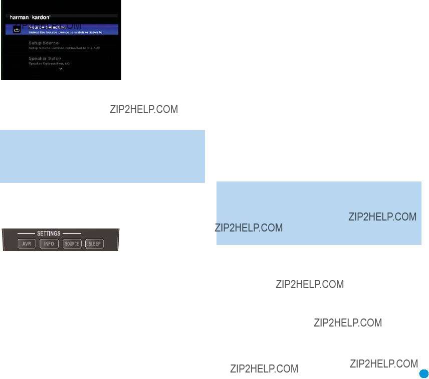
Before you begin enjoying your new receiver, a few adjustments should be made to configure the AVR 354 to match your actual system.
Make sure that you have connected a video display to one of the video monitor outputs on the receiver. When you turn on your display and the AVR, if the display is connected to the AVR via an analog video (com- posite,
Figure 47 ??? Main Menu
Although it???s possible to configure the AVR using only the remote and the
NOTE: When using the AVR???s
Using the
The menu system is accessed by pressing the AVR Settings Button on the remote. See Figure 48.
Figure 48 ??? Settings Buttons
The Main Menu will appear (see Figure 47), and if a video source is playing, it will be visible behind the transparent menu.
The menu system consists of five main menus: Source Selection, Setup Source, Speaker Setup, Zone 2 and System.
Use the ???/??/??? / ??? Buttons on the remote or front panel to navigate the menu system, and press the OK Button to select a menu or setting line or to enter a new setting.
INITIAL SETUP
The current menu, setting line or setting will appear in the Message Display as well as on screen.
To return to the previous menu or exit the menu system, press the Back/Exit Button. Be certain all settings are correct, as any changes you have made will be retained.
We recommend that most users follow the instructions in this INITIAL SETUP section to configure a basic home theater system. You may return to these menus at any time to make additional adjustments. Thanks to the EzSet/EQ system, most of the menu adjustments may be saved until you have become more familiar with the AVR, and are therefore described in the Advanced Functions section.
The Initial Setup section requires that you complete all of the steps in the Installation section that apply to your receiver. You should have
connected all of your loudspeakers and a video display, as well as your source devices. You should be able to turn on the receiver and view the main menu on your video display when you press the AVR Settings Button. If necessary, reread the Installation Section and the beginning of this section before continuing.
Configure the AVR 354 Using EzSet/EQ Technology
One of the most important and perhaps often overlooked aspects of setting up a home theater system is to calibrate the receiver to match the loudspeakers, which enables the AVR to perform at its best.
Until recently, most receivers required the user to perform the calibration and configuration manually, a somewhat tedious process that called for a good ear or the purchase of an SPL
the Advanced Features section, we recommend that you take advantage of our signature EzSet/EQ system.
Before beginning, eliminate extraneous background noise that might affect the results, such as noisy air conditioning. Try to avoid making any loud noises while running EzSet/EQ setup.
IMPORTANT SAFETY NOTE: During the EzSet/EQ procedure, a series of very loud test tones will be played through all of the speakers. Avoid sitting or standing close to any one speaker during the procedure. If you are particularly sensitive to loud noises, you may wish to leave the room and have someone else run the EzSet/EQ process.
Step One ??? Place the included EzSet/EQ microphone in the listening position, or in the center of the room, at about the same height as the listeners??? ears. The microphone features a threaded insert on the bottom so that it can be mounted on a camera tripod for stability.
Step Two ??? Plug the EzSet/EQ microphone into the Headphone Jack/EzSet/EQ Microphone Input Jack on the front of the receiver. See Figure 49.
35

INITIAL SETUP
Figure 49 ??? Plug EzSet/EQ microphone into receiver.
Step Three ??? Make sure that the AVR 354 and the video display are turned on. Press the AVR Settings Button to display the Main Menu. See Figure 47. Use the ?? Button to highlight the Speaker Setup line, and then press the OK Button. See Figure 50.
Figure 50 ??? Speaker Setup Menu Screen
Select ???Automatic
Figure 51 ??? EzSet/EQ Screen
At any time, you may select Cancel to return to the Speaker Setup menu without starting the EzSet/EQ process. When you are ready to begin, select Continue and press the OK Button.
NOTE: Before running the EzSet/EQ process, the AVR 354 will automatically set its master volume to
Step Four ??? After you select ???Continue???, the screen shown in Figure 52 will appear, directing you to select the number of speakers in your system. Select 5.1 if no surround back speakers are present, or if the surround back channels will be used for multizone operation.
Figure 52 ??? EzSet/EQ: Number of Speakers
NOTE: If you are using fewer than five main speakers in your system, it will not be possible to configure your speakers using the EzSet/EQ process; proceed as described in the Advanced Functions section. If you have selected a
The test will begin, and the screen shown in Figure 53 will appear, asking you to maintain silence during the EzSet/EQ configuration. If possible, turn off any noisy appliances, such as air conditioners.
Avoid conversation. If unwanted sounds are inadvertently heard during the test, such as a telephone, select Cancel to return to the Speaker Setup menu.
Figure 53 ??? EzSet/EQ in Progress
As EzSet/EQ tests each speaker, its position will appear on screen. Select Cancel to stop the test. If the test tone is heard from a different speaker than the one indicated on screen, turn off the AVR and check the
When the test is completed, the Continue option, will become available. Select it, and a screen will appear, listing all of the speakers the EzSet/EQ process detected, and offering three options:
???The Retest option reruns the EzSet/EQ process. Increasing the master volume manually at this time may enable the EzSet/EQ process to correctly detect some speakers.
???Selecting Cancel returns to the Speaker Setup menu.
???If the EzSet/EQ process detected the speakers correctly, select Continue to proceed to the next test.

INITIAL SETUP
Step Five ??? During the next portion of the test, the EzSet/EQ procedure equalizes the AVR 354???s audio circuitry to compensate for the specific room characteristics and the performance capabilities of each individual speaker. To do this successfully, the EzSet/EQ microphone must be placed about two feet from each speaker in the direction toward the listening position. Wait until the
When the EzSet/EQ process has finished, a screen will appear with its results.
See the Advanced Functions section for instructions on how to manually configure the speakers or manually adjust the settings established by the EzSet/EQ process.
Set Up Sources
The Source Info menu is used to assign the correct physical audio and video connections to each source. It also provides access to a variety of other settings, many of which may be adjusted later as you become more familiar with the AVR.
The following settings are not optional and must be adjusted now to enable playback of each source: Video Input from source, Audio Input from Source and Resolution to Display.
The other settings may be adjusted at any time to improve performance.
To display the Source Info menu, press the Info Settings Button (front panel or remote). A screen similar to the one shown in Figure 54
will appear. This screen may also be accessed from the Main Menu by selecting the Setup Source line and selecting a source from the
Figure 54 ??? Setup Source Menu
Audio Effects: Select this line to display the Audio Effects submenu,
where you may: adjust the bass and treble tone controls; adjust the LFE trim; or adjust the Night Mode setting. It is recommended that you leave this submenu at its default settings, and return to it later if your system requires any
Video Modes: Select this line to display the Video Modes submenu, to select from preprogrammed or custom picture settings and make picture adjustments. It is recommended that you leave the settings at their factory defaults. Picture adjustments should be made to your video display first, with this menu used only for
Surround Modes: Select this line to display the Surround Modes sub- menu, where you may program the desired surround mode for various types of analog programs, including movies, music and games. You may also specify a stereo mode (depending on the number of channels desired) and a virtual surround mode if your system uses fewer than the full complement of seven main speakers (plus a subwoofer).
Digital surround signals, such as Dolby Digital and DTS, are automatically played in their native formats, although you may change the surround mode at any time. See the Advanced Functions section for information on surround modes available with digital programs.
In the factory default Auto Select mode, the AVR will analyze the source signal and select the optimum playback mode. The AVR???s default is to use the Logic 7 Movie mode for optimal playback of movies, including tele- vision programs; the Logic 7 Music mode for music recordings, such as CDs; and the Logic 7 Game mode when a video game console is in use. Select a surround mode corresponding to your selection, i.e. a movie, music or a video game. To reprogram any of the lines in the Surround Modes menu, select it and choose from the list of available surround modes. Whenever you manually select the mode during playback, the AVR will use the new surround mode.
Selecting a surround mode is a matter of taste, although the available modes depend on the number of speakers in your system and the format of the incoming signal. Feel free to experiment by selecting any available mode at any time until you find a few modes that you prefer. See the Advanced Functions section for more information.
Audio Format From Source: This line is informational only. When a digital program is playing, its format will be identified here. When analog audio programs are playing, this line indicates NO AUDIO INPUT, referring to digital inputs only.
Audio and Video Input Selection
Please see Table A2 in the appendix for the factory default input assign- ments for each source. You may assign any available input to any source using the Source Info menu, accessible either by pressing the AVR Settings Button and selecting the Setup Source line, or by pressing the Info Settings Button for direct access.
When a source is selected, the AVR will check the assigned digital audio input for a signal. If one is present, the digital input will be selected. If not, the AVR will select the analog audio input specified at the Audio Auto Polling line of the Setup Source menu. If you don???t want the AVR to select an analog audio input for the source, change this setting to Off.
The AVR will also select the assigned video source. There are no ???audio- only??? sources on the AVR 354, other than the Radio, which uses a special
NOTE: The Bridge II obtains its audio and video signals (when available) from the iPod docked in it, and it may not be used with other audio or video sources.
37

INITIAL SETUP
Video Input From Source: Select this line to assign the correct
video input to the source. Refer to Table A5 in the appendix, where you noted the physical video input the source is connected to, and select the input here.
Audio Input From Source: Select this line to assign the correct analog or digital audio input to the source. Refer to Table A5 in the appendix, where you noted the physical audio input the source is connected to, and select the input here. If both analog and digital audio connections were made, select the digital input here, and select the analog input at the Audio Auto Polling line below.
The
???Connect the player???s HDMI output to one of the AVR???s HDMI Inputs. No other connections are necessary.
???Assign the HDMI Input to both the Audio and Video Input from source settings in the Source Info menu.
???Connect the player???s HDMI output and its multichannel analog audio outputs to one of the AVR???s HDMI Inputs and to the AVR???s
???Assign the HDMI Input to both the Audio and Video Input from source settings in the Source Info menu.
???Assign the
???When listening to
???When listening to
Multichannel Disc Player Without HDMI Output, or When Video Display Has No HDMI Input:
???Connect the player???s component video outputs to one set of Component Video Inputs on the AVR. Depending on the capabilities of the player and your video display, you may need to use a composite or
???Connect the player???s digital audio output to a corresponding available digital audio input on the AVR.
???Connect the player???s multichannel audio outputs to the AVR???s
???Assign the correct audio and video inputs to the Audio and Video Input from source Settings in the Source Info menu.
???Assign the
???When listening to
???When listening to
NOTE: The
Resolution to Display: This setting, which may also be accessed from the AVR Settings menu, reflects the video output resolution, which is dependent upon the capabilities of the video display.
???If the display is connected to the AVR???s HDMI Output, the HDMI pro- tocol enables the two devices to communicate with each other, and the AVR will automatically select the correct video output resolution.
???If the display is connected to the AVR???s Component Video Outputs, there is no automatic detection of the display???s capabilities, and the video output resolution must be manually adjusted to match the display???s capabilities (which may be obtained from the display???s manual or its manufacturer???s Web site).
???If the display is connected to the AVR???s Composite or
Since there is no picture if the resolution is set higher than the display???s capability, adjust the resolution by pressing the
Press the ?? Button to view the ACCEPT option, and then press the OK Button to complete the change to the output resolution.
NOTE: When the display has a DVI input which is connected to the AVR using an

INITIAL SETUP
Resolution From Source: This line, which is informational only, indi- cates the video format (NTSC or PAL) output by the source device. NTSC is the video format used for
Adjust Lip Sync: Use this adjustment to resynchronize the audio and video signals from a source to eliminate a ???lip sync??? problem. Lip sync issues can occur when the video portion of a signal undergoes additional processing in either the source or the video display that desynchronizes it from the audio. Select this line to display the Lip Sync adjuster by itself, enabling you to view the video while listening to the audio. Use the ??? / ??? Buttons to delay the audio by up to 180ms. See Figure 55.
Zone 2 Audio: When a multizone system has been connected and is in use, this setting determines the source for the remote zone. Select the analog audio input the source is connected to. Digital audio is not available to the multizone system, nor is any type of video.
Use the Back/Exit Button to exit, then return to the Setup Source line of the Main Menu and select the next source to configure. When you have finished configuring all sources, press the Back/Exit Button to clear the menus from view.
You are now ready to begin enjoying your new receiver!
Figure 55 ??? Adjust Lip Sync
Change Name: Use this line to change the display name for your source. This can be useful if your source???s device type is different from the available source names. Select this line and use the ???/?? Buttons to scroll forward or reverse through the letters A through Z and the numbers 0 through 9. When the desired character appears, use the
??? Button to move the cursor to the next position. Move the cursor again to leave a blank space. When you have finished entering the new name, press the OK Button. The name will be used on the front panel to refer to the source, and will appear next to its original name, e.g., DVD, throughout the
Audio Auto Polling: Use this setting when both analog and digital audio connections are made from the source device to the AVR. When no digital signal is present, the AVR will automatically switch to the analog audio input.
This can be useful for some older cable television systems that broad- cast some channels in analog audio and others in digital audio. It is also useful for making analog recordings of
If an analog audio connection was made, select it here. If not, choose the Off setting, and the AVR will always use the digital audio connection.
39
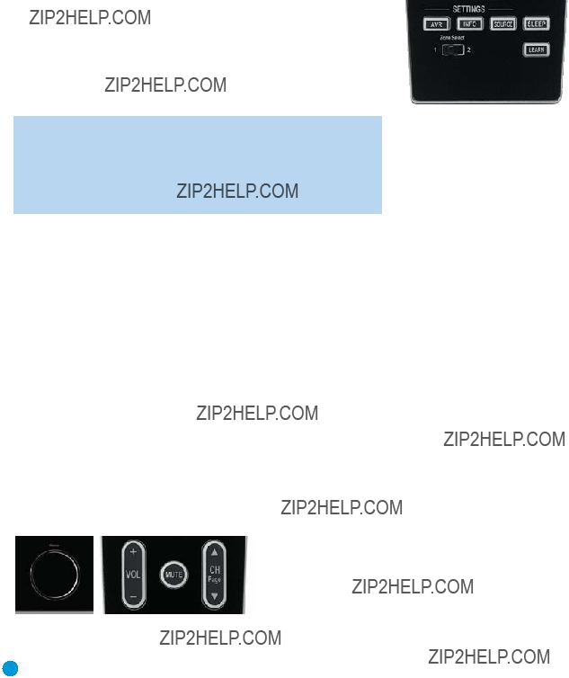
OPERATION
Now that you have installed your system components and completed a basic configuration of your receiver, you are ready to begin enjoying your home theater system.
Turning On the AVR 354
Gently press the Master Power Switch until the word OFF is no longer visible. The Power Indicator above the two power switches should light up in amber. This indicates that the AVR is in Standby mode and is ready to be turned on. Normally, you may leave the Master Power Switch in the ON position, even when the receiver is not being used. See Figure 45.
There are several ways in which the AVR 354 may be turned on:
a)Press the Standby/On Switch on the front panel. See Figure 45.
b)Using the remote, press the AVR Power On Button or any of the Source Selectors. See Figure 46.
To turn the receiver off, press either the Standby/On Switch on the front panel, or press the AVR Power Off Button on the remote. Unless the receiver will not be used for an extended period of time (for example, when are on vacation), it is not necessary to turn off the Master Power Switch. When the Master Power Switch is turned off, any settings you have programmed, including system configuration and preset radio stations, will be preserved for up to four weeks.
IMPORTANT NOTE: If the PROTECT message ever appears in the Message Display, turn off the AVR and unplug it. Check all speaker wires for a possible short. If none is found, bring the unit to an authorized Harman Kardon service center for inspection and repair before using it again.
Volume Control
The volume may be adjusted either by turning the knob on the front panel (clockwise to increase volume or counterclockwise to decrease volume), or by pressing the Volume Control on the remote. See Figure 56. The volume is displayed as a negative number of decibels (dB) below the 0dB reference point.
Unlike the volume controls on some other products, 0dB is the maximum volume for the AVR 354. Although it???s physically possible to turn the volume to a higher level, doing so may damage your hearing and your speakers. For certain more dynamic audio materials, even 0dB may be too high, allowing for damage to equipment. We urge caution with regard to volume levels.
You may change the volume level display from the default decibel scale to a
Figure 56 ??? Volume Controls
Mute Function
To temporarily mute all speakers and the headphones, press the Mute Button on the remote. See Figure 56. Any recording in progress will not be affected. The MUTE message will appear in the display as a reminder. To restore normal audio, either press the Mute Button again, or adjust the volume. Turning off the AVR will also end muting.
Sleep Timer
You may program the AVR to play for up to 90 minutes and then turn off automatically using the sleep timer.
Press the Sleep Settings Button on the remote, and the time until
Figure 57 ??? Sleep Settings Button
When the sleep timer has been set, the
If you press the Sleep Button after the timer has been set, the remaining time until
Audio Effects
Depending on your preferences or the specific characteristics of your listening room, you may wish to adjust some of the audio settings, such as tone controls, to improve performance. Access these settings from the Audio Effects submenu, as described in the Advanced Functions section.
It is not necessary to adjust the Audio Effects settings to enjoy your new AVR. We recommend leaving the settings at their default values until you are more familiar with your system.
Video Modes
The settings in the Video Modes menu are used to
Headphones
Plug the 1/4" plug on a pair of headphones into the headphone jack on the front of the receiver for private listening. See Figure 58.
40
The DOLBY H:BYPASS message indicates that Dolby Headphone surround processing is in the default bypass mode, which delivers a conventional
Figure 58 ??? Headphone Jack
Press the Surround Modes Button on the front panel or the remote, to switch to Dolby Headphone virtual surround processing, indicated by the DOLBY H:DH message. Dolby Headphone delivers an enhanced sound field that emulates a
Source Selection
Press the
Figure 59 ??? Source List Button
For direct access to any source, press its Source Selector on the remote.
The AVR 354 will switch to the audio and video inputs assigned to the source.
The source name will appear in the upper line of the
Any other settings you adjusted in the Setup Source menu will also be selected. You may view these settings in the Source Info menu at any time by pressing the Info Settings Button.
VIDEO TROUBLESHOOTING TIPS:
If a video source is playing and there is no picture:
???Check that you have selected the source to which the video input was assigned.
???Check the wires for a loose or incorrect connection.
???Check that you have selected the correct video input on the display device (TV).
???Try pressing the Resolution Button on the front panel repeat- edly until the correct video output resolution is selected and a picture appears. You will be prompted to accept or cancel the resolution change, as the CANCEL message will appear on the front panel. Press the ?? Button to view the ACCEPT option, and then press the OK Button to complete the change to the output resolution.
OPERATION
Additional Tips for Systems Using HDMI:
???Turn off all devices (including the TV, AVR and any source components).
???Unplug the HDMI cables starting with the cable between the TV and AVR, and continuing with the cables between the AVR and each source device.
???Carefully reconnect the cables from the source devices to the AVR, and connect the cable from the AVR to the TV last.
???Turn on the devices in this order: TV, then AVR, then source devices.
Using the Tuner
To select the AVR 354???s
1.Press the Source List Button on the front panel repeatedly until the desired tuner band is selected, or use the ???/?? Buttons to scroll through the source list.
2.Press the Radio Source Selector on the remote. Press this button again to switch bands (AM, FM or XM).
A screen similar to the one shown in Figure 60 will appear, with the band indicated in the middle of the screen. (The XM band uses a slightly different screen.)
Figure 60 ??? FM Radio
Use the ???/?? Buttons to tune a station (or channel for XM Radio). The frequencies will be displayed in the front panel and graphically on screen.
The AVR defaults to automatic tuning, meaning each press of the
???/?? Buttons scans through all frequencies until a station with accept- able signal strength is found. To switch to manual tuning, in which each press of the ???/?? Buttons steps through a single frequency increment (0.1MHz for FM, or 10kHz for AM), press the Menu Button. The Radio Modes line will be highlighted, and each press of the OK Button toggles between automatic and manual tuning modes.
When an FM station has been tuned, toggling the radio mode switches between stereo and monaural play, which may improve reception of weaker stations.
A total of 30 stations (AM and FM together) may be stored as presets. When the desired station has been tuned, press the OK Button, and two dashes will flash in the
41

OPERATION
To tune a preset station, press the ??? / ??? Buttons or the Channel Control, or press the Menu Button to view the list of programmed pre- sets and scroll to the desired selection. Press the OK Button to tune the station. You may also enter the preset number using the Numeric Keys. For presets 10 through 30 press 0 before the preset number. For example, to enter preset 21, press
XM Radio Operation
XM Radio is a
Select an antenna module designated for XM Ready audio components. An XM
The XM
use is also compatible, but has been discontinued and may no longer be available. Additional modules may become available in the future. Modules produced for automotive, or ???mobile,??? use are not compatible with the AVR 354, although if they have standard analog or digital audio outputs, they may be connected to a compatible input and operated using their own controls.
NOTE: To listen to XM Radio using the AVR 354, you will need to purchase an XM antenna module and subscription, and activate your module. XM service is not available in Alaska or Hawaii. Visit the XM Radio Web site at www.xmradio.com for more information.
Plug the module into the XM Antenna Jack on the rear of the AVR 354. Place the antenna module so that it has a clear view through a south- facing window in order to obtain reception from the XM satellite.
Select XM Radio as the source in one of these ways:
1.Press the Source List Button on the front panel repeatedly until XM Radio is selected, or use the ??? /?? Buttons to scroll through the source list.
2.Press the Radio Source Selector on the remote repeatedly until XM Radio is selected..
You should be able to tune in Channel 1, the Preview Channel, to confirm that your equipment is ready for activation. There are four ways to tune an XM Radio channel:
1.Press the Menu Button to select a search mode: preset, category, all channels (the default) or direct entry.
2.Use the ??? /?? Buttons to scan through the channel numbers in
the default All Channel search mode. If you press the OK Button first, pressing the ??? /?? Buttons will scan through any preset positions you have programmed (Preset search mode).
3.In Category search mode, use the ??? / ??? Buttons to jump to the next category, and then use the ??? /?? Buttons to scan through the channel numbers within the category.
4.After you have programmed presets, directly enter the preset number (1 through 40) using the Alphanumeric Keys. For
When you are able to hear Channel 1, you are ready to activate your module. If you don???t hear Channel 1, make sure the module???s plug is firmly seated in the XM Antenna jack, and that the module is near a
Tune to Channel 0 for a display of your antenna module???s Radio ID number, required for activation.
The current channel number and preset location will appear in the upper line of the Message Display, and the search mode (all channels, category) will appear in the lower line. Three
on screen when a video display is in use.
For traffic and weather channels, the current city???s name will appear instead of the channel name, and the local weather and temperature will be displayed on screen.
To store a channel in one of the 40 preset locations:
1.Tune to the desired channel and press the OK Button. The lowest available preset number will flash on screen and in the
2.Use the Alphanumeric Keys to enter the numbered preset location you wish to store the channel in, or do nothing if the current preset location is acceptable.
3.Press the OK Button to store the new preset.
Recording
42

OPERATION
NOTES:
1.Analog audio signals are not converted to digital form, and digital audio signals are not converted to analog audio form. However, you may record a coaxial or optical digital audio source using either type of digital audio output.
2.Only PCM digital audio signals are available for recording. Proprietary formats such as Dolby Digital and DTS may not be recorded using the digital audio connections, although if the source is connected to the AVR using analog audio connections, an analog recording may be made.
3.HDMI and component video sources are not available for recording.
4.Please make certain that you are aware of any copyright restrictions on any material you record. Unauthorized duplica- tion of copyrighted materials is prohibited by federal law.
Using  Docking Station
The Bridge II is an included dock that is compatible with most docking iPod models, 4G and later (not included). When The Bridge II is con- nected to its proprietary input on the AVR 354 and the iPod is docked, you may play the audio, video and
and charge the iPod.
Either press the
When The Bridge II is connected, the screen shown in Figure 61 will appear on a video display connected to the AVR.
Figure 61 ??? The Bridge
Press the Menu Button to view the
Back: This option appears while navigating the contents of the iPod only. Select it to return to the previous screen.
Music: Select this line to navigate the audio materials stored on the iPod.
Photos: Select this line to view still images stored on a
If the iPod supports video browsing, visual materials may be displayed on a video monitor connected to the AVR as follows: Select the desired photo and press the Play Button on the iPod itself to begin slideshow playback. If you use the AVR???s remote, press the OK Button three times.
Videos: This line may appear, but cannot be selected. If the iPod sup- ports video browsing, you may view videos on an external monitor by following this procedure: Select the Photos line in the
NOTES ON VIDEO PLAYBACK:
???As of this writing, video browsing is only supported on the iPod 5G, iPod classic and iPod nano 3G. For other iPod models, it is not possible to view photos or videos on an external monitor while using The Bridge II. However, you may pur- chase a compatible A/V cable from Apple Inc. that has a dock connector on one end and conventional audio and video plugs on the other end. The audio/video plugs may be con- nected to any available analog inputs on the AVR, as you would for any other source device.
???Before attempting to view photos or videos stored on your iPod, check the Video Settings menu on the iPod and make sure that the TV Out setting is set to On. The TV Signal setting should be NTSC to match the capabilities of your video dis- play. Set Widescreen to On or Off, depending on the aspect ratio of your video display. If your selection was playing and paused, the iPod requires you to reselect the video for the new TV Out setting to take effect.
???In iPod Manual Mode, the iPod menus will only be visible
on the iPod screen itself. You may operate the iPod using the AVR remote, as long as it is in The Bridge device mode.
???The MP4 and H.264 video formats often used for videos to be played on the iPod are intended for optimal performance on the small screen of the iPod. Playback on larger displays may have different results.
After selecting photo or video viewing, the AVR may remain in iPod Manual Mode, even after undocking the iPod or switching to another source input and back again. To return to normal operation, with the AVR remote in The Bridge mode, press and hold the Menu Button.
Random: Select this setting for random playback, also known as ???Shuffle Mode???. Each press of the OK Button switches the setting: shuffle by Song, shuffle by Album, or Off to end random playback.
Repeat: Select this setting to repeat a track or all tracks in the current album or play list. Each press of the OK Button switches the setting: repeat Off, repeat One or repeat All.
43

OPERATION
NOTE: The iTunes application allows you to set certain selections to always be skipped in Shuffle mode. The AVR 354???s settings cannot override these iTunes settings.
Table 2 summarizes the controls available when The Bridge II is in use.
Table 2 ??? Using The Bridge II
While scrolling, hold the key to scroll faster. Use the Page Up/Down control on the remote to scroll a page at a time.
NOTES:
???The Play and Pause functions are not available unless content has been selected for playback by navigating the menu system.
???To search within a track, press and hold the indicated button. Pressing the Previous Track Button once skips to the beginning of the current track. Press the Previous Track Button twice to skip to the beginning of the previous track.
While a selection is playing, the song title, artist and album name, if available on the iPod, will appear in the upper line in the
In addition, if a video monitor is connected to the AVR 354 and the system is not in iPod Manual Mode, it will display information about the status of the iPod and the track, including the play mode icon, the song title, artist and album. A graphic bar indicates the current play position within the track. If random or repeat play has been programmed, an icon will appear in the upper right corner.
After a period of time, the screen may disappear from view. The length of time is set using the Setup and
NOTE: It is strongly recommended that you use a screen saver built into your video display to avoid possible damage from
Selecting a Surround Mode
Surround mode selection can be as simple or sophisticated as your individual system and tastes. Feel free to experiment, and you may find a few favorites for certain sources or program types. More detailed information on surround modes may be found in the Advanced Functions section.
To select a surround mode, press the Surround Modes Button (front panel or remote) repeatedly until the desired option appears:
SURR: AUTO SELECT, SURR: VIRTUAL, SURR: STEREO, SURR: MOVIE,
SURR: MUSIC or SURR: GAME. The option will be displayed in the Lower Line of the Message Display, and the Surround Modes menu will appear on screen (see Figure 62).
Figure 62 ??? Surround Modes Menu
Auto Select: For digital programs, such as movies recorded with a Dolby Digital soundtrack, the AVR will automatically use the native surround format. For
Virtual Surround: When only two main speakers are present in the system, Dolby Virtual Surround may be used to create an enhanced soundfield that virtualizes the missing speakers. Select between Wide and Reference modes, depending on your preferences.
Stereo: When
???2 CH STEREO for playback through only two speakers. As described on page 45, you may select Analog Bypass mode for a pure analog signal when analog audio inputs are in use. Simply set the Tone Control setting in the Audio Effects submenu to Off, and the AVR does the rest.
???5 CH STEREO for playing the
???7 CH STEREO follows the same scheme as 5 CH STEREO, but adds the surround back speakers to the mix. This mode is only available when the surround back speakers are present and have not been reassigned to multizone operation. See the Initial Setup section for more information.
Movie: Select an analog surround mode for movie playback: Logic 7 Movie, DTS Neo:6 Cinema or Dolby Pro Logic II (IIx when seven main speakers are present). The desired mode may also be selected when a compatible digital surround mode is received.

ADVANCED FUNCTIONS
Music: Select an analog surround mode for music playback: Logic 7 Music, DTS Neo:6 Music or Dolby Pro Logic II (IIx when seven main speakers are present). The Dolby Pro Logic II/IIx Music mode allows access to a submenu with some additional settings. See the Advanced Functions section for more information.
Video Game: Select an analog surround mode for game playback: Logic 7 Game, or Dolby Pro Logic II (IIx when seven main speakers are present).
After you have made your selection, press the Back/Exit Button until the screen is cleared.
See the Advanced Functions section for more information on surround modes.
Much of the AVR 354???s performance is handled automatically, with little intervention required on your part. However, the AVR 354 is a sophisti- cated component, and is capable of being customized to suit your particular system and your tastes. In this section we describe some of the more advanced adjustments available on the AVR 354. You may return to this section later, when you have become more familiar with your receiver.
Audio Processing and Surround Sound
Audio signals output by sources are encoded in a variety of formats that can affect not only the quality of the sound but the number of speaker channels and the surround mode. You may also manually select a different surround mode, although for certain types of audio signals,
the modes available will be limited in certain ways, as described below.
Analog Audio Signals
Analog audio signals usually consist of two channels ??? left and right. The AVR 354 offers three basic options for playback of analog audio:
1.Analog Bypass Mode: In this mode, the
a)The analog audio inputs for the source must be selected. If necessary, press the Info Button on the remote and use the ??? /?? Buttons to scroll to the Audio Input from source setting, then select an analog input.
b)The tone controls must be disabled by setting Tone Control to Off. Press the Audio Effects Button to access the Tone Control setting in the Audio Effects submenu.
c)The
When the Tone Control setting is Off, the front speakers will be set to Large automatically, as indicated by the double boxes in their positions in the Speaker/Channel Input Indicators on the front panel. That indicates that Analog Bypass mode is active. When the Tone Control setting is
turned On, if you have set the front speaker crossover to a numeric setting, the front speakers will return to the Small setting, as indicated by single boxes in the Speaker/Channel Input Indicators. When the front speakers are Small and
2.DSP Surround Off Mode: The DSP Surround Off mode digitizes the incoming signal and applies the bass management settings, including speaker configuration, delay times and output levels. This mode is desirable when your front speakers are small,
3.Analog Surround Modes: One of the main benefits of a surround receiver such as the AVR 354 is its ability to process
Digital Audio Signals
Digital audio signals offer the benefit of greater capacity, which allows recording artists to encode center and surround channel information directly into the signal. The result is improved sound quality and startling directionality, since each of these channels is reproduced discretely.
Alternatively, the artist may encode only two channels, but the digital signal allows for a higher sampling rate that delivers greater detail.
Surround Modes
Surround mode selection is dependent upon the format of the incoming audio signal, as well as personal taste. There is no harm in experiment- ing with all of the modes available with any given source material. Table A12 offers a brief description of each mode the AVR 354 is capable of using, and also indicates the types of incoming signals or digital bit- streams the mode may be used with. Additional information about the Dolby and DTS modes is available on the companies??? Web sites: www.dolby.com and www.dtsonline.com.
When in doubt, check the jacket of your DVD for more information on which surround modes are available on the disc. Usually, nonessential sections of the disc, such as trailers, extra materials or the disc menu, are only available in Dolby Digital 2.0
As indicated in Table A12, different surround modes may only be available with certain input signals or bitstream formats. For any
45

ADVANCED FUNCTIONS
incoming signal, only a limited number of surround modes are available. Although there is never a time when all of the AVR 354???s surround modes are available, there is usually a wide variety of modes available for a given input.
Multichannel digital recordings usually are found in the
NOTE: To use the 6.1- and
Digital formats include Dolby Digital 2.0 (two channels only), Dolby Digital 5.1, Dolby Digital EX, Dolby Digital Plus, Dolby TrueHD,
or 96kHz, and 5.1 or 7.1 multichannel PCM.
When a digital signal is received, the AVR 354 detects the encoding method and the number of channels. The number of channels encoded will appear briefly in the
The first number indicates the number of front channels in the signal:
???1??? represents a monophonic recording, usually an older program that has been digitally remastered or, more rarely, a modern program for which the director has chosen a special effect.
???2??? indicates the presence of the left and right channels, but no center channel.
???3??? indicates that all three front channels (left, right and center) are present.
The second number indicates whether any surround channels are present:
???0??? indicates that no surround information is present.
???1??? indicates that a matrixed surround signal is present.
???2??? indicates discrete left and right surround channels.
???3??? is used with
???4??? is used with
The third number is used for the LFE channel:
???0??? indicates no LFE channel.
???.1??? indicates that an LFE channel is present.
The
For Dolby Digital EX materials, the incoming bitstream will be displayed as 3/2/.1
For
When a PCM signal is received, the PCM message, followed by the sampling rate of the signal (32kHz, 44.1kHz, 48kHz or 96kHz), will appear in the
In addition, the Speaker/Channel Input Indicators will indicate the number of channels discretely encoded in the signal by displaying a letter inside that channel???s speaker box. A line will connect the SBL and SBR boxes when a
C
L R
LFE
SL SR
When only two channels ??? left and right ??? are present, the analog surround modes may be used to decode the signal into the remaining channels.
If you would prefer a different surround format than the native signal???s digital encoding, press the Surround Modes Button to display the Surround Modes menu (see Figure 62).
The Auto Select option (the first line) uses the native signal???s digital encoding, e.g., Dolby Digital or DTS. For
AVR defaults to Logic 7 Movie mode. If you prefer a different surround processing mode, select the appropriate line from the menu: Virtual Surround, Stereo, Movie, Music or Video Game.
Each line is set to a default surround mode:
???Virtual Surround: Dolby Virtual Speaker Reference
???Stereo:
???Movie: Logic 7 Movie
???Music: Logic 7 Music
???Video Game: Logic 7 Game
You may change each line???s setting to a different surround mode. The choice of new modes depends on the number of speakers in your system.
???Virtual Surround: Dolby Virtual Speaker Reference or Wide
???Stereo:

ADVANCED FUNCTIONS
???Movie: Logic 7 Movie, DTS Neo 6:Cinema, Dolby Pro Logic II Movie, Dolby Pro Logic IIx Movie
???Music: Logic 7 Music, DTS Neo 6:Music, Dolby Pro Logic II Music, Dolby Pro Logic IIx Music
???Video Game: Logic 7 Game, Dolby Pro Logic II Game, Dolby Pro Logic IIx Game
When one of the Dolby Pro Logic II Music modes is selected, access to the Edit submenu becomes available. This submenu may be used to adjust special settings available only in Music mode: Center Width, Dimension and Panorama.
Once you have programmed the default surround mode for each type of program, simply select the line from the Surround Modes menu any time you wish to override the AVR???s automatic surround mode selection. The AVR will use the same surround mode the next time the source input is selected.
Please refer to Table A12 in the appendix for more information on which surround modes are available with different bitstreams.
NOTE: Dolby Digital 2.0 signals may also include a Dolby Surround flag indicating
Dolby Surround Settings
Some additional settings are available for Dolby modes. Three settings are active only when the Dolby Pro Logic II or IIx Music modes have been selected. See Figure 64.
Panorama: With the Panorama mode turned ON, some of the sound from the front speakers is moved to the surround speakers, creating an enveloping ???wraparound??? type of effect. Each press of the OK Button toggles the setting on or off.
Night Mode
Night mode is available with some Dolby Digital programs, if it has been encoded in the material. It compresses the peak sound levels, maintain- ing the intelligibility of the dialogue and quieter passages, while reducing the loudness of special effects and louder passages to avoid disturbing others. Night Mode is accessed from the Audio Effects menu. Press the Audio Effects Button and scroll down to the Night Mode line. Three levels of compression are available:
Off: At this setting, there is no compression, as the Night mode is deactivated.
Half: A mild compression is applied.
Full: More compression is applied.
Table A12 provides descriptions of all surround modes available on the AVR 354, along with the incoming bitstreams or signals that the particular mode may be used with. Feel free to experiment and simply cycle through all of the available modes at any time; you cannot cause any problems for the AVR 354 by doing so.
NOTE: To access 6.1- and
Figure 64 ??? Dolby Pro Logic II/IIx Music Mode Settings
Center Width: This setting affects how vocals sound through the three front speakers. A higher number (up to 7) focuses the vocal information tightly on the center channel. Lower numbers broaden the vocal sound- stage across the three speakers. Use the ??? / ??? Buttons to change
the setting.
Dimension: This setting affects the depth of the surround presentation, allowing you to ???move??? the sound toward the front or rear of the room. The setting of ???0??? is a neutral default. Setting
47

ADVANCED FUNCTIONS
Manual Setup
The AVR 354 is flexibly designed to be used with almost any loud- speakers available. The flexibility comes from the AVR 354???s capability to be configured to match the characteristics of your particular speakers, and to compensate for the acoustic characteristics of your room.
The EzSet/EQ process automatically detects the capabilities of each speaker, and optimizes the AVR 354???s performance in your system. However, if for some reason you are unable to run EzSet/EQ calibration, e.g., you have misplaced the microphone, or if you wish to make further adjustments to the settings made by the EzSet/EQ process, you may use the Manual Setup
Before beginning manual setup place your loudspeakers in their correct locations within the room (see Speaker Placement section), and connect them to the AVR. You will need the specifications for each of your speakers, which may usually be found in the owner???s guide for the speakers or
on the manufacturer???s Web site. If necessary, contact the manufacturer to obtain the frequency range specification. Although the
We suggest that you record your configuration settings in the appropri- ate places in Tables A3 through A11 in the appendix in case you need to reenter them after a system reset, or if the AVR???s Master Power Switch is turned off or the unit is unplugged for more than four weeks.
NOTE: When using the AVR???s Speaker Setup menus, we rec- ommend selecting a video output resolution of 720p or higher to provide graphics that simplify configuration. Those menus will vary in appearance from the ones shown here.
Step One ??? Determine Speaker Crossover
Without using the EzSet/EQ process, the AVR 354 can???t detect how many speakers you???ve connected to it; nor can it determine their capa- bilities. For this part of the system setup consult the speaker???s technical specifications.
Locate the frequency response, which is usually given as a range, e.g., 100Hz ??? 20kHz (??3dB). This specification tells you whether the speaker is able to play sounds that are very high- or
The subwoofer???s frequency response will include only the very lowest frequencies, since the subwoofer is designed to play only bass materials. A typical frequency response for a subwoofer is 25Hz ??? 150Hz. In this case, the higher number should be noted in the worksheet.
This information is required to program the receiver???s bass manage- ment, which determines which speakers the receiver will use to play back the
If you send the lowest notes to small satellite speakers, you won???t hear these notes very well, and you may even damage the speaker by exceeding its capabilities. If you send the highest notes to the special- purpose subwoofer, you may not hear them at all.
With proper bass management, the AVR 354 divides the source signal at a crossover point. All information above the crossover point is played through the satellite speaker (front left/right, center, surround left/right, or surround back left/right), and all information below the crossover point is played through the subwoofer. This enables each loudspeaker in your system to perform at its best, delivering an enjoyable sound experience.
Step Two ??? Measure Speaker Distances
Ideally, all of your speakers would be placed in a circle, each at the same distance from the listening position. However, your room may not be ideal, and you may have had to place some speakers a little further away than others. This could affect the overall sound of the receiver, as sounds that are supposed to arrive simultaneously from different speakers blur due to different arrival times.
The AVR 354 has a delay adjustment that enables the receiver to compensate for
Before you begin making adjustments, measure the distance from each speaker to the listening position, and note it in the Table A4 worksheet in the appendix. Even if all of your speakers are the same distance from the listening position, you should enter your speaker distances as described in Step Three.
Step Three ??? Manual Setup Menu
Now you are ready to program these adjustments into the receiver. It???s best to sit in the usual listening position and make the room as quiet as possible.
With the receiver and video display turned on, press the AVR Button to display the menu system. Use the ?? Button to move the cursor to the Speaker Setup line, and press the Set Button to display the Speaker Setup menu. See Figure 50.
If you have run the EzSet/EQ process, those results were saved. To tweak the EzSet/EQ results, or to configure the AVR from scratch, select Manual Setup. The screen shown in Figure 65 will appear.
Figure 65 ??? Manual Speaker Setup Menu

ADVANCED FUNCTIONS
NOTE: All of the speaker setup submenus include the Exit and Back options as shown at the bottom of Figure 65. To return to a previous menu without making any changes, select Exit. To save the current settings, select the Back option.
If you previously saved EzSet/EQ results in this setup position and you wish to reconfigure the speakers from scratch, select the Reset option.
For best results, we recommend configuring the speakers in this order, although it may differ from the order in which the submenus appear in the Manual Speaker Setup menu: Number of Speakers, Crossover (Size), Sub Mode, Distance and Level Adjust.
Number of Speakers
Move the cursor to the Number of Speakers line and press the Set Button. See Figure 66.
Figure 66 ??? Number of Speakers Menu
The Number of Speakers menu lists each of the speaker groups. Program the correct setting for each group: ON when the speakers are present in the system, and OFF for positions where no speakers have been installed. The Front Left & Right speakers are always ON and may not be disabled. Any changes made to the system configura- tion will be reflected in the total number of speakers displayed at the top of the screen.
The setting for the surround back speakers includes a third option: Zone 2. The AVR 354 is capable of multizone operation, allowing place- ment of a pair of speakers in another room. Listeners in the remote room may enjoy either the same program as in the main room or a different source. The AVR 354???s assignable surround back amplifier channels make multizone operation easier than ever, since an external power amplifier is not required. Simply select the Zone 2 option at this line, and connect the Surround Back Speaker Outputs to loudspeakers located in the remote room. The main room will be configured automatically for up to 5.1 channels. See the Multizone Operation section for more information.
The settings in this menu affect a number of aspects of the AVR???s operation, including the remainder of the speaker setup process and the availability of various surround modes at any time.
When you have finished programming the number of speakers in the system, select the Back option to insure the settings are saved correctly. You may use the Back/Exit Button, and the settings will be saved.
Adjust Crossover Frequencies Menu
After you have programmed the number of speakers in the system, the AVR will return to the Manual Speaker Setup menu, similar to the one shown in Figure 50. Navigate to the Crossover (Size) line and press the OK Button to display the Adjust Crossover Frequencies menu (see Figure 67).
Figure 67 ??? Adjust Crossover Frequencies Menu
The AVR will only display those speaker groups which you programmed in the Number of Speakers menu.
Refer back to Step One, where you determined each speaker???s crossover. For the main speakers, this is the lowest frequency the speaker reproduces well; and for the subwoofer, it???s the highest.
For each main speaker, select one of the seven crossover frequencies: 40Hz, 60Hz, 80Hz, 100Hz, 120Hz, 150Hz or 200Hz. If the crossover frequency you determined in Step One is below 40Hz, select the first option, ???Large???. This setting doesn???t refer to the speaker???s physical size, but to its frequency response, which is also called ???full range???. This means the speaker is capable of playing sounds throughout the frequency spectrum, from the high pitches to the bass.
Specify the size of the subwoofer???s transducer as 8, 10, 12 or 15 inches.
Make a note of each speaker group???s crossover setting in Table A3 in the appendix.
When you have finished entering the settings, remember to select Back, not Exit.
Sub Mode
Move the cursor to the Sub Mode line to program bass management for the subwoofer. The subwoofer???s setting depends upon how you programmed the front left and right speakers.
???If you set the front speakers to a numeric crossover frequency, the subwoofer setting will be LFE, and you won???t be able to change it. All
???If you set the front speakers to LARGE, you may select between two possible settings for the subwoofer.
 L/R+LFE: This setting sends all

ADVANCED FUNCTIONS
be played through the front left and right speakers and the special
 LFE: This setting plays
NOTE: If you are using a Harman Kardon HKTS Series speaker system, select the appropriate numeric crossover frequency for the Left/Right, Center, Surround and Surr Back lines, and the subwoofer will automatically be set to LFE.
The Speaker/Channel Indicators on the front panel of the receiver (see Figure 63) will display the speaker size settings as follows. For each speaker configured numerically, a single box will appear in the position for that speaker. For each speaker configured as LARGE, a double box will appear in its position. If a speaker is configured as OFF, no box will appear. The subwoofer will be indicated by a single box, or no box if no subwoofer has been configured. The letters inside the boxes appear when a digital signal is being received that has that channel discretely encoded. The letters flash when the signal is not present, such as when a DVD is paused. A line will connect the SBL and SBR boxes when a
Adjust Speaker Distance Menu
As explained above in Step Two ??? Measure Speaker Distances, some- times the speakers are placed at different distances from the listening position, which can muddy the sound, as sounds are heard earlier or later than desired.
Even if all of your speakers are placed the same distance from the listening position, do not skip this menu.
On the Manual Speaker Setup menu, move the cursor to the Distance line and press the Set Button to display the Adjust Speaker Distance menu. See Figure 68.
Figure 68 ??? Adjust Speaker Distance Menu
This menu requires you to enter the distance from each speaker to the listening position, which you measured in Step Two ??? Measure Speaker Distances and noted in Table A4 in the appendix.
The default unit of measurement is feet. If you wish to change the unit to meters, press the Back/Exit Button until you return to the main AVR menu. Scroll down to the System line, and select it to view the System Settings menu. Scroll down this menu to the General AVR Settings
section, and select the Unit of Measure line. Press the OK Button to change the setting from Feet to Meters.
Use the ??? /?? Buttons to move the cursor to the Front Left line, press the OK Button then use the ??? / ??? Buttons to change the measurement as needed. The values vary between 0 and 30 feet, with a default of 10 feet for all speakers. Use the ??? /?? Buttons to move to each speaker in turn ??? Center, Front Right, Surround Right, Surround Back Right, Surround Back Left, Surround Left and Subwoofer, if present in your system.
NOTE: When the multiroom system is in use, if the surround back channels are assigned to the multiroom system, you will not be able to adjust the delay settings for these channels, and the cursor will skip past them.
Step Four ??? Setting Channel Output Levels
Manually
For a conventional
With up to seven main channels plus a subwoofer, imaging becomes both more critical and more complex. Unlike the rotary balance control, the goal of the AVR 354???s channel output adjustment process is to examine the output level of each channel independently and ensure that each is heard at the listening position with equal loudness.
If you followed the instructions in the Initial Setup section, then you let EzSet/EQ calibration handle this critical task for you, simply and automatically.
However, if you prefer to make these adjustments manually, the AVR 354???s Adjust Speaker Levels menu allows you to do so, either
using the system???s test tone or while playing source material. In addition, this is the only method for adjusting the level of the subwoofer.
If you use a handheld SPL meter (available at many electronics stores), set it to the
1.Make sure all speakers have been connected correctly.
2.Adjust the number of speakers, crossover, distance and sub mode for each speaker in your system as described in Step Three.
3.If you are using a handheld SPL meter with source material, such as a test disc or another audio selection, play it now and adjust the AVR???s master volume control until the meter measures 75dB.
4.There are several methods of adjusting the channel output levels, using either the test tone or source materials. In all cases, you may measure the channel levels in one of two ways:
a)By ear. Try to adjust the levels so that all channels sound equally loud.
b)Using a handheld SPL meter set to the
ADVANCED FUNCTIONS
The best method of setting the output levels is by running the EzSet/EQ process, as described in the Initial Setup section. If any finer adjustments are desired, we recommend using the menu system to make the adjust- ments while playing the AVR???s
Press the AVR Button to display the menu system, and then navigate to the Speaker Setup line. Press the OK Button to display the Speaker Setup menu. Select Manual Speaker Setup, press the OK Button, and then navigate to the Level Adjust line. Press the OK Button to display the Adjust Speaker Levels menu. See Figure 69.
When you have finished adjusting the speaker levels, select the SAVE option so that the settings will not be lost. Record the level settings in Table A3 in the appendix for future reference.
Audio Effects
Depending on the specific characteristics of your listening room, you may wish to adjust some of the audio settings, such as tone controls, to improve performance. Access these settings from the Audio Effects menu. Press the Audio Effects Button on the front panel or remote, and the screen shown in Figure 70 will appear. The menu may also be accessed from the Setup Source menu by pressing the Info Settings Button and selecting the Audio Effects line.
NOTE: The settings in the Audio Effects menu affect each source independently.
Figure 69 ??? Adjust Speaker Levels Menu
All of the speaker channels will appear with their current level settings.
Reset Levels: If you wish to start by resetting all of the levels to their factory defaults of 0dB, scroll down to this line and press the OK Button. The levels will be reset.
If you are using an external source to set your output levels, simply navigate to each channel, press the Set Button and use the ???/??? Buttons to adjust the level as desired between
If you would like to set your levels using the AVR 354???s internal test tone, adjust the TEST TONE line as follows.
Test Tone: This line determines whether the test tone is active. To begin the process of setting the levels, press the OK Button repeatedly to select the OFF, AUTO or MANUAL setting. Any time you manually move the cursor out of the channel listings area of the screen, this
setting will automatically change to OFF, stopping the test tone.
When this setting reads AUTO, the test tone will automatically circulate to all channels, pausing for a few moments at each channel and then moving to the next channel several seconds later, as indicated by the highlight bar. You may adjust the level for any channel when the test tone is paused there by using the ??? / ??? Buttons. You may also use the ??? /?? Buttons at any time to move the cursor to another line, and the test tone will follow the cursor.
When this setting reads MANUAL, the test tone will not move to the next channel until you use the ??? /?? Buttons to move it.
NOTE: Setting the channel levels while one surround mode is active does not carry over to other mode groups. We recom- mend that after you have set the levels satisfactorily in one mode, you note the results and change to other surround modes. For those modes that don???t reflect your level settings, you may either copy the settings you obtained (as a short cut), or redo the procedure to determine the correct settings.
Figure 70 ??? Audio Effects Menu
Tone Control: This setting determines whether the treble and bass controls are active. When it???s off, the tone controls are ???flat???, with no changes. When it???s on, the bass and treble frequencies are boosted
or cut depending upon the
Treble: Boost or cut the high frequencies by up to 10dB by using the ??? / ??? Buttons to change the temperature bar setting. The default setting is 0dB, at the center of the temperature bar.
Bass: Boost or cut the low frequencies by up to 10dB by using the
??? / ??? Buttons to change the temperature bar setting. The default setting is 0dB, at the center of the temperature bar.
LFE Trim: This setting may be used to attenuate the loudness of the subwoofer. The setting defaults to 0dB, which is the maximum. Press the ??? / ??? Buttons to reduce the level by up to 10dB; the setting will appear as a negative number.
Night Mode: This setting is used with specially encoded Dolby Digital programs to compress the signal so that louder passages do not disturb others, while dialogue remains intelligible.
???Off: For normal listening.
???Half: Applies moderate compression.
???Full: Applies the most compression.
51

ADVANCED FUNCTIONS
When you have finished making adjustments in the Audio Effects menu, press the Audio Effects Button or the Back/Exit Button to clear the screen.
Video Adjustments
The AVR 354 uses
This not only delivers crisp, clear information messages, it allows you to continue to watch a program while making system adjustments.
The video processor automatically provides the best picture based on the capabilities of your video display and the incoming source video signals. However, you may experiment with the Video Modes menu adjustments to try to improve the picture further.
Video Modes
After you have adjusted the picture settings on your video display, addi- tional adjustments may be made to the AVR, if necessary, to further improve the picture. Access these settings from the Video Modes menu. Press the Video Modes Button on the front panel or remote, and the screen shown in Figure 71 will appear. The menu may also be accessed from the Setup Source menu by pressing the Info Settings Button and selecting the Video Modes line.
Picture Adjust: Use this setting to change the aspect ratio of the displayed image.
When displaying widescreen (16:9) images on a full screen (4:3) device, letterbox format will be used, in which black bars may appear above and below the image.
When displaying full screen images on a widescreen device, black or gray bars may appear to the left and right of the image (pillarboxing).
Some displays, especially plasma and CRT monitors, may suffer from
???Auto Fit: The AVR automatically adjusts the image as required to fit the display???s capabilities.
???Height Fit: Adjusts the image to eliminate any bars above or below it. Bars may remain at the sides.
???Width Fit: Adjusts the image to eliminate any bars on the sides. Bars may remain above and below the image.
???Zoom 1x: Displays the image as received from the source. If the image is in the 4:3 aspect ratio, on widescreen displays pillarbox format may be used. If the image is in the 16:9 aspect ratio, on full screen (4:3) displays letterbox format may be used.
???Zoom 2x: Stretches the image evenly to completely fill the screen. The outer portions of the image may be cropped.
Feel free to experiment with this setting for each source until you find a pleasing display format for each program.
Advanced Video Settings: Press the ??? or OK Button to display the Advanced Video Modes submenu (see Figure 72).
Figure 71 ??? Video Modes Menu
Video Mode: The default setting of Processor Off passes the video signal through to the display without any processing. Select one of these processing options to optimize the picture for the current program by applying adjustments to the brightness, contrast, color and sharpness:
???Sports: For sporting events.
???Nature: For programs shot outdoors, in a natural setting.
???Movie: For movies and many television broadcasts.
???Custom: Allows manual adjustment of the picture settings. The Brightness, Contrast, Color and Sharpness settings will appear on screen as sliders with values ranging from 0 to 100. The default setting for each adjustment is 50. Use the ??? / ??? Buttons to change each setting???s value.
Figure 72 ??? Advanced Video Modes Menu
Noise Reduction: Change this setting from its default of Off to Low, Medium or High to filter out signal noise.
MPEG Noise Reduction: This setting is designed to address two specific types of video distortion, mosquito noise and blocking artifacts. If you see haziness or shimmering around the edges of objects or the scrolling credits in a film, or if the image appears to ???pixellate??? into blocks, change the MPEG Noise Reduction setting from its default of Off to the Low, Medium or High setting to improve the picture.

ADVANCED FUNCTIONS
Cross Color Suppressor: Turn this setting on to remove cross color artifacts, which can occur when
Film Mode Detect: While normally left off, turn this setting on to com- pensate for authoring errors in the process of converting film programs to video.
How to Adjust the Custom Picture Settings
Set the Video Mode to Custom to display the picture settings as shown in Figure 73.
Figure 73 ??? Video Modes Custom Processing
With a color bar test pattern screen from a test disc or other source showing on your video display, the following adjustments may be made:
???The proper color intensity setting on your TV.
???Proper color adjustments using the color bars, which should be (left to right) black, white, yellow, cyan (turquoise), green, magenta, red, blue, black.
???The proper color transition, seen as sharp separation of the bars.
???The performance of the color circuits in your TV (with ???Video??? signals); bar edges should show no vertical crawling dots.
With the gray scale and the black/white fields below the color bars, the brightness and contrast of your screen can be adjusted.
Brightness Adjustment
1.Turn down the color control on your TV until the color bars appear in black and white.
2.Adjust the contrast to the lowest level where you still can see all gray scale bars separately and clearly.
3.Adjust the brightness so that the bars in the gray scale are all visible. The bar farthest to the left has to be as black as possible rather than gray but the next gradation must clearly be distinct from it. All the bars in the gray scale should be gradually and evenly changing from black to white, left to right.
Contrast Adjustment
1.Adjust the contrast on your TV until you see a bright white bar in the lower right corner of the screen and a
2.If the brightness of the white bar no longer increases when the con- trast is turned up or the borders of white letters bloom (overlight) into the black areas (drastically decreasing the sharpness of the type), the contrast has been turned up too much. Reduce the contrast until these effects disappear and the video still looks realistic.
3.If you are watching TV with ambient daylight, adjust the contrast so that a normal video picture has about the same look as the surround- ings in your room. That way the eye is relaxed when watching the
TV picture. This contrast setting may be reduced when the surround- ing light is dimmed, thereby usually improving the sharpness of a video significantly.
4.The gray scale in the middle line needs to have the same clear difference between each bar as before the contrast adjustment. If not, go back to ???Brightness Adjustment??? and repeat Step 3 and then ???Contrast Adjustment,??? making only minor adjustments each time for optimization.
Color Adjustment
1.When the brightness and contrast are set optimally, adjust the color control to the level of your preference. Set the level so that the colors look strong but still natural, not overdone. If the color level is too high, depending on the TV, some of the bars will seem wider or the color intensity will not increase when the control is turned up. Then the color control must be reduced again. Ultimately, you also should test the color intensity with a video ??? e.g., pictures of natural faces, flowers, fruit and vegetables, and other common natural articles for an optimal setting of the color intensity.
2.Refer to the large white bar below the gray scale to tweak the warmth of the picture. Every viewer has a preference as to how the glow of the picture should be. Some prefer a colder picture, some a warmer glow. The Tint function on your TV and the white bar can be used to control this. Adjust the Tint to the level where you feel the white color has the tone you prefer.
Sharpness Adjustment
Contrary to intuition, the picture will appear sharper and clearer with the sharpness backed off from the maximum setting. Reduce the sharpness setting on your television, and the setting on the AVR 354 if necessary, to minimize the appearance of any white lines between the bars in the gray scale portion of the test screen.
Convergence and Edge Focus
The crosshatch pattern that surrounds the test screen may be used to evaluate edge focus and convergence in front- or
When you have finished making any video adjustments, press the Back/Exit Button to back out of the menu system.
53

ADVANCED FUNCTIONS
Multizone Operation
The AVR 354 offers the benefits of multizone operation, a rarity in a receiver this affordable. With the multizone system in use, you may enjoy an exciting
Although installation of a multizone system is not complicated, it requires running wires inside walls. We urge you to check your local building codes and comply with the requirements for
input, and operate any source devices that are connected in daisychain fashion to the AVR 354???s Remote IR Output.
You may use the above connection methods simultaneously to increase the total number of remote rooms in your system. Remember that sending control commands from one room in the system will affect
the entire remote zone of the multizone system.
Operating the Multizone System
The AVR 354???s multizone system is accessed using the
Installing a Multizone System
A typical multizone system consists of only one remote room in the remote zone. That is, you connect only one pair of loudspeakers to the AVR 354, placing those speakers in the remote room the same way you would place the front left and right speakers in the main listening room. It is not recommended that you place the left and right multizone speakers in different rooms.
To use the AVR 354 with more than one remote room, purchase a multichannel external amplifier that enables you to connect several pairs of loudspeakers. However, the AVR 354 only outputs one remote zone, meaning that only one signal is sent through the multizone system.
All remote rooms will hear the same source, even when a multichannel amplifier is used.
There are two ways of connecting the remote speakers to the AVR 354:
a)Connect the speakers to the left and right Surround Back/Zone 2 Speaker Outputs on the rear panel of the AVR 354. This is the simplest type of multizone system. However, it is not recommended for long
b)Purchase an external amplifier. Connect the Surround Back/Zone 2 Preamp Outputs or the Zone 2 Audio Outputs to the amplifier???s inputs. You may place the amplifier either in the main listening room or the remote room. Placing the amplifier in the main listening room would require the use of long speaker wires to reach the remote room, while placing the amplifier in the remote room calls for the opposite ??? long interconnect cables and short speaker wires.
When you use either the Surround Back/Zone 2 Speaker Outputs or the Surround Back/Zone 2 Preamp Outputs for a multizone system, you will not be able to use the surround back speakers with your main system, which will then be limited to 5.1 channels. However, when the multizone system is turned off, you may reassign your remote speakers to the main listening room for
You may install an optional remote infrared (IR) receiver in the remote room and connect it to the Zone 2 IR Input on the back of the receiver. This lets you use the included Zone 2 remote, a keypad or another control device to turn the multizone system on or off, select a source
Figure 74 ??? Zone 2 Menu
Status: This line is used to turn the multizone system on or off. When no one is listening in the remote room, leave this setting at the default of OFF.
Source: This line indicates the source input selected for the remote zone. You may select any source input for which a device has been connected to the AVR 354, even when a different source is being enjoyed in the main listening area. However, if the tuner has been selected for simultaneous operation in both the main listening area and the remote zone, listeners in both areas will hear the same radio station.
NOTE: Only analog audio sources are available to the multizone system. To hear digital devices, such as a CD player, in the remote zone, follow these steps:
1.In addition to a digital audio connection, connect the source device???s analog audio outputs to any available analog audio inputs on the AVR, noting in Table A5 in the appendix which set of inputs was used.
2.In the Setup Source menu, leave the Audio Source setting at the digital audio input. However, scroll down to the Zone 2 Audio setting and select the analog audio source used in step 1.
Volume: The volume is controlled separately for the remote zone.
Surround Back Amps: This line is used to reassign the surround back channels to the multizone system, enabling you to connect speakers for a remote room without using an external amplifier (unless you are connecting the Surround Back/Zone 2 Preamp Outputs to an external
amplifier to power the speakers). When this line is set to Zone 2, you may only configure the main listening room for up to 5.1 channels. EzSet/EQ will only configure the main
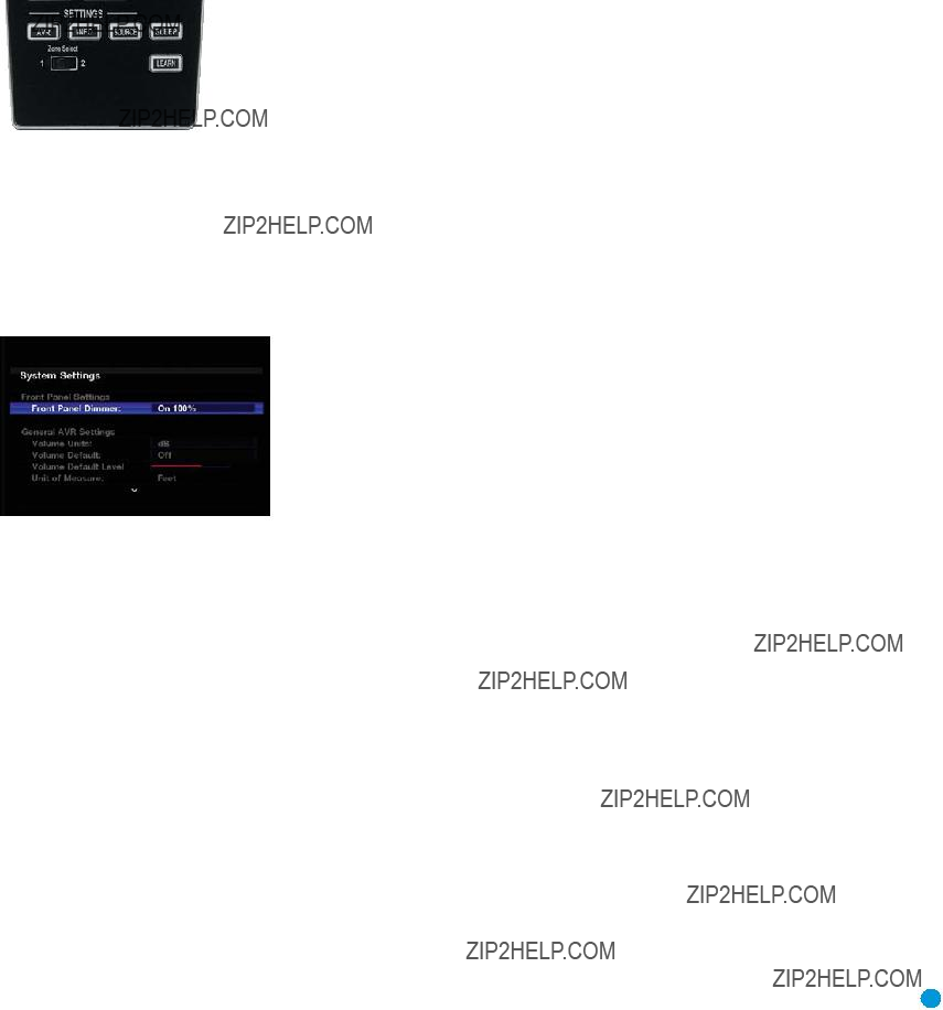
ADVANCED FUNCTIONS
section of the Speaker Setup menu to configure the remote speakers with this setting at Main Room, and return this setting to Zone 2 when you have finished.
To operate the multizone system using the main remote, slide the Zone Select Switch at the bottom of the remote to the ???2??? position (see Figure 75). To select a zone using the Zone 2 remote, press the Zone Selector, and the Zone Indicator will turn green when the remote is set to operate Zone 1, or red to operate Zone 2.
Figure 75 ??? Zone Select Switch
System Settings
The AVR 354 offers system settings that allow you to make the receiver easier to use rather than directly affecting performance. These settings may be accessed from the System Settings menu, which is selected
by pressing the AVR Button and navigating to the System line. Press the OK Button to display the System Settings menu. See Figure 76.
Figure 76 ??? Systems Settings Screen
Front Panel Dimmer: Some people find the
General AVR Settings
Volume Units: Select whether volume is displayed in the conventional decibel scale or on a numeric scale from 0 to 100. When the decibel scale is used, 0dB is the maximum volume, with lower volumes measured as negative values.
Volume Default and Volume Default Level: These two settings are used together to program a volume level the AVR will always switch to when turned on. This feature avoids discomfort for listeners in case the last user turned the volume very high.
Turn Volume Default on, and then set the Volume Default Level to the desired
Unit of Measure: This setting only affects the
iPod Charging: When The Bridge II is connected and an iPod is docked, the device???s battery charges as long as the AVR is powered on. When this setting is turned on, the device will continue to charge after the AVR has been powered down to Standby mode.
Language: Select the preferred language for the AVR???s
menus and displays: English, French, Spanish or German.
HDMI Audio to TV: This setting determines whether audio signals received through any of the HDMI Inputs are passed through the HDMI Output to the video display. In normal operation, leave this setting Off, as audio will be played through the AVR rather than the video display???s
Resolution to Display: This setting reflects the video output resolution. See page 38 in the Initial Setup section for more information.
Menu Appearance
OSD Transparency: This setting allows you to select whether video programs will be visible when the menu system is in use. Select Normal for a
Volume Status Messages: When the AVR is turned on, the volume is adjusted or the source is changed, or if a change in the input signal is detected, a status message will be displayed on screen. Use this setting to select how long the message remains visible. The setting varies from 2 to 10 seconds, with a default of 3 seconds.
Menus: Some menu settings only remain in effect during the current listening session, including the settings in the Surround Modes, Video Modes and Audio Effects menus. This setting governs how long these menus will remain visible after your last adjustment, varying from 2 to 10 seconds, with a default of 3 seconds.
Setup and
a timeout period of 5, 10 or 15 (the default) minutes, or no timeout, which leaves the menus on screen until you manually clear them. We recommend setting some timeout period to avoid the possibility of
55

ADVANCED FUNCTIONS
Screen Saver: Use this setting to program a timeout period for no activity (with no menus displayed) before the AVR???s
Advanced Remote Control Functions
The AVR 354 remote control not only operates the AVR 354, but it also serves as a universal remote that may be programmed to operate many other home theater components, as described in the Installation section. Each time you select one of your other components, the AVR remote switches to the control functions for that component. Since many buttons have unique functions for each component, refer to the Function List (Table A13 in the appendix) for assistance in operating your other com- ponents. The function of each button will not necessarily correspond to the label printed on the button.
The AVR 354 remote???s
To program
1.Press and hold the Source Selector (or AVR selector) for the main device the remote will be operating. The Source Selector will light, go dark and then light up again, indicating the remote is in Program mode and that you may release the button.
2.Select the type of
a)To program channel control
b)To program transport control
3.Press the Source Selector for the device whose channel or transport controls you would like to be active while operating the device you selected in the first step. The Source Selector will flash to confirm the programming.
For example, if you wish to watch your TV while changing channels using your cable box, first press and hold the TV Button until it lights. Then press the Channel Up Button, followed by the CBL/SAT Button.
To undo
NOTE: The remote always allows
Activities (Macros)
Activities are used to program sequences of up to 19 commands that are executed with a single button press. Activities are well suited for power on and off commands, or to send out a favorite multidigit channel number with one button press, or to have the ability to send out a code sequence to control another device while the remote is operating one device, but with more flexibility than the
NOTE: Use caution when programming complicated activities. It isn???t possible to program a pause or delay before sending com- mands after Power On, and the component may not be ready to respond to commands instantaneously after powering on.
To program, or ???record??? an activity, follow these steps:
1.To enter Program mode, simultaneously press and hold the Activity Button and the Alphanumeric Key or AVR Power On Button to which the activity will be assigned.
2.Press the Input (or AVR) Selector for each device before you enter commands to be transmitted to that device. This step counts as one of the 19 commands allowed for each macro.
3.For the Power On command, press the AVR or Device Power On Button as appropriate.
4.Press the AVR or Device Power Off Button to program the Power Off command.
5.Press the Activity Button to end the programming process, and the last Source Selector (or the AVR Settings Button) will flash three times to indicate that the activity has been programmed.
It isn???t possible to ???edit??? a command within a macro. However, you may erase the macro as follows:
1.Simultaneously press and hold the Activity Button and the Numeric Key or AVR Power On Button assigned to the activity until the Source Selector or AVR Settings Button lights.
2.Press the Activity Button to erase the macro.
Learning
If you have programmed a product???s codes into the remote and find that some functions are missing, the AVR 354 remote may ???learn??? individual codes if you have the product???s original remote. See page 31 for instructions on learning remote codes.
Resetting the Remote
To reset the remote to its factory defaults, simultaneously press and hold the TV Source Selector and the ???0??? Alphanumeric Key. When the TV Button
56

ADVANCED FUNCTIONS
Processor Reset
There may be instances when you wish to fully reset the AVR 354 to its factory defaults, or the unit may behave erratically after a power surge.
To correct erratic behavior, first try turning the Master Power Switch off and unplugging the AC power cord for at least three minutes. Plug the cord back in and turn the receiver back on. If this doesn???t help, try a system reset.
NOTES:
???A system reset erases all user configurations, including video resolution, speaker and level settings, and tuner presets. After a reset, you will need to reenter all of these settings.
???The
To reset the AVR 354, place the receiver in Standby mode (press the
Follow the directions in the note on page 34 to restore the picture if necessary.
If the receiver still does not function correctly after a processor reset, contact an authorized Harman Kardon service center for assistance. Authorized service centers may be located by visiting the Web site at www.harmankardon.com.
Memory
If the AVR 354 is unplugged or experiences a power outage, it will retain user settings for up to four weeks.
57

TROUBLESHOOTING GUIDE
Unable to activate Program mode on remote
???Source Selector not held for at least 3 seconds
???The selector will light as you initially press it, and go dark as you hold it down. Wait at least 3 seconds for the selector to light
up again.
Additional information on troubleshooting possible problems with your AVR 354, or

APPENDIX
Appendix ??? Default settings, worksheets, remote product codes
Table A1 ??? Recommended Source Component Connections
*Make this connection only when using the TV source for a
Table A2 ??? Source Setting Defaults
59

APPENDIX
Table A3 ??? Speaker/Channel Setting Defaults
*Note: The
Table A4 ??? Delay Setting Defaults
APPENDIX
Table A5 ??? Source Settings
Table A6 ??? Audio Effects Settings
Table A7 ??? Video Modes Settings
*Note: These settings are only available when the Video Mode is set to Custom.
**Note: These settings are only displayed when Advanced Video Settings is selected.
61

APPENDIX
Table A8 ??? Surround Modes
*Note: These settings are only available when Dolby Pro Logic II or IIx Music mode has been selected. Access these settings by selecting the Edit option.
Table A9 ??? Remote Control Codes
Table A10 ??? System Settings

Table A12 ??? Surround Modes
63

APPENDIX

65

APPENDIX
Copyright (c) 2003 by Bitstream, Inc. All Rights Reserved. Bitstream Vera is a trademark of Bitstream, Inc.
Permission is hereby granted, free of charge, to any person obtaining a copy of the fonts accompanying this license (???Fonts???) and associated documentation files (the ???Font Software???), to reproduce and distribute the Font Software, including without limitation the rights to use, copy, merge, publish, distribute, and/or sell copies of the Font Software, and to permit persons to whom the Font Software is furnished to do so, subject to the following conditions:
The above copyright and trademark notices and this permission notice shall be included in all copies of one or more of the Font Software typefaces.
The Font Software may be modified, altered, or added to, and in particular the designs of glyphs or characters in the Fonts may be modified and additional glyphs or characters may be added to the Fonts, only if the fonts are renamed to names not containing either the words ???Bitstream??? or the word ???Vera???.
This License becomes null and void to the extent applicable to Fonts or Font Software that has been modified and is distributed under the ???Bitstream Vera??? names.
The Font Software may be sold as part of a larger software package but no copy of one or more of the Font Software typefaces may be sold by itself.
THE FONT SOFTWARE IS PROVIDED ???AS IS???, WITHOUT WARRANTY OF ANY KIND, EXPRESS OR IMPLIED, INCLUDING BUT NOT LIMITED TO ANY WARRANTIES OF MERCHANTABILITY,
FITNESS FOR A PARTICULAR PURPOSE AND NONINFRINGEMENT OF COPYRIGHT, PATENT, TRADEMARK, OR OTHER RIGHT. IN NO EVENT SHALL BITSTREAM OR THE GNOME FOUNDATION
BE LIABLE FOR ANY CLAIM, DAMAGES OR OTHER LIABILITY, INCLUDING ANY GENERAL, SPECIAL, INDIRECT, INCIDENTAL, OR CONSEQUENTIAL DAMAGES, WHETHER IN AN ACTION OF
CONTRACT, TORT OR OTHERWISE, ARISING FROM, OUT OF THE USE OR INABILITY TO USE THE FONT SOFTWARE OR FROM OTHER DEALINGS IN THE FONT SOFTWARE.
Except as contained in this notice, the names of Gnome, the Gnome Foundation, and Bitstream Inc., shall not be used in advertising or otherwise to promote the sale, use or other dealings in this Font Software without prior written authorization from the Gnome Foundation or Bitstream Inc., respectively. For further information, contact: fonts at gnome dot org.
This product incorporates copyright protection technology that is protected by method claims of certain U.S. patents and other intellectual property rights owned by Macrovision Corporation and other rights owners. Use of this copyright protection technology must be authorized by Macrovision Corporation, and is intended for home and other limited viewing uses only unless otherwise authorized by Macrovision Corporation. Reverse engineering or disassembly is prohibited.

APPENDIX
Refer to the numbered buttons in Figure 77 when using the Function List.
Figure 77 ??? Remote Control Function List Reference
41 42 43
67

APPENDIX
Table A13 ??? Remote Control Function List

APPENDIX
Table A13 ??? continued
69

APPENDIX
Refer to Tables A14 through A24 when programming the codes for your components into the remote.
Table A14 ??? Remote Control Product Codes: TV
APPENDIX
Table A14 ??? continued
Table A15 ??? Remote Control Product Codes:
Table A16 ??? Remote Control Product Codes:
71

APPENDIX
Table A16 ??? continued
Table A17 ??? Remote Control Product Codes:

APPENDIX
Table A17 ??? continued
Table A18 ??? Remote Control Product Codes: DVD
Table A19 ??? Remote Control Product Codes: SAT
73

APPENDIX
Table A21 ??? Remote Control Product Codes: CBL
Table A22 ??? Remote Control Product Codes:
Table A23 ??? Remote Control Product Codes:
Table A24 ??? Remote Control Product Codes: AUX- TiVo

AVR 354 TECHNICAL SPECIFICATIONS
Audio Section
Stereo Mode
Continuous Average Power (FTC)
75 Watts per channel,
@ <0.07% THD, both channels driven into 8 ohms
Power per Individual Channel
Front L & R channels: 75 Watts per channel
@ <0.07% THD,
Center channel:
75 Watts @ <0.07% THD,
Surround (L & R Side, L & R Back) channels: 75 Watts per channel
@ <0.07% THD,
Depth measurement includes knobs, buttons and terminal connections.
Height measurement includes feet and chassis.
All features and specifications are subject to change without notice.
Harman Kardon and Logic 7 are trademarks of Harman International Industries, Incorporated, registered in the United States and/or other countries. EzSet/EQ, Designed to Entertain and The Bridge II logo are trademarks of Harman International Industries, Incorporated.
iPod, iTunes and Apple are trademarks of Apple Inc., registered in the U.S. and other countries. ???Made for iPod??? means that an electronic accessory has been designed to connect specifically to iPod and has been certified by the developer to meet Apple performance standards. Apple is not responsible for the operation of this device or its compliance with safety and regulatory standards.
Audiovox is a registered trademark of Audiovox Corporation.
CEA is a registered trademark of the Consumer Electronics Association.
Cirrus Logic is a registered trademark of Cirrus Logic, Inc.
Dolby and Pro Logic are registered trademarks, and MLP Lossless is a trademark, of Dolby Laboratories.
DTS,
Faroudja DCDi Cinema is a trademark of Genesis Microchip Inc.
HDMI is a trademark or registered trademark of HDMI Licensing LLC.
SACD is a trademark of Sony Corporation.
TiVo is a registered trademark of TiVo Inc.
XM and XM Ready are registered trademarks of XM Satellite Radio.
Please register your AVR 354 at www.harmankardon.com.
NOTE: You???ll need the product???s serial number. At the same time, you can choose to be notified about new products and/or special promotions.
75

??
250 Crossways Park Drive, Woodbury, New York 11797 www.harmankardon.com
?? 2008 Harman International Industries, Incorporated. All rights reserved. Part No. CQX1A1311Z