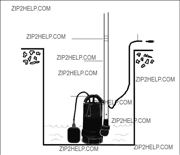
7.Carefully set the Pump in place. Do not lower or raise the Pump by its Power
Cord (1) or Discharge Pipe. (See Figure E.)
8.The Float Switch (2) automatically switches on and off at a water depth of ap- proximately 4 inches. The ON/OFF height can be manually adjusted by adjusting the Float Switch Lock. CAUTION: Do not run the Pump dry. Doing so will increase wear to the unit and possibly cause seal damage. (See Figure E.)
9.NOTE: This Pump has a built-in thermal protector for the Motor which automati- cally shuts it off to avoid overheating. After the Motor cools, it will cycle back on. Wait for the cycle to continue. Do not try to turn on the Pump manually after it has automatically shut off.
10.Connect additional Discharge Pipe as needed to direct the water discharge to the desired location. The discharge should be kept as short as possible with a mini- mum number of turns. IMPORTANT: Do not exceed the maximum lift of the Pump:
1 HP Model 93819 = 33 Feet.
1.2 HP Model 93820 = 36 Feet.
11.Connect the Power Cord & Plug (1) to its 120 volt, GFCI electrical outlet, while making sure to form a ???drip loop??? in the Power Cord. (See Figure A.)
12.When the water level exceeds approximately 4 inches the Pump will automatically turn on and run continuously until the water level falls below 4 inches at which time the Pump will automatically turn off.
13. WARNING! When shutting off power to the Pump, always shut off the electrical power to the GFCI outlet first. Then, disconnect the Pump???s Power
Cord & Plug (1) from the GFCI outlet.
INSPECTION, MAINTENANCE, AND CLEANING
1.  WARNING! Always shut off the electrical power to the GFCI outlet first. Then, disconnect the Pump???s Power Cord & Plug (1) from the GFCI outlet prior to performing any inspection, maintenance, or cleaning procedures.
2.Before each use, inspect the general condition of the Pump. Check for cracked or broken parts, damaged electrical wiring, clogged Impeller Cover, Impeller, Discharge Pipes, and any other condition that may affect safe operation. If abnormal noise or vibration occurs, have the problem corrected before further use. Do not use damaged equipment.
3.To clean the Impeller Cover and Impeller: A clogged or dirty Impeller Cover

 WARNING!
 eliminates the need for the three wire grounded power cord and grounded power supply system.
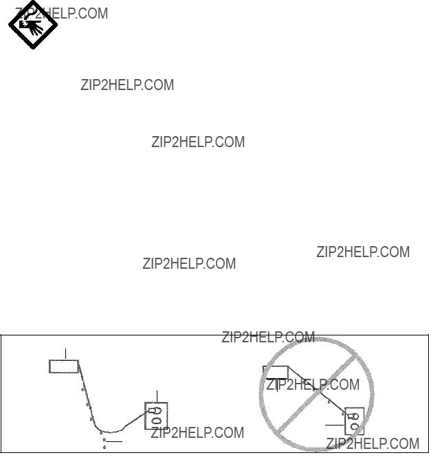
 WARNING! Always arrange a ???drip loop??? in the Power Cord connecting the Pump to a 120 volt, GFCI electrical outlet.


 WARNING!


 CAUTION! All maintenance, service, or repairs not mentioned in this manual must only be performed by a qualified service technician.
 LIMITED 90 DAY WARRANTY