Smart Phone Compatible

H.264 DVR Security System

68332 DVR Security System

When unpacking, make sure that the product is intact and undamaged. If any parts are missing or broken, please call 1-800-520-0882 as soon as possible.

Record Product???s Serial Number Here:

Note: If product has no serial number, record month and year of purchase instead.

Note: Some parts are listed and shown for illustration purposes only, and are not available individually as replacement parts.

Visit our website at: http://www.harborfreight.com

Copyright?? 2010 by Harbor Freight Tools??. All rights reserved. No portion of this manual or any artwork contained herein may be reproduced in any shape or form without the express written consent of Harbor Freight Tools. Diagrams within this manual may not be drawn proportionally. Due to continuing improvements, actual product may differ slightly from the product described herein. Tools required for assembly and service may not be included.

Specifications

B??????Specifications

1??????Safety Warnings

2?????????Grounding

4??????Introduction

4?????????Features 4?????????Setup Overview

5??????Components and Controls

5?????????Components 6?????????Remote Control 6?????????Front Panel 6?????????Back Panel

7??????Set up

7??????Cable Connections

8??????Programming Your DVR

8?????????Entering the Main Menu 9?????????Main Menu

10?????????Camera Setup - Channel Title, Position, Live Display

10?????????Color Setup - Image Brightness, Saturation, Contrast, Hue

10?????????Autoseq - Image Auto Cycle Function

10?????????Privacy Zone

11?????????Record Setup - Resolution, Quality, Audio, Record Time

SContents

11?????????Record Schedule 11?????????DVR Recording Time 12?????????Network Setup 13?????????Static Addresses 14?????????Device Management 14?????????HDD Management 15?????????Alarm Set

15?????????Email Alarm Notification

16?????????PTZ Setup (Pan/Tilt/Zoom) 16?????????Mobile

17?????????Motion Detect 18?????????System Function 18?????????Time Setup 18?????????Password 19?????????Video Setup 19?????????Language 19?????????Information 20?????????System Maintenance 20?????????Menu Lock

21??????Basic Operation

21?????????Navigating the Menu List

22??????Recorded Video Search and Playback

22?????????Video Search 23?????????Recording File Backup

24??????Playback Program

24?????????Using Playback 25?????????Playback Settings

26??????Net-Viewer Program

26?????????Installing Software 26?????????Adding DVR to Trusted Sites 26?????????Port Forwarding

27?????????Main Screen Controls 27?????????Live Mode 27?????????Log-in to Net-Viewer 28?????????Replay Mode 28?????????Controls

28?????????Setup Mode 28?????????Record 28?????????Schedule 29?????????Alarm 29?????????PTZ Control 29?????????Network 30?????????Setting 30?????????Host Information

31??????Troubleshooting

32??????Warranties

33??????Notes

Save This Manual

Keep this manual for the safety warnings and precautions, assembly, operating, inspection, maintenance and cleaning procedures. Write the product???s serial

number in the back of the manual near the assembly diagram (or month and year of purchase if product has no number). Keep this manual and the receipt in a safe and dry place for future reference.

Safety Warnings

In this manual, on the labeling, and all other information provided with this product:

This is the safety alert symbol. It is used to alert you to potential personal injury hazards. Obey all safety messages that follow this symbol to avoid possible injury or death.

DANGER indicates a hazardous situation which, if not avoided, will result in death or serious injury.

WARNING indicates a hazardous situation which, if not avoided, could result in death or serious injury.

CAUTION, used with the safety alert symbol, indicates a hazardous situation which, if not avoided, could result in minor or moderate injury.

NOTICE is used to address practices not related to personal injury.

CAUTION, without the safety alert symbol, is used to address practices not related to personal injury.

WARNING! Read all instructions.

Failure to follow all instructions listed below may result in fire, serious injury and/or DEATH.

The warnings and precautions discussed in this manual cannot cover all possible conditions and situations that may occur. It must be understood by the operator that common sense and caution are factors which cannot be built into this product, but must be supplied by the operator.

SAVE THESE INSTRUCTIONS

1.Work area safety

Keep cameras, cables and DVR our of reach of children.

2.Electrical safety

a.Power plugs must match the outlet. Never modify the plug in any way. Do not use any adapter plugs with grounded plugs. Unmodified plugs and matching outlets will reduce risk of electric shock.

b.Do not expose DVR Unit to rain or wet conditions.

c.Do not abuse the cord. Never use the cord for carrying, pulling or unplugging the unit. Keep cord away from heat, oil, sharp edges or moving parts. Damaged or entangled cords increase the risk of electric shock.

3.Service

Have your DVR serviced by a qualified repair person using only identical replacement parts. This will ensure that the safety of the unit is maintained.

DVR-Camera Kit Safety Warnings

4.Maintain labels and nameplates on the unit. These carry important safety information. If unreadable or missing, contact Harbor Freight Tools for a replacement.

5.People with pacemakers should consult their physician(s) before use. Electromagnetic fields in close proximity to heart pacemaker could cause pacemaker interference or pacemaker failure. In addition, people with pacemakers should properly maintain and inspect to avoid electrical shock.

6.WARNING: Handling the cord on this product will expose you to lead, a chemical known to the State of California to cause cancer, and birth defects or other reproductive harm. Wash hands after handling. (California Health & Safety Code ?? 25249.5, et seq.)

Save these instructions.

Grounding

To prevent electric shock and death from

incorrect grounding wire connection:

Check with a qualified electrician if you are in doubt as to whether the outlet is properly grounded. Do not modify the power cord plug provided with the device. Never remove the grounding prong from the plug. Do not use the device if the power cord or plug is damaged. If damaged, have it repaired by a service facility before use. If the plug will not fit the outlet, have a proper outlet installed by a qualified electrician.

Grounded Devices: Devices

with Three Prong Plugs

Double Insulated Devices: Devices with Two Prong Plugs

Outlets for 2-Prong Plug

1.Devices marked ???Double Insulated??? do not require grounding. They have a special double insulation system which satisfies OSHA requirements

and complies with the applicable standards of Underwriters Laboratories, Inc., the Canadian Standard Association, and the National Electrical Code. (See Outlets for 2-Prong Plug.)

2.Double insulated devices may be used in either of the 120 volt outlets shown in the preceding illustration. (See Outlets for 2-Prong Plug.)

3-Prong Plug and Outlet

1.Devices marked with ???Grounding Required??? have a three wire cord and three prong grounding plug. The plug must be connected to a properly grounded outlet. If the device should electrically malfunction or break down, grounding provides a low resistance path to carry electricity away from the user, reducing the risk of electric shock. (See 3-Prong Plug and Outlet.)

2.The grounding prong in the plug is connected through the green wire inside the cord to the grounding system in the device. The green wire in the cord must be

the only wire connected to the device???s grounding system and must never be attached to an electrically ???live??? terminal. (See 3-Prong Plug and Outlet.)

3.The device must be plugged into an appropriate outlet, properly installed and grounded in accordance with all codes and ordinances. The plug and

outlet should look like those in the preceding illustration. (See 3-Prong Plug and Outlet.)

Extension Cords

1.Grounded devices require a three wire extension cord. Double Insulated devices can use

either a two or three wire extension cord.

2.As the distance from the supply outlet increases, you must use a heavier gauge extension cord. Using extension cords with inadequately sized wire causes a serious drop in voltage, resulting in loss of power and possible device damage.

(See Table A.)

3.The smaller the gauge number of the wire, the greater the capacity of the cord. For example, a 14 gauge cord can carry a higher current than a 16 gauge cord. (See Table A.)

4.When using more than one extension cord to make up the total length, make sure each cord contains at least the minimum wire size required. (See Table A.)

5.If you are using one extension cord for more than one device, add the nameplate amperes and use the sum to determine the required minimum cord size. (See Table A.)

6.If you are using an extension cord outdoors, make sure it is marked with the suffix ???W-A??? (???W??? in

Canada) to indicate it is acceptable for outdoor use.

7.Make sure the extension cord is properly wired and in good electrical condition. Always replace a damaged extension cord or have it repaired by a qualified electrician before using it.

8.Protect the extension cords from sharp objects,

excessive heat, and damp or wet areas.

RECOMMENDED MINIMUM WIRE

GAUGE FOR EXTENSION CORDS*

(120/240 VOLT)

150% of the rated amperes.

Symbology

n0 xxxx/min. No Load Revolutions per Minute (RPM)

Introduction

Features

This unit is equipped with the following features:

???Real time monitoring - Supports real time surveillance via Monitor

???Save Recordings - DVR saves real-time recorded images to HDD

???Backup Recordings - Supports DVR backup via USB flash drive and hard drive

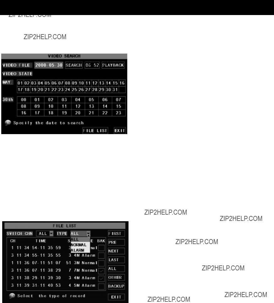
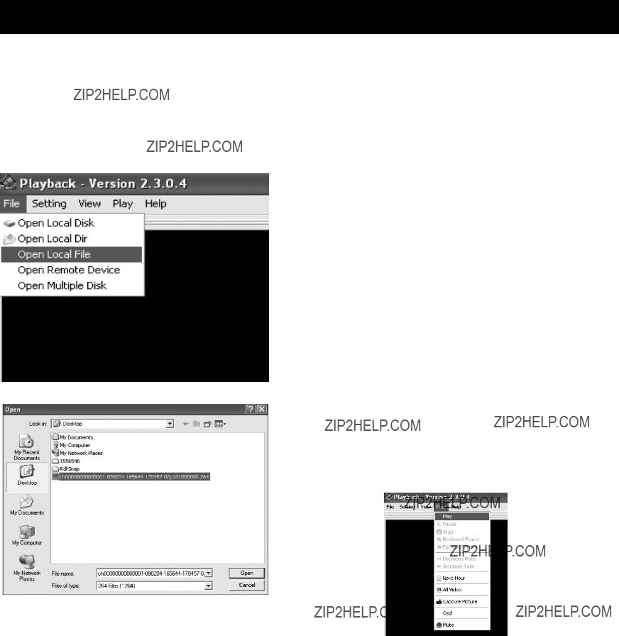
???Playback Recordings - Supports DVR single CH and multiple CH playback of recorded files

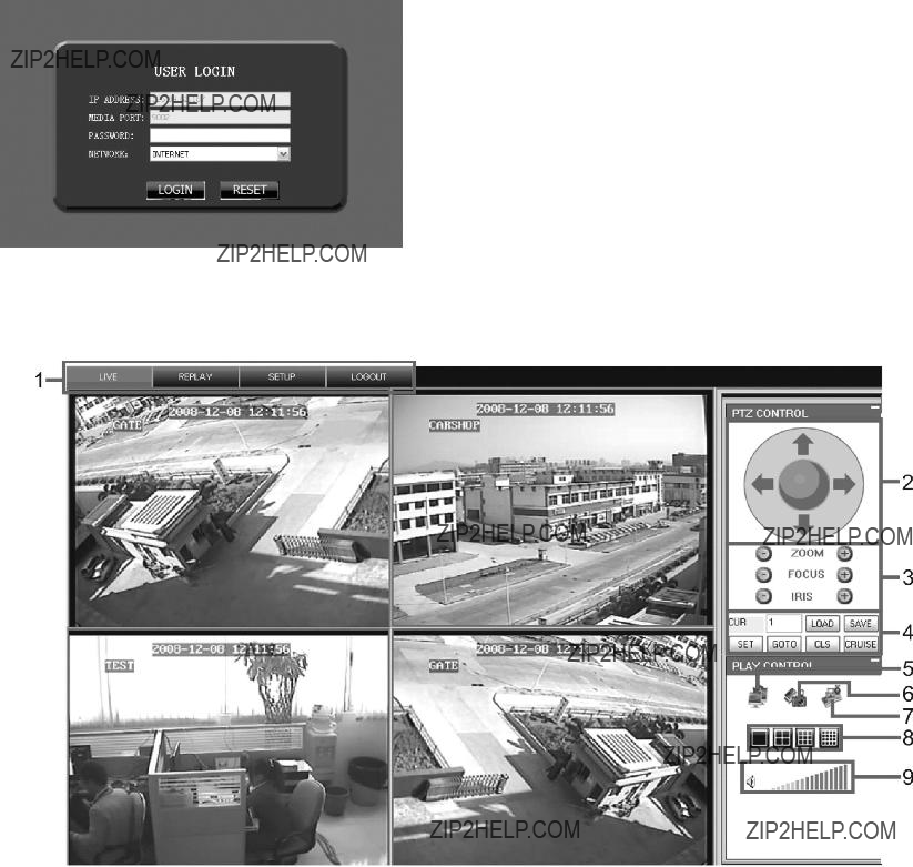
???Network operation - Supports remote surveillance by multiple users simultaneously

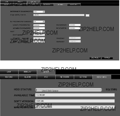
???Alarm Setting - Supports HDD & video input alarm management

???Mouse Operation - Supports Mouse operation for faster menu navigation.

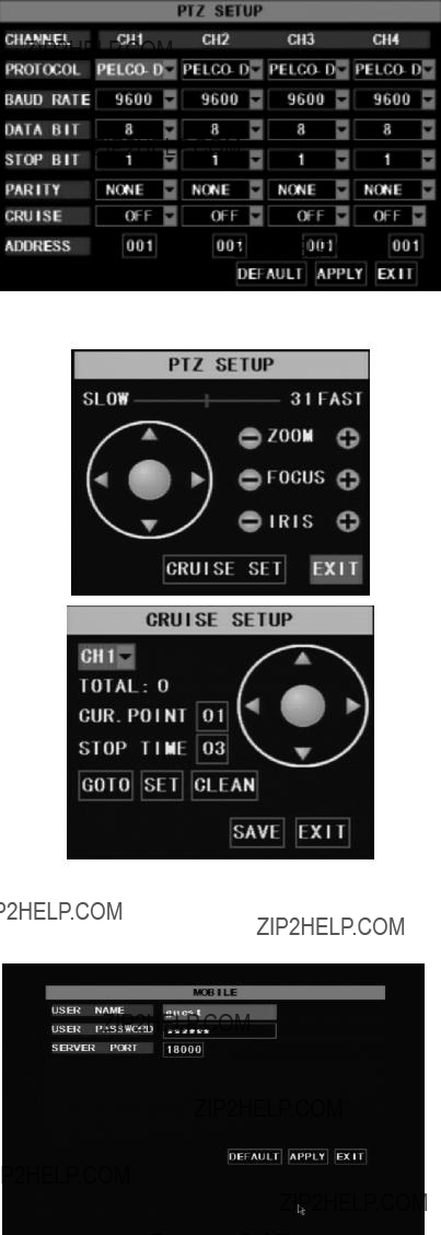
???PTZ Control - Supports PTZ (Pan/Tilt/Zoom) camera operations through RS-485 port.

???H.264 video compression format - Supports D1, HD1, and CIF resolution

???Records 9 levels of quality

???Over 2500 hrs of recording capacity (at lowest setting)

???ADPCM audio compression format

???Windows Graphical interface

???BNC video out ports

???Supports remote live viewing via 3G mobile networks

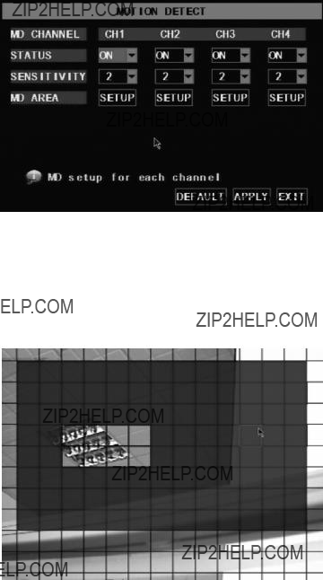
???Supports sending email alerts when motion is detected by system

???Triplex functionality (recording, playback and net transmitting at the same time)

???Supports USB mouse, infrared remote control operation

???Rear USB 2.0 ports for backup, upgrade and mouse operation

???Supports Double Encode bit network transmission

???Video package time is adjustable

???Multiple alarm record modes

???Multiple languages OSD (On Screen Display)

???Supports auto maintenance

Setup Overview

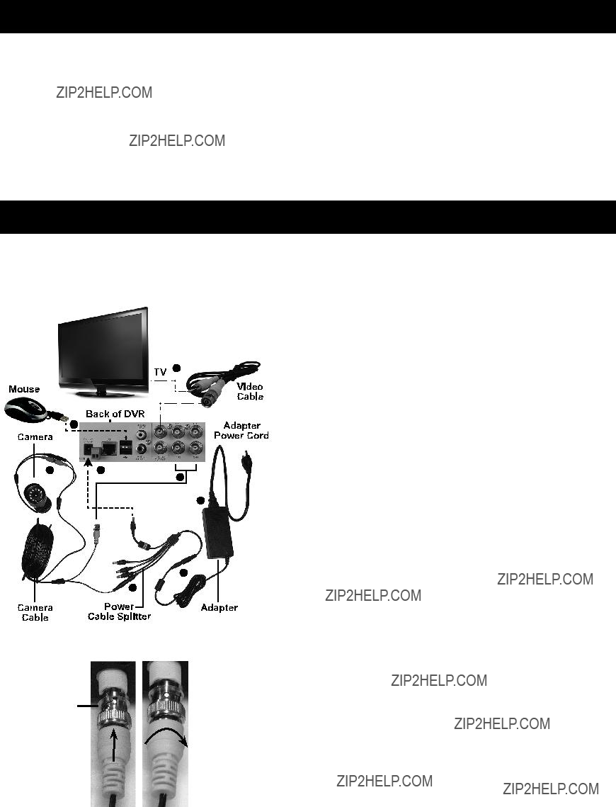
This unit can be set up in several different configurations. The simplest is with a TV monitor. For set up through the internet there are specific software requirements and you will need to have an understanding of your router, your computer and your internet connection settings, as well as port forwarding knowledge. Following are the possible set up options.

1.DVR with a TV monitor (sold separately) - This is the simplest set up that allows you to adjust all the settings, view and record live images and play back any recordings. You do not have to have a computer or internet capabilities with this set up.

2.DVR with a computer and a TV monitor (both sold separately) - This set up allows you to view recorded files on a computer connected to the unit. You can record when you view the DVR over the internet.

3.DVR and a computer, connected to the same router and accessed through your web browser (computer and router sold separately) - This set up allows you to adjust all the settings, view and record live images, and play back any recordings through your web browser. You will first need a TV monitor to set up the system. This option may not function with all web browsers.

4.Remote access through your internet service - This arrangement allows remote access to the DVR through the internet or your internet capable mobile device. You will need to have the unit already set up as in the previous paragraph, and have set up knowledge of port forwarding and your router???s external IP address in order to set up this configuration.

Components and Controls

Components

Video Cable

Adapter

Adapter

Power

Cord

Four Cameras

Camera Cables

Remote Control

Cable Splitter

DVR

Front Panel

Set up

IMPORTANT: Before mounting any of the cameras, test the unit by hooking up all the connections as shown below, and testing all the features to insure the unit is working properly. There are two 6mm cameras for longer range, and two 3.6mm cameras for wider angle, shorter range, viewing. Test the cameras for the best location before installing. Each camera is labeled on the side of the unit.

1.Designate a work area that is clean and well-lit. The work area must not allow access by children or pets to prevent distraction and injury.

2.Route the power cord and all cabling along a safe route without creating a tripping hazard or exposing the cord and cables to possible damage.

3.Use a surge protector (sold separately) to help guard against electrical power fluctuations.

Cable Connections

You will initially need to connect the DVR to a TV monitor in order to adjust the settings, regardless of your final intended set up.

BNC

Connector

To connect the camera and power components to the DVR:

1.Attach the Adapter Power Cord to the Adapter.

2.Attach the Power Adapter Cable to the single end of the Cable Splitter.

3. Attach the connector marked ???DVR Power??? to the Power Input Jack on the back of the DVR.

4.Working with one Camera Cable, attach the yellow video BNC Connector (the largest connector on the

cable) to one of the camera connections on the back of the DVR (CH1, CH2, CH3, or CH4).

5. Attach the black power connector at the BNC end of the same cable to one of the remaining Cable Splitter connectors.

6. Attach the connectors at the other end of the Camera Cable to the same color connectors of one of the Cameras.

Repeat steps 4 through 6 for each of the other three Cameras and Camera Cables.

7.Plug the Mouse into one of the USB ports.

8.Attach the BNC connector of the Video Cable to one of the video output ports on the back of the DVR, then attach

the other end of the cable to the video port of the TV. Plug the TV into a wall outlet. The unit will power up.

Programming Your DVR

System Initialization

After connecting the cables and the power adapter, the system will boot-up and start initializing.

Main Interface

After system initialization, the system will display the main interface (shown at left before video input status has been entered). Once the video inputs are set up, the interface will display live images from the cameras.

DVR Controls

The DVR can be controlled using the buttons on the front panel of the DVR, the Remote Control, or the Mouse.

Refer to the charts on page 6 for Front

Panel or Remote Control operation.

Use the following for Mouse operation:

Entering the Main Menu

After finishing system initialization, enter the Main Menu. To enter the Main Menu, press the Menu button on the DVR or the remote control, or right-click the mouse button to bring up the menu list then left-click MAIN MENU.

Menu Main

Camera

Record

Network

Search

Devices

System

Color Setup

AutoSeq

Schedule

Search

Playback

Main Menu

The Main Menu is for setting up the DVR and cameras for recording, playback network and other access. You can also set system function settings, such as the time, user password, Audio/Video settings, language, system information, and system maintenance.

Note: When setting up or making changes to the program settings, you must press APPLY to have the settings take affect.

Note: To save changes, you must press APPLY.

Camera Setup - Channel Title, Position, Live Display

In the Main Menu select CAMERA. The Display Setup menu will display (shown at left). You can edit the name of each channel (camera) and change the position where the name is displayed. Set up whether each channel can be previewed or not under Live display and/or Recording mode.

Note: The name of each channel supports up to eight characters.

PRIVACY ZONE

Color Setup - Image Brightness, Saturation, Contrast, Hue

1.In the Display Setup submenu, select SETUP under the COLOR column for one camera. The color setup sub-menu will display (shown at left).

2.Adjust the hue, brightness, contrast and saturation, then click APPLY. You will be prompted to save, click OK, then EXIT.

3.Repeat steps 1 and 2 for each camera.

Note: If you want to cancel the modification, click EXIT to exit the menu.

4. Click DEFAULT to return to default values.

Autoseq - Image Auto Cycle Function

In the Display Setup submenu, select AUTOSEQ to enter the auto cycle submenu, (shown left). In the auto cycle function, the system will automatically rotate the video images from a full screen image of each channel (CH1, CH2, CH3 and CH4),

then Quad (all channels), then repeat. Default rotation time is 5 seconds.

The time range is adjustable from off to 10 seconds.

Note: After selecting APPLY in AUTOSEQ, you can exit the menu and click PAUSE on the front panel or remote control, while in live playback, to activate this function.

Privacy Zone

In the AUTOSEQ submenu, select PRIVACY ZONE to select 1 to 4 areas of the screen to block from view. Using the mouse, click and drag to create the size of the area to block, then click the box and drag it to the desired location. A black box will display on the screen and block that area from viewing and recording.

Note: To save changes, you must press APPLY.

Record Setup - Resolution, Quality, Audio, Record Time

In the Main Menu select RECORD to enter the Record Setup submenu (shown at left).

The Record Setup menu allows you set the recording status (on/off) of each channel, the image resolution and quality, and whether audio is on or off. This menu also allows you to select recording mode (recording as soon as the DVR has booted up vs. scheduled recording), and recording file length.

Once a channel is set to ???on???, the channel can record, if it is set to ???off???, the video from the channel will not be recorded. Resolution options are D1, HD1 and CIF; and Quality options are Best, Good and Normal

- lower quality means a smaller recorded file size.

Note: In NTSC format, pixel resolutions are:

When Audio is set to ???On???, the system will also record audio from the microphone (sold separately) attached to the audio input, and will have audio output on playback mode; if it is set to ???off???, you can not record audio and will have no audio output available on playback mode.

Record Schedule

Sample Recording Hours

To record 24 hours a day, set the Rec Mode to ALWAYS. To record on motion or a set schedule, select Time Schedule Record and select the SCHEDULE option. The Schedule submenu will display (shown at left): Recording options include CH-1, CH-2, CH-3,

CH-4 or All channels. Click the desired option.

To set up weekly schedules, select the box of the recording status you want (ALARM (motion detected), GENERAL, or NO RECORD) and then click on each box in the schedule time line that you want this method to apply to. You can use the [From ??? To] pull-down menus at the bottom of the screen and the COPY button to copy settings from one day to another day. After completing the schedule, activate it by clicking APPLY.

Select DEFAULT to restore the system defaults.

Note: Each box in the SCHEDULE sub-menu represents one hour in a 24 hour cycle. The background color stands for no recording, ???Red??? stands for alarm or motion detected recording, ???Green??? stands for general or normal recording and ???Black??? stands for no recording.

DVR Recording Time

The DVR recording time capacity varies depending on the quality setting, the resolution option

and the number of cameras recording at the same time. The chart at left shows examples of maximum recording times at different settings.

Note: To save changes, you must press APPLY.

Network Setup

In the Main Menu, select NETWORK SETUP to enter the Network Setup menu. Select network Type - such as DHCP, PPPOE, or static allocation. (See following sections for network type information.) Enter Port information and Web Port (Media port 9000 and web port 80 by default).

Note: When selecting DHCP the router will allocate DVR IP address automatically after you exit the menu. Write down the addresses assigned and then switch to static and re-enter the addresses so the router does not change them later.

PPPoE

When selecting PPPoE, input the user name and password provided by your internet service provider and enter the media port and web port information.

Note: To save changes, you must press APPLY.

Static Addresses

When selecting static allocation, you will need to set up the network settings on the DVR to match the settings of the router that you attach to the DVR. To find the router settings, working on a PC computer attached to the same router as the DVR, go to START (lower left of screen), click Run, type ???cmd??? then ENTER to bring up a command prompt. Type ???ipconfig??? then ENTER, to access the router settings. (See image, top left). Write down the gateway and subnet mask numbers, then close the window.

In the DVR Main Menu, select [NETWORK] to enter the NETWORK SETUP MENU. Go to TYPE and select

STATIC. For the DVR???s IP address enter the same first

3 sets of numbers as the router???s gateway and select a fourth set of numbers that is different than any other device attached to the same router. If the IP address of your computer in the ipconfig was a single or two digit number, enter any three digit number. If the computer IP address ends with a number in the 100s, enter a number in the 200???s. After you enter the addresses click APPLY.

At the bottom of the NETWORK SETUP window there is an option to setup the DVR to be accessed through a DDNS service. When you click on the DDNS button it brings up the window displayed as shown bottom left. You can access the DVR through a static or dynamic IP address; however a dynamic address can change from time to time. How often depends

on your service provider. When it changes you need to find out what the new IP address is and re-enter it. To avoid this, get a static IP address from your

service provider so that you do not have to re-enter the address when it changes. Another solution would to use a dynamic domain name service to get a domain name that can be linked to your dynamic address.

There are services that allow you to get a domain name, user name, and password. You can then enter Your dynamic domain name into an Internet Explorer browser instead of an IP address and be directed to whatever the current dynamic IP address is, so that you can always access the DVR by entering the same address.

Note: To save changes, you must press APPLY.

Device Management

Options in device management includes hard drive, External Alarm, PTZ control, Mobile Phone Monitoring, and Motion Detection.

HDD Management

In the Main Menu???Device ??? HDD] to enter [HDD

Management] menu. When you install a HDD, the system will automatically detect whether the HDD is formatted.

Menu Descriptions

HHD STATUS: Indicates Hard Drive status. Displays ???No Disk???, ???Not Format??? if Hard Drive needs formatting, and ???Normal??? if Hard Drive is formatted and ready to use.

TOTAL SPACE: Indicates total space available on Hard Drive.

FREE SPACE: Indicates unused space available on the Hard Drive.

USABLE REC TIME: Based on current image detail/ quality and frame rate, system will show you how much recording time you have left on the Hard Drive.

OVERWRITE: If you select ???on??? the system will automatically overwrite the oldest recordings once the hard drive is full; if you select ???off???, recording will stop once the hard drive is full.

HDD FORMAT: You use this option to format the hard drive, you can not record files to the hard drive until

it has been formatted. Click [Format HDD] button to start formatting. When selecting [Format HDD] option the system will prompt you ??? ???Format HDD will loss all the data, do you confirm???? ; click ???OK???, system will prompt you ??? ???Is formatting?????? and ???successful format???; and then system will restart automatically.

USB FORMAT: Use this option to format USB devices.

Note: To save changes, you must press APPLY.

Alarm Set

Click [Main Menu???Device ??? Alarm] to enter into

[Alarm setup] menu to setup Alarm warnings.

HDD LOSS: Options are ???ON??? and ???OFF???. If you select ON there will be a buzzer sound and ???H??? sign on screen when the HDD is not detected or not formatted. If the function is set to OFF, there is only ???H??? sign to indicate HDD not found, but no alarm sound when HDD not found or not formatted.

HDD SPACE: Options are ???ON??? and ???OFF???. When the alarm function is ON, there are alarm sounds when the HDD is running out of space; when the function is OFF, there are no alarm sounds.

VIDEO LOSS: Options are ???ON??? and ???OFF???. When the function is ON, system will issue alarm sound and display video loss on the preview interface; when the function is OFF, system will have no alarm sound, but the preview interface will display video loss.

Email Alarm Notification

This option sends a notice to an email account when the motion alarm is triggered. Click the [Email setup] menu to enter the sub menu. Check email box and set up the address.

When ON is selected, you are prompted to enter the email information. Consult your email provider for settings for this menu if needed.

Note: Once this option is set up, be sure to clear the received images from your email account regularly to avoid overloading your email account.

Note: To save changes, you must press APPLY.

PTZ Setup (Pan/Tilt/Zoom)

(PTZ cameras not included)

Click [Main Menu???Device??? PTZ Setup] to enter the PTZ Setup menu.

Select the channel you want to control and set PTZ protocol (Pelco-D or Pelco-P), Baud Rate (1200, 2400, 4800, 9600), Stop bit (1, 2), Parity Check (None,

Odd, Even Mark Space), and Address Code.

Note: The above mentioned channel settings must match the settings of the PTZ camera.

Set CRUISE to ON to enter the sub menus that adjust the individual camera settings.

Click Z+&Z- keys to zoom In or out, click F+&F- keys to control camera focus and click I+&I- to adjust iris.

CRUISE SETUP

Click CRUISE SET to open the auto cruise function window if you want to adjust the cruise function. The system default is ON.

CH#: Select the channel number with the PTZ camera

TOTAL: Enter presetting bit quantity.

CUR POINT: System has default starting (current) cruise point as 01. You can use this option to set additional cruise points.

STOP TIME: Adjust the pause time at each stop.

GOTO: Select this option to go to specific preset points.

SET: Saves the preset point. After setting channel and setting the position by adjusting PTZ direction key click SET to setup the pre-set point. Please note you need to click SAVE to finish the setup successfully. If you want to combine Zoom, Iris, Focus and direction keys into the pre-set setting, return to previous menu to add additional settings, and then enter into Cruise Set again and click SET and SAVE to make sure your setting is setup successfully.

CLEAN: Removes settings.

Note: This DVR model supports up to 100 pre- set points. But actual quantities may be restricted by the PTZ camera you are using.

Mobile

Click [Main menu???Device???Mobile] to enter into [Mobile] menu.

USER NAME: Enter the user name of the DVR.

USER PASSWORD: Enter the user password of the DVR.

SERVER PORT: Enter the mobile monitoring port. Setting range is between 1024 and 65535.

Note: Connect the DVR to the Internet before setting the DVR port number and the server port number. Consult your mobile provider for additional information.

Note: To save changes, you must press APPLY.

Motion Detect

Click [Main???Device???Motion] to enter into the MOTION

DETECT menu to setup motion detection recording.

STATUS: Turn ON or OFF motion detection for each channel.

SENSITIVITY: Set each channel???s sensitivity level of motion detection from 1 to 4

with 4 being the most sensitive.

MD AREA: This option allows you select the area you want to be sensitive to motion. A new window displays with a grid separated into a 13 by 10 block area. Select areas in red where motion detection is desired. When any object moves into the motion detection area, (the red areas of the grid) recording will be triggered. In the shaded area the motion detection is off.

Note: To save changes, you must press APPLY.

System Function

The [System] Menu includes sub-menus for Time Set, User Password, Audio/Video Setting, Language select, System Info and System Maintenance. After entering into the [System], you can configure the system to meet your needs.

Time Setup

Click [Main Menu???System???Date/Time] to enter the time setup menu. Use this menu to modify the system date, time, date/time format and time zone, and also setup DST (daylight savings time) status and mode.

Password

Click [Main Menu???System???User Password] to enter the Password Setup menu. This option allows you set the device ID for the DVR and set the system password if you want to use one. The new passwords will be available after clicking APPLY.

When you set Password Enabled to ???ON???, you can setup a user password and administrator password respectively. The password supports up to 6 characters.

Note: To save changes, you must press APPLY.

Video Setup

Click [Main Menu???System???VIDEO] to setup

Video, here you can set Camera system to

PAL, or NTSC. In the USA use NTSC.

You can also set the resolution for the VGA video out port.

Your options are 800x600, or 1024x768, or 1280x1024.

Note: This item does not have a VGA video out port.

Language

Click [Main Menu???System???Language Select] to enter the Language Select menu. Select the language then click APPLY. The selection will be available after system Auto restarts.

Note: This option is available only when the DVR comes with Multiple language OSD.

Information

Click [Main Menu??? System???System Information] to enter the System Information menu. View system info, including Device type, Software (firmware) version and

MAC address.

Note: To save changes, you must press APPLY.

System Maintenance

Click [Main Menu??? System???System Maintenance] to enter the System Maintenance menu. This option allows you reset the DVR to factory default settings, update system software (firmware),

and set system auto-maintenance.

When opening auto-maintain function, you can setup system to restart regularly.

Menu Lock

As a system safety feature you can click [Menu Lock] menu to lock menu when leaving the DVR. If you want to login to the DVR, you would input the device code and password.

Note: The user only has the authority to search recordings, but the Administrator has full authority over Main Menu operations.

Basic Operation

Once you have set up your DVR, it will run based on the programmed schedule.

You can view and change functions through the Menu List.

Following is a description of the menu options.

PIP (picture-in-picture) and DIGITAL ZOOM are only available through the menu list as described below.

Navigating the Menu List

You can enter and navigate the Menu List with the Buttons on the DVR, the remote or the Mouse.

To navigate using the mouse:

To navigate using the remote:

???Press SELECT to display the Menu List.

???Press UP, DOWN, RIGHT or LEFT to move through the list.

???Press SELECT to select an item on the list.

MAIN MENU - Select to edit and/or view your settings and system set up.

VIDEO SEARCH - Select to search, play and/or backup recordings.

PTZ - Select to control the pan/tilt/zoom function (cameras with this function are not included).

START RECORD - Select to manually begin recording. Note: if you have recording already

scheduled, you can override the motion detect setting, or the no record setting, by choosing this function.

STOP RECORD - Select to stop recording.

START CRUISE - Select to begin the PTZ cruise function set up in the setup menu (cameras with this function are not included).

START AUTOSEQ - Select to begin an automatic cycling of the camera displays.

PIP MODE - Select to enter picture-in-picture mode. Choose 1x1 to open one extra window, or 1x2 to open two windows. With the mouse, left click on any window to cycle through the channels and display a different channel.

DIGITAL ZOOM - Select to zoom in on a single channel. Digital Zoom will only be visible on the Menu List when one of the cameras is set to full screen, and can only be set up using the mouse. Select Autoseq mode then re-display the Menu List to view the Digital Zoom function at the bottom of the list if it is not already displayed. Select Digital Zoom. Using the mouse, left click, hold and drag, to highlight the area to zoom in on. Release when you have highlighted the area that you want. A picture-in-picture window will display, showing a box (the selected area). To move the box, left click and hold the box, drag it to the desired location, then release. To change the selection, right click to clear the selection then re-select. To exit Digital Zoom mode right click twice.

Recorded Video Search and Playback

Once recordings have been made, you can locate them through the Video

Search menu to play back and backup to another location.

Video Search

In the Main Menu select SEARCH to enter the Video Search menu (shown at left), or from the Menu List select VIDEO SEARCH.

To Search by Date

Input a specific date (YYYY-MM-DD) and click SEARCH, to find all the recordings for that day. Click on the day you want to view to playback the recordings in 4 channel mode; or, click FILE LIST to display the File list screen, where you can playback or backup the file you selected.

You can play video Forward at 2x, 4x, and 8x speeds, slow play at 1/2x, 1/4x, and 1/8x, normal play,

pause and play frame by frame using the playback control bar, and adjust volume by clicking or sliding tune control bar. When playback has finished,

the system will return to the previous menu.

Recording File Backup

If you want to backup one or more selected recordings from the file list, select the recording(s) and click BACKUP. When the backup is completed you will be notified. Click OK to confirm and complete the backup process.

Note: The Backup file will be in H264 format. You can convert it to AVI format using the Multimedia Player program that comes with the DVR (Playback 2.3.0.4) or through the net-viewer program, allowing you to use any player which supports AVI format.

Playback Program

Playback, included on the disk, is an alternate program that you can use to view recordings from the DVR.

Using Playback

Copy the program to your PC. Copy the backup file you want to play to your PC.

1.Open the program and click [File??? Open Local File] to find/select the backup file (shown at left).

Note: The file type you have selected should be *.264 format.

2.Highlight the file and Click OPEN (shown lower left).

3.Open the ???Play??? window on the top of the multimedia player interface and select PLAY.

4.Click the pop-up menu button on the bottom of the Playback program window, then the play (1) triangle to play the backup file.

Playback Menu Controls

Playback Settings

The default setting for video playback is a display of all four channels. To change the setting to view only one channel, click [Setting???Video Play Setting???Normal Video

Bar]. Choose the desired channel in the Channel window, then check ???Play The Video???. Click APPLY, then OK.

To set the Audio, Click Setting???Audio Channel [Setting???Normal Video Bar]. Choose the desired channel in the Channel window, then check ???The channel has sound data???. Click APPLY, then

OK. This allows you to open the channel???s audio function at the same time as the video.

Note: This setting will take effect after re- starting the multimedia player.

Net-Viewer Program

Installing Software

The Software CD includes a PC viewer program for the DVR (DxClient 2.7.1). This program is for backing up video files and remote access. You may also need to change the security settings of the web browser.

To install the PC Viewer program:

1.Insert Software CD into your computer???s CD-ROM drive.

2.Open the CD directory.

3.Double click on ???DxClient 2.7.1-ENG???.

4.Run the ???Install??? program.

Follow the setup wizard to finish the installation.

Adding DVR to Trusted Sites

Every computer that is accessing the DVR will need to be configured to download and run ActiveX controls.

This is a one time change and only needs to be made on the computer that is accessing the DVR. This can be done by changing your web browser settings so it only affects websites that you specifically add to the trusted sites list. Or you can change the setting for all websites. It is recommended that you only change the setting for your trusted sites.

CAUTION: Lowering the safety settings of your computer can open your computer up to viruses. Do this at your own risk.

To add the DVR???s IP address to the Trusted Sites on a common web browser:

5.Open your web browser.

6.Click on TOOLS.

7.Click on INTERNET OPTIONS.

8.Click on SECURITY Tab.

9.Click on TRUSTED SITES.

10.Click on SITES button.

11.Type in the IP address of the DVR in the following format:

HTTP://129.168.1.108

Note: The bold underlined numbers are your IP address and will be different from the numbers shown in the above example.

12.If ???Require server verification (https:) for all sites??? is selected you will need to uncheck the selection box.

13.Click ADD.

14.Close window.

To change the default setting for the TRUSTED SITES zone to low, on the Main Settings:

1.Click on DEFAULT LEVEL.

2.Change security level of the zone to ???Low??? by sliding the slider to the bottom.

3.This will allow ActiveX controls from the DVR to be downloaded and the DVR to be viewed on the computer.

4.Click APPLY.

5.Click OK.

You should now see the connected cameras on the computer screen in the DxClient backup program. Follow the instructions for ???Backup Program??? to use the software.

Port Forwarding

Once you have successfully set up and viewed your DVR through a router, you are now able to set up your router to view the DVR while at a remote location. This process is called Port Forwarding. Port Forwarding is required if you want to view the DVR from a computer that is not connected to the same router. This process opens a path on your home/

business network to allow you to view your DVR video feed from outside your network (over the Internet).

There are many makes and models of routers. You will need to follow the instructions from your router???s manufacturer for port forwarding. Consult online sources or have a qualified computer technician complete this task if needed.

Once you have successfully set up port forwarding from the modem where the DVR is located,

you will be prompted to enter your user name (default: admin), password (default:111111) and install ActiveX controls. You will now be able

to view the DVR from any PC in the world with internet access and proper computer settings.

Note: If you cannot use HTTP port 80 or 9000 because it is being used by another program, or it is being blocked by your service provider, you can use another port in the same range. If you do so you will need to forward the IP address of the router to the other port, change the port in the DVR NETWORK settings, and add the port number after the IP address. For example, if you set the HTTP port as 82, you need to enter the IP address as 192.168.0.25:82. (User name and password here are the same as what you use on the DVR.)

Log-in to Net-Viewer

After the webcam installs the plug-ins, select the log-in language (English), enter the password and click LOGIN. You can view DVR remotely through Net-Viewer.

Note: The default password is empty. The system allows the Administrator to set a new password as per instructions the Password Set menu. If you want to delete an old Internet Browser webcam at DVR system update, run

the command characters: ???regsvr32/u dvrocx.ocx???

Main Log-in Screen

Main Screen Controls

1: Drop Down Menu Bar

2 - 4: PTZ Control (Pan/Tilt/Zoom)

6 - 9: Live Play Control

Live Mode

After successful Log-in to Net-viewer, the system will enter into live display interface and connect to audio/video feed automatically (as shown above).

Replay Mode

This option allows you to playback recordings remotely.

First select the day, channel and type and proceed searching and refreshing; second select any event from search result list to playback.

Please note you can control playing speed by sliding the playing-control bar on the bottom of the screen.

Controls

PLAY: [Play]/[Pause]

STOP: stop playing recording

FAST FORWARD: fast forward playback recording

SLOW: slow playback recording.

NEXT FRAME: play frame by frame.

264 TO AVI: convert file from H.264 format to AVI format

Note: The native format of the backup files is H.264, you can convert H.264 format into more familiar

AVI format by clicking the key of 264 to AVI.

Setup Mode

Click SETUP to enter into the sub menu, including [Recording Mode] menu, [Alarm Mode] menu, [PTZ Control] Menu, [Network Setting] menu, [System Setting] menu and [Host Info] menu.

Note: You can only modify and save the parameters remotely when the DVR is set to Live Display. The modification method to the DVR via Net-viewer is the same as local adjustment of DVR.

Record

Click RECORDING MODE to enter the record setup menu. Select on/off for every channel, and adjust recording parameters (resolution, quality, audio, REC mode and Schedule) remotely via Net-viewer.

Schedule

Click SCHEDULE to enter the Schedule setup menu. Remote setup methods are the same as local DVR setup.

Alarm

Click ALARM to enter into its sub menu.

Set the motion detection alarm, motion recording, motion trace, motion sensitivity, video loss alarm, HDD not enough space alarm, HDD not found alarm and alarm output time etc.

Click Setup for each camera to enter and adjust the motion detection settings for each channel of DVR.

PTZ Control

Click PTZ CONTROL menu to setup the Pan/ Tilt/Zoom camera settings. Remote setup methods are the same as local DVR setup.

Network

Click NETWORK to enter the Network menu.

Remote setup methods are the same as local

DVR setup.

Setting

Click SETTING to enter the Setting Menu.

Click [???] button to preview net-viewer recording saving path and screen capture saving path.

The menu also allows you to set a lower bandwidth for Internet video transmission, set user password, turn daylight saving time on/off, etc.

Host Information

Click HOST INFO to enter the Host Information submenu. This screen displays the Usage Rate of the HDD, the available recording time, the software version and MAC address.

Troubleshooting

Warranties

LIMITED 90 DAY WARRANTY

Harbor Freight Tools Co. makes every effort to assure that its products meet high quality and durability standards, and warrants to the original purchaser that this product is free from defects in materials and workmanship for the period of 90 days from the date of purchase. This warranty does not apply to damage due directly or indirectly,

to misuse, abuse, negligence or accidents, repairs or alterations outside our facilities, criminal activity, improper installation, normal wear and tear, or to lack of maintenance. We shall in no event be liable for death, injuries to persons or property, or for incidental, contingent, special or consequential damages arising from the use of our product. Some states do not allow the exclusion or limitation of incidental or consequential damages, so the above limitation of exclusion may not apply to you. This warranty is expressly in lieu of all other

warranties, express or implied, including the warranties of merchantability and fitness.

To take advantage of this warranty, the product or part must be returned to us with transportation charges prepaid. Proof of purchase date and an explanation of the complaint must accompany the merchandise. If our inspection verifies the defect, we will either repair or replace the product at our election or we may elect to refund the purchase price if we cannot readily and quickly provide you with a replacement. We will return repaired products at our expense, but if we determine there is no defect, or that the defect resulted from causes not within the scope of our warranty, then you must bear the cost of returning the product.

This warranty gives you specific legal rights and you may also have other rights which vary from state to state.

3491 Mission Oaks Blvd. ??? PO Box 6009 ??? Camarillo, CA 93011 ??? (800) 444-3353

PLEASE READ THE FOLLOWING CAREFULLY

Notes

NOTICE: Camera surveillance may be prohibited by laws that vary from state to state. Check laws in your area before using for surveillance.

This device complies with part 15 of the FCC Rules. Operation is subject to the following two conditions: (1) This device may not cause harmful interference, and (2) this device must accept any interference received, including interference that may cause undesired operation.

To the extent that you use this unit with software other than what is provided, we will not be responsible for any loss or damage to your computer or contents.

Trademark Acknowledgements

Ethernet, Internet Explorer (IE), ActiveX, DivX, and Windows XP, Windows Vista are registered trademarks of the respective holders.

3491 Mission Oaks Blvd. ??? PO Box 6009 ??? Camarillo, CA 91302 ??? (800) 444-3353

www.harborfreight.com