10???TILTING ARBOR, CABINET

TABLE SAW

Model 93380

ASSEMBLY AND OPERATING INSTRUCTIONS

Due to continuing improvements,actual product may differ slightly from the product described herein.

??

3491 Mission Oaks Blvd., Camarillo, CA 93011

Visit ourWeb site at: http://www.harborfreight.com

TO PREVENT SERIOUS INJURY,

READ AND UNDERSTAND ALL WARNINGS

AND INSTRUCTIONS BEFORE USE.

Copyright?? 2005 by Harbor Freight Tools??. All rights reserved. No portion of this manual or any artwork contained herein may be reproduced in any shape or form without the express written consent of Harbor Freight Tools.

For technical questions, please call 1-800-444-3353.

PRODUCT SPECIFICATIONS

SAVE THIS MANUAL

You will need this manual for the safety warnings and precautions, assembly, oper- ating, inspection, maintenance and cleaning procedures, parts list and assembly diagram. Keep your invoice with this manual. Write the invoice number on the inside of the front cover. Keep this manual and invoice in a safe and dry place for future reference.

GENERAL SAFETY RULES

WARNING!

READ AND UNDERSTAND ALL INSTRUCTIONS Failure to follow all instructions listed below may result in electric shock, fire, and/or serious injury.

SAVE THESE INSTRUCTIONS

WORK AREA

1.Keep your work area clean and well lit. Cluttered benches and dark areas invite accidents.

2.Do not operate power tools in explosive atmospheres, such as in the presence of flammable liquids, gases, or dust. Power tools create

sparks which may ignite the dust or fumes.

3.Keep bystanders, children, and visitors away while operating a power tool.

Distractions can cause you to lose control. Protect others in the work area from debris such as chips and sparks. Provide barriers or shields as needed.

ELECTRICAL SAFETY

4.Grounded tools must be plugged into an outlet properly installed and grounded in accordance with all codes and ordinances. Never remove the grounding prong or modify the plug in any way. Do not use any adapter plugs. Check with a qualified electrician if you are in doubt as to whether the outlet is properly grounded. If the tools should electrically malfunction or break down, grounding provides a low resistance path to carry electricity away from the user.

5.Avoid body contact with grounded surfaces such as pipes, radiators, ranges, and refrigerators. There is an increased risk of electric shock if your body is grounded.

6.Do not expose power tools to rain or wet conditions. Water entering a power tool will increase the risk of electric shock.

7.Do not abuse the Power Cord. Never use the Power Cord to carry the tools or pull the Plug from an outlet. Keep the Power Cord away from heat, oil, sharp edges, or moving parts. Replace damaged Power Cords immediately.

Damaged Power Cords increase the risk of electric shock.

8.When operating a power tool outside, use an outdoor extension cord marked ???W-A??? or ???W???. These extension cords are rated for outdoor use, and reduce the risk of electric shock.

PERSONAL SAFETY

9.Stay alert. Watch what you are doing, and use common sense when operat- ing a power tool. Do not use a power tool while tired or under the influence of drugs, alcohol, or medication. A moment of inattention while operating power tools may result in serious personal injury.

10.Dress properly. Do not wear loose clothing or jewelry. Contain long hair. Keep your hair, clothing, and gloves away from moving parts. Loose clothes, jewelry, or long hair can be caught in moving parts.

11.Avoid accidental starting. Be sure the Power Switch is off before plugging in. Plugging in power tools with the Power Switch on, invites accidents.

12.Remove adjusting keys or wrenches before turning the power tool on. A wrench or a key that is left attached to a rotating part of the power tool may result in personal injury.

13.Do not overreach. Keep proper footing and balance at all times. Proper footing and balance enables better control of the power tool in unexpected situations.

14.Always wear eye, hearing, and breathing protection. Wear ANSI ap-

proved safety impact goggles, hearing protection, and dust mask or respi- rator when using this product. Non-skid safety shoes, hard hat, or hearing protection must be used for appropriate conditions.

TOOL USE AND CARE

15.Use clamps (not included) or other practical ways to secure and support the workpiece to a stable platform. Holding the work by hand or against your body is unstable and may lead to loss of control.

16.Do not force the tool. Use the correct tool for your application. The correct tool will do the job better and safer at the rate for which it is designed.

17.Do not use the power tool if the Power Switch does not turn it on or off.

Any tool that cannot be controlled with the Power Switch is dangerous and must be replaced.

18.Disconnect the Power Cord Plug from the power source before making any adjustments, changing accessories, or storing the tool. Such preventive safety measures reduce the risk of starting the tool accidentally.

19.Store idle tools out of reach of children and other untrained persons. Tools are dangerous in the hands of untrained users.

20.Maintain tools with care. Keep cutting tools sharp and clean. Properly maintained tools with a sharp cutting edge are less likely to bind and are easier to control. Do not use a damaged tool. Tag damaged tools ???Do not use??? until repaired.

21.Check for misalignment or binding of moving parts, breakage of parts, and any other condition that may affect the tool???s operation. If damaged, have the tool serviced before using. Many accidents are caused by poorly main- tained tools.

22.Use only accessories that are recommended by the manufacturer for your model. Accessories that may be suitable for one tool may become hazardous when used on another tool.

SERVICE

23.Tool service must be performed only by qualified repair personnel. Service or maintenance performed by unqualified personnel could result in a risk of injury.

24.When servicing a tool, use only identical replacement parts. Follow instructions in the ???Inspection, Maintenance, And Cleaning???section of this manual. Use of unauthorized parts or failure to follow maintenance instructions may create a risk of electric shock or injury.

SPECIFIC SAFETY RULES

1.Ground this product. This Table Saw requires the attachment and use of a UL approved, 220 volt, grounded, 3-prong, electrical Power Cord Plug (not included). Only a qualified electrician should install the Power Cord Plug. Never remove the grounding prong or modify the Power Cord Plug in any way. Do not use adapter plugs with this product. To comply with the National Electric Code, and to provide additional protection from the risk of electrical shock, this product should only be connected to a 220 volt, 3-hole outlet that is protected by a Ground Fault Circuit Interrupter (GFCI). (See Figure A, page 10.)

2.Maintain labels and nameplates on the Table Saw. These carry important information. If unreadable or missing, contact Harbor Freight Tools for a replacement.

3.Avoid unintentional starting. Make sure you are prepared to begin work before turning on the Table Saw.

4.Do not force the Table Saw. This tool will do the work better and safer at the speed and capacity for which it was designed. Do not force the Saw Blade into the workpiece being cut.

5.WARNING! Keep hands and fingers away from cutting area and Saw Blade. Use a ???push stick??? (not included) if necessary.

6.Never leave theTable Saw unattended when it is plugged into an

electrical outlet. Turn off the tool, and unplug it from its electrical outlet before leaving.

7.Always use Saw Blades (not included) with a 10??? diameter, 5/8??? round arbor hole, and rated at 4150 RPM or greater. Saw Blades that do not match the mounting hardware of the Table Saw or that are rated less than the required minimum RPM will run eccentrically causing loss of control or may fly off the Saw.

8.Make sure the Table Saw is located on a flat, level, sturdy surface capable of supporting the weight of the Saw and workpieces.

9.Do not use theTable Saw for cutting metals or for cutting curves. This will cause the Saw Blade to break and/or reduce its service life.

10.Make sure the Table of the Table Saw and surrounding area are clear with the exception of the workpiece to be cut.

11.Before using the Table Saw, check to make sure the Saw Blade is prop- erly mounted on the Saw Spindle. Make sure the Saw Blade is balanced, and is not cracked or bent.

12.Industrial applications must follow OSHA guidelines.

13.Never stand on the Table Saw. Serious injury could result if the Table Saw is tipped or if the rotating Saw Blade is accidently contacted.

14.Never attempt to cut more than one workpiece at a time.

15.Never attempt to cut freehand. Make sure the workpiece to be cut is pressed firmly against the Table.

16.When cutting a large workpiece, make sure its entire length is properly supported. If necessary, use a roller stand (not included).

17.Always feed the workpiece against the rotation of the Saw Blade.

18.Allow the Saw Blade to spin up to full speed before feeding it into a workpiece. When turning off the Table Saw, allow the Saw Blade to spin down and stop on its own. Do not press against the Saw Blade to stop it.

19.To avoid accidental injury, always wear heavy duty work gloves when changing the Saw Blade.

20.The Saw Blade will become hot while cutting. Allow the Saw Blade to com- pletely cool before handling.

21.Do not force the workpiece into the Saw Blade when cutting. Apply moder-

ate pressure, allowing the Saw Blade to cut without being forced.

22.Turn off the Table Saw and allow the Saw Blade to completely stop if the Saw Blade is to be backed out of an uncompleted cut.

23.Never attempt to remove material stuck in the moving parts of the Table Saw while it is plugged in and running.

24.Make sure the woodstock to be cut off has sufficient room to move side- ways. Failure to do so may result in off-cut binding against the Saw Blade.

25.Always unplug the Table Saw from its electrical outlet before perform- ing inspection, maintenance, cleaning procedures,or changing accesso- ries.

26.Before trying new or complicated techniques, study the procedure, and practice with scrap wood.

27.Make sure the woodstock is free from loose knots, flaws, nails, and any other foreign objects that could damage the Saw Blade or cause???kickback???.

28.Causes and operator prevention of ???kickback???: Kickback is a sudden reaction to a pinched, bound, or misaligned Saw Blade, causing an uncontrolled woodstock to lift up and out from the Table Saw toward the operator. When the Saw Blade is pinched or bound tightly by the kerf closing down, the Saw Blade stalls and the motor reaction drives the woodstock rapidly back toward the op- erator. If the Saw Blade becomes twisted or misaligned in the cut, the teeth at the back edge of the Saw Blade can raise the woodstock (walk up), and eject it toward the operator. Kickback is a result of tool misuse and/or incorrect operat- ing procedures or conditions and can be avoided by taking proper precautions as given below:

*Maintain control of the woodstock at all times. Never allow the woodstock to rest on the moving Saw Blade without holding on to the woodstock.

*When the Saw Blade is binding, or when interrupting a cut for any reason, turn off the Power Switch and hold the woodstock motionless on theTable Saw until the Saw Blade comes to a complete stop. Never attempt to remove the woodstock from the Table Saw or pull the woodstock backward while the Saw Blade is in motion or kickback may occur. Investigate and take corrective actions to eliminate the cause of Saw Blade binding.

*When restarting a woodstock on the Table Saw, center the Saw Blade in the pre-cut kerf and check that the Saw Teeth are not engaged into the woodstock. If the Saw Blade is binding, the woodstock may walk up or kick-

back as the Table Saw is restarted.

*Support large panels with roller stands (not included) to minimize the risk of Saw Blade pinching and kickback. Large panels tend to sag under their own weight. Supports must be placed under the panel and near the outer edge of the panel.

*Do not use a dull or damaged Saw Blade. Unsharpened or improperly set

Saw Blades produce a narrow kerf causing excessive friction, Saw Blade binding and kickback.

*Never use the Fence assembly as a guide when crosscutting.

*Never rip a woodstock that is twisted or warped, or does not have a straight edge to guide along the Rip Fence.

*Push the woodstock past the Saw Blade prior to release.

29.Check all guards for proper operation before each use. Never disable guards. Do not operate the Table Saw if the guard assembly does not move freely and close instantly. Before each use, raise the guard assembly and make sure it moves freely and does not touch the Saw Blade or any other part, in all angles and depths of cut.

30.Never perform layout, assembly, or setup work on the Table of the Table Saw when the machine is running.

31.Always disconnect theTable Saw from its electrical outlet before performing any services, maintenance, or cleaning such as leaving the work area, mov- ing the machine from one location to another, changing Saw Blades, cleaning sawdust from the machine, etc.

32.Make sure to remove all adjusting wrenches from theTable Saw before turning it on.

33.Use a ???push stick??? or ???auxiliary handle??? (neither included) only when ripping widths of 2??? to 6???. Use a ???push block??? and ???auxiliary fence??? (neither included) when ripping widths under 2???.

34.Keep the Table of the Table Saw clean and clear of debris. Remove cut-off pieces and scraps of wood from the Table before starting the Table Saw.

35.Use the right tool for the job. Do not attempt to force small equipment to do the work of larger industrial equipment. There are certain applications for which this Table Saw was designed. It will do the job better and more safely at the rate

for which it was intended. Do not modify this Table Saw, and do not use this Table Saw for a purpose for which it was not intended.

36. WARNING! Some dust created by power sanding, sawing, grinding, drilling, and other construction activities, contain chemicals known (to the State of Cali- fornia) to cause cancer, birth defects or other reproductive harm. Some ex- amples of these chemicals are: lead from lead-based paints, crystalline silica from bricks and cement or other masonry products, arsenic and chromium from chemically treated lumber. Your risk from these exposures varies, depending on how often you do this type of work. To reduce your exposure to these chemicals: work in a well ventilated area, and work with approved safety equipment, such as those dust masks that are specially designed to filter out microscopic particles.

(California Health & Safety Code 25249.5, et seq.)

37. WARNING! People with pacemakers should consult their physician(s) before using this product. Operation of electrical equipment in close proximity to a heart pacemaker could cause interference or failure of the pacemaker.

38. WARNING! The warnings and cautions discussed in this manual cannot cover all possible conditions and situations that may occur. It must be under- stood by the operator that common sense and caution are factors which cannot be built into this product, but must be supplied by the operator.

SAVE THESE INSTRUCTIONS

GROUNDING

WARNING!

Improperly connecting the grounding wire can result in the risk of electric shock. Check with a qualified electrician if you are in doubt as to whether the outlet is properly grounded. Do not modify the power cord plug used with the tool. Never remove the grounding prong from the plug. Do not use the tool if the power cord or plug is damaged. If damaged, have it repaired by a service facility before use. If the plug will not fit the outlet, have a proper outlet installed by a qualified electrician.

GROUNDED TOOLS: TOOLS WITH THREE PRONG PLUGS

1.Tools marked with ???Grounding Required??? have a three wire cord and three prong grounding plug. The plug must be connected to a properly grounded outlet. If the tool should electrically malfunction or break down, grounding provides a low

resistance path to carry electricity away from the user, reducing the risk of elec- tric shock. (See Figure A.)

2.The grounding prong in the plug is connected through the green wire inside the cord to the grounding system in the tool. The green wire in the cord must be the only wire connected to the tool???s grounding system and must never be attached to an electrically ???live??? terminal. (See Figure A.)

3.Your tool must be plugged into an appropriate outlet, properly installed by a certified electrician and grounded in accordance with all codes and ordinances. The plug and outlet should look like that in the following illustration.

(See Figure A.)

220VOLT, GROUNDED,3-PRONG,

POWER CORD PLUG

220VOLT, GROUNDED,

ELECTRICAL OUTLET

FIGURE A

EXTENSION CORDS

1.Grounded tools require a three wire extension cord. Double Insulated tools can use either a two or three wire extension cord.

2.As the distance from the supply outlet increases, you must use a heavier gauge extension cord. Using extension cords with inadequately sized wire causes a serious drop in voltage, resulting in loss of power and possible tool damage.

(See Figure B, next page.)

3.The smaller the gauge number of the wire, the greater the capacity of the cord.

For example, a 14 gauge cord can carry a higher current than a 16 gauge cord.

(See Figure B.)

4.When using more than one extension cord to make up the total length, make sure each cord contains at least the minimum wire size required.

(See Figure B.)

5.If you are using an extension cord outdoors, make sure it is marked with the suffix ???W-A??? (???W??? in Canada) to indicate it is acceptable for outdoor use.

6.Make sure your extension cord is properly wired and in good electrical condition.

Always replace a damaged extension cord or have it repaired by a qualified electrician before using it.

7.Protect your extension cords from sharp objects, excessive heat, and damp or wet areas.

Recommended MinimumWire Gauge For Extension Cords*

(220Volt)

FIGURE B

* Based on limiting the line voltage drop to five volts at 150% of the rated amperes.

SYMBOLOGY

V ~

A

Double Insulated

Canadian Standards

Association

Underwriters

Laboratories, Inc.

Volts Alternating Current

Amperes

FIGURE C

UNPACKING

When unpacking both boxes, check to make sure all the parts shown on the Parts Lists on pages 31, 33, and 34 are included. If any parts are missing or broken, please call Harbor Freight Tools at the number shown on the cover of this manual as soon as pos- sible.

TABLE SAW FEATURES

SPLITTER

LEFT

WING (113)

FIGURE D

SET-UP INSTRUCTIONS

Pallet Disassembly:

1.To improve the Table Saw???s stability during shipping, the machine was bolted to a pallet. The pallet must be removed prior to using the Table Saw.

2.Open the Motor Cover (2), and remove the four Screws at the bottom of the Cabinet (1). Then, remove the large steel plate from the bottom of the Cabinet.

(See Figures D and E.)

3.After removing the large steel plate, you will find two Cap Bolts were screwed through the bottom of the Cabinet (1) and into the pallet. Use a wrench (not included) to remove the two Cap Bolts. (See Figure E.)

4.You may now lift (using proper lifting devices) the Table Saw up and off the pallet.

FIGURE E

Motor Brace Disassembly:

1.A red Motor brace has been installed for shipping purposes. Remove this brace before continuing with assembly. The Bolts that secure the brace should be screwed back in at the locations from which they came. (See Figure F.)

MOTOR BRACE

FIGURE F

Clean Up:

1.To avoid rust, the unpainted surfaces of the Table Saw have been factory-coated with a waxy oil during shipment. Remove the waxy oil with a solvent or citrus- based de-greaser. NOTE: Chlorine-based cleaners and solvents will damage the painted surfaces of the Table Saw.

Selecting A Proper Location For The Table Saw:

1.The location selected for the Table Saw must be level, dry, well lighted, and have room enough to allow movement around the Saw with long pieces of woodstock.

2.Once located, set a carpenter???s level on the Main Table (115) of the Table Saw and level the machine from front to back and side to side. If necessary, use shims (not included) under the corners of the Saw.

ASSEMBLY INSTRUCTIONS

NOTE:

For additional information regarding the parts listed in the following pages, refer to the Assembly Diagrams on pages 32, 33, and 34.

1. CAUTION! Always make sure the Power Switch (137) of the Table Saw is in its ???OFF??? position and the tool is unplugged from its electrical outlet prior to assembling the tool, adding any accessories, or making adjustments to the tool. Because of the weight of the product, assemble and set up should be performed by at least 2 people.

To InstallThe Left And Right Wings:

1.Attach the Left Wing (113) and Right Wing (114) to the Main Table (115), using three Bolts (111) and three Flat Washers (112) for each Wing. Finger tighten only. (See Figure G.)

2.Align the fronts of the Left Wing (113) and Right Wing (114) with the top of the Main Table (115) directly above the front Bolts (111), and flush with the edge of the Main Table. Then, firmly tighten the front Bolts. (See Figure G.)

3.Align the rears of the Left Wing (113) and Right Wing (114) with the top of the Main Table (115) directly above the front Bolts (111), and flush with the edge of the Main Table. Then, firmly tighten the front Bolts. (See Figure G.)

BOLTS (111)

FLAT WASHERS (112)

FIGURE G

To Install The Clean Out Door And Dust Hood:

1.Mount the Clean Out Door (12) into the square hole located on the lower left side of the Cabinet (1). (See Figure H.)

2.Attach the Dust Hood (14) to the Clean Out Door (12), using four Self-Tapping Screws (13). (See Figure H.)

3.NOTE: Make sure to orient the Dust Hood (14) so the 4??? flange is on the lower half of the Dust Hood when installed. (See Figure H.)

Note: A dust collector (not included) may be attached to the hood, using a 4??? hose.

SELF-TAPPING SCREW (13)

DUST HOOD

(14)

CLEAN OUT DOOR (12)

FIGURE H

To Attach The Front And Rear Fence Rails:

1.Align the mounting holes in the Front Rail (23B) with the mounting holes on the front edges of the Left Wing (113), Main Table (115), and Right Wing (114). Use four Bolts (27B), four Elastic Washers (26B), and four Flat Washers (25B) to secure the Front Rail to the Left Wing, Main Table, and Right Wing.

NOTE: Make sure the top of the Front Rail is flush with the top of the Left Wing, Main Table, and Right Wing. (See Figure I.)

2.Repeat Step #1 above to attach the Rear Rail (24B) to the rear edges of the Left

Wing, Main Table, and Right Wing. (See Figure I.)

To Attach The Hand Wheels:

1.Line up the Key (67) on the Shaft (69) with the keyway slot in the Hand Wheel (28), and slide the Hand Wheel onto the Shaft. (See Figure J.)

2.Tighten the Set Screw (29) on the Hand Wheel???s hub to hold the Hand Wheel securely in place. (See Figure J.)

3.Install the Hand Wheel Lock (27) into the Hand Wheel (28) by inserting the Hand Wheel Lock into the center hole in the Hand Wheel and threading in a clockwise direction. (See Figure J.)

4.Install the Handle (26) into the Hand Wheel (28) by inserting the Handle into the hole at the edge of the Hand Wheel and threading in a clockwise direction.

(See Figure J.)

5.Repeat Steps #1, #2, #3, and #4 above for the remaining Hand Wheel (61), Shaft (21), Hand Wheel Lock (64), and Handle (63). (See Figure J.)

HAND WHEEL (28)

HANDLE (26)

HAND WHEEL LOCK (27)

FIGURE J

SHAFT (69)

To Install The Saw Blade:

1. CAUTION! To avoid accidental cuts, make sure to wear heavy duty work gloves when installing the Saw Blade.

2.Use the accessory Spanner (110) to loosen (turning clockwise) the Left- Threaded Nut (109) on the Spindle (105). (See Figure K, next page.)

3.Remove the Left-Threaded Nut (109) and the Outer Flange (108) from the

Spindle (105). Remove and discard the 3/4??? diameter spacer on the Spindle.

(See Figure K.)

4.Install the Saw Blade onto the Spindle (105). Make sure the blade teeth point toward you as you stand at the front of the Table Saw. (See Figure K.)

5.Slide on the Outer Flange (108), and thread (counterclockwise) the Left- Threaded Nut (109) back onto the Spindle (105). (See Figure K.)

6.Use the Spanner (110) provided to firmly tighten the Left-Threaded Nut (109). NOTE: Wedge a block of scrap wood in the teeth of the Saw Blade to keep it from turning when tightening the Left-Threaded Nut. (See Figure K.)

SCRAP WOOD

To Install The Table Insert:

1.Select either the Standard Table Insert (116A) or the Dado Table Insert (116B) to be installed. (See Figure L, next page.)

2.Set the selected Table Insert (116A or 116B) into the opening in the Main Table (115). (See Figure L.)

3.Use a 6mm Hex Wrench (not included) to raise or lower each of the four Set Screws (117A, 117B) until the Table Insert (116A or 116B) is flush with the Main Table (115) top. Use a straight edge to make sure the Table Insert is flush with top of the Main Table. (See Figure L.)

4.Check to make sure the Saw Blade will not come into contact with the Table

o

Insert (116A or 116B). Position the Saw Blade at 90. Then, raise and lower the

Saw Blade through its full range of motion. Also, rotate the Saw Blade, making sure the Blade never contacts any part of the Table Insert. Repeat this proce- dure with the Saw Blade in the 45o position.

To Install The Blade Guard Assembly:

1.Thread the blade guard Shaft (74) into the hole in the Back Trunnion (75) located at the rear of the Table Saw, and firmly tighten the Shaft. (See Figure M.)

2.Place the Lower Guard Bracket (120) over the Shaft (74), and tighten the two Set Screws (121). (See Figure M.)

3.Place the L-Bracket (122) onto the Lower Guard Bracket (120). Secure the L-Bracket to the Lower Guard Bracket, using two Bolts (129), two Elastic Washers (128), and two Flat Washers (127). Do not tighten firmly at this time. (See Figure M.)

4.Temporarily remove the Table Insert (116A, 116B). (See Figure N.)

5.Insert the front tab of the Splitter (315) through the table insert opening in the

Main Table (115). Loosen the Hex Cap Screw in the insert opening in the Main

Table. Insert the front tab of the Splitter between the Flat Washer and Bracket in the table insert opening. Finger tighten the Hex Cap Screw only at this time.

(See Figure N.)

SPLITTER (315)

TABLE INSERT (116A, 116B)

FIGURE N

6.Attach the rear tab of the Splitter (315) to the L-Bracket (122), using one Bolt (123), one Flat Washer (124), one Elastic Washer (125), and one Nut (126). Finger tighten only at this time. (See Figure M.)

7.Reinstall the Table Insert (116A, 116B). (See Figure N.)

8.Check to make sure the Saw Blade will not come into contact with any part of the Blade Guard Assembly. Position the Saw Blade at 90 degrees. Then, raise and lower the Saw Blade through its full range of motion. Also, rotate the Saw Blade, making sure the Blade never contacts any part of the Blade Guard

Assembly. Repeat this procedure with the Saw Blade in the 45 degree position.

9.Once the Blade Guard Assembly is properly adjusted, tighten all remaining loose Bolts on the Assembly.

To Attach The Power Switch Assembly:

1.Attach the Power Switch Assembly (137) to the left end of the Front Rail (23B), using two Screws (135).

(See Figure O, next page.)

SCREW (135)

ON

POWER SWITCH (137)

OFF

FIGURE O

ADJUSTMENTS

To Adjust The Splitter And Blade Guard Assembly:

1.Set a machinist???s square against the face of the Splitter (315). Slightly rotate the rear bracket to adjust the face of the Splitter perpendicular to the Main Table

(115). (See Figure P.)

2.Raise the Blade Guard Assembly away from the Main Table (115) and hold the anti-kickback Pawls (313) away from the Main Table surface. (See Figure P.)

3.Using an accurate straight edge, align the Splitter (315) with the Saw Blade. Make sure the straight edge rests against the side of the Saw Blade.

(See Figure Q.)

4.If the Splitter (315) is to the right of the Saw Blade, add washers between the Splitter and the front mounting bracket. Then, adjust the rear Splitter support.

(See Figure R.)

FIGURE R

5.Recheck the Splitter (315) alignment to the Saw Blade and to the Main Table (115) top. Adjust as necessary, and tighten all loose bolts before use.

6.NOTE: If the Splitter (315) is positioned to the left of the Saw Blade, alignment cannot be achieved by adding washers. Therefore, remove the Main Table (115), Left Wing (113), and Right Wing (114) and set them aside.

7.Loosen the Adjustment Bolt shown in the illustration below, and slowly slide the

Arbor Bracket toward the end of the Shaft. Only move the Arbor Bracket a distance equal to the amount of misalignment between the Saw Blade and the Splitter, or slightly a little more (you can always adjust the Splitter back to the left with washers). (See Figure S.)

8.Tighten the Adjustment Bolt securely. (See Figure S.)

9.Moving the Arbor Bracket moves the V-Belts (40) and Pulleys (99) out of alignment, so adjustment of the Motor Pulley (38) is required. To do so, loosen the Set Screw (39) in the middle groove of the Motor Pulley (38) and slowly slide the

Pulley toward the end of the Motor (34) Shaft. Once the V-Belts are back in alignment, tighten the Set Screw securely. (See Figure T.)

FIGURE S

V-BELTS (40)

SET SCREW (39)

SHAFT

MOTOR PULLEY (38)

MOTOR (34)

FIGURE T

10.Recheck the Blade Guard Assembly alignment to the Saw Blade and the Main Table (115) top. If the Blade Guard Assembly is properly aligned reattach the Main Table, Left Wing (113), and Right Wing (114), making sure there is adequate Saw Blade clearance through all Saw Blade adjustments.

11.Adjust the Saw Blade to 45 degrees. Raise and lower the Saw Blade through the full range. Readjust the Saw Blade to 90 degrees, then raise and lower the Saw

Blade through the full range. There should be no contact between the Saw

Blade, the Main Table, theTable Insert, or any other part of theTable Saw. If there is contact, have a qualified service technician make the necessary adjustments before using the Table Saw.

To Adjust The 45 Degree And 90 Degree Positive Stops:

1.The Stops have been adjusted at the factory. After a period of use, or after moving the Table Saw from one location to another, the Stops may no longer be set prop- erly. (See Figure U, next page.)

2.Set the Saw Blade angle at zero as shown on the Angle Scale (9) on the front of the Table Saw, and raise the Saw Blade to the maximum height using the Hand

Wheel (61). (See Assy. Diagram.)

3.Set the Saw Blade at 90 degrees to the Main Table (115) by turning the Hand Wheel (28) clockwise as far as it will go. (See Assy. Diagram.)

4.Place a square on the Main Table (115) and check to see that the Saw Blade is at a 90 degrees angle to the Main Table. Make sure the square is touching the

side of the Saw Blade. (See Figure U.)

5.If the Saw Blade is not at 90 degrees, open the Motor Cover (2) to expose the Geared Trunnion (52). Loosen the Nut (51) on the Geared Trunnion, and turn the adjusting stop Bolt (50) in or out. The adjusting stop Bolt should stop against the Geared Trunnion when the Saw Blade is 90 degrees to the Main Table (115). Then, retighten the Nut. (See Figure U.)

6.Set the Saw Blade at 45?? to the Main Table (115) by turning the blade tilting Hand

Wheel (28) counterclockwise as far as it will go. (See Assy. Diagram.)

7.Place a square on the Main Table (115). If the Saw Blade is not 45 degrees, loosen the Nut (51) and turn the adjusting stop Bolt (50) in or out. The adjusting stop Bolt should stop against the Geared Trunnion (52) when the Saw Blade is

45 degrees to the Main Table. (See Figure U.)

8.Check the accuracy of the Pointer on the Angle Scale (9) on the front of the Table

Saw. Adjust the Pointer if necessary. (See Assy. Diagram.)

45 DEGREE

STOP BOLT (50)

NUT (51)

FIGURE U

90 DEGREE

STOP BOLT (50)

NUT (51)

To Adjust The Saw Blade Parallelism:

1.This Table Saw will give the best results if the Miter assembly (200 thru 214) and the Rip Fence assembly (1B thru 27B) are adjusted parallel to the Saw Blade. If either assembly is not exactly parallel, the saw cuts and finished work will be lower in quality. Also important, if either assembly is not exactly parallel the risk of kickback is increased.

2.To adjust the Saw Blade parallelism, raise the Blade Guard assembly (300 thru 315) up and out of the way of the Saw Blade. (See Assy. Diagram.)

3.Select a tooth on the far side of the Saw Blade and directly over the Table Insert

(116A, 116B). Mark the tooth with a marker. Measure the distance from the

side of the Saw Blade to the right T-Slot edge in the Main Table (115) using a combination square. Make sure to measure between the teeth, not on the tooth.

(See Figure V.)

4.Rotate the Saw Blade toward the front so that the marked tooth is just above the Table Insert (116A, 116B). Measure the distance from the side of the Saw Blade to the right T-Slot edge. The two measurements should be the same.

(See Figure V.)

FIGURE V

5.If the measurements are not the same, loosen the four Bolts (16) that hold the Main Table (115) to the Cabinet (1). Adjust the Main Table until the two measurements are the same. Then, retighten the four Bolts. (See Figure W.)

TABLE MOUNTING HOLES

FIGURE W

OPERATING INSTRUCTIONS

Basic Operation For Using The Rip Fence Assembly:

1. WARNING! Always wear safety impact eye goggles and heavy work gloves when using the Table Saw.

2.WARNING! When using the Rip Fence assembly (1B thru 27B), always keep hands and fingers well away from the Saw Blade and cutting area.

3.Set the Rip Fence assembly (1B thru 27B) on the Right Wing (114) of the Table

Saw. (See Figure X.)

4.Adjust the Rip Fence assembly (1B thru 27B) to the desired width of cut (distance from Saw Blade to Rip Fence). Then, pull down on the Lock Lever (9B) to lock the Rip Fence assembly in place. (See Figure X.)

5.Place the workpiece on the Table Saw and firmly against the Rip Fence assembly (1B thru 27B). (See Figure X.)

6.Plug the Power Cord Plug (130) into the nearest 220 volt, grounded, electrical outlet.

7.Depress the green ???ON??? Button on the Power Switch (137) to turn on the Table Saw. (See Figure X.)

8.When the Saw Blade is turning at full speed, slowly push the workpiece into the Saw Blade. Do not force the Saw Blade to remove material faster than it is designed to cut.

RIP FENCE ASSY. (1BTHRU 27B)

LOCK LEVER

POWER SWITCH (137)

ON

OFF

(9B)

FIGURE X

9.Never attempt to remove material stuck in the moving parts of the Table Saw while it is plugged in and running.

10.Turn off the Table Saw if the workpiece is to be backed out of an uncompleted cut.

11.When the cut is complete, depress the red ???OFF??? Button on the Power Switch

(137) to turn off the Table Saw. (See Figure X.)

12.Wait until the Saw Blade comes to a complete stop. Then, unplug the Power

Cord Plug (130) from its electrical outlet.

13.Remove the cut workpiece and debris from the Table Saw.

Basic Operation For UsingThe Miter Gauge Assembly:

1. WARNING! Always wear safety impact eye goggles and heavy work gloves when using the Table Saw.

2.WARNING! When using the Miter Gauge assembly (200 thru 214), always keep hands and fingers well away from the Saw Blade and cutting area.

3.Set the Miter Gauge assembly (200 thru 214) on the Main Table (115) of the Table Saw. (See Figure Y.)

ON

POWER SWITCH

(137)

OFF

FIGURE Y

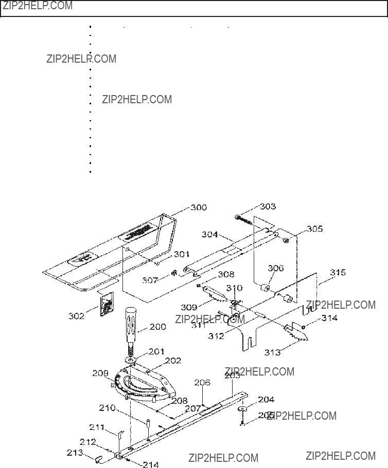
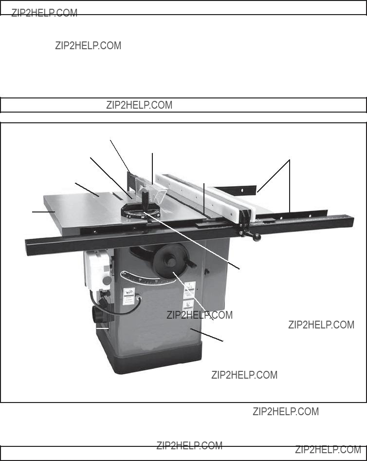
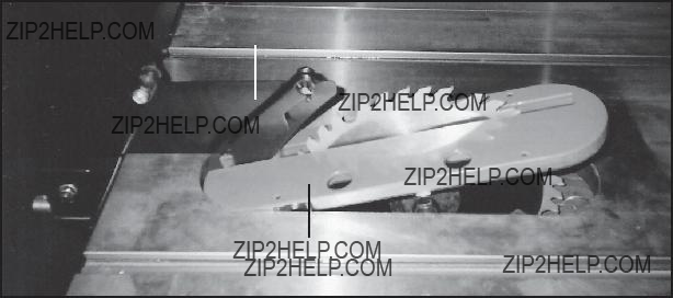
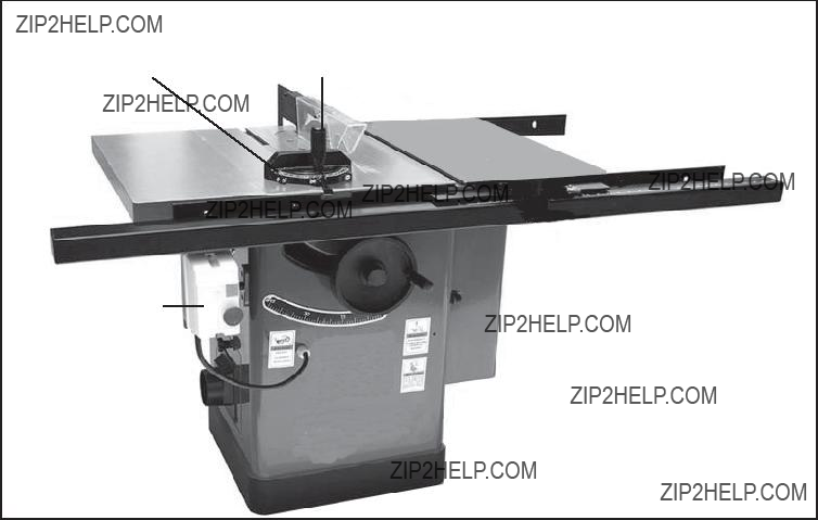
4.Set the Miter Gauge assembly (200 thru 214) on the Left Wing (113) of the Table Saw. (See FigureY.)

5.Operate the Miter Gauge assembly (200 thru 214) by loosening the Knob (200), and turning the Miter Gauge Body (202) to the desired angle of cut.

(See FigureY.)

6.Place the workpiece on the Table Saw and firmly against the Miter Gauge assembly (200 thru 214). (See FigureY.)

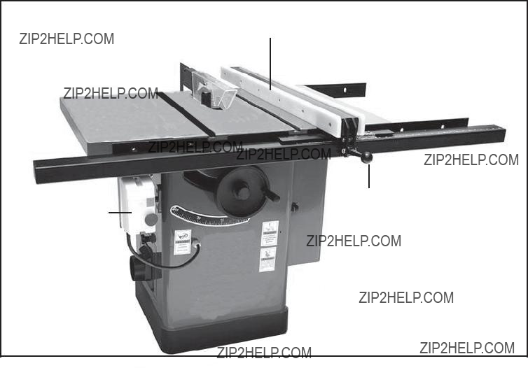
7.Plug the Power Cord Plug (130) into the nearest 220 volt, grounded, electrical outlet.

8.Depress the green ???ON??? Button on the Power Switch (137) to turn on the Table Saw. (See FigureY.)

9.When the Saw Blade is turning at full speed, slowly push the workpiece into the Saw Blade with the aid of the Miter Gauge assembly (200 thru 214). Do not force the Saw Blade to remove material faster than it is designed to cut.

10.Never attempt to remove material stuck in the moving parts of the Table Saw while it is plugged in and running.

11.Turn off the Table Saw if the workpiece is to be backed out of an uncompleted cut.

12.When the cut is complete, depress the red ???OFF??? Button on the Power Switch (137) to turn off the Table Saw. (See FigureY.)

13.Wait until the Saw Blade comes to a complete stop. Then, unplug the Power

Cord Plug (130) from its electrical outlet.

14.Remove the cut workpiece and debris from the Table Saw.

INSPECTION, MAINTENANCE, AND CLEANING

1. WARNING! Make sure the Power Switch (137) of the Table Saw is in its ???OFF??? position and the tool is unplugged from its electrical outlet before performing any inspection, maintenance, or cleaning procedures.

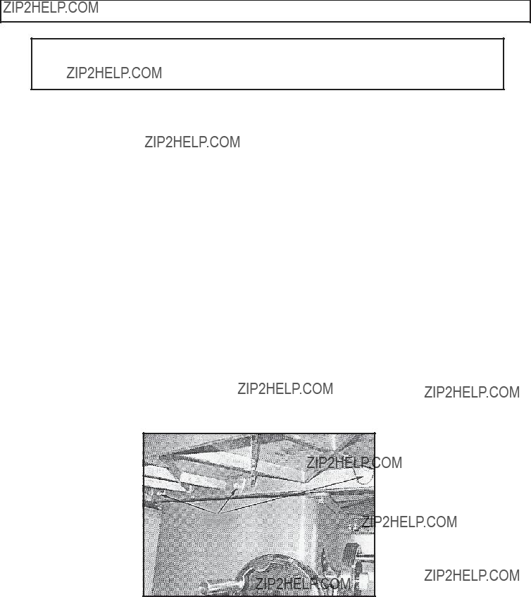
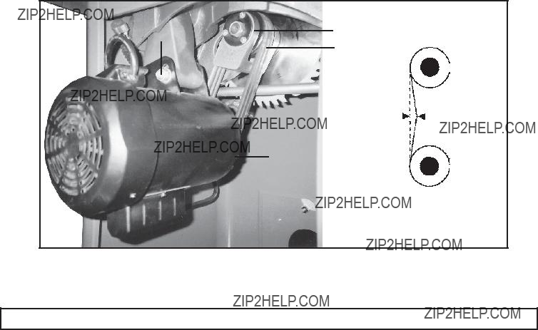
2.Before each use, inspect the general condition of the Table Saw. Check for proper guard alignment, damaged V-Belts, binding of moving parts, cracked or broken parts, damaged electrical wiring, and any other condition that may affect its safe operation. If abnormal noise or vibration occurs, have the problem corrected before further use. Do not use damaged equipment.

3.Before each use, inspect the Saw Blade. Using a dull Saw Blade will cause excessive wear on the Motor of the Table Saw and will not produce a satisfactory cut. Replace with a new Saw Blade when needed.

4.Before each use, open the Clean Out Door (12) and check for cleanliness. If necessary, use a vacuum to remove excessive saw dust from the interior of the Cabinet (1).

5.Every 12 months, lubricate the Geared Trunnion (52) and Front Trunnion (55). The Trunnions each have a semicircle groove that needs to be lubricated with an automotive wheel bearing grease.

6.Every 12 months, lubricate the Geared Bracket (102). The blade height Bracket pivots on a steel rod. This should be lubricated with 6 or 7 drops of light machine oil.

7.Every 12 months, lubricate the Worm Gears (18, 65). These should be lubricated with an automotive wheel bearing grease.

8.To change the V-Belts, lower the Saw Blade to its lowest point. Loosen the Bolt (35) on the Motor Bracket. Lift up on the Motor (34) to make the V-Belts (40) loose. Remove the V-Belts from the Spindle Pulley (99) and Motor Pulley (38). Replace and tension the V-Belts (the weight of the Motor should apply enough tension to the V-Belts). Then, retighten the Bolt on the Motor Bracket.

(See Figure Z, next page.)

Check the V-Belt tension after the Table Saw has been used for a few hours. Check and adjust as follows:

A.With moderate pressure, push the center of each V-Belt. Note the amount of deflection. Deflection should be approximately 1/2???. (See Figure Z.)

B.If the deflection is not 1/2???, loosen the Bolt (35) on the Motor Bracket. Shift the

Motor up or down to increase or decrease the V-Belt tension. Then, retighten the Bolt on the Motor Bracket. (See Figure Z.)

C.Check the V-Belt tension again. Also, make sure the Spindle Pulley (99) and

Motor Pulley (38) are lined up. (See Figure Z.)

9.To clean the exterior parts of the Table Saw, use only a clean cloth and mild detergent to clean the body of the Saw. Then, dry. Do not immerse any electrical part of the tool in any liquids.

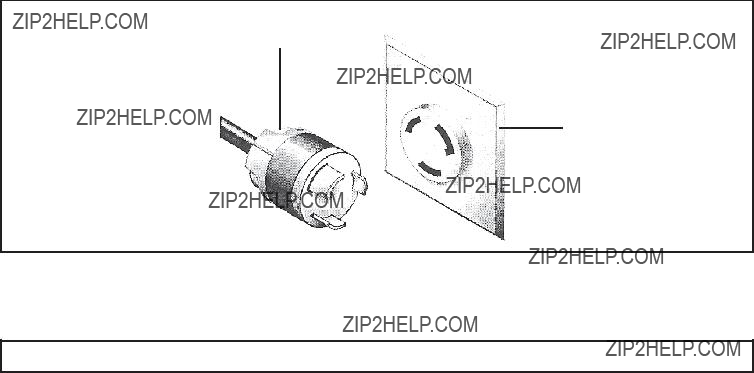
10.CAUTION! All maintenance, service, or repairs not mentioned in this manual must only be performed by a qualified service technician.

BOLT (35)

MOTOR PULLEY (38)

V-BELT (40)

1/2???

MOTOR (34)

FIGURE Z

PLEASE READ THE FOLLOWING CAREFULLY

THE MANUFACTURER AND/OR DISTRIBUTOR HAS PROVIDED THE PARTS LIST AND ASSEMBLY

DIAGRAM IN THIS MANUAL AS A REFERENCE TOOL ONLY. NEITHER THE MANUFACTURER OR

DISTRIBUTOR MAKES ANY REPRESENTATION OR WARRANTY OF ANY KIND TO THE BUYER THAT

HE OR SHE IS QUALIFIEDTO REPLACE ANY PARTS OF THE PRODUCT. IN FACT, THE MANUFACTURER

AND/OR DISTRIBUTOR EXPRESSLY STATES THAT ALL REPAIRS AND PARTS REPLACEMENTS

SHOULD BE UNDERTAKEN BY CERTIFIED AND LICENSED TECHNICIANS, AND NOT BY THE BUYER.

THE BUYER ASSUMES ALL RISKS AND LIABILITY ARISING OUT OF HIS OR HER REPAIRS TO THE

ORIGINAL PRODUCT OR REPLACEMENT PARTS THERETO, OR ARISING OUT OF HIS OR HER

INSTALLATION OF REPLACEMENT PARTS THERETO.

TROUBLESHOOTING

PARTS LIST

ASSEMBLY DIAGRAM

NOTE:

Some parts are listed and shown for illustration purposes only, and are not available individually as replacement parts.

PARTS LIST AND ASSEMBLY DIAGRAM (CONT.)

NOTE:

Some parts are listed and shown for illustration purposes only, and are not available individually as replacement parts.

PARTS LIST AND ASSEMBLY DIAGRAM (CONT.)

5B

11B

6B

7B 8B 9B10B

18B

27B24B19B

26B

25B

23B

22B

21B

20B

NOTE:

Some parts are listed and shown for illustration purposes only, and are not available individually as replacement parts.

POWER SWITCH SCHEMATIC