COMPOUND SLIDE MITER
SAW - 12 INCH
 42818
42818
ASSEMBLY AND OPERATING INSTRUCTIONS
3491 Mission Oaks Blvd., Camarillo, CA 93011
Visit our Web site at http://www.harborfreight.com
Copyright ?? 2002 by Harbor Freight Tools??. All rights reserved. No portion of this manual or any artwork contained herein may be reproduced in any shape or form without the express written consent of Harbor Freight Tools.
For technical questions and replacement parts, please call 1-800-444-3353
Save This Manual
You will need the manual for the safety warnings and precautions, assembly instructions, operating and maintenance procedures, parts list and diagram. Keep your invoice with this manual. Write the invoice number on the inside of the front cover. Keep the manual and invoice in a safe and dry place for future reference.
Safety Warnings and Precautions
WARNING: When using tool, basic safety precautions should always be followed to re- duce the risk of personal injury and damage to equipment.
Read all instructions before using this tool!
1.Keep work area clean. Cluttered areas invite injuries.
2.Observe work area conditions. Do not use machines or power tools in damp or wet locations. Don???t expose to rain. Keep work area well lighted. Do not use electrically powered tools in the presence of flammable gases or liquids.
3.Keep children away. Children must never be allowed in the work area. Do not let them handle machines, tools, or extension cords.
4.Store idle equipment. When not in use, tools must be stored in a dry location to inhibit rust. Always lock up tools and keep out of reach of children.
5.Do not force tool. It will do the job better and more safely at the rate for which it was intended. Do not use inappropriate attachments in an attempt to exceed the tool capacity.
6.Use the right tool for the job. Do not attempt to force a small tool or attachment to do the work of a larger industrial tool. There are certain applications for which this tool was designed. Do not modify this tool and do not use this tool for a purpose for which it was not intended.
7.Dress properly. Do not wear loose clothing or jewelry as they can be caught in moving parts. Protective, electrically non-conductive clothes and non-skid footwear are recommended when working. Wear restrictive hair covering to contain long hair.
8.Use eye and ear protection. Always wear ANSI approved impact safety goggles. Wear a full face shield if you are producing metal filings or wood chips. Wear an ANSI approved dust mask or respirator when working around metal, wood, and chemical dusts and mists.
9.Do not overreach. Keep proper footing and balance at all times. Do not reach over or across running machines.
10.Maintain tools with care. Keep tools sharp and clean for better and safer performance. Follow instructions for lubricating and changing accessories. Inspect tool cords periodically and, if damaged, have them repaired by an authorized technician.
The handles must be kept clean, dry, and free from oil and grease at all times.
11.Disconnect power. Unplug tool when not in use.
12.Remove adjusting keys and wrenches. Check that keys and adjusting wrenches are removed from the tool or machine work surface before plugging it in.
13.Avoid unintentional starting. Be sure the switch is in the Off position when not in use and before plugging in. Do not carry any tool with your finger on the trigger, whether it is plugged in or not.
14.Stay alert. Watch what you are doing, use common sense. Do not operate any tool when you are tired.
15.Take caution as some woods contain preservatives such as copper chromium arsenate (CCA) which can be toxic. When cutting these materials extra care should be taken to avoid inhalation and minimize skin contact.
16.Guard against electric shock. Prevent body contact with grounded surfaces such as pipes, radiators, ranges, and refrigerator enclosures.
17.Maintenance. For your safety, service and maintenance should be performed regularly by a qualified technician.
18.Check for damaged parts. Before using any tool, any part that appears damaged
should be carefully checked to determine that it will operate properly and perform its intended function. Check for alignment and binding of moving parts; any broken parts or mounting fixtures; and any other condition that may affect proper operation. Any part that is damaged should be properly repaired or replaced by a qualified technician. Do not use the tool if any switch does not turn On and Off properly.
19.Replacement parts and accessories. When servicing, use only identical replacement parts. Use of any other parts will void the warranty. Only use accessories intended for use with this tool. Approved accessories are available from Harbor Freight Tools.
20.Do not operate tool if under the influence of alcohol or drugs. Read warning labels on prescriptions to determine if your judgment or reflexes are impaired while taking drugs. If there is any doubt, do not operate the tool.
21.Use proper size and type extension cord. If an extension cord is required, it must be of the proper size and type to supply the correct current to the tool without heating up.
Otherwise, the extension cord could melt and catch fire, or cause electrical damage to the tool. This tool requires use of an extension cord of 0 to 15 amps capability (up to 50 feet), with wire size rated at 14 AWG. Longer extension cords require larger size wire. If you are using the tool outdoors, use an extension cord rated for outdoor use. (Signified by ???WA??? on the jacket).
22.Pacemaker safety warning. People with pacemakers should consult with their physician(s) before using this product; operation of equipment in close proximity to a heart pacemaker could cause interference or failure of the pacemaker.
Safety Precautions when using a Compound Slide Miter Saw
1.Do not disable blade guard. Do not saw without proper blade guard in place.
2.Examine blade before using. Before each use, examine blade for chips, cracks, or other damage. Do not use if damaged.
3.Do not use without first mounting saw to a workbench.
4.Check for tightness on all saw adjustments before using.
5.Keep hands away from moving saw blade. If the workpiece to be cut is less than 4 inches long, do not hold with your hand, use a clamp. Do not remove jammed or cutoff pieces until the saw blade has stopped and the Line Cord is unplugged.
6.Cut only the proper type of material. Never cut ferrous metals or masonry.
7.Avoid Blade to Base contact. The Blade should not contact the turn base in the lowest position.
8.Never use hands to secure workpiece. The workpiece must be secured firmly against the turn base and guide fence with a vise or clamp during all operations.
9.Avoid injuries. Never reach around saw blade.
10.Be alert when turn the Miter Saw on. The blade should not contact the workpiece before switching it on. Let the blade reach full speed before cutting.
11.Make adjustments safely. Unplug the power cord before making any adjustments to the Miter Saw, or to the workpiece.
Note: Performance of this tool may vary depending on variations in local line voltage. Exten- sion cord usage may also affect tool performance.
Warning:The warnings, cautions, and instructions discussed in this instruction manual cannot cover all possible conditions and situations that may occur. It must be under- stood by the operator that common sense and caution are factors which cannot be built into this product, but must be supplied by the operator.
Unpacking
When unpacking, check to make sure the following parts are included: Assembled Com- pound Slide Miter Saw, dust collection bag, set plate, set plate holder, arbor nut wrench, 4 mm hex wrench, and 5/8??? to 1??? arbor adapter. If any parts are missing or broken, please call Harbor Freight Tools at the number on the cover of this manual as soon as possible.
Installation
1.Place the Miter Saw on the solid workbench capable of supporting the weight of the unit and all work pieces. (Do not carry the unit by the Handle or misalignment of the components may occur.)
2.Using a pencil, mark through the saw Base (133) holes onto the workbench.
3.Drill two 3/8 inch holes into the workbench for the mounting hardware.
4.Secure the unit to the workbench using bolts, nuts, lock washers (not supplied).
5.Check and tighten all bolts and adjustment screws.
6.Insert the Dust Collection Bag.
Operation
WARNING: Some dust created by power sanding, sawing, grinding, drilling, and other construction activities, contain chemicals known [to the State of California] to cause cancer, birth defects or other reproductive harm. some examples of these chemicals are:
???Lead from lead-based paints
???Crystalline silica from bricks and cement or other masonry products
???Arsenic and chromium from chemically treated lumber
Your risk from these exposures varies, depending on how often you do this type of work. To reduce your exposure to these chemicals: work in a well ventilated area, and work with approved safety equipment, such as those dust masks that are specially de- signed to filter out microscopic particles. (California Health & Safety Code 25249.5, et seq. )

Auxiliary Wood Fence
To help avoid small, short cut pieces of stock from being caught by the blade or shot off, it is recommended to mount an auxiliary wood fence to the saw???s metal fence.
1.Cut a 1/2 inch thick piece of wood to match the height and length of the existing fence.
2.Mount the wood fence to the metal fence using flathead screws and nuts (two screws on each side of the fence).
The wood fence should rest on the table. Screws should be countersunk into the wood. (Hardware and wood not supplied.)
3.Start the saw and make a 90 degree cut all the way through the auxiliary wood fence.
The saw can now be safely used to cut small pieces of stock at 90 degrees to the table.
Positioning the Kerf Boards
The Kerf Boards (118 and 121), located in the Turn Base (117), are factory adjusted so that the saw blade does not contact them when the saw blade is lowered during a cut. See the illustration below. If the saw blade touches either Kerf Board, from any angle, adjustment is necessary.
1.Unplug the Line Cord from the electrical outlet.
2.Loosen four Screws (119 and 120), front and back.
3.Loosen the Knob Screw (105) so that the saw blade carriage can move back and forth.
4.Lower the saw blade all the way down, in between the Kerf Boards, and pull the
Carriage forward.
5.Adjust the (front ends) Kerf Boards so that they almost touch the saw blade teeth.
Tighten the front Screws.
6.Push the Carriage all the way back (toward the guide Fence), and adjust the Kerf
Boards (rear) so that they almost touch the saw blade teeth. Tighten the rear Screws.
7.Loosen the Lever Rod (156) and turn the saw blade left and right for bevel cuts and recheck the Kerf Board front and rear settings. Readjust if necessary.
8.Securely tighten all Screws.
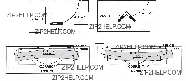
Preparation to Cut Stock
1.Before cutting stock, verify that it fits the base and fence properly and secure in place.
The photos below show the proper way to lay the stock on the base for cutting. These methods will keep the Saw Blade from binding with the stock, and keep it from rolling.
Use the Vertical Clamp to hold the stock in place for cutting.
2.Use the appropriate Saw Blade for the type of stock being cut. The Saw Blade provided is used for cutting wood.
Caution:The Safety Cover (88) returns to its original position when the cut is completed and the handle is raised. Never defeat or remove the Safety Cover.
3.Raise the cutting arm by pushing down slightly on the Handle (65), then pulling out the
Arm Release Button. See photo on the next page.
4.If making a vertical cut, verify that the Saw Blade is 90 degrees to the Table.
Adjust the Saw Blade angle by first loosening the Lever Rod (156) and turn the saw blade left or right so that the bevel scale pointer is set to zero. See photo on the next page.
5.If making miter cuts, raise the Handle (65) fully then loosen the handle Grip (128). Push the handle Grip to adjust the Saw Blade to the desired angle ranging from 0 to
45 degrees, left or right (positive stops at 0 and 45 degrees). When adjusted, tighten the handle Grip (128) again. Make sure that the Vertical Clamp is clear of the cutting path.
6.If making bevel (angle) cuts, raise the Handle (65) fully and loosen the Lever Rod (156) and push down on the Bevel Knob (146) to pass positive stops while moving the Handle (and Saw Blade) to the desired angle (left or right). Use the Bevel Scale as a guide. Tighten Lever Rod again.
Caution: Check that the Kerf Boards do not touch the Saw Blade. Adjust if necessary.
7. To slide the cutting arm backward, loosen the knob Screw (105), and slide the arm
back. Tighten the knob Screw again.
REV 05/04 REV 03/06

Cutting Stock
1.Plug the Power Cord into the electrical outlet.
2.With the workpiece secure, turn on the saw by pressing down on the Lock-off Switch Button (64), then squeeze the Switch (70) trigger button.
Lock-off Switch Button (64)

 Handle (65)
Brush Holder Cap (14)
Switch (70) Trigger Button
Dust Collection Bag
Slide Pipe (44)
Safety Cover (88)
Knob Screw (105)
Arm Release Button
Bevel Knob (146)
Fence
Lever Rod (156)
 Kerf Boards (121 & 118)
Bevel Scale
Handle Grip (128)
Vertical Clamp
Miter Scale
3.When the Saw Blade comes to full speed, bring the Saw Blade down and begin cutting slowly through the stock without stopping.
Warning: Avoid personal injury. Do not disable the Saw Blade Safety Cover (88). Keep fingers and hands away from the moving blade.
4.When the cut is finished, release the Switch (70) trigger button.
Wait for the Saw Blade to stop turning before reaching for the cut stock.
5.When you are finished using the saw, press the cutting head down until it locks into position.
6.Unplug the Power Cord from the electrical outlet.
7.Pull out the Lock-off Switch Button (64) and store in a secure place. This prevents unauthorized operation.
Slide Cutting
To cut larger pieces of stock, follow these steps.
1.Secure the workpiece to the table and fence.
2.Loosen the Knob Screw (105) so that the carriage can slide freely.
3.Raise the cutting arm by pushing down slightly on the Handle, then pulling out the Arm Release Button.

4.Pull the carriage all the way forward with the Handle (65).
5.Turn on the saw by pressing down on the Lock-off Switch Button (64), then squeeze the Switch (70) trigger button.
6.When the Saw Blade comes to full speed, bring the Saw Blade down and begin cutting slowly down through the stock until the Saw Blade is completely lowered. Then begin pushing the Handle back toward the fence.
Caution: Whenever performing a slide cut, the cut must be done from front to back. Otherwise, the workpiece may be forced out of the clamps and kick back. Kick back of the workpiece could cause injury.
7.When the cut is finished, release the Switch (70) trigger button.
Wait for the Saw Blade to stop turning before reaching for the cut stock.
Replacing the Saw Blade
1.Unplug the Power Cord Plug from the electrical outlet.
2.Loosen Hex Bolt (A). See illustrations below.
3.Push up on the right side of the Safety Cover (88) releasing it from around the Bolt.
4.Push the Shield assembly out of the way of the Blade Case (31).
5.Press in on the Shaft Lock Button. See illustration on the next page.
6.Place a socket wrench on the Hex Flange Bolt (83) and turn clockwise until the Bolt and Flange can be removed.
Spindle (77)
Inner Flange (80)

Shaft Lock Button
Hex Flange Bolt (83)
Socket Wrench
7.Remove the existing Saw Blade and replace with another 12 inch blade.
The new Saw Blade has an arrow on it that must be pointing in the same direction as the large arrow on the outside of the Blade Case (31).
Caution: Never use saw blades larger or smaller in diameter than 12 inches, and rated less than 5000 RPM operation.
8.Replace the Outer Flange (82) and Hex Flange Bolt (83).
9.Press in on the Spindle Lock button and retighten the Bolt in a counterclockwise direction with the socket wrench.
10.Replace the Safety Cover to its original position and retighten the Hex Bolt (A).
11.Press down on the saw Handle and verify that the safety Shield moves back properly, and that the blade does not touch the Fence or Table.
Maintenance
Replacing the Motor Brushes
It may become necessary at sometime to replace the motor brushes when the motor perfor- mance decreases, or stops working completely. The following steps describe their replace- ment. This procedure should be done by a qualified technician.
1.Unplug the Power Cord Plug from the electrical outlet.
2.Remove the Brush Holder Caps (14) and Carbon Brushes (13) from the Motor
Housing (16).
Examine the Carbon Brushes. If the they are worn past 3/16 inch in length, or if the spring or shunt wires are burnt, they must be replaced. Never replace just one brush. If the brushes are only dirty, and not worn down, you can use a pencil eraser to clean the brush tips.
3.Replace the Carbon Brushes (13) and Brush Holder Caps (14) .
4.Connect the Power Cord to an electrical outlet and test the saw???s operation.
General Maintenance
1.After use, blow table and motor holes clean with an air hose.
2.Empty Dust Collector Bag after each use.
Warning: Do not empty Dust Collection Bag around any sparks or flame. An explosion could occur.
3.Periodically wipe down all metal parts with a clean cloth and a light oil.
Never use solvents to clean plastic parts.
4.All motor bearings are factory lubricated and do not require maintenance.
Adjustments
Warning: Always disconnect power to the saw before making any adjustments. Adjust- ments should always be done by a qualified technician.
Saw Blade Perpendicular to Fence
1.Position the rotating table for a 90 degree cut.
2.Loosen the Knob Screw (105) and move the carriage completely back. Retighten the
Knob Screw.
3.Position the cutting arm to the 90 degree bevel stop (saw blade vertical).
4.Lower the Saw Blade and lock in place.
5.Place a tri-square against the Saw Blade and the Fence. If it is not exactly square, continue with the adjustment steps.
6.Loosen the Hex Bolts (92) directly behind the fence.
7.Adjust the fence until it is square with the Saw Blade.
8.Check the alignment from the other side of the Saw Blade. Readjust if necessary.
9.Securely retighten Hex Blots (92).
10.Check that the Pointer (122) on the Miter Scale points to zero degrees. If is does not, loosen its screw and adjust it to point to zero.
Downward Travel of the Saw Blade
1.Lower the Saw Blade as far as possible.
2.Turn the Blade by hand and verify the Blade teeth are not touching any metal surfaces.
3.Loosen the Hex Lock Nut (53) counterclockwise to lower the Saw Blade slightly.
4.Retighten Hex Lock Nut.
5.Lower the Saw Blade as far as possible and turn the Saw Blade. It should not touch anything while turning.

Bevel Stop to 90 Degrees
1.Position saw bevel stop at 90 degrees and loosen bevel Level Rod (156).
2.Lower the cutting head and place a Tri-square on the surface of the Blade and the left side of the Table. If it is not square, continue with the next step.
3.Push the Bevel Knob and adjust Saw Blade angle until the Saw Blade touches the Left Kerf Plate and is at 90 degrees to Table. Retighten Level Rod.
PLEASE READ THE FOLLOWING CAREFULLY
THE MANUFACTURER AND/OR DISTRIBUTOR HAS PROVIDED THE PARTS DIAGRAM IN THIS
MANUAL AS A REFERENCE TOOL ONLY. NEITHER THE MANUFACTURER NOR DISTRIBUTOR
MAKES ANY REPRESENTATION OR WARRANTY OF ANY KIND TO THE BUYER THAT HE OR
SHE IS QUALIFIED TO MAKE ANY REPAIRS TO THE PRODUCT OR THAT HE OR SHE IS QUALI-
FIED TO REPLACE ANY PARTS OF THE PRODUCT. IN FACT, THE MANUFACTURER AND/OR
DISTRIBUTOR EXPRESSLY STATES THAT ALL REPAIRS AND PARTS REPLACEMENTS SHOULD
BE UNDERTAKEN BY CERTIFIED AND LICENSED TECHNICIANS AND NOT BY THE BUYER.
THE BUYER ASSUMES ALL RISK AND LIABILITY ARISING OUT OF HIS OR HER REPAIRS TO
THE ORIGINAL PRODUCT OR REPLACEMENT PARTS THERETO, OR ARISING OUT OF HIS OR
HER INSTALLATION OF REPLACEMENT PARTS THERETO.
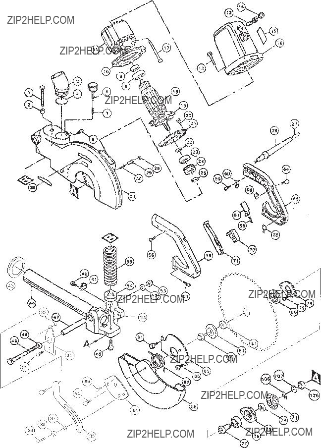
NOTE: Some parts are listed and shown for illustration purposes only and are not available indi- vidually as replacement parts.
Parts List
Note: The Vertical Clamp is not listed on this parts list nor shown in the diagrams on the following pages.