8.Industrial applications must follow OSHA requirements.
9.Remove adjusting keys and wrenches. Check to make sure all adjusting keys and wrenches are removed from this tool before turning it on.
10.Never attempt to remove material stuck in the moving parts of the Tile Saw while the tool is turned on, plugged in, or running.
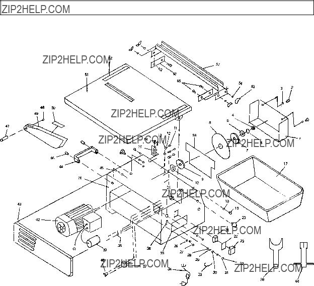
11.When replacing the Cutting Wheel Blade (8) make sure it is replaced with a 7??? diameter, minimum 8500 RPM rated, 1??? round arbor hole, wet diamond bonded Cutting Wheel Blade.
12.To avoid accidental injury, always wear heavy duty work gloves when chang- ing the Cutting Wheel Blade (8).
13.Make sure the Cutting Wheel Blade (8) is wet at all times when cutting.
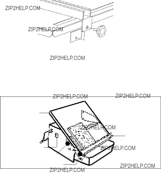
14.When operating theTile Saw, always make sure to fill theTray (17) with enough clean, cold water to cover the lower edge of the Cutting Wheel Blade (8), but not so deep as to spill over the edge of the Tray. Make sure the water supply for the Tile Saw is not dirty, sandy, and does not contain any corrosive chemical prod- ucts. Change the water when necessary while in use and rinse out the Tray (17) after every use.
15.Keep hands and fingers away from the cutting area and Cutting Wheel Blade
(8). Use a ???push stick??? (not included) if necessary.
16.Check Blade Guard (49) for proper up/down movement before each use.
Do not operate the Tile Saw if the Blade Guard does not move freely. Make sure the Blade Guard moves freely and does not touch the Cutting Saw Blade (8) or any other part of the Tile Saw, in all angles and depths of cut.
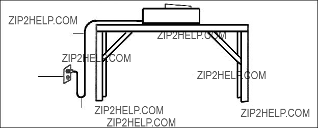
17.Make sure the Tile Saw is located on a flat, level, sturdy surface capable of supporting the weight of the Tile Saw, workpieces, and any additional tools.
18.Use the Tile Saw only for cutting ceramic tile, quarry tile, marble, terra cotta, and slate with a maximum thickness of 1 inch.
19.Do not use the Tile Saw for cutting metals or for cutting curves.
20.Before using the Tile Saw, make sure the Cutting Wheel Blade (8) is prop- erly mounted on the Saw Arbor. Make sure the Blade is balanced, and is not cracked or bent.
21.The Cutting Wheel Blade (8) will become hot while cutting. Allow the Blade to completely cool before handling.
22.Allow the Cutting Wheel Blade (8) to spin up to full speed before feeding a workpiece into it. When turning off the Tile Saw, allow the Cutting Wheel Blade to spin down and stop on its own. Do not press against the Blade to stop it.
 WARNING!
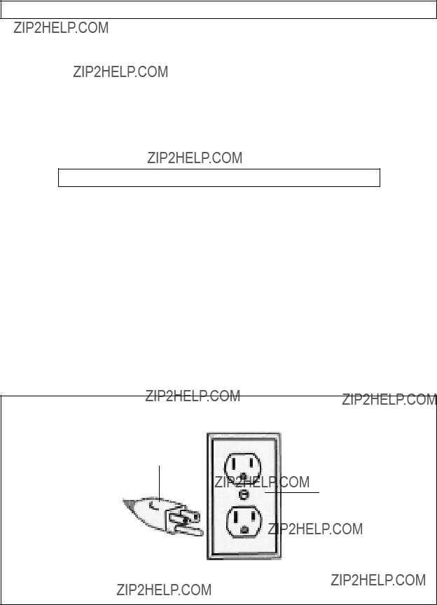
 eliminates the need for the three wire grounded power cord and grounded power supply system.


 WARNING!


 WARNING! Make sure the Power Switch (21) of the Tile Saw is in its ???OFF??? position and its Power Cord/Plug (34) is unplugged from the electri- cal outlet prior to performing any assembly.

 CUTTING WHEEL BLADE

 WARNING! Always turn the Tool Saw???s Power Switch (21) to its ???OFF??? po- sition and unplug the tool from its electrical outlet and before performing any inspection, maintenance, or cleaning.