3.Always turn off the Sander, remove the Switch Key (21), and unplug the unit from its electrical outlet before performing any inspection, maintenance, or cleaning procedures.
4.Never leave the Sander unattended when it is plugged into an electrical outlet.
Make sure to unplug the Sander from its electrical outlet and remove the Switch Key
(21) before leaving the area.
5.Store idle equipment. When not in use, tools and equipment should be stored in a dry location to inhibit rust. Always lock up tools and equipment, and keep out of reach of children.
6.Industrial applications must follow OSHA requirements.
7.Reduce the risk of accidental starting. Make sure the Power Switch is in its ???OFF??? position before plugging the Power Cord into a 120 volt, grounded, electrical outlet.
8.Before sanding, turn on the Sander and check for excessively loose Sanding Belt or Disc. If necessary, turn off the Sander and correct the problem before using.
9.Always keep hands and fingers as far away as possible from the moving parts of the Sander.
10.Use the right tools for the job. Do not attempt to force a small tool or attachment to do the work of a larger industrial tool or attachment. There are certain applications for which this tool was designed. It will do the job better and more safely at the rate for which it was intended. Do not modify this tool, and do not use this tool for a purpose for which it was not intended.
11.Allow the Sanding Belt and Sanding Disc to spin up to full speed before feeding a workpiece into them. When turning off the Sander, allow the Sanding Belt and Sanding Disc to slow down and stop on their own. Do not press against the Belt or Disc to stop them.
12.Feed the workpiece into the Sanding Belt and Sanding Disc gradually and into the direction of rotation. Do not attempt to force the Sander to remove material faster than it was designed to cut.
13.When replacing the Sanding Belt, make sure the Belt has a minimum 2000 FPM rating. When replacing the Sanding Disc, make sure the Disc has a minimum 3500 RPM rating.
14.To avoid damage to the Sander and personal injury, allow 1/16??? clearance between the Sanding Belt and Backstop and 1/16??? clearance between the Sanding Disc and Worktable.
15.When sanding a large workpiece, make sure its entire length is properly supported.
16.Never attempt to remove material stuck in the moving parts of the Sander while it is plugged in or running.
17.

 WARNING!
 Some dust created by power sanding, sawing, grinding, drilling, and other construction activities, contain chemicals known (to the State of California) to cause cancer, birth defects or other reproductive harm. Some examples of these
 38123
38123
 WARNING!
 eliminates the need for the three wire grounded power cord and grounded power supply system.


 People with pacemakers should consult their physician(s) before using this product. Operation of electrical equipment in close proximity to a heart pacemaker could cause interference to or failure of the pacemaker.


 The warnings, precautions, and instructions discussed in this manual cannot cover all possible conditions and situations that may occur. The operator must understand that common sense and caution are factors which cannot be built into this product, but must be supplied by the operator.
 WARNING!
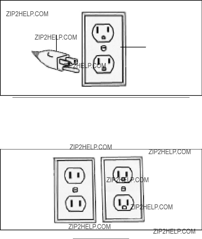


 WARNING!
 Make sure the Power Switch of the Sander is in its ???OFF??? position, the Switch Key (21) is removed, and its Power Cord/Plug is un- plugged from the electrical outlet prior to performing any assembly.
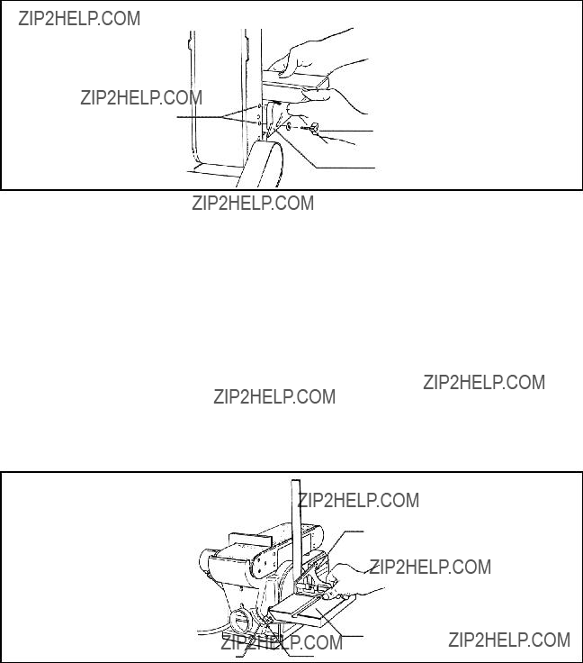


 Always turn the Sander???s ON/OFF Locking Switch (22) to its ???OFF??? position, remove the Switch Key (21), and unplug the machine from its electrical outlet and before performing any inspection, maintenance, or cleaning.


 All maintenance, service, or repairs not listed in this manual are only to be attempted by a qualified service technician.