COIL ROOFING NAILER

Model 68024

SET UP AND OPERATING INSTRUCTIONS

Visit our website at: http://www.harborfreight.com

Read and understand tool labels and manual. Failure to follow warnings could result in DEATH or SERIOUS INJURY.

SAVE THIS MANUAL.

Copyright?? 2010 by Harbor Freight Tools??. All rights reserved. No portion of this manual or any artwork contained herein may be reproduced in any shape or form without the express written consent of Harbor Freight Tools. Diagrams within this manual may not be drawn proportionally. Due to continuing improvements, actual product may differ slightly from the product described herein. Tools required for assembly and service may not be included.

For technical questions or replacement parts, please call 1???800???444???3353.

SAVE THIS MANUAL

Keep this manual for the safety warnings and precautions, assembly, operating, inspection, maintenance and cleaning procedures. Write the product???s serial number in the back of the manual near the assembly diagram (or month and year of purchase if product has no number). Keep this manual and the receipt in a safe and dry place for future reference.

Safety Alert Symbol and Signal

Words

In this manual, on the labeling, and all other information provided with this product:

This is the safety alert symbol. It is used to alert you to potential personal injury hazards. Obey all safety messages that follow this symbol to avoid possible injury or death.

DANGER indicates a hazardous situation which, if not avoided, will result

in death or serious injury.

WARNING indicates a hazardous situation

which, if not avoided, could result in death or serious injury.

CAUTION, used with the safety alert

symbol, indicates a hazardous situation which, if not avoided, could result in minor or moderate injury.

NOTICE is used to address practices not

related to personal injury.

CAUTION, without the safety alert symbol, is

used to address practices not related to personal injury.

ImportantIMPORTANTSafety InstructionsSAFETY S

INSTRUCTIONS PERTAINING

TO A RISK OF FIRE, ELECTRIC

SHOCK, OR INJURY

TO PERSONS

WARNING ??? When using tools, basic precautions should always be followed, including the following:

General

a.To reduce the risks of electric shock, fire, and injury to persons, read all the instructions before using the tool.

Work area

a.Keep the work area clean and well lighted. Cluttered benches and dark areas increase the risks of electric shock, fire, and injury to persons.

b.Do not operate the tool in explosive atmospheres, such as in the presence of flammable liquids, gases, or dust.

The tool is able to create sparks resulting in the ignition of the dust or fumes.

c.Keep bystanders, children, and visitors away while operating the tool.

Distractions are able to result in the loss of control of the tool.

Personal safety

a.Stay alert. Watch what you are doing and use common sense when operating the tool. Do not use the tool while tired or under the influence of drugs, alcohol, or medication. A moment of inattention while operating the tool increases the risk of injury

to persons.

b.Dress properly. Do not wear loose clothing or jewelry. Contain long hair. Keep hair, clothing, and gloves away from moving parts. Loose clothes, jewelry, or long hair increases the risk of injury to persons as a result of being caught in moving parts.

c.Avoid unintentional starting. Be sure the trigger is released before connecting to the air supply. Do not carry the tool with your finger on the trigger or connect the tool to the air supply with the trigger pressed.

d.Do not overreach. Keep proper footing and balance at all times.

Proper footing and balance enables better control of the tool in unexpected situations.

e.Use safety equipment. A dust mask, non-skid safety shoes and a hard hat must be used for the applicable

conditions. Wear heavy-duty work gloves during use.

f.Always wear eye protection.

Wear ANSI-approved safety goggles with side shields.

g.Always wear hearing protection when using the tool. Prolonged exposure to high intensity noise is able to

cause hearing loss.

h.Do not attach hose or tool to your body. Attach hose to structure to reduce risk of loss of balance if hose shifts.

i.Always assume that the tool contains fasteners. Do not point the tool toward yourself or anyone whether it contains fasteners or not.

j.WARNING ??? Do not fire fastener on top of another fastener. This is able to cause the fastener to be deflected and hit someone, or cause the tool to react and result in a risk of injury to persons.

k.WARNING ??? Remove finger from the trigger when not driving fasteners.

Never carry the tool with finger on trigger, the tool is able to fire a fastener.

Tool use and care

a.Use clamps or another practical way to secure and support the workpiece to a stable platform. Holding the work by hand or against the body is unstable and can lead to loss of control.

b.Do not force the tool. Use the correct tool for the application. The correct tool will do the job better and safer at the rate for which the tool is designed.

c.Do not use tool if trigger does not turn tool on or off. Any tool that cannot be controlled with the trigger is dangerous and must not be used until repaired.

d.Disconnect tool from air source before making adjustments, doing tool maintenance, clearing jams, touching safety nosepiece, leaving work area, loading, or unloading the tool. Such precautionary measures reduce the risk of injury to persons.

e.Store the tool when it is idle out of reach of children and other untrained persons. A tool is dangerous in the hands of untrained users.

f.Maintain the tool with care. A properly maintained tool reduces the risk of binding and is easier to control.

g.Check for misalignment or binding of moving parts, breakage of parts, and any other condition that affects the tool???s operation. If damaged, have the tool serviced before using. Many accidents are caused by poorly maintained tools. There is a risk of bursting if the tool is damaged.

h.Use only accessories that are identified by the manufacturer for the specific tool model. Use of an accessory not intended for use with the

specific tool model, increases the risk of injury to persons.

i.Use only those fasteners listed in the

Specifications chart of this manual.

Fasteners not identified for use with this tool by the tool manufacturer are able to result in a risk of injury to persons or tool damage when used in this tool.

Service

a.Tool service must be performed only by qualified repair personnel.

b.When servicing a tool, use only identical replacement parts. Use only authorized parts.

c.Use only the lubricants supplied with the tool or specified by

the manufacturer.

Air source

a.Never connect to an air source that is capable of exceeding 200 PSI. Over pressurizing the tool may

cause bursting, abnormal operation, breakage of the tool or serious injury to persons. Use only clean, dry, regulated compressed air at the rated pressure or within the rated pressure range as marked on the tool. Always verify prior to using the tool that the air source has been adjusted to the rated air pressure or within the rated air-pressure range.

b.Never use oxygen, carbon dioxide, combustible gases or any bottled gas as an air source for the tool. Such gases are capable of explosion and serious injury to persons.

SAVE THESE

INSTRUCTIONS.

Specific Safety Instructions

SPECIFIC INSTRUCTIONS

1.Operators and others in work area MUST wear ANSI-approved safety goggles with side shields during use.

The employer is responsible to enforce the use of eye protection by the operator and others in the work area.

2.Keep fingers away from trigger when not driving fasteners to avoid accidental firing.

3.Choice of triggering method is important. Check manual for triggering options.

4.Always assume tool contains fasteners.

5.Do not point tool toward yourself or anyone whether it contains fasteners or not.

6.Do not actuate the tool unless the tool is placed firmly against the workpiece.

7.Respect the tool as a working implement.

8.No horseplay. This tool is not a toy and can be deadly if misused.

9.Do not load tool with fasteners when any one of the operating controls, such as

Trigger or Safety Nosepiece, is activated.

10.Do not remove, tamper with, or otherwise cause the tool operating controls to become inoperable.

11.Do not operate if any portion of operating controls is inoperable, disconnected, altered, or not working properly.

12.Disconnect the tool from the air supply when:

a.Unattended.

b.Performing any maintenance or repair.

c.Clearing a jam.

d.Moving the tool to a new location.

13.Do not make any modifications to tool.

14.Refer to the tool maintenance instructions for detailed information on the proper maintenance of the tool.

15.Fire fasteners into an appropriate work surface only. Do not attempt to fire fasteners into surfaces too hard to penetrate. Do not drive fasteners on top of other fasteners, or at too steep of an angle. Fasteners can ricochet causing personal injury.

16.Do not fire fasteners too close to edge of a workpiece. They may split workpiece and fly free, causing personal injury.

17.Keep clear of workpiece near the area being fastened. Fasteners may bend sideways during firing, causing them to exit the workpiece at an unexpected point, causing personal injury.

18.Transport tool safely. Always disconnect air supply when moving tool. Carry tool by handle and avoid contact with trigger.

19.Hold tool away from head and body. During operation the tool may kick back causing injury.

20.Do not fire fasteners into a workpiece that has people, utility lines, or other objects behind or inside it.

21.Keep balance while using this tool.

Keep area below clear if working in an elevated location, and secure air hose to prevent falls from bystanders accidentally pulling on it.

22.Obey the manual for the air compressor used to power this tool.

23.Install in-line shutoff valve to allow immediate control over air supply in an emergency, even if a hose is ruptured.

24.Do not engrave or stamp anything into the housing to avoid weakening it.

25.WARNING: Some dust created by power sanding, sawing, grinding, drilling, and other construction activities, contains chemicals known [to the State of California] to cause cancer, birth defects or other reproductive harm.

Some examples of these chemicals are:

???Lead from lead-based paints

???Crystalline silica from bricks and cement or other masonry products

???Arsenic and chromium from chemically treated lumber

Your risk from these exposures varies, depending on how often you do this type of work. To reduce your exposure to these chemicals: work in a well ventilated area, and work with approved safety equipment, such as those dust masks that are specially designed to filter out microscopic particles. (California Health

& Safety Code ?? 25249.5, et seq.)

WARNING: The brass components of this product contain lead, a chemical known to the State of California to cause birth defects (or other reproductive harm). (California Health & Safety code

?? 25249.5, et seq.)

26.The warnings and precautions discussed in this manual cannot cover all possible conditions and situations that may occur. It must be understood by the operator that common sense and caution are factors which cannot be built into this product, but must be supplied by the operator.

Vibration Precautions

1.Anyone using vibrating tools regularly or for an extended period should first be examined by a doctor and then have regular medical check-ups to ensure medical problems are not being caused or worsened from use. Pregnant women or people who have impaired blood circulation to the hand, past hand injuries, nervous system disorders, diabetes, or Raynaud???s Disease should not use this tool. If you feel any symptoms related to vibration (such as tingling, numbness, and white or blue fingers), seek medical advice as soon as possible.

2.Do not smoke during use. Nicotine reduces the blood supply to the hands and fingers, increasing the risk of vibration-related injury.

3.Wear suitable gloves to reduce the vibration effects on the user.

4.Use tools with the lowest vibration when there is a choice between different processes.

5.Include vibration-free periods each day of work.

6.Grip tool as lightly as possible (while still keeping safe control of it). Let the tool do the work.

7.To reduce vibration, maintain tool as explained in this manual. If abnormal vibration occurs, stop immediately.

SAVE THESE

INSTRUCTIONS.

This tool vibrates during use. Repeated or long-term exposure to vibration may cause temporary or permanent physical injury, particularly to the hands, arms and shoulders. To reduce the risk of vibration-related injury:

FUNCTIONAL DESCRIPTION

Functional Description

Specifications

Depth Knob

(52)

Safety Nosepiece - Also called the workpiece contact, the Safety Nosepiece helps prevent the tool from firing unless it is pressed against an object.

Depth Knob - This controls the nail depth. Push the Knob to the left for shorter nails

(or to fire nails less deep). Push the

Knob to the right for longer nails (or for deeper depths).

Roofing Gauge - This can be adjusted to guide the shingle spacing. Loosen the Cap Screw, adjust Gauge as needed, then retighten the Cap Screw.

INITIALASSEMBLY

Initial Tool Setup/Assembly

Read the ENTIRE IMPORTANT

SAFETY INFORMATION section at the beginning of this manual including all text under

subheadings therein before set up or use of this product.

Note: For additional information regarding the parts listed in the following pages, refer to the Assembly Diagram near the end of this manual.

Unpacking

When unpacking, make sure that the item is intact and undamaged. If any parts are missing or broken, please call Harbor

Freight Tools at 1???800???444???3353 as soon as possible.

???This air tool may be shipped with a protective plug covering the air inlet.

Remove this plug before set up.

Air Supply

TO PREVENT

EXPLOSION:

Use only clean, dry, regulated, compressed air to power this tool. Do not use oxygen, carbon dioxide, combustible gases, or any other bottled gas as a power source for this tool.

1.Connect a regulator valve, an in-line shut off valve, and 1/4??? NPT air hose (all sold separately) to the Quick Coupler. Use thread tape for all threaded connections. The air hose must be long enough to reach the work area with enough extra length to allow free movement while working. An in-line shutoff ball valve is an important safety device because it controls the air supply even if the

.3353-444-800-1 call please questions, technical For 68024 SKU

9 Page

Tool Air

F &Spray

Stationary Gun

Setup

air hose is ruptured. The shutoff valve should be a ball valve because it can be closed quickly. See pages 8 and 9 for Air Tool Setup procedures.

Note: If an automatic oiler system is not used, add a few drops of Pneumatic Tool Oil into the airline connection before operation. Add a few more drops after each hour of continual use.

2.Attach an air hose to the compressor???s air outlet. Connect the air hose to the air inlet of the tool. Please note: a quick coupler will be needed for proper connection.

WARNING! TO PREVENT SERIOUS

INJURY FROM ACCIDENTAL OPERATION: Do not install a quick coupler on the tool. A coupler contains an air valve that will allow the air tool to retain pressure and operate accidentally after the air supply is disconnected.

Note: Air flow, and therefore tool performance, can be hindered by undersized air supply components.

3.The air hose must be long enough to reach the work area with enough extra length to allow free movement while working.

4.Release the tool???s Trigger (44).

5.Close the in-line safety valve between the compressor and the tool.

6.Turn on the air compressor according to the manufacturer???s directions and allow it to build up pressure until it cycles off.

7.Adjust the air compressor???s output regulator so that the air output is enough to properly power the tool, but the output will not exceed the tool???s maximum

air pressure at any time. Adjust the pressure gradually, while checking

the air output gauge to set the right pressure range.

8.The air pressure setting must not exceed job site regulations/restrictions. The air pressure setting must not exceed 90 PSI when being used with work pieces that have a thickness of less than 1-3/4???.

9.Inspect the air connections for leaks.

Repair any leaks found.

10.If the tool will not be used at this time, turn off and detach the air supply, safely discharge any residual air pressure, and release the trigger to prevent accidental operation.

Note: Residual air pressure should not be present after the tool is disconnected from the air supply. However, it is a good safety measure to attempt to discharge the tool in a safe fashion after disconnecting to ensure that the tool is disconnected and unpowered.

Nail Penetration Depth Adjustment

1.With the tool connected to its air supply and with the nails loaded, test fire on a scrap material (similar to the workpiece) and note the depth of nail???s penetration.

2.To adjust nail depth penetration, rotate the Depth Knob (52). Turn the Depth Knob to the left (+) for deeper nail penetration and to the right (-) for more shallow penetration.

3.CAUTION! When working with asphalt shingles in particular, the nail head should not sink below the top face of the shingle.

OPERATING INSTRUCTIONS

Operating Instructions

Read the ENTIRE IMPORTANT

SAFETY INFORMATION section at the beginning of this manual including all text under

subheadings therein before set up or use of this product.

Inspect tool before use, looking for damaged, loose, and missing parts. If any problems are found, do not use tool until repaired.

Work Piece and Work Area Set Up

1.Designate a work area that is clean and well-lit. The work area must not allow access by children or pets to prevent distraction and injury.

2.Route the air hose along a safe path to reach the work area without creating a tripping hazard or exposing the air hose to possible damage. The air hose must be long enough to reach the work area with enough extra length to allow free movement while working.

3.Secure loose workpieces using a vise or clamps (not included) to prevent movement while working.

4.There must not be hazardous objects

(such as utility lines or foreign objects) nearby that will present a hazard while working.

Contact Safety Trip (Bump Fire)

Mechanism Definition

When selected, the Bump Fire mechanism allows for rapid firing. To set the

Nailer in Bump Fire mode, turn the Mode

Switch (41) to the Bump Fire Position (as indicated by the two bump fire symbols).

The tool should only fire if the Safety

Nosepiece is pressed against the workpiece and the trigger is pulled. It should fire again if the trigger is released and pulled OR

if the safety is lifted and pressed against the workpiece again. The Tool should not fire if the Safety Nosepiece is not pressed against an object. Contact safety trip / bump fire should only be enabled and used by skilled operators who are aware of the hazards and use proper, safe work practices.

Contact Safety Trip (Bump Fire)

Mechanism Testing Procedure

TO PREVENT

SERIOUS INJURY

FROM ACCIDENTAL

OPERATION:

Empty the tool before this procedure. Point the tool at a piece of scrap wood

when testing.

1.Disconnect the tool from the air supply.

2.Empty the magazine of fasteners.

3.Check that the Trigger and the Safety

Nosepiece move freely, without sticking.

4.Connect the air supply to the tool and set within the Operating Air Pressure indicated on the Specification chart.

5.Test the tool by pressing the Safety Nosepiece against the workpiece without pulling the Trigger. The tool must not cycle (fire). If it cycles (fires), stop immediately and take the tool to a qualified service technician for repair.

6.Hold the tool away, or off of the workpiece. The Safety Nosepiece should return to its original position.

Squeeze the Trigger. The tool must not cycle (fire). If it cycles (fires),

stop immediately and take the tool to a qualified service technician.

7.Press the Safety Nosepiece against the workpiece and squeeze the Trigger.

The tool must cycle (fire) only once.

Release the trigger and squeeze it again. The tool must cycle (fire) again only once. With the Trigger held, carefully lift the tool and press it against the workpiece again. The tool must cycle (fire) again only once. If it fails to act in the manner explained in bold, have it repaired by a qualified service technician.

Single Sequential Safety Trip

Mechanism Definition

The Single Sequential safety trip mechanism is designed to prevent inadvertent firing. To set the Nailer in the Single

Sequential mode, turn the Mode Switch to the

Single Sequential position (as indicated by the single bump fire symbol).

The tool should only fire if the Safety

Nosepiece is pressed against the workpiece prior to pulling the Trigger. It should only fire again if the trigger is released and squeezed again. The Tool should not fire if the Safety

Nosepiece is not pressed against an object.

Single Sequential Safety Trip

Mechanism Testing Procedure

TO PREVENT

SERIOUS INJURY

FROM ACCIDENTAL OPERATION: Empty the tool before this procedure. Point the tool at a piece of scrap wood when testing.

1.Disconnect the tool from the air supply.

2.Empty the magazine of fasteners.

3.Check that the Trigger and the Safety Nosepiece move freely, without sticking.

4.Connect the air supply to the tool and set within the Operating Air Pressure indicated on the Specification chart.

5.Test the tool by pressing the Safety Nosepiece against the workpiece without pulling the Trigger. The tool must not cycle (fire). If it cycles (fires), stop immediately and take the tool to a qualified service technician for repair.

6.Hold the tool away, or off of the workpiece. The Safety Nosepiece should return to its original position.

Squeeze the Trigger. The tool must not cycle (fire). If it cycles (fires), stop immediately and take the tool to a qualified service technician.

7.Press the Safety Nosepiece against the workpiece and squeeze the Trigger.

The tool must cycle (fire) only once.

Release the trigger and squeeze it again. The tool must cycle (fire) again only once. With the Trigger held, carefully lift the tool and press it against the workpiece again. The tool must not cycle (fire). If it fails to act in the manner explained in bold, have it repaired by a qualified service technician.

Loading the Tool

TO PREVENT

SERIOUS INJURY

FROM ACCIDENTAL OPERATION,

BEFORE LOADING:

???Wear ANSI-approved safety goggles with side shields. Other people in the work area must also wear ANSI-approved impact safety goggles with side shields.

???Release the trigger.

???Detach the air supply.

???Attempt to fire the Tool into a piece of scrap wood to ensure that it is disconnected and is incapable of firing any fasteners.

1.To open the Magazine Cover (85), pull up on the Latch (81) and pull back the

Moveable Cover Plate (80).

2.Once the Cover Plate is lifted, lift up the Magazine Cover.

3.Check the Nail Support (92) inside the Magazine. Twist the Support and pull it up (or down) to adjust to use various lengths of nails from 3/4??? to 1-3/4???:

A.3/4??? Long Nails

(Use top setting marked on inside of Magazine).

B.Between 3/4??? and 1-3/4??? Long Nails (Use middle setting marked on inside of Magazine).

C.1-3/4??? Long Nails

(Use bottom setting marked on inside of Magazine).

3.Place a coil of nails around the Nail

Support in the Magazine.

4.Uncoil enough nails to reach the Drive Guide (29). Place the second nail on the coil between the tabs of the Drive Guide, making sure the nail head fits in the slot in the top end of the Drive Guide.

5.Swing the Magazine Cover closed. Then, close the Cover Plate, making sure the Latch snaps shut. If the Latch does not engage, the nail head is not in the slot in the upper portion of the Feed

Drive Guide.

Roofing Gauge Adjustment

1.The Roofing Gauge (82) controls roof shingle spacing. To adjust the Roofing

Gauge to work with a particular width of shingles, use the accessory Hex Wrench to loosen the Hex Bolt (83) on the

Roofing Gauge.

2.Slide the Bracket forward or backward to the desired shingle spacing.

3.Then, retighten the Hex Bolt.

General Operating Instructions

1.Test the Tool, as directed on page 10 or 11, before each use.

2.If an automatic oiler is not used, add a few drops of Pneumatic Tool Oil to the airline connection before use. Add a few drops more after each hour of continual use.

3.Attach the air hose to the Nailer. Start your compressor and check the pressure making sure it is not set to go over the maximum 120 PSI.

4.To fire, place the nose of the Nailer on the workpiece. The Nailer should not fire if the nose is not depressed.

Once depressed, gently and briefly squeeze the Trigger once. Do not fire repeatedly. Nails could bounce off of one another, damaging the workpiece or causing PERSONAL INJURY.

5.If the tool requires more force to accomplish the task, verify that the tool receives sufficient, unobstructed airflow (CFM) and increase the pressure

(PSI) output of the regulator up to the maximum air pressure rating of this tool.

CAUTION! TO PREVENT TOOL AND

ACCESSORY FAILURE, RESULTING IN INJURY: Do not exceed the tool???s maximum air pressure rating.

If the tool still does not have sufficient force at maximum pressure and sufficient airflow, then a larger tool may be required.

Note: While working on roofs, tar and dirt may build up on the Nose of the

Roofing Nailer. This can prevent normal operation. Remove buildup with a nonflammable solvent. NEVER use gasoline or other flammable solvents. Do not immerse the Roofing Nailer in an approved solvent beyond the height of the nail heads, to avoid getting the solvent into the drive cylinder of the tool. Dry off the Roofing Nailer before use; any oil film left after cleanup will accelerate tar buildup.

6.After use, to prevent accidents:

a.Release the trigger.

b.Detach the air supply.

c.Attempt to fire the Tool into a piece of scrap wood to ensure that it is incapable of firing any fasteners.

d.Release the trigger again.

e.Clean external surfaces with clean, dry cloth.

f.Store indoors out of children???s reach.

USER-INSTRUCTIONS

User-Maintenance Instructions

Procedures not specifically explained in this manual must be performed only by a qualified technician.

TO PREVENT

SERIOUS INJURY

FROM ACCIDENTAL OPERATION,

BEFORE ANY MAINTENANCE OR REPAIRS ARE DONE (including clearing jams):

???Wear ANSI-approved safety goggles with side shields. Other people in the work area must also wear ANSI-approved impact safety goggles with side shields.

???Release the Trigger.

???Detach the air supply.

???Attempt to fire the Tool into a piece of scrap wood to ensure that it is disconnected and is incapable of firing any fasteners.

???Empty the magazine and leave it open during service. The Magazine is spring-loaded and may cause parts or a fastener to fly out of the Tool.

TO PREVENT SERIOUS INJURY

FROM TOOL FAILURE:

Do not use damaged equipment. If abnormal noise, vibration,

or leaking air is detected, have the problem corrected before further use.

TO PREVENT EXPLOSION:

Lubricate only with specified lubricants. Lubricate the air inlet using only pneumatic tool oil. Lubricate the internal mechanism using only white lithium grease. Other lubricants may damage the

mechanism and may be highly flammable, causing an explosion.

Note: These procedures are in addition to the regular checks and maintenance explained as part of the regular operation of the air-operated tool.

Daily - Air Supply Maintenance:

Every day, perform maintenance on the air supply according to the component manufacturers??? instructions. If equipped. the lubricator???s oil level needs to be maintained and the moisture filter must be regularly drained. Performing routine maintenance on the air supply will allow the tool to operate more efficiently and will also reduce wear on the tool.

Clearing Jams

TO PREVENT

SERIOUS INJURY

FROM ACCIDENTAL OPERATION,

BEFORE ANY MAINTENANCE OR REPAIRS ARE DONE (including clearing jams):

???Wear ANSI-approved safety goggles with side shields. Other people in the work area must also wear ANSI-approved impact safety goggles with side shields.

???Release the trigger.

???Detach the air supply.

???Attempt to fire the Tool into a piece of scrap wood to ensure that it is disconnected and is incapable of firing any fasteners.

???Empty the magazine and leave it open during service. The Magazine is spring-loaded and may cause parts or a fastener to fly out of the Tool.

1.If a fastener is jammed in the discharge area, pull up on the Latch and lift up the

Moveable Cover Plate.

2.Remove the jammed fasteners with pliers.

3.If a fastener is jammed in the Magazine, lift open the Latch, and then swing back the moveable Cover Plate and then the

Magazine Cover.

4.Uncoil the fasteners and, if necessary, use a screwdriver to release the jammed fastener.

5.Pull out the jammed fastener.

6.If you are unable to clear the fastener jam using the method prescribed above, the tool should be taken to a qualified service technician for proper servicing.

Record Product???s Serial Number Here:

Note: If product has no serial number, record month and year of purchase instead.

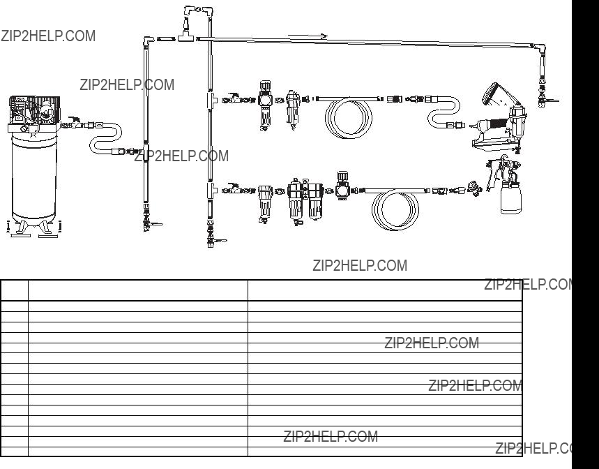
Note: Some parts are listed and shown for illustration purposes only, and are not available individually as replacement parts.

PLEASE READ THE FOLLOWING CAREFULLY

THE MANUFACTURER AND/OR DISTRIBUTOR HAS PROVIDED THE PARTS LIST AND ASSEMBLY

DIAGRAM IN THIS MANUAL AS A REFERENCE TOOL ONLY. NEITHER THE MANUFACTURER OR

DISTRIBUTOR MAKES ANY REPRESENTATION OR WARRANTY OF ANY KIND TO THE BUYER THAT HE

OR SHE IS QUALIFIED TO MAKE ANY REPAIRS TO THE PRODUCT, OR THAT HE OR SHE IS QUALIFIED

TO REPLACE ANY PARTS OF THE PRODUCT. IN FACT, THE MANUFACTURER AND/OR DISTRIBUTOR

EXPRESSLY STATES THAT ALL REPAIRS AND PARTS REPLACEMENTS SHOULD BE UNDERTAKEN BY

CERTIFIED AND LICENSED TECHNICIANS, AND NOT BY THE BUYER. THE BUYER ASSUMES ALL RISK

AND LIABILITY ARISING OUT OF HIS OR HER REPAIRS TO THE ORIGINAL PRODUCT OR REPLACEMENT

PARTS THERETO, OR ARISING OUT OF HIS OR HER INSTALLATION OF REPLACEMENT PARTS THERETO.

Troubleshooting

Follow all safety precautions whenever diagnosing or servicing the tool. Disconnect air supply before service.

Parts List

Diagram Assembly

Limited 1-Year Warranty

Harbor Freight Tools Co. makes every effort to assure that its products meet high quality and durability standards, and warrants to the original purchaser that this product is free from defects in materials and workmanship for the period of one year from the date of purchase

(90 days if used by a professional contractor or if used as rental equipment). This warranty does not apply to damage due directly or indirectly, to misuse, abuse, negligence or accidents, repairs or alterations outside our facilities, normal wear and tear, or to lack of maintenance.

We shall in no event be liable for death, injuries to persons or property, or for incidental, contingent, special or consequential damages arising from the use of our product. Some states do not allow the exclusion or limitation of incidental or consequential damages, so the above limitation of exclusion may not apply to you. THIS WARRANTY IS EXPRESSLY IN LIEU OF

ALL OTHER WARRANTIES, EXPRESS OR IMPLIED, INCLUDING THE WARRANTIES OF

MERCHANTABILITY AND FITNESS.

To take advantage of this warranty, the product or part must be returned to us with transportation charges prepaid. Proof of purchase date and an explanation of the complaint must accompany the merchandise. If our inspection verifies the defect, we will either repair or replace the product at our election or we may elect to refund the purchase price if we cannot readily and quickly provide you with a replacement. We will return repaired products at our expense, but if we determine there is no defect, or that the defect resulted from causes not within the scope of our warranty, then you must bear the cost of returning the product.

This warranty gives you specific legal rights and you may also have other rights which vary from state to state.

3491 Mission Oaks Blvd. ??? PO Box 6009 Camarillo, CA 93011 ??? (800) 444-3353

Page 20 For technical questions, please call 1-800-444-3353. SKU 68024