9??? X 20??? geared head, belt driven, bench lathe

Model 45861

Set up And Operating Instructions

Distributed exclusively by Harbor Freight Tools??.

3491 Mission Oaks Blvd., Camarillo, CA 93011

Visit our website at: http://www.harborfreight.com

Read this material before using this product. Failure to do so can result in serious injury. Save this manual.

Copyright?? 2008 by Harbor Freight Tools??. All rights reserved. No portion of this manual or any artwork contained herein may be reproduced in any shape or form without the express written consent of Harbor Freight Tools. Diagrams within this manual may not be drawn proportionally. Due to continuing improvements, actual product may differ slightly from the product described herein.

For technical questions or replacement parts, please call 1-800-444-3353.

Contents

Important SAFETY

Information ???????????????????????????????????????????????????????????????????????????????????? 3

General Power Tool

Safety Warnings ??????????????????????????????????????????????????????????????????3 Lathe Safety Warnings ????????????????????????????????????5

Grounding ??????????????????????????????????????????????????????????????????????????????????????????????????? 6

Grounded Tools: Tools

with Three Prong Plugs ?????????????????????6 Extension Cords ???????????????????????????????????????????????????????????????????????????7 Symbology???????????????????????????????????????????????????????????????????????????????????????????????????????????????7

Specifications?????????????????????????????????????????????????????????????????????????????? 9

Unpacking ?????????????????????????????????????????????????????????????????????????????????????????????????????? 9

List of contents??????????????????????????????????????????????????????????????????????????????9

Instructions for putting into use ???????????????????????????????????????????????????????????????????????????????????????????????????????????? 9

Mounting???????????????????????????????????????????????????????????????????????????????????????????????????????????????????????????9 Functions ???????????????????????????????????????????????????????????????????????????????????????????????????????????????10

Operating Instructions ???????????? 10

Tool Set Up ??????????????????????????????????????????????????????????????????????????????????????????????????????10

Workpiece and Work Area Set Up ??????????????????????????????????????????????????????????????????????????????????????????????????????????????????????????????10

Spindle Speeds?????????????????????????????????????????????????????????????????????????????????14

General Operating Instructions ????????????????????????????????????????????????????????????????????????????????????16

Maintenance And

Servicing ????????????????????????????????????????????????????????????????????????????????????????????? 19

Cleaning and Maintenance ?????????19 Lubrication??????????????????????????????????????????????????????????????????????????????????????????????????????19

Headstock Parts List ??????????????????????????? 21 Headstock diagram??????????????????????????????????????? 21 Drive Parts List??????????????????????????????????????????????????????????????? 22

Drive diagram ???????????????????????????????????????????????????????????????????????? 23

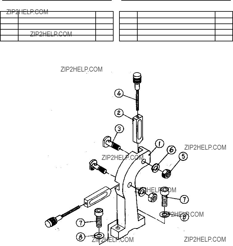
Tensioning roller Parts List ????????????????????????????????????????????????????????????????????????????????????????????????????????????????????????????????? 24

Quadrant Parts List ????????????????????????????????? 25 Motor housing Parts List??? 26 Bed Parts List ???????????????????????????????????????????????????????????????????????? 27 Gear box Parts List??????????????????????????????????????? 28 Gear box diagram ???????????????????????????????????????????????? 29 Apron Parts List????????????????????????????????????????????????????????? 30

Apron Parts List

continued?????????????????????????????????????????????????????????????????????????????????????????? 31

Saddle and cross slide Parts List ?????????????????????????????????????????????????????????????????????????????????????????? 32

Saddle and cross slide diagram ?????????????????????????????????????????????????????????????????????????????????????????????????????? 33

Tailstock Parts List???????????????????????????????????? 34 Tailstock diagram ????????????????????????????????????????????? 35

Travelling rest Parts

List ????????????????????????????????????????????????????????????????????????????????????????????????????????????????????????????????? 36 STEADY REST Parts List????????????????????? 37 Wiring diagram?????????????????????????????????????????????????????????????????? 38 Wiring diagram?????????????????????????????????????????????????????????????????? 39

Limited 1 year / 90 day Warranty ?????????????????????????????????????????????????????????????????????????????????????????? 40

Save This Manual

Keep this manual for the safety warn- ings and precautions, assembly, operat- ing, inspection, maintenance and cleaning procedures. Write the product???s serial number in the back of the manual near the assembly diagram (or month and year of purchase if product has no number). Keep this manual and the receipt in a safe and dry place for future reference.

Important SAFETY

Information

In this manual, on the labeling, and all other information provided with this product:

This is the safety alert symbol. It is used to alert you to potential personal injury hazards. Obey all safety messages that follow this symbol to avoid possible injury or death.

DANGER indicates a hazardous

situation which, if not avoided, will result in death or serious injury.

WARNING indicates a

hazardous situation which, if not avoided, could result in death or serious injury.

CAUTION, used with the safety

alert symbol, indicates a hazardous situation which, if not avoided, could result in minor or moderate injury.

NOTICE is used to address practices not related to personal injury.

CAUTION, without the safety alert

symbol, is used to address practices not related to personal injury.

General Power Tool Safety

Warnings

WARNING Read all safety warnings and instructions.

Failure to follow the warnings and instructions may result in electric shock, fire and/or serious injury.

Save all warnings and instructions for future reference.

The term ???power tool??? in the warnings refers to your mains- operated (corded) power tool.

1.Work area safety

a.Keep work area clean and well lit.

Cluttered or dark areas invite acci- dents.

b.Do not operate power tools in explosive atmospheres, such as in the presence of flammable liquids, gases or dust. Power tools create sparks which may ignite the dust or fumes.

c.Keep children and bystanders away while operating a power tool.

Distractions can cause you to lose control.

2.Electrical safety

a.Power tool plugs must match the outlet. Never modify the plug in any way. Do not use any adapter plugs with grounded power tools.

Unmodified plugs and matching out- lets will reduce risk of electric shock.

b.Avoid body contact with grounded surfaces such as pipes, radiators, ranges and refrigerators. There is an increased risk of electric shock if your body is grounded.

c.Do not expose power tools to rain or wet conditions. Water entering a power tool will increase the risk of electric shock.

d.Do not abuse the cord. Never use the cord to unplug the power tool. Keep cord away from heat, oil, sharp edges or moving parts.

Damaged or entangled cords in- crease the risk of electric shock.

e.If operating a power tool in a damp location is unavoidable, use a Ground Fault Circuit Interrupter (GFCI) protected supply. Use of

a GFCI reduces the risk of electric shock.

3.Personal safety

a.Stay alert, watch what you are do- ing and use common sense when operating a power tool. Do not use a power tool while you are tired

or under the influence of drugs, alcohol or medication. A moment of inattention while operating power tools may result in serious personal injury.

b.Use safety equipment. Always wear ANSI-approved eye protec- tion. Safety equipment such as dust mask, full face shield, heavy-duty work gloves, non-skid safety shoes, hard hat, or hearing protection used for appropriate conditions will reduce personal injuries.

c.Remove any adjusting key or wrench before turning the power tool on. A wrench or a key left at- tached to a rotating part of the power tool may result in personal injury.

d.Do not overreach. Keep proper footing and balance at all times.

This enables better control of the power tool in unexpected situations.

e.Dress properly. Do not wear loose clothing or jewelry. Keep your hair, clothing and gloves away from moving parts. Loose clothes, jewelry or long hair can be caught in moving parts.

f.If devices are provided for the con- nection of dust extraction and col- lection facilities, ensure these are connected and properly used. Use of these devices can reduce dust- related hazards.

4.Power tool use and care

a.Do not force the power tool. Use the correct power tool for your ap- plication. The correct power tool will do the job better and safer at the rate for which it was designed.

b.Do not use the power tool if the switch does not turn it on and off.

Any power tool that cannot be con- trolled with the switch is dangerous and must be repaired.

c.Disconnect the plug from the power source before making any adjustments, changing accesso- ries, or storing power tools. Such preventive safety measures reduce the risk of starting the power tool ac- cidentally.

d.Store idle power tools out of the reach of children and do not allow persons unfamiliar with the power

tool or these instructions to oper- ate the power tool. Power tools are dangerous in the hands of untrained users.

e.Maintain power tools. Check for misalignment or binding of moving parts, breakage of parts and any other condition that may affect the power tool???s operation. If dam- aged, have the power tool repaired before use. Many accidents are caused by poorly maintained power tools.

f.Keep cutting tools sharp and clean. Properly maintained cutting tools with sharp cutting edges are less likely to bind and are easier to control.

g.Use the power tool, accessories and tool bits etc. in accordance with these instructions, taking into account the working conditions and the work to be performed. Use of the power tool for operations differ- ent from those intended could result in a hazardous situation.

5.Service

a.Have your power tool serviced by a qualified repair person using only identical replacement parts.

This will ensure that the safety of the power tool is maintained.

Lathe Safety Warnings

1.Maintain labels and nameplates on the tool. These carry important safety information. If unreadable or miss- ing, contact Harbor Freight Tools for a replacement.

2.Do not run the Lathe without its cov- ers and guards in place.

3.Use a brush or compressed air to remove metal shavings; never your hands. The metal shavings will be sharp.

4.The tool must always be tight within the tool post or chuck and adjusted to limit projection from the post. This will reduce the possibility of the tool breaking or bending.

5.Avoid unintentional starting. Prepare to begin work before turning on the tool.

6.Do not reach across the Lathe while it is running.

7.Industrial applications must follow OSHA guidelines.

8.Do not use the Lathe if it is off-bal- ance, or the workpiece is not properly centered.

9.Only feed workpiece into a cutting tool against the direction of rotation.

10.Do not leave the tool unattended when it is plugged into an electrical outlet. Turn off the tool, and unplug it from its electrical outlet before leav- ing.

11.This product is not a toy. Keep it out of reach of children.

12.People with pacemakers should consult their physician(s) before use.

Electromagnetic fields in close prox- imity to heart pacemaker could cause pacemaker interference or pacemak- er failure. In addition, people with pacemakers should:

???Avoid operating alone.

???Do not use with power switch locked on.

???Properly maintain and inspect to

avoid electrical shock.

???Any power cord must be properly grounded. Ground Fault Circuit Inter- rupter (GFCI) should also be imple- mented ??? it prevents sustained elec- trical shock.

13.Some dust created by power sand- ing, sawing, grinding, drilling, and other construction activities, contains chemicals known [to the State of Cali- fornia] to cause cancer, birth defects or other reproductive harm. Some examples of these chemicals are:

???Lead from lead-based paints

???Crystalline silica from bricks and ce- ment or other masonry products

???Arsenic and chromium from chemi- cally treated lumber

Your risk from these exposures var- ies, depending on how often you do this type of work. To reduce your exposure to these chemicals: work in a well ventilated area, and work with approved safety equipment, such as those dust masks that are specially designed to filter out microscopic particles. (California Health & Safety

Code ?? 25249.5, et seq.)

14.The warnings, precautions, and in- structions discussed in this instruction manual cannot cover all possible con- ditions and situations that may occur. It must be understood by the operator that common sense and caution are factors which cannot be built into this product, but must be supplied by the operator.

Save these instructions.

Grounding

To prevent electric shock

and death from incorrect grounding wire connection:

Check with a qualified electrician if you are in doubt as to whether the outlet is properly grounded. Do not modify the power cord plug provided with the tool. Never remove the grounding prong from the plug. Do not use the tool if the power cord or plug is damaged. If damaged, have it repaired by a service facility before use. If the plug will not fit the outlet, have a proper outlet installed by a qualified electrician.

Grounded Tools: Tools with Three Prong Plugs

3-Prong Plug and Outlet

1.Tools marked with ???Grounding Re- quired??? have a three wire cord and three prong grounding plug. The plug must be connected to a properly grounded outlet. If the tool should electrically malfunction or break down, grounding provides a low resistance path to carry electricity away from the user, reducing the risk

* Based on limiting the line voltage drop to five volts at
150% of the rated amperes.
Symbology
Double Insulated
Canadian Standards Association

of electric shock. (See 3-Prong Plug

and Outlet.)

2.The grounding prong in the plug is connected through the green wire in- side the cord to the grounding system in the tool. The green wire in the cord must be the only wire connected to the tool???s grounding system and must never be attached to an electrically ???live??? terminal. (See 3-Prong Plug and Outlet.)

3.The tool must be plugged into an appropriate outlet, properly installed and grounded in accordance with all codes and ordinances. The plug and outlet should look like those in the preceding illustration. (See 3-Prong

Plug and Outlet.)

Extension Cords

1.Grounded tools require a three wire extension cord. Double Insulated tools can use either a two or three wire extension cord.

2.As the distance from the supply outlet increases, you must use a heavier gauge extension cord. Using exten- sion cords with inadequately sized wire causes a serious drop in voltage, resulting in loss of power and pos- sible tool damage.

(See Table A.) The smaller the gauge number of the wire, the greater the capacity of the cord. For ex- ample, a 14 gauge cord can carry a higher current than a 16 gauge cord.

(See Table A.)

4.If you are using one extension cord for more than one tool, add the nameplate amperes and use the sum to determine the required minimum cord size. (See Table A.)

5.If you are using an extension cord outdoors, make sure it is marked with the suffix ???W-A??? (???W??? in Canada) to indicate it is acceptable for outdoor use.

6.Make sure the extension cord is prop- erly wired and in good electrical con- dition. Always replace a damaged extension cord or have it repaired by a qualified electrician before using it.

7.Protect the extension cords from sharp objects, excessive heat, and damp or wet areas.

RECOMMENDED MINIMUM WIRE

GAUGE FOR EXTENSION CORDS*

(120/240 VOLT)

TABLE A

3. When using more than one exten- sion cord to make up the total length, make sure each cord contains at least the minimum wire size required.

(See Table A.)

SKU 45861 For technical questions, please call 1-800-444-3353. Page 7

Symbology

n0 xxxx/min. No Load Revolutions per Minute (RPM)

Specifications

Unpacking

When unpacking, check to make sure that the item is intact and undamaged. If any parts are missing or broken, please call Harbor Freight Tools at the number shown on the cover of this manual as soon as possible.

Proper lubrication is essential. To be safe, and to become more familiar with the Lathe, disassemble the lathe entirely, then clean and lubricate each part with white lithium grease before first use.

List of contents

Instructions for putting into use

Read the entire Important Safety Information section at the beginning of this manual including all text under subheadings therein before set up or use of this product.

To prevent serious injury

from accidental operation:

Turn the Power Switch of the tool to its ???OFF??? position and unplug the tool from its electrical outlet before assembling or making any adjustments to the tool.

Note: For additional information regarding the parts listed in the following pages, refer to the Assembly Diagram near the end of this manual.

Mounting

1.Unbolt and remove the Lathe from the crate.

2.The Lathe will need to be mounted to a surface capable of bearing the combined weight of the Lathe and intended workpieces. The surface

must be able to withstand the vibra- tion generated by the Lathe during operation. The cabinet recommend- ed for use with this Lathe is SKU

46378; this product is available from Harbor Freight Tools.

3.Use a hoist or a forklift to lift the Lathe onto the cabinet or workbench.

4.Mount the Spacer Blocks. The Lathe must be completely level, left-to-right and front-to-back, or the Lathe will not mill properly and may become damaged.

5.Mount the dip tray.

6.Thread on the belt tensioner lever.

7.The unpainted surfaces are coated with a waxy oil to protect them from corrosion during shipment. Remove the coating with a solvent cleaner or citrus-based degreaser. Avoid chlo- rine-based solvents since they will damage the paint.

When connecting or removing the

chuck, take care to protect the ways by placing a piece of wood, or other guard, over them. Damaging the ways may permanently disable the lathe.

Functions

1.The Lathe can be used to shape metal, make screws, and bore screw threads.

at the beginning of this manual including all text under subheadings therein before set up or use of this product.

Tool Set Up

To prevent serious injury

from accidental operation:

Turn the Power Switch of the tool to its ???OFF??? position and unplug the tool from its electrical outlet before performing any inspection, maintenance, or cleaning procedures.

1.Settings for the spindle, chuck, gibs, ways, and ends, will be determined by the length of the stock and the intended operation.

2.The Lathe speed must be set to ???0??? before restarting.

Workpiece and Work Area Set Up

1.Designate a work area that is clean and well-lit. The work area must not allow access by children or pets to prevent injury and distraction.

2.Route the power cord along a safe route to reach the work area without creating a tripping hazard or exposing the power cord to possible damage.

3.Secure loose workpieces to prevent movement while working.

Operating Instructions

Read the entire Important

Safety Information section

Definition of Terms

Apron: The front part of the carriage assembly where the carriage hand- wheel is mounted.

Bed: Main supporting casting run- ning the length of the lathe

Between Centers: A dimension representing the maximum length of a workpiece that can be turned between centers. Also a method of holding a workpiece by mounting it between the centers of the headstock and the tailstock spindles.

Carriage: The assembly that moves the tool post and cutting tool along the ways.

Carriage Handwheel: A wheel with a handle used to move the carriage by hand.

Center: A precision ground tapered cylinder with a 60?? pointed tip and a Morse Taper shaft. Used in the tailstock to support the end of long workpieces. May also be used in the headstock spindle to support work between centers at both ends.

Center Drill: A short drill used to form pilot holes and countersunk holes.

Centerline: An imaginary line ex- tending from the center of the spindle through the center of the tailstock ram, representing the central axis

of the lathe around which the work rotates.

Chuck: A clamping device for hold- ing work in the lathe or for holding drills in the tailstock.

Compound: Movable platform where the tool post is mounted; it can be set at an angle to the workpiece

(also known as compound slide and compound rest).

Compound Handwheel: The wheel used to move the compound slide in and out.

Cross Slide: Platform that moves along the lathe axis under control of the cross-slide handwheel.

Cross Slide Handwheel: The wheel used to move the cross slide in and out (also called cross feed).

Faceplate: A metal plate with a flat face-mounted spindle to hold irregu- larly shaped work.

Facing: A lathe operation in which metal is removed from the end of a workpiece to create a smooth sur- face.

Gib: An adjustable length of steel or brass with a diamond shaped cross- section that engages one side of the dovetail slide. Used to adjust the dovetail for optimum tightness and to compensate for wear.

Halfnut: A nut formed from two halves which clamp around the lead- screw to move the carriage.

Halfnut Lever: This Lever engages the carriage with the leadscrew.

Headstock: The main casting mounted on the left end of the bed where the spindle is mounted. Hous- es the spindle gears.

Leadscrew: Screw used to drive the carriage under power for turning and thread cutting operations. Smaller

leadscrews are used within the cross- slide and compound to move those parts by precise amounts.

Morse Taper (MT): A taper of spe- cific dimensions used to mate match- ing male and female parts together tightly. The spindle has a #3 Morse Taper (MT-3) and the tailstock has a

#2 Morse Taper (MT-2).

Saddle: An ???H??? shaped casting that rides along the ways. A main compo- nents of the carriage.

Spindle: Main rotating shaft on which the chuck is mounted. It pass- es through the headstock.

Spindle Through-hole: A dimen- sion indicating the minimum diameter of the hole that passes through the spindle. A workpiece with a diameter smaller than this can pass through the spindle to work on longer pieces.

Swing: A dimension representing the largest diameter workpiece that a lathe can rotate. The 9x20 lathe has a 9??? swing, meaning that the maximum size workpiece that can rotate without hitting the bed is 9??? in diameter.

Tailstock: Assembly that slides along the ways and can be locked in place. Used to hold long workpieces in place or to mount a drill chuck.

Tailstock Handwheel: Moves the tailstock in and out. Has a tapered internal bore to accept a #2 Morse

Taper shank.

Tool Post: A device mounted on the compound that holds the cutting tool.

Turning: A lathe operation that re- moves metal from the outside diam- eter of the workpiece.

Ways: Surface along the top of the bed on which the saddle rides. The ways are aligned with the centerline of the lathe.

Installing a Chuck

1.Place a piece of wood on the bed of the Lathe to prevent possible damage to the Ways.

2.The 3-jaw chuck is a scroll-type chuck, meaning that all three jaws move in unison when adjustments are made.

3.The setscrew at the back of the Chuck prevents it from unscrewing when rotating the lathe in the reverse direction.

Setscrew

Chuck

4.Loosen the setscrew, and use the provided Chuck removal wrenches to remove the Chuck. Use one tool to hold the spindle in place and the other to rotate the Chuck counter- clockwise.

The Live Center

1.The Live Center supports stock that is too long to be supported by the chuck alone. Stock protruding more than three times its diameter should also be supported by the live center. When using a Live Center, the tail- stock barrel should protrude about

1/2?????? and not more than 3??????.

2.To remove the Live Center, back the tailstock barrel all the way into the casting. The Live Center will pop out; catch it when it comes out to avoid damaging it.

Steady Rest

1.The steady rest supports long, small diameter stock that otherwise could not be turned. The steady rest can also replace the tailstock to allow for cutting tool access at the outboard end of the workpiece.

2.To mount the Steady Rest, secure the bedway from below with the locking plate, and use setscrews to secure it in place.

Follow Rest

1.The follow rest is used with small diameter stock to prevent the work- piece from ??????springing?????? under pres- sure from the turning tool.

2.The follow rest is secured to the saddle with two cap screws.

Spindle Speeds

1.The rotation speed of the headstock is controlled by the position of the belts on the pulleys. The cover on the end of the headstock must be removed to access them. Refer to the

following chart (or the plate on the headstock) to determine which belt combinations produce what speeds.

The speed settings on this machine are 120, 320, 420, 620, 1130 and

2200 RPM. See photograph, chart and diagram below.

Idle Pulley

C

B

A

Speed 120 320 420 620 1130 2200 Settings BC1 BC2 AC1 BC3 AC2 AC3

A

B

C

1 2 3

2.The Belt Tension Lever on the top of the headstock, loosens the drive

belt to allow the operator to change speeds and can be used like a clutch during operation. See photograph below.

Direction Switch

Belt

Tension

Lever

Do not change the Direction Switch

rotation while running Lathe.

Feed Rate

1.The Feed Rate Lever (above) chang- es the number of threads-per-inch

(TPI) that can be cut. The plate on the machine and the following charts list typical settings.

Feed rate portion of machine plate

2.During metric thread cutting the half nut must remain engaged through entire threading process. The thread dial cannot be utilized.

Threading rate portion of machine plate for Inches

Threading rate portion of machine plate for Millimeters

General Operating Instructions

Every ten hours of operation, lubri- cate the lathe???s gears and ways with white lithium grease, as directed in the Mainte- nance Section of this manual.

1.The Lathe can perform a wide variety of operations; the purchase of refer-

ence materials, such as books about machining or engineering tables, is highly recommended.

2.If Lathe use requires a higher de- gree of accuracy than supplied by the standard set-up, have the Lathe serviced by a qualified machinist.

3.Settings for the spindle, chuck, gibs, ways, and ends, will be determined by the length of the stock and the intended operation.

4.Turn the chuck by hand to make sure it rotates smoothly.

5.Plug the Lathe into a standard, grounded 120V electrical outlet.

General Milling Guidelines

1.When performing any operation with the Lathe it is best to proceed slowly and make several passes.

2.A 1000th of an inch of movement yields a 2000th inch cut.

3.Use of a high-quality cutting fluid (not included) will greatly aid in most mill- ing processes.

Facing Operations

Facing is the process of removing metal from the end of a workpiece to pro- duce a flat surface.

1.To safely perform a facing operation the jaws of the chuck must be as close as possible to the end of the workpiece. The workpiece should not extend more than 2 or 3 times its diameter from the chuck jaws unless the steady rest is used to support the end of the workpiece.

2.Softer metals require higher cutting speeds. Consult a machining manual to determine the rotation speed that must be set to cut the metal.

3.The tumbler gear lever must be in the neutral position so that the leadscrew does not rotate.

4.Clamp the half nut on the leadscrew to keep the saddle from being forced back from the workpiece during cut- ting.

5.To center the workpiece; close the chuck until the jaws touch its surface, twist the workpiece to seat it; then tighten the jaws. Tighten the jaws from all three chuck key positions to ensure even gripping by the jaws.

6.Clamp the cutting tool in the tool post and turn the toolpost so that the tip of the cutting tool will meet the end of the workpiece at a slight angle. The tip of the cutting tool must be at the centerline of the lathe, or the work will be marred.

7.Clamp the toolpost in place and advance the carriage until the tool is even with, but not touching the end of the workpiece.

8.Set the lathe to its lowest speed and turn it on. Make sure the leadscrew is not turning.

9.Turn the lathe off and press the Halfnut lever down to engage it with the leadscrew. Locking the half-nut to the leadscrew will prevent the carriage from moving back away from the workpiece during the facing operation.

10.Use the compound crank to advance the tool until it touches the end of the

workpiece. Use the cross feed crank to back off the tool until it is beyond the diameter of the workpiece.

11.Turn the lathe on and adjust the speed to low RPM.

12.Use the cross feed crank to slowly move the tool towards the workpiece.

13.When the tool touches the workpiece it should start to remove metal from the end. Continue advancing the tool until it reaches the center of the work- piece, then crank the tool back until it is past the end of the workpiece.

14.Continue slowly moving the tool clos- er to the workpiece until the desired facing is achieved.

15.After the facing operation is complet- ed the sides of the workpiece should be filed to eliminate the sharp edge.

Drilling

1.Face the workpiece as described above to ensure a clean surface for drilling.

Note: Drill chucks, center drills and drills are not included with this Lathe.

2.Attach a drill chuck and secure a cen- ter drill into it.

3.Use the center drill that is about the same size as the hole you intend to drill to bore a starter hole. Drilling a starter hole will prevent the drill from wandering off-center.

4.Allow the center drill to cool before removing it from the drill chuck and inserting the drill.

5.Use the drill to bore a hole two full diameters of the drill at a time. After

advancing the drill twice its diameter, back the drill out and clean off shav- ings before continuing.

6.Continue until the desired depth is drilled.

Turning

Turning is the removal of metal from the outer diameter of a cylindrical work- piece to reduce the diameter and to pro- duce a smooth finish on the metal. Longer workpieces may need to use a dead or live center in the tailstock to support the work- piece.

1.Attach tool to the chuck.

2.Adjust the angle of the tool holder so the tool is perpendicular to the side of the workpiece. The left side of the tip of the tool should engage the work, but not the entire front edge.

3.Make sure the half nut and feed le- vers are disengaged.

4.Turn the motor on. The leadscrew should now be rotating counterclock- wise.

5.Position the tool beyond the end of the workpiece and engage the half- nut lever. The carriage should move slowly to the left under power from the leadscrew. When the tool gets to within about 1/4??? of the chuck, disen- gage the half-nut to stop the carriage motion.

6.Repeat until the desired diameter is reached.

Note: When cutting under power be care- ful to not run the tool into the chuck.

Thread Cutting

1.Set the machine up for the desired thread pitch.

2.Insert the appropriate tool into the chuck and secure.

3.Start the machine and engage the half nut.

4.When the tool reaches the workpiece, it will cut the initial threading pass.

5.When the tool reaches the end of the cut, stop the machine by turning the motor off.

6.Back the tool out of the workpiece so that it clears the thread. Do not disen- gage the half nut lever.

7.Reverse the motor direction to allow the cutting tool to traverse back to the starting point.

8.Repeat until you have obtained the desired results.

Maintenance And

Servicing

Procedures not specifically explained in this manual must be performed only by a qualified technician.

To prevent serious injury

from accidental operation:

Turn the Power Switch of the tool to its ???OFF??? position and unplug the tool from its electrical outlet before performing any inspection, maintenance, or cleaning procedures.

To prevent serious injury from tool failure:

Do not use damaged equipment. If abnormal noise or vibration occurs, have the problem corrected before further use.

Cleaning and Maintenance

Lubrication

1.Lubricate the Apron through the fit- tings on the front face with ISO 68 or

SAE 20W oil.

1.BEFORE EACH USE, inspect the general condition of the tool. Check for loose screws, misalignment or binding of moving parts, cracked or broken parts, damaged electrical wir- ing, and any other condition that may affect its safe operation.

2.After Use, clean external surfaces of the tool with clean cloth.

3.WARNING! If the supply cord of this power tool is damaged, it must be replaced only by a qualified service technician.

2.Lightly oil the hubs and gear teeth in the gear area. Avoid getting oil on the belt or pulleys.

3.Lubricate the Gearbox through the four oil caps. Add a few squirts of oil every three hours of use.

4.Lubricate the leadscrew and lead- screw bearing frequently.

6.Wipe down the ways and slides after each use and lubricate with white lithium grease.

7.Applying oil to the bedways and other metal parts will protect the Lathe from rusting and pitting.

PLEASE READ THE FOLLOWING

CAREFULLY

The manufacturer and/or distributor has provided the parts list and assembly diagram in this manual as

a reference tool only. Neither the manufacturer or distributor makes any representation or warranty of any kind to the buyer that he or she is qualified to make any repairs to the product, or that he or she is qualified to replace any parts of the product. In fact, the manufacturer and/or distributor expressly states that

all repairs and parts replacements should be undertaken by certified and licensed technicians, and not by the buyer. The buyer assumes all risk and liability arising out of his or her repairs to the original product or replacement parts thereto, or arising out of his or her installation of replacement parts thereto.

5.Lubricate the tailstock oiling point every five uses, or once per week if used frequently.

Headstock Parts List

Record Product???s Serial Number Here:

Note: If product has no serial number, record month and year of purchase instead.

Note: Some parts are listed and shown for illustration purposes only, and are not available individually as replacement parts.

Headstock diagram

4

Drive Parts List

Drive Parts List

Note: When ordering parts from this list be sure to include the correct suffix.

Note: Some parts are listed and shown for illustration purposes only, and are not avail- able individually as replacement parts.

Drive diagram

27

33

29

Note: When ordering parts from this dia- gram be sure to include the correct

???A??? suffix.

Tensioning roller Parts List

Tensioning roller Parts List

Note: When ordering parts from this list be sure to include the correct suffix.

Note: Some parts are listed and shown for illustration purposes only, and are not avail- able individually as replacement parts.

Quadrant Parts List

Quadrant Parts List

Note: When ordering parts from this list be sure to include the correct suffix.

Note: Some parts are listed and shown for illustration purposes only, and are not avail- able individually as replacement parts.

Motor housing Parts List

Motor housing Parts List

Note: When ordering parts from this list be sure to include the correct suffix.

Note: Some parts are listed and shown for illustration purposes only, and are not avail- able individually as replacement parts.

Bed Parts List

Bed Parts List

Note: When ordering parts from this list be sure to include the correct suffix.

Note: Some parts are listed and shown for illustration purposes only, and are not avail- able individually as replacement parts.

Gear box Parts List

Gear box Parts List

Note: When ordering parts from this list be sure to include the correct suffix.

Note: Some parts are listed and shown for illustration purposes only, and are not avail- able individually as replacement parts.

Gear box diagram

Note: When ordering parts from this dia- gram be sure to include the correct

???G??? suffix.

Apron Parts List

Apron Parts List

Note: When ordering parts from this list be sure to include the correct suffix.

Note: Some parts are listed and shown for illustration purposes only, and are not avail- able individually as replacement parts.

Apron Parts List

continued

Apron Parts List

continued

Note: When ordering parts from this list be sure to include the correct suffix.

Note: Some parts are listed and shown for illustration purposes only, and are not avail- able individually as replacement parts.

Saddle and cross slide Parts List

Saddle and cross slide Parts List

Note: When ordering parts from this list be sure to include the correct suffix.

Note: Some parts are listed and shown for illustration purposes only, and are not avail- able individually as replacement parts.

Saddle and cross slide diagram

Note: When ordering parts from this dia- gram be sure to include the correct ???J??? suffix.

Tailstock Parts List

Tailstock Parts List

Note: When ordering parts from this list be sure to include the correct suffix.

Note: Some parts are listed and shown for illustration purposes only, and are not avail- able individually as replacement parts.

Tailstock diagram

Note: When ordering parts from this dia- gram be sure to include the correct

???K??? suffix.

Travelling rest Parts List

Travelling rest Parts List

Note: When ordering parts from this list be sure to include the correct suffix.

Note: Some parts are listed and shown for illustration purposes only, and are not avail- able individually as replacement parts.

STEADY REST Parts List

STEADY REST Parts List

Note: When ordering parts from this list be sure to include the correct suffix.

Note: Some parts are listed and shown for illustration purposes only, and are not avail- able individually as replacement parts.

Wiring diagram

Wiring diagram

Limited 1 year / 90 day Warranty

Harbor Freight Tools Co. makes every effort to assure that its products meet high quality and durability standards, and warrants to the original purchaser that for a period of one year from date of purchase that the tank is free of defects in materials and work- manship (90 days if used by a professional contractor or if used as rental equipment).

Harbor Freight Tools also warrants to the original purchaser, for a period of ninety days from date of purchase, that all other parts and components of the product are free from defects in materials and workmanship. This warranty does not apply to damage due di- rectly or indirectly to misuse, abuse, negligence or accidents, repairs or alterations out- side our facilities, normal wear and tear, or to lack of maintenance. We shall in no event be liable for death, injuries to persons or property, or for incidental, contingent, special or consequential damages arising from the use of our product. Some states do not allow the exclusion or limitation of incidental or consequential damages, so the above limita- tion of exclusion may not apply to you. This warranty is expressly in lieu of all other warranties, express or implied, including the warranties of merchantability and fitness.

To take advantage of this warranty, the product or part must be returned to us with transportation charges prepaid. Proof of purchase date and an explanation of the com- plaint must accompany the merchandise. If our inspection verifies the defect, we will ei- ther repair or replace the product at our election or we may elect to refund the purchase price if we cannot readily and quickly provide you with a replacement. We will return re- paired products at our expense, but if we determine there is no defect, or that the defect resulted from causes not within the scope of our warranty, then you must bear the cost of returning the product.

This warranty gives you specific legal rights and you may also have other rights which vary from state to state.

3491 Mission Oaks Blvd. ??? PO Box 6009 ??? Camarillo, CA 93011 ??? (800) 444-3353