ASSEMBLY and OPERATING INSTRUCTIONS
??
3491 Mission Oaks Blvd. / Camarillo, CA 93011
Copyright ?? 1997 by Harbor Freight Tools??. All rights reserved.
No portion of this manual or any artwork contained herein may be reproduced in any shape or form without the express written consent of Harbor Freight Tools.
For technical questions and replacement parts, please call 1-800-444-3353.
SAVE THIS MANUAL
You will need the manual for the safety warnings and cautions, assembly instructions, operating procedures, maintenance procedures, trouble shooting, parts list, and diagram. Keep your invoice with this manual. Write the invoice number on the inside of the front cover. Keep both this manual and your invoice in a safe, dry place for future reference.
SAFETY WARNING & CAUTIONS
WARNING: When using pneumatic equipment, basic safety precautions should always be followed to reduce the risk of personal injury and hazards due to over pressurization. READ ALL
INSTRUCTIONS BEFORE USING THIS TOOL!
1.KEEP WORK AREA CLEAN. Cluttered areas invite injuries.
2.OBSERVE WORK AREA CONDITIONS. Do not use tools in damp, wet, or poorly lit loca- tions. Don???t expose to rain. Keep work area well lit. Do not use electrically powered air compressors in the presence of flammable gases or liquids.
3.KEEP CHILDREN AWAY. Children must never be allowed in the work area. Do not let them handle machines, tools, or hoses.
4.STORE IDLE EQUIPMENT. When not in use, tools must be locked up in a dry location to inhibit rust. Always lock up tools and keep out of reach of children.
5.DO NOT FORCE THE TOOL. It will do the job better and more safely at the rate for which it was intended. Do not use inappropriate attachments in an attempt to exceed the tool???s capacities.
6.USE THE RIGHT TOOL FOR THE JOB. Do not attempt to force a small tool or attachment to do the work of a larger industrial tool. Do not use a tool for a purpose for which it was not intended.
7.DRESS PROPERLY. Do not wear loose clothing or jewelry as they can be caught in moving parts. Non-skid footwear is recommended. Wear restrictive hair covering to contain long hair.
8.USE EYE AND EAR PROTECTION. Always wear ANSI approved chemical splash goggles when working with chemicals. Always wear ANSI approved impact safety goggles at other times. Wear a full face shield if you are producing metal filings or wood chips. Wear an ANSI approved dust mask or respirator when working around metal, wood, and chemical dusts and mists.
9.DO NOT ABUSE THE POWER CORD. Do not yank compressor???s cord to disconnect it from the receptacle. Do not carry tools by the cord.
10.DO NOT OVERREACH. Keep proper footing and balance at all times. Do not reach over or across running machines.
11.MAINTAIN TOOLS WITH CARE. Keep tools sharp and clean for better and safer perfor- mance. Follow instructions for lubricating and changing accessories. Inspect compressor???s cord periodically and, if damaged, have them repaired by an authorized technician. Inspect all hoses for leaks prior to use. The handles must be kept clean, dry, and free from oil and
grease at all times.
Page #2 -- SKU: 30304
12.REMOVE ADJUSTING KEYS AND WRENCHES. Make it a habit to check that keys and adjusting wrenches are removed from the tool or machine work surface before plugging it in.
13.AVOID UNINTENTIONAL STARTING. Do not carry any tool with your finger on the trigger, whether it is connected to the compressor or not.
14.STAY ALERT. Watch what you are doing; use common sense. Do not operate any tool when you are tired.
15.CHECK DAMAGED PARTS. Before using any tool, any part that appears damaged should be carefully checked to determine that it will operate properly and perform its intended function. Check for alignment and binding of moving parts; any broken parts or mounting fixtures; and any other condition that may affect proper operation. Any part that is damaged should be properly repaired or replaced by a qualified technician. Do not use the tool if any switch does not turn on and off properly.
16.REPLACEMENT PARTS AND ACCESSORIES. When servicing, use only identical replace- ment parts. Use of any other parts will void the warranty. Only use accessories intended for use with this tool. Approved accessories are available from Harbor Freight Tools.
17.DO NOT OPERATE TOOL IF UNDER THE INFLUENCE OF ALCOHOL OR DRUGS. Read warning labels on prescriptions to determine if your judgment or reflexes are impaired while taking drugs. If there is any doubt, do not operate the tool.
18.DRAIN COMPRESSOR EVERY DAY. Do not allow moisture to build up inside the compres- sor. Do not allow compressor to sit pressurized for longer than one hour.
19.MAKE SURE ALL EQUIPMENT IS RATED TO THE APPROPRIATE CAPACITY. Make sure that regulator is set at least 10 PSI lower than the lowest rated piece of equipment you are using.
UNPACKING
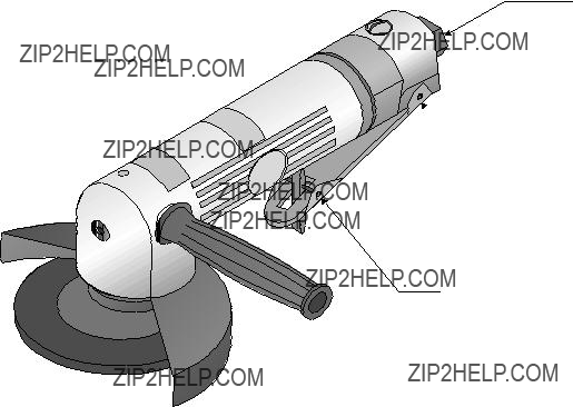
When unpacking your Air Angle Grinder, check the items against the list below. If any parts are missing or broken, please call Harbor Freight Tools at the number on the cover of this manual.
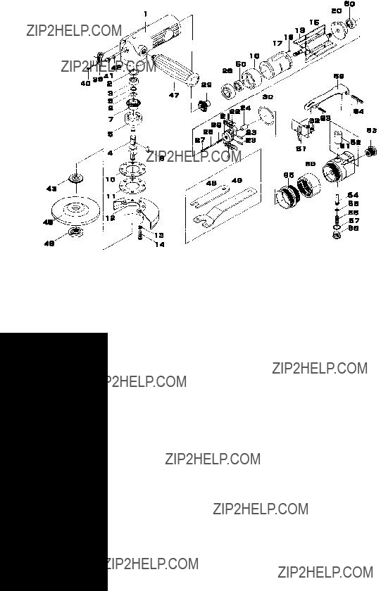
ASSEMBLY
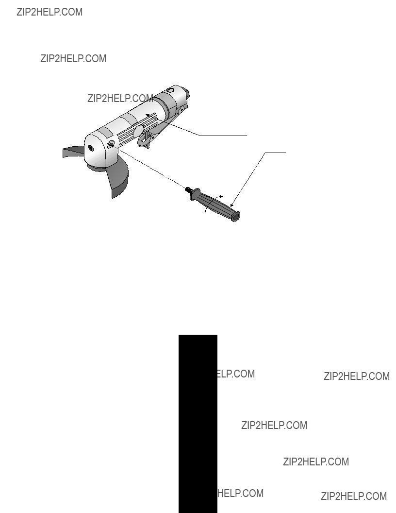
Step 1: Thread the HANDLE (#47) into the side of the Angle Grinder as shown in Figure 1. Tighten.
Angle Grinder Assembly
Handle (#47)
Figure 1 ??? Handle Assembly
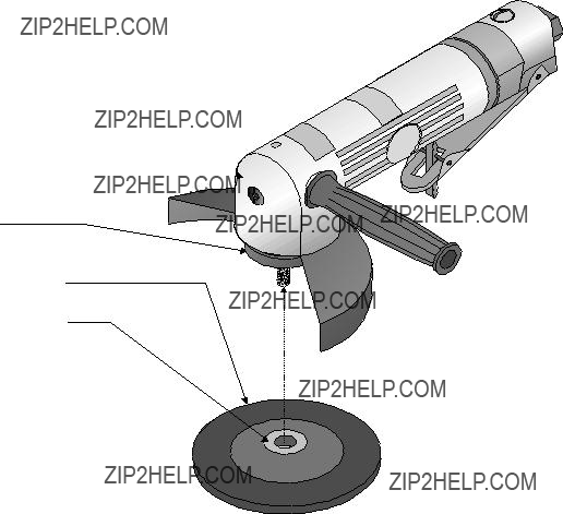
Step 2: Remove the FLANGE NUT (#46) from the ARBOR (#4).
Warning:
There are certain applications for which this tool was designed. Harbor Freight Tools strongly recommends that this tool not be modified and/or used for any application other than which it was designed.
All accessories must be rated for at least the RPM speed recommended on the tool???s warning label. Wheels and other accessories running over rated speed can fly apart and cause injury.
For safest operation, it is recommended that only these accessories be used with this product:
CAUTION: NEVER INSTALL A CARBIDE TIPPED OR STEEL CIRCULAR SAW
BLADE FOR USE ON THIS ANGLE GRINDER. NEVER INSTALL A WOOD CARVING
BLADE, CARVING DISC WITH SAW CHAIN CUTTERS, OR A CUTTING CARVING
DISC ON THIS ANGLE GRINDER.
Step 3: Place the GRINDING WHEEL (#45) onto the ARBOR with the Label side of the GRINDING WHEEL against the FLANGE (#43) as shown in Figure 2.
Angle Grinder Assembly
Flange (#43)
Grinding Wheel (#45)
Grinding Wheel Label
Figure 2 ??? Attaching the Grinding Wheel
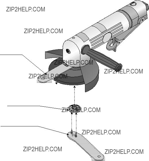
Step 4: Thread the FLANGE NUT (#46) onto the ARBOR. Tighten by hand.
Step 5: Place the WRENCH (#48) onto the flats of the ARBOR. You may have to turn the ARBOR slightly to fit the WRENCH on.
Step 6: Insert the prongs of the WRENCH (#49) into the two holes in the FLANGE NUT as shown in Figure 3.
Wrench (#48)
Grinding Wheel (#45)
Flange Nut (#46)
Wrench (#49)
Figure 3 ??? Securing the Grinding Wheel
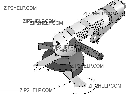
Step 7: Hold the flat WRENCH (#48) while tightening the angled WRENCH (#49) to tighten the Flange Nut as shown in Figure 4.
Wrench (#48)
Grinding Wheel (#45)
Wrench (#49)
Figure 4 ??? Tightening the Flange Nut
Step 8: Remove the WRENCHES.
Air Connection
Step 1: You will need a Union fitting (sold separately) before you can connect your Angle Grinder to an air compressor.
Step 2: Attach the Union fitting to the Angle Grinder and tighten.
Step 3: Attach an Air Coupler (sold separately) to the Union fitting if desired. This is a useful accessory as it allows quick-coupling action when using a variety of tools with the same air compressor.
Your Angle Grinder is ready for use.
OPERATION
Setup
Frequent, but not excessive, lubrication is required for best performance. Oil added through the airline connection will lubricate internal parts. An automatic airline oiler is recommended but oil may be added manually before every operation or after about 1 hour of continuous use. Only a few
drops of oil at a time are necessary. Too much oil will collect inside the tool and be blown out during the exhaust cycle. ONLY USE PNEUMATIC TOOL OIL. Do not use detergent oil or additives as these lubricants will cause accelerated wear to the seals in the tool.
Dirt and water in the air supply are major causes of pneumatic tool wear. Use a filter/oiler for better performance and longer life. The filter must have adequate flow capacity for the specific application. Consult the manufacturer???s instructions for proper maintenance of your filter.
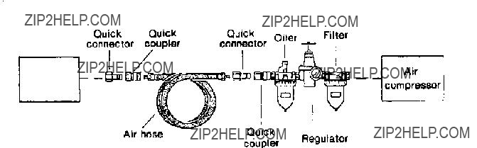
The connector on the tool must not hold pressure when the air supply is disconnected. If the wrong fitting is used, the tool can remain charged with air after being disconnected and still be able to drive a fastener. See Figure 5 for the recommended accessories and connection order.
Angle
Grinder
Figure 5 ??? Airline Oiler Assembly
Use
Step 1: Set the compressor???s pressure regulator to 90 PSI. Do not set the compressor???s outlet regulator over 90 PSI.
Step 2: Connect the Angle Grinder to the air compressor???s hose. If leaking is detected, discon- nect the air hose and repair before use.
Step 3: Identify the area you wish to grind. If possible, mark or scribe the area to ensure you grind accurately.
Step 4: If possible, place the grinding material into a vise or otherwise secure the material so it will not move.
Step 5: Grip the Angle Grinder with both hands. Make sure you are wearing eye protection and protective gloves before using the Angle Grinder.
Step 6: To operate the Angle Grinder, press the THROTTLE LEVER LOCK (#61) forward while depressing the THROTTLE LEVER (#59) as shown in Figure 6.
Throttle Lever (#59)
Throttle Lever Lock (#61)
Figure 6 ??? Operating the Angle Grinder
Step 7: Place the spinning GRINDING WHEEL (#45) onto the material to be ground. Let the weight of the Angle Grinder do the work. Do not press the Angle Grinder into the material. If the Angle Grinder stalls, release the THROTTLE LEVER immediately.
Step 8: Grind using the outside diameter of the GRINDING WHEEL as much as possible. Do not attempt to use the recessed inner diameter of the GRINDING wheel as you may damage the FLANGE NUT (#46).
MAINTENANCE
Your Angle Grinder is best operated with an Airline Oiler. If you are using the Angle Grinder without an Airline Oiler, follow the steps below for maintenance.
Step 1: Disconnect the Angle Grinder from the air hose.
Step 2: Apply a few drops of PNEUMATIC TOOL OIL through the air line before each use, or every hour if used continuously.
CAUTION
Do not use detergent oil or additives as these lubricants will cause accelerated wear to the seals in the tool.
Step 3: Apply a few drops of oil to the THROTTLE LEVER (#59) as shown in Figure 7. Work the THROTTLE LEVER a few times to lubricate.
Air Inlet
 Throttle Lever (#59)
Throttle Lever Lock (#61)
Figure 7 ??? Lubrication Points
Periodically check the condition of the GRINDING WHEEL (#45). If more than 1/2" of the GRINDING WHEEL is gone, or if the circular lines in the top of the GRINDING WHEEL are no longer visible, you must replace the GRINDING WHEEL with an approved replacement Wheel from Harbor Freight Tools.
PLEASE READ THE FOLLOWING CAREFULLY
THE MANUFACTURER AND/OR DISTRIBUTOR HAS PROVIDED THE PARTS LIST AND ASSEMBLY
DIAGRAM IN THIS MANUAL AS A REFERENCE TOOL ONLY. NEITHER THE MANUFACTURER OR
DISTRIBUTOR MAKES ANY REPRESENTATION OR WARRANTY OF ANY KIND TO THE BUYER
THAT HE OR SHE IS QUALIFIED TO MAKE ANY REPAIRS TO THE PRODUCT, OR THAT HE OR SHE
IS QUALIFIED TO REPLACE ANY PARTS OF THE PRODUCT. IN FACT, THE MANUFACTUER AND/
OR DISTRIBUTOR EXPRESSLY STATES THAT ALL REPAIRS AND PARTS REPLACEMENTS SHOULD
BE UNDERTAKEN BY CERTIFIED AND LICENSED TECHNICIANS, AND NOT BY THE BUYER. THE
BUYER ASSUMES ALL RISK AND LIABILITY ARISING OUT OF HIS OR HER REPAIRS TO THE
ORIGINAL PRODUCT OR REPLACEMENT PARTS THERETO, OR ARISING OUT OF HIS OR HER
INSTALLATION OF REPLACEMENT PARTS THERETO.
Page #11 -- SKU: 30304