Bicycle REPAIR STAND

WITH TOOL TRAY

Model 98579

Set up and Operating Instructions

Visit our website at: http://www.harborfreight.com

Read this material before using this product. Failure to do so can result in serious injury. Save this manual.

Copyright?? 2008 by Harbor Freight Tools??. All rights reserved. No portion of this manual or any artwork contained herein may be reproduced in any shape or form without the express written consent of Harbor Freight Tools. Diagrams within this manual may not be drawn proportionally. Due to continuing improvements, actual product may differ slightly from the product described herein. Tools required for assembly and service may not be included.

For technical questions or replacement parts, please call 1-800-444-3353.

Cover Revised 09l

Save This Manual

Keep this manual for the safety warnings and precautions, assembly, operating, inspection, maintenance and cleaning procedures. Write the product???s serial number in the back of the manual near the assembly diagram (or month and year of purchase if product has no number). Keep this manual and the receipt in a safe and dry place for future reference.

Important SAFETY

Information

In this manual, on the labeling, and all other information provided with this product:

This is the safety alert symbol. It is used to alert you to potential personal injury hazards. Obey all safety messages that follow this symbol to avoid possible injury or death.

DANGER indicates a hazardous situation which, if not avoided, will result

in death or serious injury.

WARNING indicates a hazardous situation

which, if not avoided, could result in death or serious injury.

CAUTION, used with the safety alert

symbol, indicates a hazardous situation which, if not avoided, could result in minor or moderate injury.

NOTICE is used to address practices not

related to personal injury.

CAUTION, without the safety alert symbol, is

used to address practices not related to personal injury.

Assembly Precautions

1.Assemble only according to these instructions. Improper assembly can create hazards.

2.Wear ANSI-approved safety goggles and heavy-duty work gloves during assembly.

3.Keep assembly area clean and well lit.

4.Keep bystanders out of the area during assembly.

5.Do not assemble when tired or when under the influence of drugs or medication.

Use Precautions

1.This product is not a toy. Do not allow children to play with or near this item.

2.Use as intended only. Do not use with electric or motorized bicycles. Do not use for aircraft purposes.

3.Wear ANSI-approved safety goggles and heavy-duty work gloves during use.

4.Inspect before every use; do not use if parts are loose or damaged.

5.Maintain product labels and nameplates.

These carry important safety information.

If unreadable or missing, contact Harbor

Freight Tools for a replacement.

6.Have your Stand serviced by a qualified repair person using only identical replacement parts. This will ensure that the safety of the Stand is maintained.

7.Only use the Stand on a flat, dry, level surface capable of supporting the weight of the Stand and its load.

8.Do not exceed the Stand???s maximum load capacity of 66 pounds. Beware of dynamic loading! Suddenly dropping load may create for a brief instance an excess load which may result in personal injury and/or property damage.

9.Do not move the Stand with a load attached. The Stand could tip over, resulting in personal injury and/or property damage.

10.Do not allow anyone to sit or stand on this Stand.

11.Do not leave the Stand unattended when it is under a load. Remove the load before leaving. Do not use to support loads for extended periods of time.

12.The warnings and instructions discussed in instruction manual cannot cover

all possible conditions and situations that may occur. It must be understood by operator that common sense and caution are factors which cannot be built into product, but must be supplied by operator.

Save these instructions.
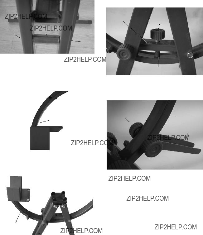
FIGURE A
NUT (9)
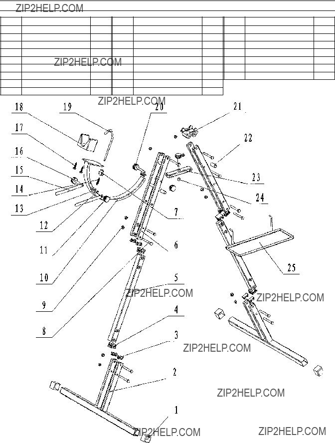
1. Attach the Leg (5) to the Foot (2), using two Bolts (8) and two Nuts (9). Repeat this procedure for the remaining Leg and
Foot. (See Figure A.)
FOOT (2)

Specifications

Unpacking

When unpacking, make sure that the item is intact and undamaged. If any parts are missing or broken, please call Harbor

Freight Tools at 1-800-444-3353 as soon as possible.

ASSEMBLY INSTRUCTIONS

Read the entire Important Safety Information section at the beginning of manual including all text under subheadings therein before set up or use of this product.

Note: For additional information regarding the parts listed in following pages, refer to

Assembly Diagram near end of manual.

LEG (5)

BOLT (8)

2.Attach the Head Bar (6) to end of the Leg (5), using two Bolts (8) and two Nuts (9).

Repeat this procedure for the remaining Head Bar and Leg. (See Figure B.)

FIGURE C

TOP

SADDLE (21)

HEAD

BAR (6)

3.Attach the Top Saddle (21) to both ends of the Head Bars (6), using four Bolts (8) and four Nuts (9). (See Figure C.)

FIGURE D

4. Attach the Connector (23) to the upper

FIGURE E

5.Attach the Protector (22) to the crossbeam of the Head Bar (6), using one Bolt (8) and one Nut (9). Repeat this procedure for the remaining Protector and Head Bar. (See Figure E.)

FIGURE H

CONNECTORKNOB

(23)BOLT (16)

Brake CAP (24)

8.Secure the Mounting Curve (10) in position, using one Knob Bolt (16) and one Brake Cap (24). (See Figure H.)

6.Attach the Adjustable Saddle (18) to the Mounting Curve (10), using two Screws (17). (See Figure F.)

FIGURE G

Mounting

Curve (10)

7.Position the Mounting Curve (10) as shown. (See Figure G.)

FIGURE I

Knob

Bolt (16)Mounting

Curve (10)

Front Wheel

Stabilizers (15)

Knob

NUT (11)

9.Attach the two Front Wheel Stabilizers

(15)to the Mounting Curve (10), using one Knob Nut (11) and one Knob Bolt

(16).(See Figure I.)

Mounting

Curve (10)

FIGURE J

10. Attach the Spring (14) to the Mounting

Curve (10), using one Socket Head

Screw (12) and one Spacer (13).

(See Figure J.)

CLAMP

KNOB (7)

Mounting

Curve (10)

11.Attach the Hook Clamp (19) to the

Mounting Curve (10). Attach the Clamp

Knob (7) to the Hook Clamp.

(See Figure K.)

SPRING (14)

12.Insert the end of the Spring (14) into the hole in the Hook Clamp (19).

(See Figure L.)

FIGURE M

TRAY (25)

13.Attach the Tray (25) to the two Head

Bars (6) as shown. (See Figure M.)

Operating Instructions

Read the entire Important Safety Information section at the beginning of this manual including all text under

subheadings therein before set up or use of this product.

1.Locate the Stand on a clean, dry, flat, and level surface capable of supporting the weight of the Stand, bicycle, bicycle parts, tools, etc.

FIGURE N

2.With assistance, set the bicycle on the

Stand, making sure the frame of the bicycle is resting on the Adjustable Saddle (18) and Top Saddle (21). Then adjust the Clamp Knob (7) so that the

Hook Clamp (19) fits tightly over the bicycle frame. (See Figures N and O.)

3.Swing the two Front Wheel Stabilizers

(15) next to the front wheel of the bicycle to limit its movement while you work on the bicycle.

FIGURE O

Knob

Bolt (16)

4.To swivel the bicycle upward or downward loosen the Knob Bolt (16).

Move the bicycle to the desired position. Then retighten the Knob Bolt.

(See Figure O.)

5.When finished repairing the bicycle, loosen the Clamp Knob (7) and remove the Hook Clamp (19) from the bicycle frame. With assistance, remove the bicycle from the Stand. (See Figure K.)

6.Store the Stand in a clean, dry, and safe location out of reach of children and other unauthorized persons.

Maintenance And

Servicing

Procedures not specifically explained in this manual must be performed only by a qualified technician.

To prevent serious injury

from accidental operation:

Remove any load from the Stand before performing any inspection, maintenance, or cleaning procedures.

1.BEFORE EACH USE, inspect the general condition of the Stand. Check for loose screws, misalignment or binding of moving parts, cracked or broken parts, and any other condition that may affect its safe operation.

2.PERIODICALLY: Lubricate all moving parts with a light grease or machine oil.

3.After Use, clean external surfaces of the Stand with clean cloth and mild detergent. Do not use solvents.

4.Store the Stand in a clean, dry, safe location out of reach of children and other unauthorized persons.

PLEASE READ THE

FOLLOWING CAREFULLY

The manufacturer and/or distributor has provided the parts list and assembly diagram in this manual as a reference tool only. Neither the manufacturer or distributor makes any representation or warranty of any kind to the buyer that he or she is qualified to make any repairs to the product, or that he or she is qualified to replace any parts of the product. In fact, the manufacturer and/ or distributor expressly states that all repairs and parts replacements should be undertaken by certified and licensed technicians, and not by the buyer. The buyer assumes all risk and liability arising out of his or her repairs to the original product or replacement parts thereto, or arising out of his or her installation of replacement parts thereto.

Record Product???s Serial Number Here:

__________________________________

Note: If product has no serial number, record month and year of purchase instead.

Note: Some parts are listed and shown for illustration purposes only, and are not available individually as replacement parts.

PARTS LIST & ASSEMBLY DIAGRAM