250 lb. Truck Ladder Rack

66187

Instructions and

precautions

Distributed exclusively by Harbor Freight Tools??.

3491 Mission Oaks Blvd., Camarillo, CA 93011

Visit our website at: http://www.harborfreight.com

Save these instructions. Read all precautions and instructions.

Copyright?? 2008 by Harbor Freight Tools??. All rights reserved. No portion of this document or any artwork contained herein may be reproduced in any shape or form without the express written consent of Harbor Freight Tools. Diagrams within this document may not be drawn proportionally. Due to continuing

improvements, actual product may differ slightly from the product described herein. Tools required for installation and service may not be included.

For technical questions or replacement parts, please call 1-800-444-3353.

Specifications

Unpacking

When unpacking, make sure that the item is intact and undamaged. If any parts are missing or broken, please call Harbor Freight Tools at 1-800-444-3353 as soon as possible.

Important SAFETY

Information

Installation Precautions

1.Follow DOT regulations regarding installation and use.

2.Verify that installation surface has no hidden utility lines before drilling or driving screws.

3.Install only according to these instructions. Improper installation can create hazards.

4.Wear ANSI-approved safety goggles and heavy-duty work gloves during installation.

5.Keep installation area clean and well lit.

6.Keep bystanders out of the area during installation.

7.Do not install when tired or when under the influence of drugs or medication.

Use Precautions

1.Do not exceed 250 lb. weight capacity, distributed evenly across both Frames. Be aware of dynamic loading! Sudden load movement may briefly create excess load causing product failure.

2.Strap ladder securely to rack.

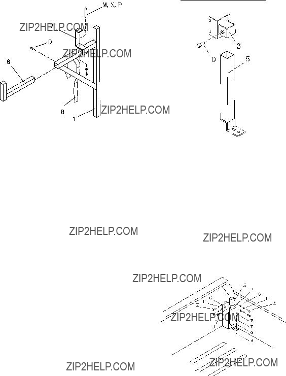
3.When expanding the Arm (6), leave at least 2.5??? of the tube in the Frame (1).

4.Use as intended only.

5.Inspect before every use; do not use if parts loose or damaged.

6.Maintain product labels and nameplates. These carry important safety information. If unreadable or missing, contact Harbor Freight Tools for a replacement.

Manual Revised 09b

Installation Instructions

Read the entire Important Safety Information section at the beginning of this document including all text under subheadings therein before set up or use of this product.

1.Park truck in level, stable location well away from traffic. Place transmission in park/neu- tral and set parking brake.

Blind Fastener (H) Installation

Blind Fasteners will need to be installed

2.WARNING! Verify that installation surface has no hidden brake lines, wiring, or other critical components before drilling.

3.Drill an 11 mm (0.433???) hole in the location the Blind Fastener will be installed.

4.Insert Blind Fastener so that the flange rests on the lip of the hole.

5.Thread Installation Bolt into Blind Fastener as far as possible. Hold Installation Bolt in place with one wrench while turning Installa- tion Nut (C) clockwise with another wrench until Blind Fastener is held securely in place.

6.Remove Installation Bolt from Blind Fastener.

Front Rack Installation

Note: The Front Rack is near the truck cab.

1.Slide Front Mounting Bracket (2) over Front Base (4) as shown above. Temporarily se- cure in place with Jam Bolt (D).

2.Place the Base/Bracket assembly as shown below at the passenger side of the vehicle near the cab. Loosen the Jam Bolt and allow the Base to slide down so the foot rests flat on the truck bed.

3.Mark the bedrail at center of the holes, 3 holes in the side and 1 hole on the truck bed. Any one of the 4 holes in the Base can be used for the truck bed hole. Set the assem- bly aside.

4.Drill for and install 4 Blind Fasteners (H) in the locations marked in the previous step.

(Truck ab) C

(Bed)

5.Attach the assembly to the Blind Fasteners as shown above using Bolts (E), Washers (F), and Spring Washers (G) - as shown

above.

Rear Rack Installation

6.Insert Arm (6) into Frame (1) and secure with Jam Bolt (D), as shown above.

7.Attach Ladder Stop (7) to Frame (1) using Carriage Bolt (M), Washer (N), and Nylon Insert Nut (P).

8.Install Strap (8) through the bracket on the Frame (1).

9.Slide the assembled Frame (1) into the Front Base (4).

1.Slide Rear Mounting Bracket (3) over Rear Base (5) as shown above. Temporarily se- cure in place with Jam Bolt (D).

2.Place the Base/Bracket assembly as shown below at the passenger side of the vehicle near the tailgate. Loosen the Jam Bolt and allow the Base to slide down so the foot rests flat on the truck bed.

3.Mark the bedrail at center of the holes, 4 holes in the side and 1 hole on the truck bed. Any one of the holes in the Base can be used for the truck bed hole. Set the assem- bly aside.

4.Drill for and install 5 Blind Fasteners (H) in the locations marked in the previous step.

(Bed)

(Tailgate)

5.Attach the assembly to the Blind Fasteners as shown above using Bolts (E), Washers (F), and Spring Washers (G) - as shown above.

6.Insert Arm (6) into Frame (1) and secure with Jam Bolt (D), as shown above.

7.Install Strap (8) through the bracket on the Frame (1).

8.Slide the assembled Frame (1) into the Rear Base (5).

After Installation

1.If desired, a Cleat (9) can be installed on each Frame (1). Place the Cleat in the de- sired location and mark the holes. Drill 1/4??? holes in the locations shown and install the Cleats, using Screws (J), Washers (K), and Nylon Insert Nuts (L).

2.Inspect and test vehicle systems thoroughly, especially lighting and braking systems, to confirm that they were not damaged during installation.

Operation

1.Measure the width of the ladder to be mount- ed on top of the Ladder Rack and slide the

Arms (6) to fit the ladder allowing no more than 2??? of space between ladder and Ladder Rack. Tighten the Jam Bolts (4) securely.

2.Lay the ladder on top of the Frames (1) between the vertical arms and slide it forward until it contacts the Ladder Stop (7).

3.Use the Straps (8) to wrap around ladder rungs and securely hold the ladder in place using hook and loop system attached to Straps.

Parts List and Diagram

Note: Some parts are listed and shown for illustra- tion purposes only, and are not available individually as replacement parts.

M

2

D E

A

F

BG

CH

4

5

8

J

K

N

L

P

1

9

Record Serial Number Here:

Note: If product has no serial number, record month and year of purchase instead.

PLEASE READ THE FOLLOWING

CAREFULLY

The manufacturer and/or distributor has provided the parts list and assembly diagram in this document as a reference tool only. Neither the manufacturer or distributor makes any representation or warranty of any kind to the buyer that he or she is qualified to make any repairs to the product, or that he or she is qualified to replace any parts of the product.

In fact, the manufacturer and/or distributor expressly states that all repairs and parts replacements should be undertaken by certified and licensed technicians, and not by the buyer. The buyer assumes all risk and liability arising out of his or her repairs to the original product or replacement parts thereto, or arising out of his or her installation of replacement parts thereto.

LIMITED 90 DAY WARRANTY

Harbor Freight Tools Co. makes every effort to assure that its products meet high quality and durability standards, and warrants to the original purchaser that this product is free from defects in materials and workmanship for the period of 90 days from the date of purchase. This warranty does not apply to damage due directly or indirectly, to misuse, abuse, negligence or accidents, repairs

or alterations outside our facilities, criminal activ- ity, improper installation, normal wear and tear, or to lack of maintenance. We shall in no event be liable for death, injuries to persons or property, or for incidental, contingent, special or consequential damages arising from the use of our product. Some states do not allow the exclusion or limitation of incidental or consequential damages, so the above limitation of exclusion may not apply to you. This warranty is expressly in lieu of all other warranties, express or implied, including the warranties of merchant- ability and fitness.

To take advantage of this warranty, the prod- uct or part must be returned to us with transporta- tion charges prepaid. Proof of purchase date and an explanation of the complaint must accompany the merchandise. If our inspection verifies the de- fect, we will either repair or replace the product at our election or we may elect to refund the purchase price if we cannot readily and quickly provide you with a replacement. We will return repaired prod- ucts at our expense, but if we determine there is no defect, or that the defect resulted from causes not within the scope of our warranty, then you must bear the cost of returning the product.

This warranty gives you specific legal rights and you may also have other rights which vary from state to state.

3491 Mission Oaks Blvd. ??? PO Box 6009 ??? Camarillo, CA 93011 ??? (800) 444-3353