COMPRESSION TESTER

WITH QUICK DISCONNECT

Model 92720

OPERATING INSTRUCTIONS

??

3491 Mission Oaks Blvd., Camarillo, CA 93011

Visit our Web site at: http://www.harborfreight.com

TO PREVENT SERIOUS INJURY,

READ AND UNDERSTAND ALL WARNINGS

AND INSTRUCTIONS BEFORE USE.

??

Copyright 2005 by Harbor Freight Tools?? . All rights reserved. No portion of this manual or any artwork contained herein may be reproduced in any shape or form without the express written consent of Harbor Freight Tools.

For technical questions or replacement parts, please call 1-800-444-3353.

Note: Accuracy of the Gauge is ?? 2%.

UNPACKING

When unpacking, check to make sure all the parts shown on the Parts Lists on page 8 are included. If any parts are missing or broken, please call Harbor Freight Tools at the number shown on the cover of this manual as soon as possible.

SAVE THIS MANUAL

You will need this manual for the safety warnings and precautions, assembly, operating, inspection, maintenance and cleaning procedures, parts list and assembly diagram. Keep your invoice with this manual. Write the invoice number on the inside of the front cover. Keep this manual and invoice in a safe and dry place for future reference.

GENERAL SAFETY PRECAUTIONS

WARNING!

READ AND UNDERSTAND ALL INSTRUCTIONS Failure to follow all instructions listed in the following pages may result in serious injury.

SAVE THESE INSTRUCTIONS

GENERAL SAFETY RULES

1.Keep your work area clean and well lit. Cluttered work areas invite accidents.

2.Do not operate tools and equipment in explosive atmospheres, such as in the presence of flammable liquids, gases, or dust. Tools and equipment create sparks which may ignite flammables.

3.Keep bystanders, children, and visitors away while operating tools and equipment. Distractions can cause you to lose control. Protect others in the work area. Provide barriers or shields as needed.

4.Stay alert. Watch what you are doing, and use common sense when oper- ating tools and equipment. Do not use tools and equipment while tired or under the influence of drugs, alcohol, or medication. A moment of inatten- tion while operating tools and equipment may result in serious personal injury.

5.Dress properly. Do not wear loose clothing or jewelry. Contain long hair. Keep your hair, clothing, and gloves away from moving parts. Loose clothes, jewelry, or long hair can be caught in moving parts.

6.Do not overreach. Keep proper footing and balance at all times. Proper footing and balance enables better control of the tool in unexpected situations.

7.Use safety equipment. Always wear ANSI approved safety impact goggles when using this product.

8.Do not force the tool. Use the correct tool for your application. The correct tool will do the job better and safer at the rate for which it is designed.

9.Store idle tools and equipment out of reach of children and other untrained persons. Tools and equipment are dangerous in the hands of untrained users.

10.Maintain tools with care. Do not use a damaged tool. Tag damaged tools ???Do not use??? until repaired.

11.If damaged, have the tool serviced before using. Check for loose screws, misalignment or binding of moving parts, loose mounting, cracked or broken parts, and any other condition that may affect its safe operation. Many accidents are caused by poorly maintained tools.

12.Use only accessories that are recommended by the manufacturer for your model. Accessories that may be suitable for one tool may become hazardous when used on another tool.

13.Tool service must be performed only by qualified repair personnel. Service or maintenance performed by unqualified personnel could result in a risk of injury.

14.When servicing a tool, use only identical replacement parts. Follow instructions in the ???Inspection, Maintenance, And Cleaning??? section of this manual. Use of unauthorized parts or failure to follow maintenance instructions may create a risk of injury.

SPECIFIC SAFETY RULES

1. WARNING! Do not exceed the maximum pressure capacity of this tool (300 PSI/20 BAR). Exceeding the maximum pressure capacity could cause serious personal injury and/or property damage.

2. WARNING! Use the Compression Tester only in well ventilated areas.

A running gasoline engine produces carbon monoxide. Carbon monoxide fumes are a colorless, odorless, gas that, if inhaled, can cause serious injury or death.

3.Maintain labels and nameplates on the Compression Tester. These carry

important information. If unreadable or missing, contact Harbor Freight Tools for

a replacement.

4.Prior to using the Compression Tester, make sure to read and understand all warnings, safety precautions, and instructions as outlined in the manufacturer???s instruction manual for the engine you will test.

5.When warming up an engine in preparation for compression testing, make sure the vehicle???s transmission is placed in ???PARK???, (or neutral for a manual transmission) and the emergency brake is applied.

6.Always keep hands and fingers away from the moving parts and hot parts of the vehicle???s engine.

7. WARNING! The brass components of this product contain lead, a chemi- cal known to the State of California to cause cancer and birth defects (or other reproductive harm). (California Health & Safety Code 25249.5 et seq.)

8. WARNING! People with pacemakers should consult their physician(s) before using this product. Electromagnetic fields in close proximity to a heart pacemaker could cause interference or failure of the pacemaker. In addition, people with pacemakers should adhere to the following: Caution is necessary when near the coil, spark plug cables, or distributor of a running engine. The engine should always be off if adjustments are to be made to the distributor.

9. WARNING! The warnings, precautions, and instructions discussed in this manual cannot cover all possible conditions and situations that may occur. The operator must understand that common sense and caution are factors, which cannot be built into this product, but must be supplied by the operator.

OPERATING INSTRUCTIONS

1.NOTE: Performing a compression test requires the work of two individuals; one person to operate the vehicle???s ignition switch while the other person operates the Compression Tester.

2.The Compression Tester features an Adapter Fitting (2) with its Rubber Cone that may be used on all types of spark plug holes and a Hose Fitting (4) that may be used for 14mm and 18mm spark plug holes. (See Figure A.)

3.To perform a typical compression test, prepare the engine for compression test- ing by starting the engine and allowing it to warm up to its normal operating temperature. Then, switch off the ignition. WARNING! Avoid carbon monoxide poisoning! Never run a gasoline engine in an enclosed garage or other contained area.

4.Once the engine has been turned off, disconnect both coil wires from the coil of the engine, and remove all of the spark plugs. Note: Insulate coil wires or route them away from each other and all metal surfaces. Make note of which spark plug wires go to each spark plug locations. (See Figures B and C, next page.)

GAUGE

(1)

HOSE FITTING

(4)

AIR RELEASE BUTTON

ADAPTER FITTING

(2)

HOSE

(3)

SKU 92720 For technical questions please call 1-800-444-3353 PAGE 5

5.Attach either the Adapter Fitting (2) or Hose (3) and Hose Fitting (4) to the Gauge (1). (See Figure A.)

6.Connect the Compression Tester to the first cylinder of the engine. With the fuel pedal depressed all the way down, crank the engine for at least eight revolutions.

(See Figure C.)

7.While cranking the engine, observe and record the maximum reading on the

Gauge (1) of the Compression Tester. (See Figure C.)

8.Once the maximum reading has been recorded, discontinue cranking the engine.

Then, release the air pressure in the Gauge (1) by pressing the Air Release

Button. (See Figure C.)

9.Remove the Compression Tester from the first engine cylinder. Then repeat

Steps #6, #7, #8 for the remaining engine cylinders. (See Figures B and C.)

10.NOTE: Good engine cylinder compression will be indicated with a high initial reading, and a progressive build-up to the final maximum reading. Poor engine cylinder compression will be indicated with a low initial reading, and a much slower build-up to the final maximum reading. The compression readings for all of the engine cylinders should not vary by more than 10%. Note: Check your owner???s or maintenance manual for acceptable pressure ranges.

COIL

COIL WIRES

FIGURE B

GAUGE

(1)

FIGURE C

INSPECTION, MAINTENANCE, AND CLEANING

1.Before each use, inspect the general condition of the Compression Tester. Check for broken, cracked, or bent parts, loose or missing parts, and any condi- tion that may affect the proper operation of the product. If a problem occurs, have the problem corrected before further use.

Do not use damaged equipment.

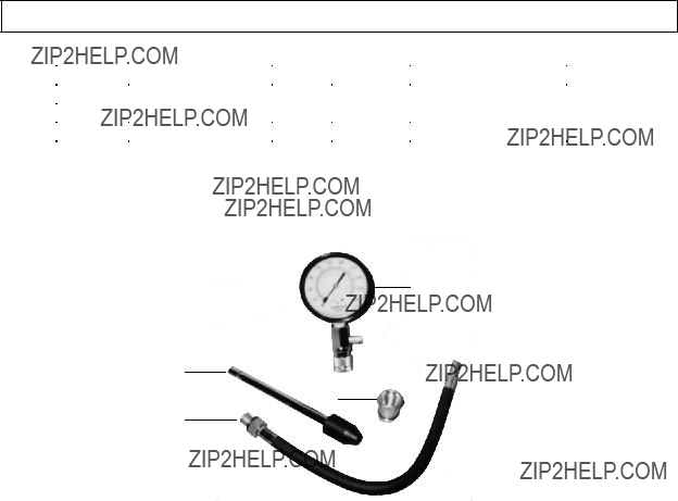
2.When cleaning, use a clean cloth with a mild detergent. Do not use solvents, as damage to the Compression Tester may result. Do not immerse the Gauge

(1) in any liquid. Then, store the Compression Tester in a safe, dry location out of reach of children and other unauthorized people.

3. CAUTION! All maintenance, service, or repairs not listed in this manual are only to be attempted by a qualified service technician.

PLEASE READ THE FOLLOWING CAREFULLY

THE MANUFACTURER AND/OR DISTRIBUTOR HAS PROVIDED THE PARTS LIST AND ASSEMBLY

DIAGRAM IN THIS MANUAL AS A REFERENCE TOOL ONLY. NEITHER THE MANUFACTURER OR

DISTRIBUTOR MAKES ANY REPRESENTATION OR WARRANTY OF ANY KIND TO THE BUYER THAT

HE OR SHE IS QUALIFIED TO MAKE ANY REPAIRS TO THE PRODUCT, OR THAT HE OR SHE IS

QUALIFIED TO REPLACE ANY PARTS OF THE PRODUCT. IN FACT, THE MANUFACTURER AND/OR

DISTRIBUTOR EXPRESSLY STATES THAT ALL REPAIRS AND PARTS REPLACEMENTS SHOULD BE

UNDERTAKEN BY CERTIFIED AND LICENSED TECHNICIANS, AND NOT BY THE BUYER. THE BUYER

ASSUMES ALL RISK AND LIABILITY ARISING OUT OF HIS OR HER REPAIRS TO THE ORIGINAL

PRODUCT OR REPLACEMENT PARTS THERETO, OR ARISING OUT OF HIS OR HER INSTALLATION

OF REPLACEMENT PARTS THERETO.

SKU 92720 For technical questions please call 1-800-444-3353 PAGE 7

PARTS LIST / ASSEMBLY DIAGRAM

1

2

4

3

5: CARRYING CASE NOT SHOWN.

NOTE:

Some parts are listed and shown for illustration purposes only, and are not available individually as replacement parts.