Twin tank 2 HP air compressor
65410
Set up and Operating Instructions
Visit our website at: http://www.harborfreight.com
Read this material before using this product. Failure to do so can result in serious injury. Save this manual.
Copyright?? 2008 by Harbor Freight Tools??. All rights reserved. No portion of this manual or any artwork contained herein may be reproduced in any shape or form without the express written consent of Harbor Freight Tools. Diagrams within this manual may not be drawn proportionally. Due to continuing improvements, actual product may differ slightly from the product described herein. Tools required for assembly and service may not be included.
For technical questions or replacement parts, please call 1-800-444-3353.

rupter (GFCI) should also be imple- mented ??? it prevents sustained elec- trical shock.
13.Some dust created by power sand- ing, sawing, grinding, drilling, and other construction activities, contains chemicals known [to the State of Cali- fornia] to cause cancer, birth defects or other reproductive harm. Some examples of these chemicals are:
???Lead from lead-based paints
???Crystalline silica from bricks and ce- ment or other masonry products
???Arsenic and chromium from chemi- cally treated lumber
Your risk from these exposures var- ies, depending on how often you do this type of work. To reduce your exposure to these chemicals: work in a well ventilated area, and work with approved safety equipment, such as those dust masks that are specially designed to filter out microscopic particles. (California Health & Safety Code ?? 25249.5, et seq.)
Save these instructions.
Grounding
To prevent electric shock
and death from incorrect grounding wire connection:
Check with a qualified electrician if you are in doubt as to whether the outlet is properly grounded. Do not modify the power cord plug provided with the tool. Never remove the grounding prong from the plug. Do not use the tool if the power cord or plug is damaged. If damaged, have it repaired by a service facility before use. If the plug will not fit the outlet, have a proper outlet installed by a qualified electrician.
14.WARNING: Handling the cord on
this product will expose you to lead, Grounded Tools: Tools with Three
a chemical known to the State of
California to cause cancer, and birth defects or other reproductive harm. Wash hands after handling. (Califor- nia Health & Safety Code ?? 25249.5, et seq.)
15.The warnings, precautions, and in- structions discussed in this instruction manual cannot cover all possible con- ditions and situations that may occur.
It must be understood by the operator that common sense and caution are factors which cannot be built into this product, but must be supplied by the operator.
Prong Plugs
1.Tools marked with ???Grounding Re- quired??? have a three wire cord and three prong grounding plug. The plug must be connected to a properly grounded outlet. If the tool should
electrically malfunction or break down, grounding provides a low resistance path to carry electricity away from the user, reducing the risk of electric shock. (See 3-Prong Plug and Outlet.)
2.The grounding prong in the plug is connected through the green wire in- side the cord to the grounding system in the tool. The green wire in the cord must be the only wire connected to the tool???s grounding system and must never be attached to an electrically
???live??? terminal. (See 3-Prong Plug and Outlet.)
3.The tool must be plugged into an appropriate outlet, properly installed and grounded in accordance with all codes and ordinances. The plug and outlet should look like those in the preceding illustration. (See 3-Prong
Plug and Outlet.)
Symbology
n0 xxxx/min. No Load Revolutions per Minute
(RPM)
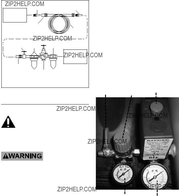
to properly power the tool, but the output will not exceed the tool???s maximum air pressure at any time. Turn the knob clockwise to increase pressure and counter-clockwise to decrease pressure. Adjust the pres- sure gradually, while checking the air output gauge to set the right pressure range.
10.The Air Compressor will cycle up to 115 PSI before shutting off. It will start to build pressure again when the
PSI of the Compressor drops to 85
PSI.
11.After the job is complete, move the Power Switch to the OFF position.
12.Close the Pressure Valve.
13.Pull down on the Safety Valve under- neath the Gauges to release pres- sure. Squeeze the Trigger of the air tool to release pressure from the line
Drain Valve
15.Disconnect the air hose and tool.
16.To prevent accidents, disconnect its power supply after use. Clean, then store the tool indoors out of children???s reach.
Safety Valve (51)
14.Turn the Drain Valve at the bottom of the Tank two turns to release any built-up moisture. Close the valve after moisture has drained out. Do not remove the Drain Valve.
Troubleshooting
Follow all safety precautions whenever diagnosing or servicing the tool. Disconnect air supply before service.

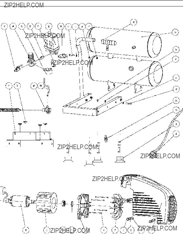
PartDescription
1Cowl
2Spring Washer
3Washer
4Pan Head Screw M5x14
5Fan
6Screw M5x15
7Motor Rear Cover
8Wave Washer
9Bearing
10Stator Assembly
11Rotor Assembly
12Capacitor
13Bearing
14Oil Seal
15Nut M8
16Crankcase
17Crank
18Screw M8x16
19Crankcase Gasket
20Crankcase Cover
21Oil Leveler
22Hex Head Screw
23Pan Head Screw M6x14
24Breather Assembly
25Spring Washer 8
26Washer 8
27Screw M6x14
28Connecting Rod
29Piston
30Circlip 12
31Piston Pin
32Cylinder Gasket
33Cylinder
34Spring Washer 6
35Washer 6
36Screw M6x40
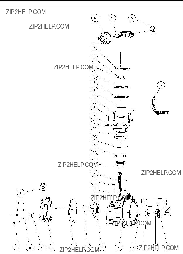
PartDescription
37Oil Gasket
38Seal Ring
39Valve Plate Gasket
40Valve Plate Assembly
41Air Intake Valve
42Limit Pin
43Cylinder Head Gasket
44Air Filter
45Cylinder Head
46Elbow Connector
47Coupler
48Pressure Regulator
49Tool Pressure Gauge
50Connector
51Safety Valve Assembly
52Pressure Switch Assembly
53Tank Pressure Gauge
54Hex Head Screw M6x25
55Washer 6
56Washer 6
57Nut M6
58Tank Assembly
59Nut M8
60Washer 8
61Handle Sleeve
62Washer 8
63Hex Head Screw M8x40
64Drain Valve
65Nut
66Rubber Foot
67Cord/Plug
68Pipe Assembly
69Check Valve Assembly
70Rear Motor Cover Gasket
71Frame Assembly
72Exhaust Pipe
Record Product???s Serial Number Here:
Note: If product has no serial number, record month and year of purchase instead.
Note: Some parts are listed and shown for illustration purposes only, and are not avail- able individually as replacement parts.
ASSEMBLY DIAGRAM, continued

Limited 1 year / 90 day Warranty
Harbor Freight Tools Co. makes every effort to assure that its products meet high quality and durability standards, and warrants to the original purchaser that for a period of one year from date of purchase that the tank is free of defects in materials and work- manship (90 days if used by a professional contractor or if used as rental equipment).
Harbor Freight Tools also warrants to the original purchaser, for a period of ninety days from date of purchase, that all other parts and components of the product are free from defects in materials and workmanship. This warranty does not apply to damage due di- rectly or indirectly to misuse, abuse, negligence or accidents, repairs or alterations out- side our facilities, normal wear and tear, or to lack of maintenance. We shall in no event be liable for death, injuries to persons or property, or for incidental, contingent, special or consequential damages arising from the use of our product. Some states do not allow the exclusion or limitation of incidental or consequential damages, so the above limita- tion of exclusion may not apply to you. This warranty is expressly in lieu of all other warranties, express or implied, including the warranties of merchantability and fitness.
To take advantage of this warranty, the product or part must be returned to us with transportation charges prepaid. Proof of purchase date and an explanation of the com- plaint must accompany the merchandise. If our inspection verifies the defect, we will ei- ther repair or replace the product at our election or we may elect to refund the purchase price if we cannot readily and quickly provide you with a replacement. We will return re- paired products at our expense, but if we determine there is no defect, or that the defect resulted from causes not within the scope of our warranty, then you must bear the cost of returning the product.
This warranty gives you specific legal rights and you may also have other rights which vary from state to state.
3491 Mission Oaks Blvd. ??? PO Box 6009 ??? Camarillo, CA 93011 ??? (800) 444-3353


 WARNING! If the supply cord of this power tool is damaged, it must