HP ProLiant ML370 Generation 5 Server
Maintenance and Service Guide
Part Number
October 2008 (Ninth Edition)
HP ProLiant ML370 Generation 5 Server
Maintenance and Service Guide
Part Number
October 2008 (Ninth Edition)
?? Copyright 2006, 2008
The information contained herein is subject to change without notice. The only warranties for HP products and services are set forth in the express warranty statements accompanying such products and services. Nothing herein should be construed as constituting an additional warranty. HP shall not be liable for technical or editorial errors or omissions contained herein.
Microsoft, Windows, Windows Server and Windows NT are U.S. registered trademarks of Microsoft Corporation.
Intel and Xeon are trademarks or registered trademarks of Intel Corporation or its subsidiaries in the United States and other countries.
Intended audience
This guide is for an experienced service technician. HP assumes you are qualified in the servicing of computer equipment and trained in recognizing hazards in products with hazardous energy levels and are familiar with weight and stability precautions for rack installations.

Contents
Contents 5

Customer self repair
HP products are designed with many Customer Self Repair (CSR) parts to minimize repair time and allow for greater flexibility in performing defective parts replacement. If during the diagnosis period HP (or HP service providers or service partners) identifies that the repair can be accomplished by the use of a CSR part, HP will ship that part directly to you for replacement. There are two categories of CSR parts:
???
???
NOTE: Some HP parts are not designed for customer self repair. In order to satisfy the customer warranty, HP requires that an authorized service provider replace the part. These parts are identified as "No" in the Illustrated Parts Catalog.
Based on availability and where geography permits, CSR parts will be shipped for next business day delivery. Same day or
For more information about HP's Customer Self Repair program, contact your local service provider. For the North American program, refer to the HP website (http://www.hp.com/go/selfrepair).
Parts only warranty service
Your HP Limited Warranty may include a parts only warranty service. Under the terms of parts only warranty service, HP will provide replacement parts free of charge.
For parts only warranty service, CSR part replacement is mandatory. If you request HP to replace these parts, you will be charged for the travel and labor costs of this service.
R??paration par le client (CSR)
Les produits HP comportent de nombreuses pi??ces CSR (Customer Self Repair = r??paration par le client) afin de minimiser les d??lais de r??paration et faciliter le remplacement des pi??ces d??fectueuses. Si pendant la p??riode de diagnostic, HP (ou ses partenaires ou mainteneurs agr????s) d??termine que la r??paration peut ??tre effectu??e ?? l'aide d'une pi??ce CSR, HP vous l'envoie directement. Il existe deux cat??gories de pi??ces CSR:
Customer self repair 6
???Obligatoire - Pi??ces pour lesquelles la r??paration par le client est obligatoire. Si vous demandez ?? HP de remplacer ces pi??ces, les co??ts de d??placement et main d'??uvre du service vous seront factur??s.
???Facultatif - Pi??ces pour lesquelles la r??paration par le client est facultative. Ces pi??ces sont ??galement con??ues pour permettre au client d'effectuer
REMARQUE: Certaines pi??ces HP ne sont pas con??ues pour permettre au client d'effectuer
Les pi??ces CSR sont livr??es le jour ouvr?? suivant, dans la limite des stocks disponibles et selon votre situation g??ographique. Si votre situation g??ographique le permet et que vous demandez une livraison le jour m??me ou dans les 4 heures,
Pour plus d'informations sur le programme CSR de HP, contactez votre Mainteneur Agr??e local. Pour plus d'informations sur ce programme en Am??rique du Nord, consultez le site Web HP (http://www.hp.com/go/selfrepair).
Service de garantie "pi??ces seules"
Votre garantie limit??e HP peut inclure un service de garantie "pi??ces seules". Dans ce cas, les pi??ces de rechange fournies par HP ne sont pas factur??es.
Dans le cadre de ce service, la r??paration des pi??ces CSR par le client est obligatoire. Si vous demandez ?? HP de remplacer ces pi??ces, les co??ts de d??placement et main d'??uvre du service vous seront factur??s.
Riparazione da parte del cliente
Per abbreviare i tempi di riparazione e garantire una maggiore flessibilit?? nella sostituzione di parti difettose, i prodotti HP sono realizzati con numerosi componenti che possono essere riparati direttamente dal cliente (CSR, Customer Self Repair). Se in fase di diagnostica HP (o un centro di servizi o di assistenza HP) identifica il guasto come riparabile mediante un ricambio CSR, HP lo spedir?? direttamente al cliente per la sostituzione. Vi sono due categorie di parti CSR:
???Obbligatorie ??? Parti che devono essere necessariamente riparate dal cliente. Se il cliente ne affida la riparazione ad HP, deve sostenere le spese di spedizione e di manodopera per il servizio.
???Opzionali ??? Parti la cui riparazione da parte del cliente ?? facoltativa. Si tratta comunque di componenti progettati per questo scopo. Se tuttavia il cliente ne richiede la sostituzione ad HP, potrebbe dover sostenere spese addizionali a seconda del tipo di garanzia previsto per il prodotto.
Customer self repair 7
NOTA: alcuni componenti HP non sono progettati per la riparazione da parte del cliente. Per rispettare la garanzia, HP richiede che queste parti siano sostituite da un centro di assistenza autorizzato. Tali parti sono identificate da un "No" nel Catalogo illustrato dei componenti.
In base alla disponibilit?? e alla localit?? geografica, le parti CSR vengono spedite con consegna entro il giorno lavorativo seguente. La consegna nel giorno stesso o entro quattro ore ?? offerta con un supplemento di costo solo in alcune zone. In caso di necessit?? si pu?? richiedere l'assistenza telefonica di un addetto del centro di supporto tecnico HP. Nel materiale fornito con una parte di ricambio CSR, HP specifica se il cliente deve restituire dei componenti. Qualora sia richiesta la resa ad HP del componente difettoso, lo si deve spedire ad HP entro un determinato periodo di tempo, generalmente cinque (5) giorni lavorativi. Il componente difettoso deve essere restituito con la documentazione associata nell'imballo di spedizione fornito. La mancata restituzione del componente pu?? comportare la fatturazione del ricambio da parte di HP. Nel caso di riparazione da parte del cliente, HP sostiene tutte le spese di spedizione e resa e sceglie il corriere/vettore da utilizzare.
Per ulteriori informazioni sul programma CSR di HP contattare il centro di assistenza di zona. Per il programma in Nord America fare riferimento al sito Web HP (http://www.hp.com/go/selfrepair).
Servizio di garanzia per i soli componenti
La garanzia limitata HP pu?? includere un servizio di garanzia per i soli componenti. Nei termini di garanzia del servizio per i soli componenti, HP fornir?? gratuitamente le parti di ricambio.
Per il servizio di garanzia per i soli componenti ?? obbligatoria la formula CSR che prevede la riparazione da parte del cliente. Se il cliente invece richiede la sostituzione ad HP, dovr?? sostenere le spese di spedizione e di manodopera per il servizio.
Customer Self Repair
HP Produkte enthalten viele
???Zwingend ??? Teile, f??r die das Customer Self
???Optional ??? Teile, f??r die das Customer Self
HINWEIS: Einige Teile sind nicht f??r Customer Self Repair ausgelegt. Um den Garantieanspruch des Kunden zu erf??llen, muss das Teil von einem HP Servicepartner ersetzt werden. Im illustrierten Teilekatalog sind diese Teile mit ???No??? bzw. ???Nein??? gekennzeichnet.
Customer self repair 8
anrufen und sich von einem Mitarbeiter per Telefon helfen lassen. Den Materialien, die mit einem CSR- Ersatzteil geliefert werden, k??nnen Sie entnehmen, ob das defekte Teil an HP zur??ckgeschickt werden muss. Wenn es erforderlich ist, das defekte Teil an HP zur??ckzuschicken, m??ssen Sie dies innerhalb eines vorgegebenen Zeitraums tun, in der Regel innerhalb von f??nf (5) Gesch??ftstagen. Das defekte Teil muss mit der zugeh??rigen Dokumentation in der Verpackung zur??ckgeschickt werden, die im Lieferumfang enthalten ist. Wenn Sie das defekte Teil nicht zur??ckschicken, kann HP Ihnen das Ersatzteil in Rechnung stellen. Im Falle von Customer Self Repair kommt HP f??r alle Kosten f??r die Lieferung und R??cksendung auf und bestimmt den
Weitere Informationen ??ber das HP Customer Self Repair Programm erhalten Sie von Ihrem Servicepartner vor Ort. Informationen ??ber das
Ihre HP Garantie umfasst m??glicherweise einen
F??r den
Reparaciones del propio cliente
Los productos de HP incluyen muchos componentes que el propio usuario puede reemplazar (Customer Self Repair, CSR) para minimizar el tiempo de reparaci??n y ofrecer una mayor flexibilidad a la hora de realizar sustituciones de componentes defectuosos. Si, durante la fase de diagn??stico, HP (o los proveedores o socios de servicio de HP) identifica que una reparaci??n puede llevarse a cabo mediante el uso de un componente CSR, HP le enviar?? dicho componente directamente para que realice su sustituci??n. Los componentes CSR se clasifican en dos categor??as:
???Obligatorio: componentes para los que la reparaci??n por parte del usuario es obligatoria. Si solicita a HP que realice la sustituci??n de estos componentes, tendr?? que hacerse cargo de los gastos de desplazamiento y de mano de obra de dicho servicio.
???Opcional: componentes para los que la reparaci??n por parte del usuario es opcional. Estos componentes tambi??n est??n dise??ados para que puedan ser reparados por el usuario. Sin embargo, si precisa que HP realice su sustituci??n, puede o no conllevar costes adicionales, dependiendo del tipo de servicio de garant??a correspondiente al producto.
NOTA: Algunos componentes no est??n dise??ados para que puedan ser reparados por el usuario. Para que el usuario haga valer su garant??a, HP pone como condici??n que un proveedor de servicios autorizado realice la sustituci??n de estos componentes. Dichos componentes se identifican con la palabra "No" en el cat??logo ilustrado de componentes.
Seg??n la disponibilidad y la situaci??n geogr??fica, los componentes CSR se enviar??n para que lleguen a su destino al siguiente d??a laborable. Si la situaci??n geogr??fica lo permite, se puede solicitar la entrega en el mismo d??a o en cuatro horas con un coste adicional. Si precisa asistencia t??cnica, puede llamar al
Customer self repair 9
Centro de asistencia t??cnica de HP y recibir?? ayuda telef??nica por parte de un t??cnico. Con el env??o de materiales para la sustituci??n de componentes CSR, HP especificar?? si los componentes defectuosos deber??n devolverse a HP. En aquellos casos en los que sea necesario devolver alg??n componente a HP, deber?? hacerlo en el periodo de tiempo especificado, normalmente cinco d??as laborables. Los componentes defectuosos deber??n devolverse con toda la documentaci??n relacionada y con el embalaje de env??o. Si no enviara el componente defectuoso requerido, HP podr?? cobrarle por el de sustituci??n. En el caso de todas sustituciones que lleve a cabo el cliente, HP se har?? cargo de todos los gastos de env??o y devoluci??n de componentes y escoger?? la empresa de transporte que se utilice para dicho servicio.
Para obtener m??s informaci??n acerca del programa de Reparaciones del propio cliente de HP, p??ngase en contacto con su proveedor de servicios local. Si est?? interesado en el programa para Norteam??rica, visite la p??gina web de HP siguiente (http://www.hp.com/go/selfrepair).
Servicio de garant??a exclusivo de componentes
La garant??a limitada de HP puede que incluya un servicio de garant??a exclusivo de componentes. Seg??n las condiciones de este servicio exclusivo de componentes, HP le facilitar?? los componentes de repuesto sin cargo adicional alguno.
Para este servicio de garant??a exclusivo de componentes, es obligatoria la sustituci??n de componentes por parte del usuario (CSR). Si solicita a HP que realice la sustituci??n de estos componentes, tendr?? que hacerse cargo de los gastos de desplazamiento y de mano de obra de dicho servicio.
Customer Self Repair
Veel onderdelen in HP producten zijn door de klant zelf te repareren, waardoor de reparatieduur tot een minimum beperkt kan blijven en de flexibiliteit in het vervangen van defecte onderdelen groter is. Deze onderdelen worden
???Verplicht: Onderdelen waarvoor reparatie door de klant verplicht is. Als u HP verzoekt deze onderdelen voor u te vervangen, worden u voor deze service reiskosten en arbeidsloon in rekening gebracht.
???Optioneel: Onderdelen waarvoor reparatie door de klant optioneel is. Ook deze onderdelen zijn ontworpen voor reparatie door de klant. Als u echter HP verzoekt deze onderdelen voor u te vervangen, kunnen daarvoor extra kosten in rekening worden gebracht, afhankelijk van het type garantieservice voor het product.
OPMERKING: Sommige HP onderdelen zijn niet ontwikkeld voor reparatie door de klant. In verband met de garantievoorwaarden moet het onderdeel door een geautoriseerde Service Partner worden vervangen. Deze onderdelen worden in de ge??llustreerde onderdelencatalogus aangemerkt met "Nee".
Afhankelijk van de leverbaarheid en de locatie worden
Customer self repair 10
periode, gewoonlijk vijf (5) werkdagen, retourneren aan HP. Het defecte onderdeel moet met de bijbehorende documentatie worden geretourneerd in het meegeleverde verpakkingsmateriaal. Als u het defecte onderdeel niet terugzendt, kan HP u voor het vervangende onderdeel kosten in rekening brengen. Bij reparatie door de klant betaalt HP alle verzendkosten voor het vervangende en geretourneerde onderdeel en kiest HP zelf welke koerier/transportonderneming hiervoor wordt gebruikt.
Neem contact op met een Service Partner voor meer informatie over het Customer Self Repair programma van HP. Informatie over Service Partners vindt u op de HP website (http://www.hp.com/go/selfrepair).
Garantieservice "Parts Only"
Het is mogelijk dat de HP garantie alleen de garantieservice "Parts Only" omvat. Volgens de bepalingen van de Parts Only garantieservice zal HP kosteloos vervangende onderdelen ter beschikking stellen.
Voor de Parts Only garantieservice is vervanging door
Reparo feito pelo cliente
Os produtos da HP s??o projetados com muitas pe??as para reparo feito pelo cliente (CSR) de modo a minimizar o tempo de reparo e permitir maior flexibilidade na substitui????o de pe??as com defeito. Se, durante o per??odo de diagn??stico, a HP (ou fornecedores/parceiros de servi??o da HP) concluir que o reparo pode ser efetuado pelo uso de uma pe??a CSR, a pe??a de reposi????o ser?? enviada diretamente ao cliente. Existem duas categorias de pe??as CSR:
???Obrigat??ria ??? Pe??as cujo reparo feito pelo cliente ?? obrigat??rio. Se desejar que a HP substitua essas pe??as, ser??o cobradas as despesas de transporte e
???Opcional ??? Pe??as cujo reparo feito pelo cliente ?? opcional. Essas pe??as tamb??m s??o projetadas para o reparo feito pelo cliente. No entanto, se desejar que a HP as substitua, pode haver ou n??o a cobran??a de taxa adicional, dependendo do tipo de servi??o de garantia destinado ao produto.
OBSERVA????O: Algumas pe??as da HP n??o s??o projetadas para o reparo feito pelo cliente. A fim de cumprir a garantia do cliente, a HP exige que um t??cnico autorizado substitua a pe??a. Essas pe??as est??o identificadas com a marca "No" (N??o), no cat??logo de pe??as ilustrado.
Conforme a disponibilidade e o local geogr??fico, as pe??as CSR ser??o enviadas no primeiro dia ??til ap??s o pedido. Onde as condi????es geogr??ficas permitirem, a entrega no mesmo dia ou em quatro horas pode ser feita mediante uma taxa adicional. Se precisar de aux??lio, entre em contato com o Centro de suporte t??cnico da HP para que um t??cnico o ajude por telefone. A HP especifica nos materiais fornecidos com a pe??a CSR de reposi????o se a pe??a com defeito deve ser devolvida ?? HP. Nos casos em que isso for necess??rio, ?? preciso enviar a pe??a com defeito ?? HP dentro do per??odo determinado, normalmente cinco (5) dias ??teis. A pe??a com defeito deve ser enviada com a documenta????o correspondente no material de transporte fornecido. Caso n??o o fa??a, a HP poder?? cobrar a reposi????o. Para as pe??as de reparo feito pelo cliente, a HP paga todas as despesas de transporte e de devolu????o da pe??a e determina a transportadora/servi??o postal a ser utilizado.
Para obter mais informa????es sobre o programa de reparo feito pelo cliente da HP, entre em contato com o fornecedor de servi??os local. Para o programa
Customer self repair 11
Servi??o de garantia apenas para pe??as
A garantia limitada da HP pode incluir um servi??o de garantia apenas para pe??as. Segundo os termos do servi??o de garantia apenas para pe??as, a HP fornece as pe??as de reposi????o sem cobrar nenhuma taxa.
No caso desse servi??o, a substitui????o de pe??as CSR ?? obrigat??ria. Se desejar que a HP substitua essas pe??as, ser??o cobradas as despesas de transporte e
Customer self repair 12

Customer self repair 13

Customer self repair 14
Customer self repair 15

Customer self repair 16
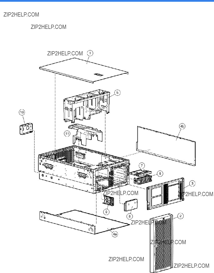
Illustrated parts catalog
Mechanical components
Illustrated parts catalog 17
*Not shown
1Mandatory:
2Optional:
3No:
1Mandatory:
2Optional:
3No: Non
Illustrated parts catalog 18
1Mandatory:
3No:
1Mandatory:
2Optional: Opcional??? componentes para los que la reparaci??n por parte del usuario es opcional. Estos componentes tambi??n est??n dise??ados para que puedan ser reparados por el usuario. Sin embargo, si precisa que HP realice su sustituci??n, puede o no conllevar costes adicionales, dependiendo del tipo de servicio de garant??a correspondiente al producto.
3No:
1Mandatory:
2Optional:
1Mandatory:
2Optional:
3No:
Illustrated parts catalog 19
Illustrated parts catalog 20
System components
Illustrated parts catalog 21


* Not shown
???Do not mix
Illustrated parts catalog 25
1Mandatory:
2Optional:
3No:
1Mandatory:
2Optional:
3No: Non
1Mandatory:
3No:
1Mandatory:
2Optional: Opcional??? componentes para los que la reparaci??n por parte del usuario es opcional. Estos componentes tambi??n est??n dise??ados para que puedan ser reparados por el usuario. Sin embargo, si precisa que HP realice su sustituci??n, puede o no conllevar costes adicionales, dependiendo del tipo de servicio de garant??a correspondiente al producto.
3No:
1Mandatory:
2Optional:
1Mandatory:
2Optional:
Illustrated parts catalog 26
3No:
Illustrated parts catalog 27

Removal and replacement procedures
Required tools
You need the following items for some procedures:
???
???Diagnostics Utility (included on the SmartStart
Safety considerations
Before performing service procedures, review all the safety information.
Preventing electrostatic discharge
To prevent damaging the system, be aware of the precautions you need to follow when setting up the system or handling parts. A discharge of static electricity from a finger or other conductor may damage system boards or other
To prevent electrostatic damage:
???Avoid hand contact by transporting and storing products in
???Keep
???Place parts on a grounded surface before removing them from their containers.
???Avoid touching pins, leads, or circuitry.
???Always be properly grounded when touching a
Symbols on equipment
The following symbols may be placed on equipment to indicate the presence of potentially hazardous conditions.
This symbol indicates the presence of hazardous energy circuits or electric shock hazards. Refer all servicing to qualified personnel.
WARNING: To reduce the risk of injury from electric shock hazards, do not open this enclosure. Refer all maintenance, upgrades, and servicing to qualified personnel.
This symbol indicates the presence of electric shock hazards. The area contains no user or field serviceable parts. Do not open for any reason.
WARNING: To reduce the risk of injury from electric shock hazards, do not open this enclosure.
Removal and replacement procedures 28

Rack warnings
This symbol on an
WARNING: To reduce the risk of electric shock, fire, or damage to the equipment, do not plug telephone or telecommunications connectors into this receptacle.
This symbol indicates the presence of a hot surface or hot component. If this surface is contacted, the potential for injury exists.
WARNING: To reduce the risk of injury from a hot component, allow the surface to cool before touching.
This symbol indicates that the component exceeds the recommended weight for one individual to handle safely.
WARNING: To reduce the risk of personal injury or damage to the equipment, observe local occupational health and safety requirements and guidelines for manual material handling.
These symbols, on power supplies or systems, indicate that the equipment is supplied by multiple sources of power.
WARNING: To reduce the risk of injury from electric shock, remove all power cords to completely disconnect power from the system.
WARNING: To reduce the risk of personal injury or damage to the equipment, be sure that:
???The leveling jacks are extended to the floor.
???The full weight of the rack rests on the leveling jacks.
???The stabilizing feet are attached to the rack if it is a
???The racks are coupled together in
???Only one component is extended at a time. A rack may become unstable if more than one component is extended for any reason.
WARNING: To reduce the risk of personal injury or equipment damage when unloading a rack:
???At least two people are needed to safely unload the rack from the pallet. An empty 42U rack can weigh as much as 115 kg (253 lb), can stand more than 2.1 m (7 ft) tall, and may become unstable when being moved on its casters.
???Never stand in front of the rack when it is rolling down the ramp from the pallet. Always handle the rack from both sides.
WARNING: To reduce the risk of personal injury or damage to the equipment, adequately stabilize the rack before extending a component outside the rack. Extend only one component at a time. A rack may become unstable if more than one component is extended.
WARNING: When installing a server in a telco rack, be sure that the rack frame is adequately secured at the top and bottom to the building structure.
Removal and replacement procedures 29
Preparation procedures
To access some components and perform certain service procedures, you must perform one or more of the following procedures:
???Extend the server from the rack (on page 30).
If you are performing service procedures in an HP, Compaq branded, telco, or
For more information about telco rack solutions, refer to the RackSolutions.com website (http://www.racksolutions.com/hp).
???Power down the server (on page 31).
If you must remove a server from a rack or a
???Remove the server from the rack (on page 31).
If the rack environment, cabling configuration, or the server location in the rack creates awkward conditions, remove the server from the rack.
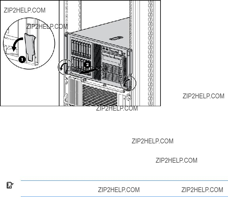
Extend the server from the rack
IMPORTANT: If the server is installed in a telco rack, remove the server from the rack to access internal components.
1.Extend the server on the rack rails until the server
WARNING: To reduce the risk of personal injury or equipment damage, be sure that the rack is adequately stabilized before extending a component from the rack.
WARNING: To reduce the risk of personal injury, be careful when pressing the server rail- release latches and sliding the server into the rack. The sliding rails could pinch your fingers.
Removal and replacement procedures 30
2.After performing the installation or maintenance procedure, slide the server into the rack by pressing the server
Power down the server
WARNING: To reduce the risk of personal injury, electric shock, or damage to the equipment, remove the power cord to remove power from the server. The front panel Power On/Standby button does not completely shut off system power. Portions of the power supply and some internal circuitry remain active until AC power is removed.
IMPORTANT: If installing a
1.Shut down the OS as directed by the OS documentation.
2.Press the Power On/Standby button to place the server in standby mode. When the server enters standby power mode, the system power LED changes to amber.
3.Disconnect the power cords.
The system is now without power.
Remove the server from the rack
To remove the server from an HP, telco, or
1.Power down the server (on page 31).
2.Disconnect the cabling.
Removal and replacement procedures 31
3.Extend the server from the rack. Reverse the server installation steps in the documentation that ships with the
4.Press the server
5.Place the server on a sturdy, level surface.
Front bezel
Tower servers have a removable front bezel that must be unlocked and opened before accessing the hard drive cage, and before removing the access panel.
To remove the component:
1.Open the front bezel (tower servers only).
IMPORTANT: You must unlock the front bezel before removing the access panel.
Removal and replacement procedures 32
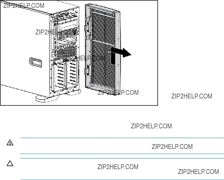
2.Lift up the front bezel and remove it from the chassis.
To replace the component, reverse the removal procedure.
Access panel
WARNING: To reduce the risk of personal injury from hot surfaces, allow the drives and the internal system components to cool before touching them.
CAUTION: Do not operate the server for long periods with the access panel open or removed. Operating the server in this manner results in improper airflow and improper cooling that can lead to thermal damage.
To remove the component:
1.Power down the server (on page 31).
2.Extend or remove the server from the rack ("Extend the server from the rack" on page 30, "Remove the server from the rack" on page 31).
3.Open the front bezel ("Front bezel" on page 32).
4.Using a
5.Lift up on the hood latch handle and remove the access panel.
To replace the component, reverse the removal procedure.
Rack bezel
To remove the component:
1.Extend or remove the server from the rack ("Extend the server from the rack" on page 30, "Remove the server from the rack" on page 31).
2.Remove the access panel ("Access panel" on page 33).
Removal and replacement procedures 33

3.Loosen the two thumbscrews that secure the rack bezel to the chassis.
4.Remove the rack bezel.
To replace the component, reverse the removal procedure.
Feet
NOTE: This procedure applies to tower servers only.
To remove the component:
1.Power down the server (on page 31).
2.Place the server on its side.
Removal and replacement procedures 34

3.Remove the feet.
To replace the component, slide it back into the locking slot. Be sure that the foot clicks securely into the chassis. Repeat with the remaining feet, as necessary.
Tower configuration panels
To remove the component:
1.Power down the server (on page 31).
2.Remove the tower feet ("Feet" on page 34).
3.Remove the tower configuration panels:
a.Use the
b.Remove the tower configuration panels.
To replace the component, reverse the removal procedure.
Removal and replacement procedures 35
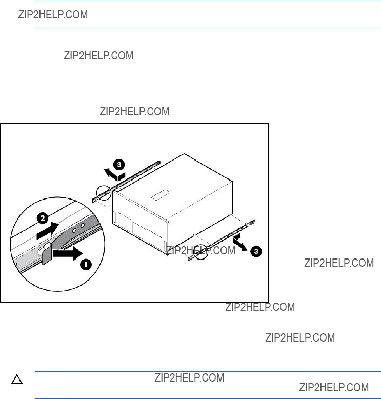
Rack rails
NOTE: This procedure applies to rack servers only.
To remove the component:
1.Power down the server (on page 31).
2.Remove the server from the rack (on page 31).
3.Pull the rack rail latch.
4.Slide the rail to the front of the server to release the rail.
5.Remove the rail.
6.Repeat the steps to remove the other rail.
To replace the component, reverse the removal procedure.
Power supply blank
CAUTION: Do not attempt to remove and replace a power supply as a
Removal and replacement procedures 36
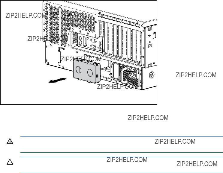
Remove the component as indicated.
To replace the component, reverse the removal procedure.
WARNING: To reduce the risk of electric shock, do not disassemble the power supply or attempt to repair it. Replace it only with the specified spare part.
CAUTION: Do not attempt to remove and replace a power supply as a
To remove the component:
1.Disconnect the power cord from the AC source.
2.Remove the power cord.
Removal and replacement procedures 37
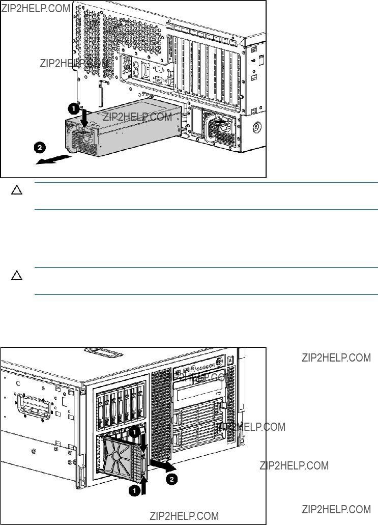
3.Remove the power supply.
CAUTION: To prevent improper cooling and thermal damage, do not operate the server unless all bays are populated with either a component or a blank.
To replace the component, reverse the removal procedure.
Hard drive blank
CAUTION: To prevent improper cooling and thermal damage, do not operate the server unless all bays are populated with either a component or a blank.
To remove the component:
1.Unlock and open the front bezel ("Front bezel" on page 32) (tower servers only).
2.Remove the blank.
Removal and replacement procedures 38
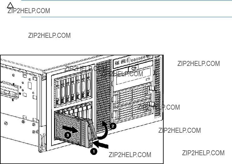
To replace the component, reverse the removal procedure.
Hard drive
To remove the component:
CAUTION: To prevent improper cooling and thermal damage, do not operate the server unless all bays are populated with either a component or a blank.
1.Determine the status of the hard drive from the
2.Back up all server data on the hard drive.
3.Remove the hard drive.
To replace the component, reverse the removal procedure.
Hard drive cage and backplane
To remove the component:
1.Power down the server (on page 31).
2.Do one of the following:
o Open or remove the tower bezel, as needed ("Front bezel" on page 32). o Extend the server from the rack (on page 30).
3.Remove the access panel ("Access panel" on page 33).
4.Remove the rack bezel (rack servers only) ("Rack bezel" on page 33).
5.Remove all hard drives ("Hard drive" on page 39) and hard drive blanks ("Hard drive blank" on page 38).
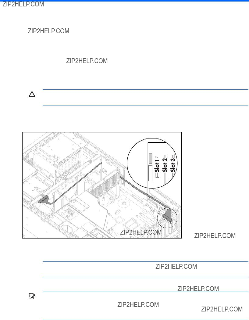
6.Disconnect the
Removal and replacement procedures 39

NOTE: The center wall is removed for illustration purposes only.
7.Disconnect the
IMPORTANT: When installing a x3/x1 SAS cable, HP recommends that the x3 part of the x3/x1 cable be linked to the SAS hard drive backplane connector that corresponds to hard drive slots 1 to 4. In this setup, hard drive slot 1 will not be available, but since hard drive slots 2 to 4 will be connected, one continuous volume can be created.
8.Remove the four screws that secure the drive cage to the chassis.
Removal and replacement procedures 40
9.Remove the SAS cage.
To replace the component, reverse the removal procedure.
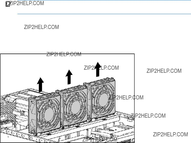
System fans
The server supports redundant
For the redundant configuration, fans 4, 5, and 6 are added to back up the primary fans. This configuration enables the server to continue operation in
???If one fan fails in
???If one fan fails in redundant mode, the server converts to
???If two fans fail in redundant mode, the server shuts down.
For more information, see "Fan locations (on page 90)."
All fans are identical. This procedure can be used for any of the six fan positions.
The server supports variable fan speeds. The fans operate at minimum speed until a temperature change requires a fan speed increase to cool the server.
The server shuts down in the following
???At POST:
o The BIOS suspends the server for 5 minutes if it detects a cautionary temperature level. If the cautionary temperature level is still detected after 5 minutes, the BIOS performs an orderly shutdown and enters Standby mode.
o The BIOS performs an orderly shutdown if two or more fans have failed.
o The server performs an immediate shutdown if it detects a critical temperature level.
IMPORTANT: An immediate shutdown is a
Removal and replacement procedures 41
???In the operating system:
o The Health Driver performs an orderly shutdown if it detects a cautionary temperature level. If the server detects a critical temperature level before the orderly shutdown occurs, the server performs an immediate shutdown. Additionally, the Health Driver performs an orderly shutdown if more than one fan is failed or removed.
o When Thermal Shutdown is disabled in RBSU, the server performs an immediate shutdown if it detects a critical temperature level.
IMPORTANT: An immediate shutdown is a
To remove the component:
1.Extend the server from the rack (on page 30).
2.Remove the access panel ("Access panel" on page 33).
3.Remove the fan.
To replace the component, reverse the removal procedure.
Expansion slot cover
To remove the component:
1.Power down the server (on page 31).
2.Extend the server from the rack, if applicable ("Extend the server from the rack" on page 30).
3.Remove the access panel ("Access panel" on page 33).
4.Press the slot release lever and swing the slot release lever upward.
Removal and replacement procedures 42
5.Remove the expansion slot cover.
Retain the slot cover for future use.
CAUTION: To prevent improper cooling and thermal damage, do not operate the server unless all PCI slots have either an expansion slot cover or an expansion board installed.
To replace the component, reverse the removal procedure.
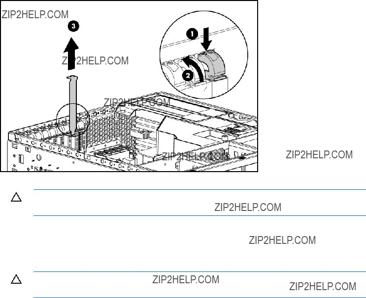
Expansion board
CAUTION: To prevent damage to the server or expansion boards, power down the server and remove all AC power cords before removing or installing the expansion boards.
To remove the component:
1.Power down the server (on page 31).
2.Extend the server from the rack, if applicable ("Extend the server from the rack" on page 30).
3.Remove the access panel ("Access panel" on page 33).
4.Disconnect any cables attached to the expansion board.
Removal and replacement procedures 43
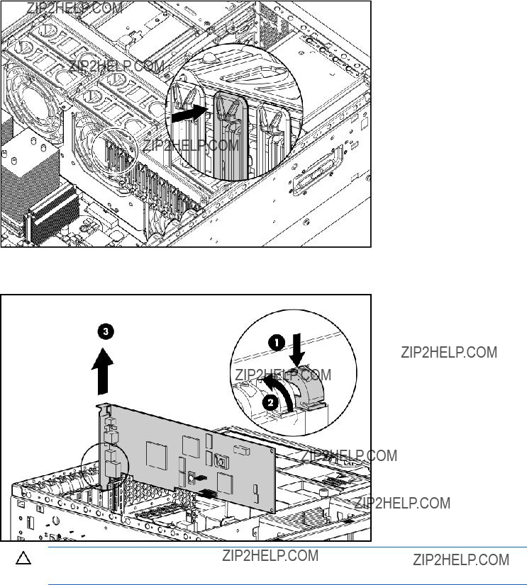
5.Release the retainer clip.
6.Press the slot release lever and swing the slot release lever upward.
7.Remove the expansion board.
CAUTION: Make a note of board locations. Be sure to install replacements in the same slots.
To replace the component, reverse the removal procedure.
Slot release lever
To remove the component:
1.Power down the server (on page 31).
2.Extend the server from the rack, if applicable ("Extend the server from the rack" on page 30).
3.Remove the access panel ("Access panel" on page 33).
Removal and replacement procedures 44
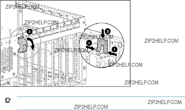
4.Remove the expansion slot cover ("Expansion slot cover" on page 42).
5.Remove any expansion board installed in the slot ("Expansion board" on page 43).
6.From the rear of the chassis, push up on the lever locking tab.
7.Pull the release lever forward to disengage the rear tabs from the chassis wall.
8.Remove the slot release lever.
To replace the component, reverse the removal procedure.
IMPORTANT: Be sure that the lever locking tab is locked into place. If the lever is not locked, it will not retain the expansion boards properly.
Processor air baffle
To remove the component:
1.Power down the server (on page 31).
2.Extend or remove the server from the rack ("Extend the server from the rack" on page 30, "Remove the server from the rack" on page 31).
3.Remove the access panel ("Access panel" on page 33).
Removal and replacement procedures 45
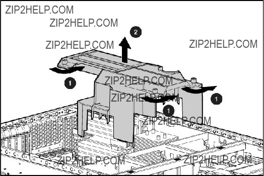
4.Remove the processor air baffle.
To replace the component, reverse the removal procedure.
Center wall
To remove the component:
1.Power down the server (on page 31).
2.Extend or remove the server from the rack ("Extend the server from the rack" on page 30, "Remove the server from the rack" on page 31).
3.Remove the access panel. ("Access panel" on page 33)
4.Remove the processor air baffle ("Processor air baffle" on page 45).
5.Remove the
6.Lift the center wall retaining latch.
Removal and replacement procedures 46

7.Remove the center wall.
To replace the component, reverse the removal procedure.
Media blanks
To remove the component:
1.Power down the server (on page 31).
2.Open or remove the tower bezel ("Front bezel" on page 32).
CAUTION: To prevent improper cooling and thermal damage, do not operate the server unless all bays are populated with either a component or a blank.
3.Remove the media blanks.
Removal and replacement procedures 47
NOTE: HP recommends that you remove all media blanks to facilitate drive installation.
Retain the blanks for future use.
To replace the component, reverse the removal procedure.
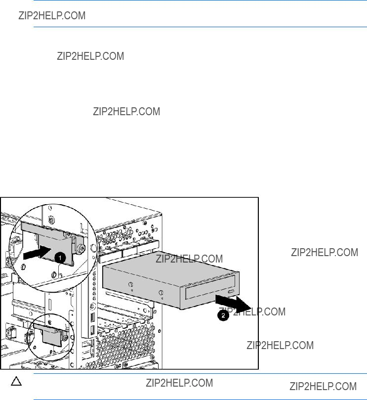
To remove the component:
1.Power down the server (on page 31).
2.Do one of the following:
o Unlock and remove the bezel ("Front bezel" on page 32). o Extend the server from the rack (on page 30).
3.Remove the access panel ("Access panel" on page 33).
4.Slide the media latch to release the drive and extend the drive from the bay to access the cabling.
CAUTION: To prevent improper cooling and thermal damage, do not operate the server unless all bays are populated with either a component or a blank.
5.Disconnect the data and power cables from the device.
6.Remove the
To replace the component, reverse the removal procedure.
Systems Insight Display
To remove the component:
1.Power down the server (on page 31).
2.Do one of the following:
Removal and replacement procedures 48
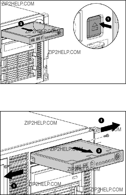
o Unlock and remove the bezel ("Front bezel" on page 32).
o Extend the server from the rack (on page 30).
3.Remove the access panel ("Access panel" on page 33).
4.Press the HP Systems Insight Display ejector button to extend the HP Systems Insight Display.
5.Disconnect the Systems Insight Display cable from the system board ("System board components" on page 84).
6.Remove two
7.Remove the Systems Insight Display.
To replace the component, reverse the removal procedure.
Memory boards and FBDIMMs
The server utilizes two memory boards. Each memory board consists of eight slots, numbered sequentially. The paired banks are identified by the letters A through D. Each memory board supports 2x1 interleaving.
Removal and replacement procedures 49
For maximum performance, HP recommends that both memory boards be populated with the same total amount of memory to support 4x1 interleaving across both memory branches.
Observe the following warnings when performing a replacement procedure:
WARNING: Always comply with all electrostatic and thermal guidelines to prevent bodily injury and ensure a properly functioning system when performing
WARNING: To prevent personal injury from hazardous energy:
???Remove watches, rings, or other metal objects.
???Use tools with insulated handles.
???Do not place tools or metal parts on top of batteries.
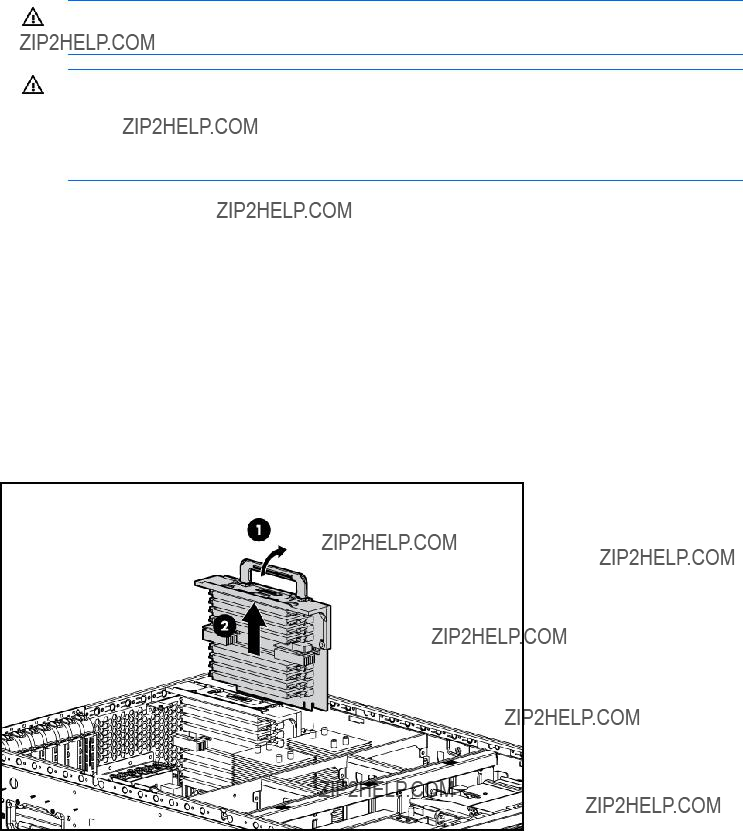
Memory board
To remove the component:
1.Power down the server (on page 31).
2.Do one of the following:
o Open or remove the tower bezel, as needed ("Front bezel" on page 32). o Extend the server from the rack (on page 30).
3.Remove the access panel ("Access panel" on page 33).
4.Remove the processor air baffle ("Processor air baffle" on page 45).
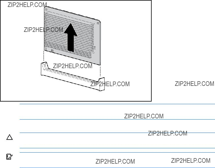
5.Remove the memory board and place it on a flat surface.
To replace the component, reverse the removal procedure.
FBDIMM
To remove the component:
1.Power down the server (on page 31).
Removal and replacement procedures 50
2.Do one of the following:
o Open or remove the tower bezel, as needed ("Front bezel" on page 32). o Extend the server from the rack (on page 30).
3.Remove the access panel ("Access panel" on page 33).
4.Remove the processor air baffle ("Processor air baffle" on page 45).
5.Remove a memory board ("Memory board" on page 50).
6.Remove the FBDIMM.
To replace the component, reverse the removal procedure.
Processor
CAUTION: To prevent possible server malfunction, do not mix processors of different speeds or cache sizes. Refer to the label on the processor heatsink for a description of the processor.
CAUTION: Be sure that you have the current version of the system ROM. Failure to flash the ROM with the correct version before installing or replacing the processor causes system failure. For the most current version of the ROM, go to the HP website (http://www.hp.com/support).
CAUTION: To avoid damage to the system board:
???Do not touch the processor socket contacts.
???Always install the processor socket cover after removing the processor from the socket.
???Do not tilt or slide the processor when lowering the processor into the socket.
CAUTION: To avoid damage to the processor:
???Handle the processor only by the edges.
???Do not touch the bottom of the processor, especially the contact area.
Removal and replacement procedures 51

IMPORTANT: Processor socket 1 must always be populated. If processor socket 1 is empty, the server does not power up.
To remove the component:
1.Power down the server (on page 31).
2.Do one of the following:
o Unlock and remove the bezel ("Front bezel" on page 32). o Extend the server from the rack (on page 30).
3.Remove the access panel ("Access panel" on page 33).
4.Remove the processor air baffle ("Processor air baffle" on page 45).
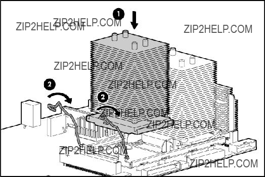
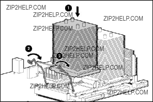
5.Open the heatsink retaining latches.
6.Remove the heatsink.
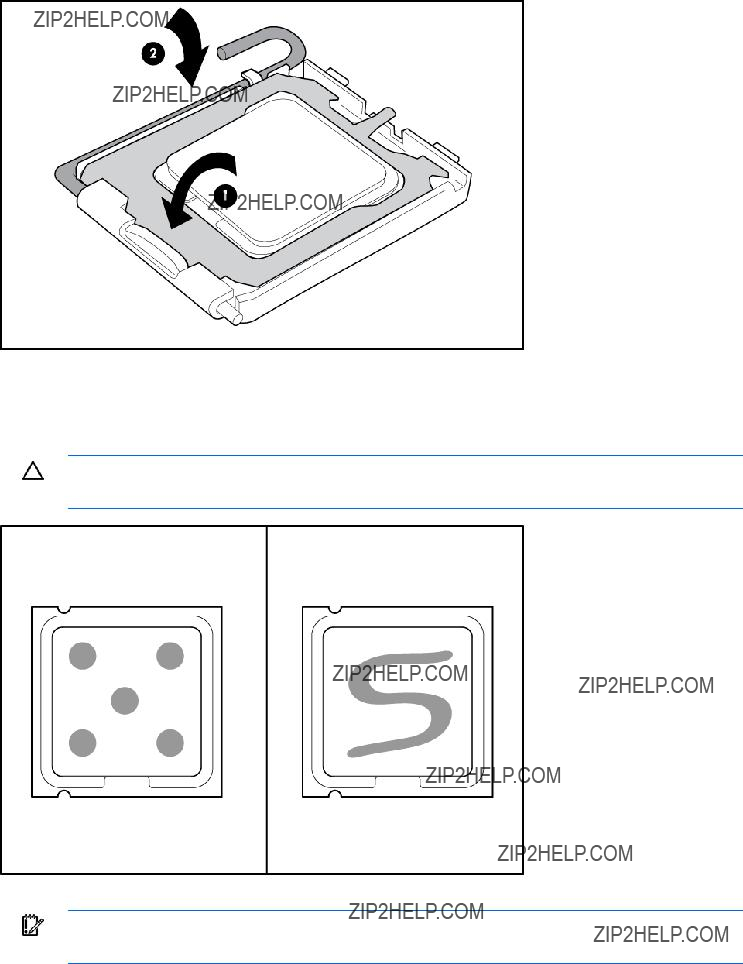
7.Open the processor retaining latch and the processor socket retaining bracket.
Removal and replacement procedures 52
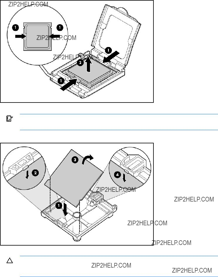
8.Using your fingers, remove the failed processor.
To replace the component:
IMPORTANT: Be sure the processor remains inside the processor installation tool.
1.If the processor has separated from the installation tool, carefully
2.Align the processor installation tool with the socket and install the spare processor.
CAUTION: The processor is designed to fit one way into the socket. Use the alignment guides on the processor and socket to properly align the processor with the socket. Refer to the server hood label for specific instructions.
Removal and replacement procedures 53
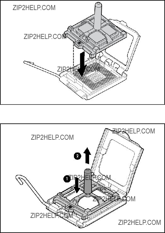
3.Press down firmly until the processor installation tool clicks and separates from the processor, and then remove the processor installation tool.
Removal and replacement procedures 54
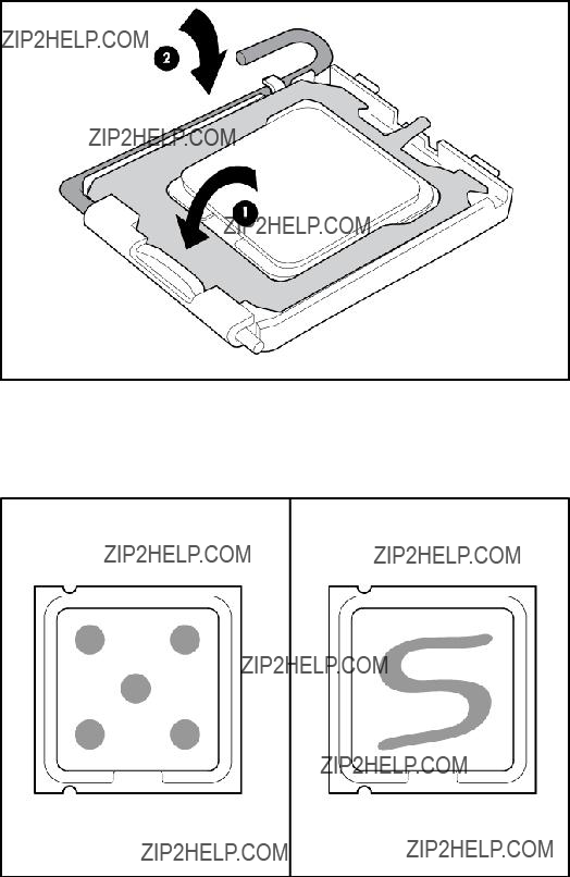
4.Close the processor retaining latch and the processor socket retaining bracket.
5.Clean the old thermal grease from the heatsink with the alcohol swab. Allow the alcohol to evaporate before continuing.
6.Apply all the grease to the top of the processor in one of the following patterns to ensure even distribution:
7.Install the heatsink.
Removal and replacement procedures 55
8.Close the heatsink retaining latches.
9.Install the processor air baffle.
10.Install the access panel.
11.Do one of the following:
o Install and lock the bezel.
o Slide the server back into the rack.
12.Power up the server.
Heatsink
To remove the component:
1.Power down the server (on page 31).
2.Do one of the following:
o Unlock and remove the bezel ("Front bezel" on page 32). o Extend the server from the rack (on page 30).
3.Remove the access panel ("Access panel" on page 33).
4.Remove the processor air baffle ("Processor air baffle" on page 45).
5.Open the heatsink retaining latches.
Removal and replacement procedures 56
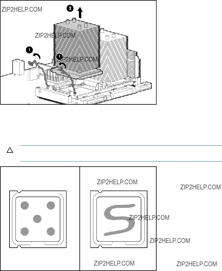
6.Remove the heatsink.
To replace the heatsink:
1.Use the alcohol swab to remove all the existing thermal grease from the processor. Allow the alcohol to evaporate before continuing.
2.Apply all the grease to the top of the processor in one of the following patterns to ensure even distribution.
CAUTION: The heatsink thermal interface media is not reusable and must be replaced if the heatsink is removed from the processor after it has been installed.
3.Install the heatsink.
Removal and replacement procedures 57
4.Close the heatsink retaining latches.
5.Install the processor air baffle.
6.Install the access panel.
7.Do one of the following:
o Install and lock the bezel.
o Slide the server back into the rack.
8.Power up the server.
PPM
To remove the component:
1.Power down the server (on page 31).
2.Do one of the following:
o Unlock and remove the bezel ("Front bezel" on page 32). o Extend the server from the rack (on page 30).
3.Remove the access panel ("Access panel" on page 33).
4.Remove the processor air baffle ("Processor air baffle" on page 45).
Removal and replacement procedures 58
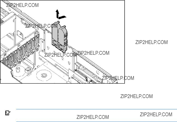
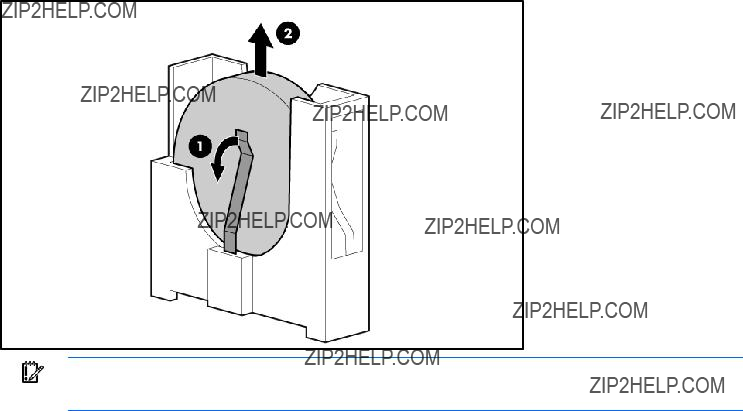
5.Remove the PPM.
NOTE: The appearance of compatible PPMs may vary.
To replace the component, reverse the removal procedure.
CAUTION: Only install a PPM if the processor is installed. Both the PPM and the processor must be installed together, otherwise the system does not boot.
IMPORTANT: PPMs do not seat if turned the wrong way.
Power supply backplane
To remove the component:
1.Power down the server (on page 31).
2.Remove all
3.Do one of the following:
o Unlock and remove the bezel ("Front bezel" on page 32). o Extend the server from the rack (on page 30).
4.Remove the access panel ("Access panel" on page 33).
5.Remove all expansion boards ("Expansion board" on page 43).
6.Remove the processor air baffle ("Processor air baffle" on page 45).
7.Remove the center wall ("Center wall" on page 46).
Removal and replacement procedures 59
8.Disconnect the signal cable from the power supply backplane.
9.Disconnect all cables from the system board, as necessary, to access the power supply backplane.
10.Remove the power supply backplane.
To replace the component, reverse the removal procedure.
IMPORTANT: Be sure to align the two retaining guides on the chassis with the holes on the power supply backplane when replacing it.
Video connector
To remove the component:
1.Power down the server (on page 31).
2.Do one of the following:
o Unlock and remove the bezel ("Front bezel" on page 32).
Removal and replacement procedures 60
o Extend the server from the rack (on page 30).
3.Remove the access panel ("Access panel" on page 33).
4.Remove all expansion boards ("Expansion board" on page 43).
5.Remove the processor air baffle ("Processor air baffle" on page 45).
6.Remove the center wall ("Center wall" on page 46).
7.Remove the memory board ("Memory board" on page 50).
8.Disconnect the cable from the internal video connector on the system board.
9.Extend or remove the media bay spacer from the chassis.
10.Remove the video connector.
11.Remove the cable from the clip on the media bay spacer.
To replace the component, reverse the removal procedure.
Removal and replacement procedures 61
BBWC battery pack
CAUTION: To prevent a server malfunction or damage to the equipment, do not add or remove the battery pack while an array capacity expansion, RAID level migration, or stripe size migration is in progress.
CAUTION: After the server is powered down, wait 15 seconds and then check the amber LED before unplugging the cable from the cache module. If the amber LED blinks after 15 seconds, do not remove the cable from the cache module. The cache module is backing up data, and data is lost if the cable is detached.
To remove the component:
1.Power down the server (on page 31).
2.Do one of the following:
o Unlock and remove the bezel ("Front bezel" on page 32). o Extend the server from the rack (on page 30).
3.Remove the access panel ("Access panel" on page 33).
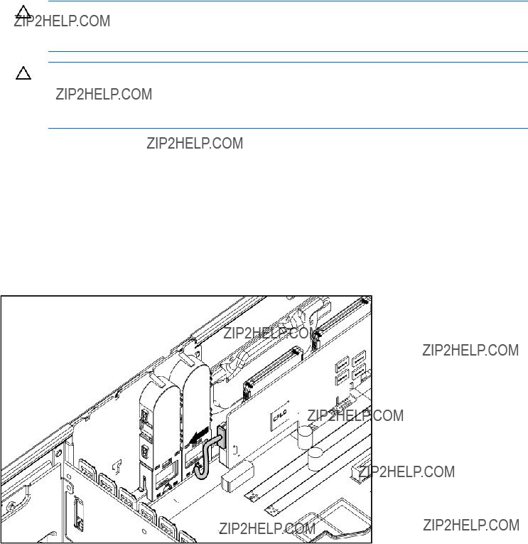
4.Disconnect the cable from the cache module only if the battery pack is not being used to recover data from the server or transfer data to another server.
Removal and replacement procedures 62
5.Remove the battery pack.
To replace the component, reverse the removal procedure.
System board
IMPORTANT: If replacing the system board or clearing NVRAM, you must
To remove the component:
1.Power down the server (on page 31).
2.Do one of the following:
o Unlock and remove the bezel ("Front bezel" on page 32). o Extend the server from the rack (on page 30).
3.Remove the access panel ("Access panel" on page 33).
4.Remove all expansion boards ("Expansion board" on page 43).
5.Remove the processor air baffle ("Processor air baffle" on page 45).
6.Remove the center wall ("Center wall" on page 46).
7.Remove the memory board ("Memory board" on page 50).
8.Remove the PPM ("PPM" on page 58).
9.Disconnect all cables attached to the system board.
10.Remove the heatsink ("Heatsink" on page 56).
Removal and replacement procedures 63
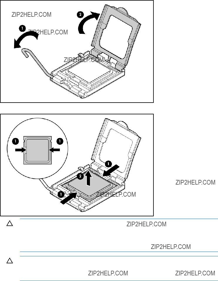
11. Open the processor retaining latch and the processor socket retaining bracket.
12. Using your fingers, remove the processor from the failed system board.
CAUTION: To avoid damage to the system board:
???Do not touch the processor socket contacts.
???Always install the processor socket cover after removing the processor from the socket.
???Do not tilt or slide the processor when lowering the processor into the socket.
CAUTION: To avoid damage to the processor:
???Handle the processor only by the edges.
???Do not touch the bottom of the processor, especially the contact area.
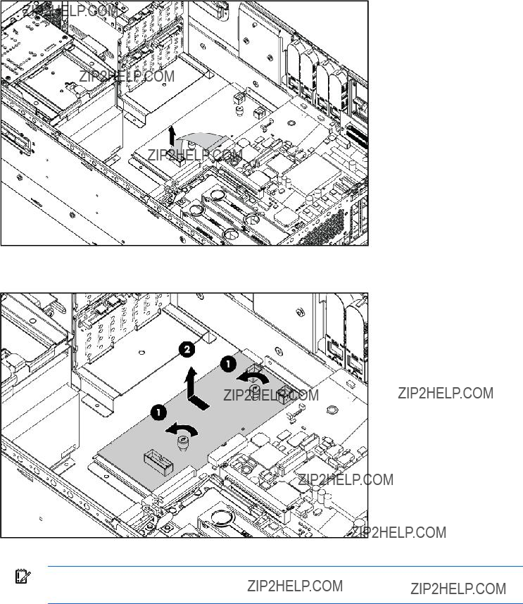
13.Loosen the two thumbscrews securing the system board to the chassis.
14.Slide the system board toward the front of the chassis to release it from the two retaining guides.
Removal and replacement procedures 64
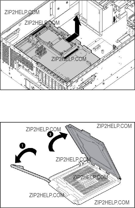
15. Lift the system board out of the chassis and tilt it to one side to clear the cable guide.
To replace the system board:
1.Install the spare system board in the server before installing the processor.
2.Prepare the processor socket on the spare system board:
a. Open the processor retaining latch and the processor socket retaining bracket.
Removal and replacement procedures 65
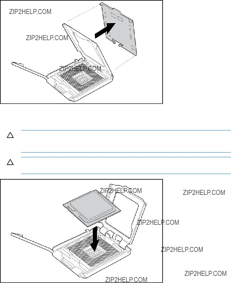
b. Remove the processor socket protective cover.
3.Install the processor socket cover onto the processor socket of the failed system board. The cover protects the socket during shipping when the failed board is returned.
4.Install the processor onto the spare system board.
CAUTION: The processor is designed to fit one way into the socket. Use the alignment guides on the processor and socket to properly align the processor with the socket. Refer to the server hood label for specific instructions.
CAUTION: Always install the processor parallel to the system board to avoid damage to the pins.
Removal and replacement procedures 66
5.Close the processor retaining latch and the processor socket retaining bracket.
6.Clean the old thermal grease from the heatsink and the top of the processor with the alcohol swab. Allow the alcohol to evaporate before continuing.
7.Apply all the grease to the top of the processor in one of the following patterns to ensure even distribution.
CAUTION: The heatsink thermal interface media is not reusable and must be replaced if the heatsink is removed from the processor after it has been installed.
8.Install the heatsink ("Heatsink" on page 56).
IMPORTANT: To ensure proper cooling, be sure the processor air baffle is installed at all times (if applicable).
9.Install all other components removed.
10.Power up the server.
Removal and replacement procedures 67

After you replace the system board, you must
1.During the server startup sequence, press the F9 key to access RBSU.
2.Select the System Options menu.
3.Select Serial Number. The following warning is displayed:
WARNING! WARNING! WARNING! The serial number is loaded into the system during the manufacturing process and should NOT be modified. This option should only be used by qualified service personnel. This value should always match the serial number sticker located on the chassis.
4.Press the Enter key to clear the warning.
5.Enter the serial number and press the Enter key.
6.Select Product ID.
7.Enter the product ID and press the Enter key.
8.Press the Esc key to close the menu.
9.Press the Esc key to exit RBSU.
Press the F10 key to confirm exiting RBSU. The server will automatically reboot.
Battery
If the server no longer automatically displays the correct date and time, you may need to replace the battery that provides power to the
WARNING: The computer contains an internal lithium manganese dioxide, a vanadium pentoxide, or an alkaline battery pack. A risk of fire and burns exists if the battery pack is not properly handled. To reduce the risk of personal injury:
???Do not attempt to recharge the battery.
???Do not expose the battery to temperatures higher than 60??C (140??F).
???Do not disassemble, crush, puncture, short external contacts, or dispose of in fire or water.
???Replace only with the spare designated for this product.
To remove the component:
1.Power down the server (on page 31).
2.Do one of the following:
o Open or remove the tower bezel, as needed ("Front bezel" on page 32). o Extend the server from the rack (on page 30).
3.Remove the access panel ("Access panel" on page 33).
4.Remove the processor air baffle ("Processor air baffle" on page 45).
Removal and replacement procedures 68
5.Remove the battery.
IMPORTANT: Replacing the system board battery resets the system ROM to its default configuration. After replacing the battery, reconfigure the system through RBSU.
To replace the component, reverse the removal procedure.
For more information about battery replacement or proper disposal, contact an authorized reseller or an authorized service provider.
Removal and replacement procedures 69
Cabling
Cabling overview
This section provides guidelines that help you make informed decisions about cabling the server and hardware options to optimize performance.
For information on cabling peripheral components, refer to the white paper on
CAUTION: When routing cables, always be sure that the cables are not in a position where they can be pinched or crimped.
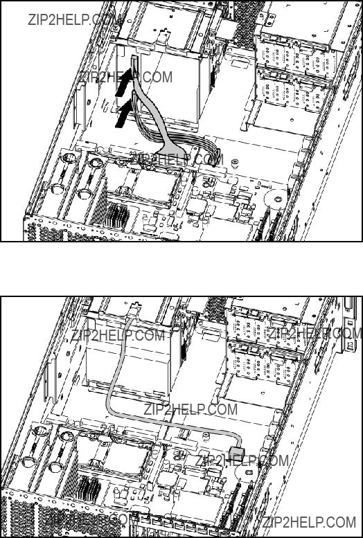
Diskette drive cabling
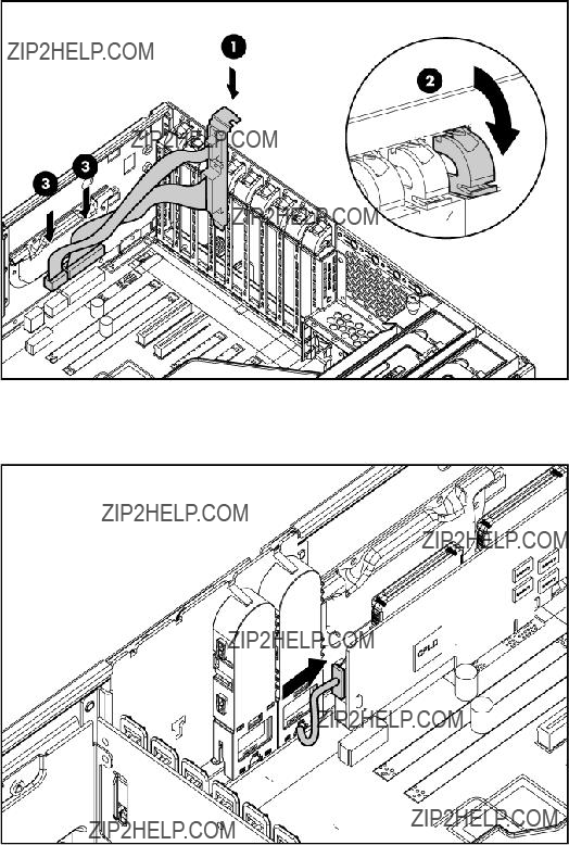
SAS cabling
NOTE: The center wall is removed for illustration purposes only.
???SAS data cabling
IMPORTANT: When installing a x3/x1 SAS cable, HP recommends that the x3 part of the x3/x1 cable be linked to the SAS hard drive backplane connector that corresponds to hard drive slots 1 to 4. In this setup, hard drive slot 1 will not be available, but since hard drive slots 2 to 4 will be connected, one continuous volume can be created.
Cabling 70
???SAS power cabling
Cabling 71
Video cabling
Cabling 72
Parallel/serial port cabling
BBWC option cabling
Cabling 73

Internal USB connector
Storage device cabling guidelines
CAUTION: To prevent damage to the equipment, be sure that the server is powered down, all cables are disconnected from the back of the server, and the power cord is disconnected from the grounded (earthed) AC outlet before installing devices.
CAUTION: To prevent damage to electrical components, properly ground the server before beginning any installation procedure. Improper grounding can cause electrostatic discharge.
HP Systems Insight Display cabling
Cabling 74
Diagnostic tools
Troubleshooting resources
The HP ProLiant Servers Troubleshooting Guide provides procedures for resolving common problems and comprehensive courses of action for fault isolation and identification, error message interpretation, issue resolution, and software maintenance on ProLiant servers and server blades. This guide includes problem- specific flowcharts to help you navigate complex troubleshooting processes. To view the guide, select a language:
???English (http://www.hp.com/support/ProLiant_TSG_en)
???French (http://www.hp.com/support/ProLiant_TSG_fr)
???Italian (http://www.hp.com/support/ProLiant_TSG_it)
???Spanish (http://www.hp.com/support/ProLiant_TSG_sp)
???German (http://www.hp.com/support/ProLiant_TSG_gr)
???Dutch (http://www.hp.com/support/ProLiant_TSG_nl)
???Japanese (http://www.hp.com/support/ProLiant_TSG_jp)
Automatic Server Recovery
ASR is a feature that causes the system to restart when a catastrophic operating system error occurs, such as a blue screen, ABEND, or panic. A system
ASR increases server availability by restarting the server within a specified time after a system hang or shutdown. At the same time, the HP SIM console notifies you by sending a message to a designated pager number that ASR has restarted the system. You can disable ASR from the HP SIM console or through RBSU.
HP Systems Insight Manager
HP SIM is a
IMPORTANT: You must install and use HP SIM to benefit from the
For additional information, refer to the Management CD in the HP ProLiant Essentials Foundation Pack or the HP SIM website (http://www.hp.com/go/hpsim).
Diagnostic tools 75

Integrated Management Log
The IML records hundreds of events and stores them in an
You can view recorded events in the IML in several ways, including the following:
???From within HP SIM ("HP Systems Insight Manager" on page 75)
???From within Survey Utility
???From within operating
o For Windows??: IML Viewer
o For Linux: IML Viewer Application
???From within the iLO 2 user interface
???From within HP Insight Diagnostics (on page 79)
For more information, refer to the Management CD in the HP ProLiant Essentials Foundation Pack.
HP Integrated Lights Out 2 technology
The iLO 2 subsystem is a standard component of selected ProLiant servers that provides server health and remote server manageability. The iLO 2 subsystem includes an intelligent microprocessor, secure memory, and a dedicated network interface. This design makes iLO 2 independent of the host server and its operating system. The iLO 2 subsystem provides remote access to any authorized network client, sends alerts, and provides other server management functions.
Using iLO 2, you can:
???Remotely power up, power down, or reboot the host server.
???Send alerts from iLO 2 regardless of the state of the host server.
???Access advanced troubleshooting features through the iLO 2 interface.
???Diagnose iLO 2 using HP SIM through a web browser and SNMP alerting.
For more information about iLO 2 features, refer to the iLO 2 documentation on the Documentation CD or on the HP website
Option ROM Configuration for Arrays
NOTE: ORCA is supported with the use of an optional HP Array Controller.
Before installing an operating system, you can use the ORCA utility to create the first logical drive, assign RAID levels, and establish online spare configurations.
The utility provides support for the following functions:
???Configuring one or more logical drives using physical drives on one or more SCSI buses
???Viewing the current logical drive configuration
Diagnostic tools 76
???Deleting a logical drive configuration
If you do not use the utility, ORCA will default to the standard configuration.
For more information regarding array controller configuration, refer to the controller user guide.
For more information regarding the default configurations that ORCA uses, refer to the HP
ProLiant Essentials Rapid Deployment Pack
The RDP is an integrated HP and Altiris solution that automates the process of deploying and provisioning server software. Refer to the RDP website (http://www.hp.com/servers/rdp).
HP
RBSU is a configuration utility embedded in ProLiant servers that performs a wide range of configuration activities that can include the following:
???Configuring system devices and installed options
???Enabling and disabling system features
???Displaying system information
???Selecting the primary boot controller
???Configuring memory options
???Language selection
For more information on RBSU, see the HP
ROMPaq utility
The ROMPaq utility enables you to upgrade the system firmware (BIOS) or
The ROMPaq utility checks the system and provides a choice (if more than one exists) of available firmware revisions.
For more information about the ROMPaq utility, see the HP website (http://www.hp.com/go/support).
System Online ROM flash component utility
The Online ROM Flash Component Utility enables system administrators to efficiently upgrade system or controller ROM images across a wide range of servers and array controllers. This tool has the following features:
???Works offline and online
???Supports Microsoft?? Windows NT??, Windows?? 2000, Windows Server?? 2003, Novell Netware, and Linux operating systems
Diagnostic tools 77

IMPORTANT: This utility supports operating systems that may not be supported by the server. For operating systems supported by the server, see the HP website (http://www.hp.com/support).
???Integrates with other software maintenance, deployment, and operating system tools
???Automatically checks for hardware, firmware, and operating system dependencies, and installs only the correct ROM upgrades required by each target server
To download the tool and for more information, see the HP website (http://www.hp.com/support).
SmartStart software
SmartStart is a collection of software that optimizes
SmartStart assists the deployment process by performing a wide range of configuration activities, including:
???Configuring hardware using embedded configuration utilities, such as RBSU and ORCA
???Preparing the system for installing
???Installing optimized server drivers, management agents, and utilities automatically with every assisted installation
???Testing server hardware using the Insight Diagnostics Utility ("HP Insight Diagnostics" on page 79)
???Installing software drivers directly from the CD. With systems that have internet connection, the SmartStart Autorun Menu provides access to a complete list of ProLiant system software.
???Enabling access to the Array Configuration Utility, Array Diagnostic Utility, and Erase Utility
SmartStart is included in the HP ProLiant Essentials Foundation Pack. For more information about SmartStart software, refer to the HP ProLiant Essentials Foundation Pack or the HP website (http://h18013.www1.hp.com/products/servers/management/smartstart/index.html).
SmartStart Scripting Toolkit
The SmartStart Scripting Toolkit is a server deployment product that delivers an unattended automated installation for
Using SmartStart technology, the Scripting Toolkit provides a flexible way to create standard server configuration scripts. These scripts are used to automate many of the manual steps in the server configuration process. This automated server configuration process cuts time from each server deployed, making it possible to scale server deployments to high volumes in a rapid manner.
For more information, and to download the SmartStart Scripting Toolkit, refer to the HP website (http://www.hp.com/servers/sstoolkit).
Diagnostic tools 78
HP Insight Diagnostics
HP Insight Diagnostics is a proactive server management tool, available in both offline and online versions, that provides diagnostics and troubleshooting capabilities to assist IT administrators who verify server installations, troubleshoot problems, and perform repair validation.
HP Insight Diagnostics Offline Edition performs various
HP Insight Diagnostics Online Edition is a
For more information or to download the utility, refer to the HP website (http://www.hp.com/servers/diags).
Diagnostic tools 79

Server component identification
Front panel components
???Rack model
Server component identification 80
???Tower model
Front panel LEDs and buttons
Server component identification 81

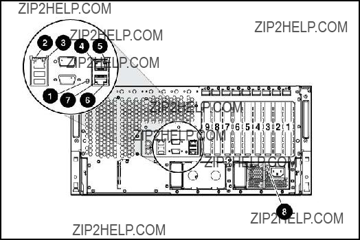
Rear panel components
Server component identification 82
Rear panel LEDs

System board components
Server component identification 84

System maintenance switch
When the system maintenance switch position 6 is set to the On position, the system is prepared to erase all system configuration settings from both CMOS and NVRAM.
CAUTION: Clearing CMOS and/or NVRAM deletes configuration information. Be sure to properly configure the server or data loss could occur.
Server component identification 85

Internal system health LED combinations
When the internal system health LED on the front panel ("Front panel LEDs and buttons" on page 81) illuminates either amber or red, the server is experiencing a health event. Combinations of illuminated HP Systems Insight Display LEDs and the internal health LED indicate system status.
NOTE: The system management driver must be installed for the internal system health LED to provide
The front panel health LEDs indicate only the current hardware status. In some situations, HP SIM may report server status differently than the health LEDs because the software tracks more system attributes.
Server component identification 86
SAS and SATA device numbers
The server supports a combination of up to 16 SAS and SATA hard drives in two hard drive cages. HP recommends populating hard drive bays starting with the lowest SAS or SATA device number.
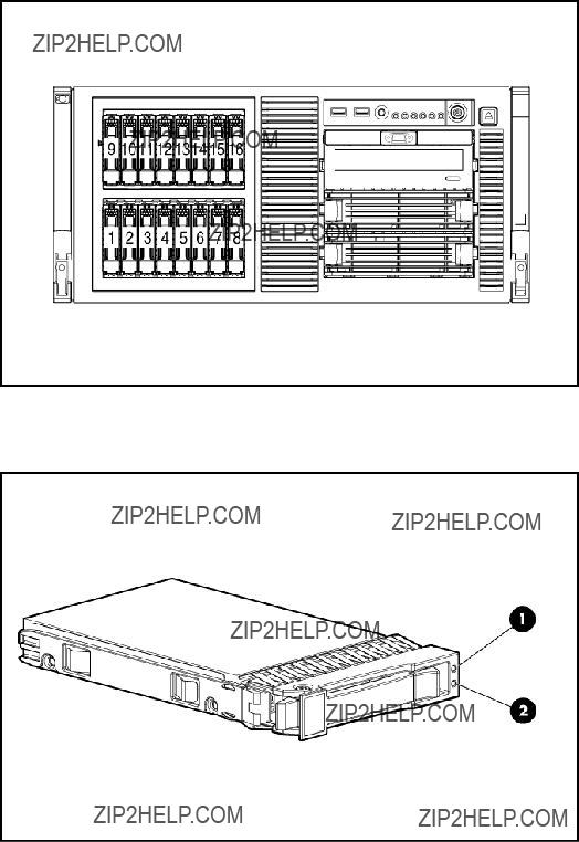
SAS and SATA hard drive LEDs
Server component identification 87

SAS and SATA hard drive LED combinations
Server component identification 88
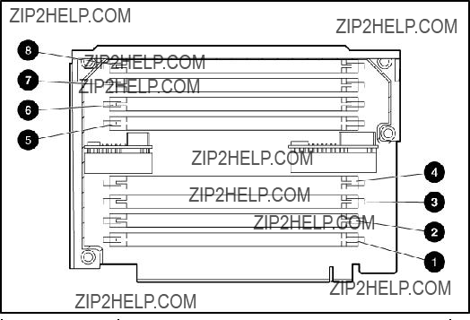
FBDIMM slots
The server supports two memory boards, each containing eight slots with paired banks identified by the letters A through D.
Server component identification 89

Power supply backplane LED
If the power supply backplane LED is illuminated, the power supply backplane has failed.
Fan locations
Server component identification 90
Systems Insight Display LEDs
To view a quick reference for component identification and status, access the Systems Insight Display.
Server component identification 91
* If all FBDIMM LEDs for a memory board are flashing, the memory board is unseated.
Server component identification 92

Specifications
Environmental specifications
*All temperature ratings shown are for sea level. An altitude derating of 1??C per 300 m (1.8??F per 1,000 ft) to 3048 m (10,000 ft) is applicable. No direct sunlight allowed.
**Storage maximum humidity of 95% is based on a maximum temperature of 45??C (113??F). Altitude maximum for storage corresponds to a pressure minimum of 70 KPa.
Server specifications
Specifications 93

* 100 to 127 VAC is required for 10 A; 200 to 240 VAC is required for 6.7 A.
For
FBDIMM specifications
CAUTION: Be sure to install FBDIMMs in the proper configuration. Refer to the Documentation CD.
*Use only Registered DDR2 FBDIMMs. Use HP FBDIMMs only.
Specifications 94

SAS and SATA hard drive specifications
Specifications 96

Acronyms and abbreviations
ABEND
abnormal end
ASR
Automatic Server Recovery
BBWC
BIOS
Basic Input/Output System
DDR
double data rate
DIMM
dual inline memory module
FBDIMM
fully buffered DIMM
IDE
integrated device electronics
iLO 2
Integrated
IML
Integrated Management Log
LED
NIC
network interface controller
Acronyms and abbreviations 97
NMI
NVRAM
ORCA
Option ROM Configuration for Arrays
PCI Express
Peripheral Component Interconnect Express
peripheral component interconnect extended
POST
PPM
processor power module
RAID
redundant array of inexpensive (or independent) disks
RBSU
RDP
Rapid Deployment Pack
ROM
SAS
serial attached SCSI
SATA
serial ATA
SCSI
small computer system interface
Acronyms and abbreviations 98
SIM
Systems Insight Manager
SNMP
Simple Network Management Protocol
UID
unit identification
USB
universal serial bus
Acronyms and abbreviations 99

Index
A
AC power supply 83 access panel 33
air baffle 30, 45
ASR (Automatic Server Recovery) 75 Automatic Server Recovery (ASR) 75 Autorun menu 78
B
battery 84
buttons 80
C
D
DC power supply 82, 83, 84 diagnostic tools 75, 77, 78, 79 diagnostics utility 79
diskette drive 70, 94 drive LEDs 88
E
LEDs, power supply 90
LEDs, Systems Insight Display 91
M
management tools 75 mechanical components 17 media drive 48
media drive blank 47 memory boards 50 memory slots 84, 89
N
network connector LEDs 83 NIC LEDs 81, 91
O
Online ROM Flash Component Utility 77
ORCA (Option ROM Configuration for Arrays) 76 overtemperature LED 91
P
power supply signal connector 84, 90, 91 powering down 31
PPM failure LEDs 91 PPM slots 84
preparation procedures 30 processor failure LEDs 90, 91 processors 84
R
rack bezel 33 rails, removing 36
RBSU
rear panel LEDs 83
remote management connector 84 removal and replacement procedures 28 requirements, power 94
S
safety considerations 28 SAS backplane 39
SAS cabling 70
SAS drive numbers 87, 88 SAS drives 87, 88
SAS hard drive 88 SATA hard drive 88
SATA hard drive LEDs 87, 88 scripted installation 78
slot release levers 44 SmartStart autorun menu 78 SmartStart Scripting Toolkit 78 SmartStart, overview 78 spare part numbers 17, 21 specifications 93 specifications, server 93, 94 static electricity 28
storage system, cabling 74 support packs 78
switches 85
symbols on equipment 28 system board components 84 system board LEDs 91 system components 21
system maintenance switch 84, 85
System Online ROM flash component utility 77 system power connector 84
system power LED 31, 81 Systems Insight Display 91 Systems Insight Manager 75
T
telco racks 30
temperature, overtemperature LED 91 tools 28, 75
Torx screwdriver 28 tower cover, removing 35
U
UID LED 81, 83
Index 101