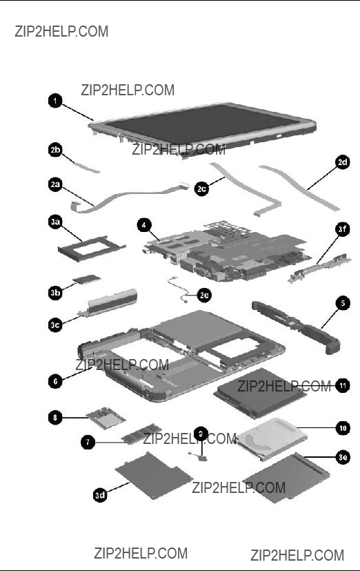
Maintenance and Service

Guide

HP Compaq Tablet PC TC1100

Document Part Number: 335572-002

June 2004

This guide is a troubleshooting reference used for maintaining and servicing the tablet PC. It provides comprehensive information on identifying tablet PC features, components, and spare parts, troubleshooting tablet PC problems, and performing tablet PC disassembly procedures.

?? Copyright 2004 Hewlett-Packard Development Company, L.P.

Microsoft and Windows are U.S. registered trademarks of Microsoft Corporation. Intel, Pentium, and Celeron are trademarks or registered trademarks of Intel Corporation or its subsidiaries in the United States and other countries. SD Logo is a trademark of its proprietor. Bluetooth is a trademark owned by its proprietor and used by Hewlett-Packard Company under license.

The information contained herein is subject to change without notice. The only warranties for HP products and services are set forth in the express warranty statements accompanying such products and services. Nothing herein should be construed as constituting an additional warranty. HP shall not be liable for technical or editorial errors or omissions contained herein.

Maintenance and Service Guide

HP Compaq Tablet PC TC1100

Second Edition June 2004

First Edition February 2004

Document Part Number: 335572-002

Contents

1 Product Description

1.1 Models. . . . . . . . . . . . . . . . . . . . . . . . . . . . . . . . . . . . 1???3

1.2 Features . . . . . . . . . . . . . . . . . . . . . . . . . . . . . . . . . . 1???32

1.3 Clearing a Password . . . . . . . . . . . . . . . . . . . . . . . . 1???34

1.4 Power Management. . . . . . . . . . . . . . . . . . . . . . . . . 1???35

1.5 Tablet PC External Components. . . . . . . . . . . . . . . 1???36

1.6 Keyboard Components . . . . . . . . . . . . . . . . . . . . . . 1???49

1.7 HP Tablet PC Docking Station Components . . . . . 1???54

1.8 Design Overview. . . . . . . . . . . . . . . . . . . . . . . . . . . 1???58

2 Troubleshooting

2.1 Setup and Diagnostics Utilities . . . . . . . . . . . . . . . . . 2???2 Selecting Setup or HP Diagnostics . . . . . . . . . . . . . . 2???2 Selecting from the File Menu . . . . . . . . . . . . . . . . . . 2???3 Selecting from the Security Menu. . . . . . . . . . . . . . . 2???4 Selecting from the Advanced Menu . . . . . . . . . . . . . 2???6

2.2 Using HP Diagnostics for Windows . . . . . . . . . . . . . 2???8 Obtaining, Saving or Printing

Configuration Information . . . . . . . . . . . . . . . . . . . . 2???8 Obtaining, Saving or Printing Diagnostic Test Information . . . . . . . . . . . . . . . . . . . . . . . . . . . . . . . . 2???9 Troubleshooting Flowcharts . . . . . . . . . . . . . . . . . . 2???11 Flowchart 2.1???Initial Troubleshooting . . . . . . . . . 2???12 Flowchart 2.2???No Power, Part 1 . . . . . . . . . . . . . . 2???13 Flowchart 2.3???No Power, Part 2 . . . . . . . . . . . . . . 2???14 Flowchart 2.4???No Power, Part 3 . . . . . . . . . . . . . . 2???15

Contents

Flowchart 2.5???No Power, Part 4 . . . . . . . . . . . . . . 2???16 Flowchart 2.6???No Video, Part 1 . . . . . . . . . . . . . . 2???17 Flowchart 2.7???No Video, Part 2 . . . . . . . . . . . . . . 2???18 Flowchart 2.8???Nonfunctioning Docking

Station (if applicable) . . . . . . . . . . . . . . . . . . . . . . . 2???19 Flowchart 2.9???No Operating System (OS)

Loading . . . . . . . . . . . . . . . . . . . . . . . . . . . . . . . . . . 2???20 Flowchart 2.10???No OS Loading from Hard

Drive, Part 1 . . . . . . . . . . . . . . . . . . . . . . . . . . . . . . 2???21 Flowchart 2.11???No OS Loading from Hard

Drive, Part 2 . . . . . . . . . . . . . . . . . . . . . . . . . . . . . . 2???22 Flowchart 2.12???No OS Loading from Hard

Drive, Part 3 . . . . . . . . . . . . . . . . . . . . . . . . . . . . . . 2???23 Flowchart 2.13???No OS Loading from Diskette

Drive . . . . . . . . . . . . . . . . . . . . . . . . . . . . . . . . . . . . 2???24 Flowchart 2.14???No OS Loading from CD-ROM

or DVD-ROM Drive . . . . . . . . . . . . . . . . . . . . . . . . 2???25 Flowchart 2.15???No Audio, Part 1 . . . . . . . . . . . . . 2???26 Flowchart 2.16???No Audio, Part 2 . . . . . . . . . . . . . 2???27 Flowchart 2.17???Nonfunctioning Device . . . . . . . . 2???28 Flowchart 2.18???Nonfunctioning Keyboard. . . . . . 2???29 Flowchart 2.19???Nonfunctioning Pointing

Device . . . . . . . . . . . . . . . . . . . . . . . . . . . . . . . . . . . 2???30 Flowchart 2.20???No Network or Modem

Connection . . . . . . . . . . . . . . . . . . . . . . . . . . . . . . . 2???31

3 Illustrated Parts Catalog

3.1 Serial Number Location . . . . . . . . . . . . . . . . . . . . . . 3???1

3.2 HP Compaq Tablet PC System Major Components . 3???2

3.3 Miscellaneous Cable Kit Components . . . . . . . . . . . 3???6

3.4 Miscellaneous Plastics/Hardware Kit Components . 3???7

3.5 Keyboard. . . . . . . . . . . . . . . . . . . . . . . . . . . . . . . . . . 3???8

3.6 Optional HP Tablet PC Docking Station . . . . . . . . 3???10

3.7 HP Tablet PC Docking Station Components . . . . . 3???11

3.8 Miscellaneous . . . . . . . . . . . . . . . . . . . . . . . . . . . . . 3???13

Contents

4 Removal and Replacement Preliminaries

4.1 Tools Required . . . . . . . . . . . . . . . . . . . . . . . . . . . . . 4???1 4.2 Service Considerations . . . . . . . . . . . . . . . . . . . . . . . 4???1 Plastic Parts . . . . . . . . . . . . . . . . . . . . . . . . . . . . . . . . 4???2 Cables and Connectors . . . . . . . . . . . . . . . . . . . . . . . 4???2 4.3 Preventing Damage to Removable Drives . . . . . . . . 4???2 4.4 Preventing Electrostatic Damage . . . . . . . . . . . . . . . 4???3 4.5 Packaging and Transporting Equipment . . . . . . . . . . 4???4 4.6 Workstation Precautions . . . . . . . . . . . . . . . . . . . . . . 4???4 4.7 Grounding Equipment and Methods . . . . . . . . . . . . . 4???5

5 Removal and Replacement Procedures

5.1 Serial Number . . . . . . . . . . . . . . . . . . . . . . . . . . . . . . 5???2 5.2 Disassembly Sequence Chart . . . . . . . . . . . . . . . . . . 5???3 5.3 Preparing the Tablet PC for Disassembly . . . . . . . . . 5???4 Before You Begin . . . . . . . . . . . . . . . . . . . . . . . . . . . 5???4 5.4 Real Time Clock Battery. . . . . . . . . . . . . . . . . . . . . 5???12 5.5 Hard Drive. . . . . . . . . . . . . . . . . . . . . . . . . . . . . . . . 5???13 5.6 Display Panel Assembly . . . . . . . . . . . . . . . . . . . . . 5???16 5.7 System Board . . . . . . . . . . . . . . . . . . . . . . . . . . . . . 5???25 5.8 Fan and Heat Sink . . . . . . . . . . . . . . . . . . . . . . . . . . 5???34 5.9 Optional HP Tablet PC Docking Station . . . . . . . . 5???36

6 Specifications

A Connector Pin Assignments

B Power Cord Set Requirements

C Screw Listing

Index

1

Product Description

Depending on model, the HP Compaq Tablet PC TC1100 offers a 1.0-GHz Intel?? Pentium?? M or 800-MHz Ultra Low Voltage Mobile Intel Celeron?? processor with 512-KB cache, a 10.4-inch color TFT XGA display, up to 2 GB of 333-MHz DDR SDRAM, and NVIDIA GeForce4 420 Go 4X AGP graphics with 32 MB of video DDR SDRAM.

The primary pointing device on the tablet PC is the tablet PC pen. Handwriting recognition software is available in

Microsoft?? Windows?? XP Tablet PC Edition, the operating system installed on the tablet PC.

HP Compaq Tablet PC TC1100

Product Description

The optional keyboard is 95 percent the size of a full-size notebook keyboard and provides 101 data entry keys, cursor control keys, and a pointing stick device.

The optional HP Tablet PC Docking Station (not shown) provides access to a MultiBay and a variety of connectors.

HP Compaq Tablet PC TC1100 with Optional Keyboard

Product Description

1.1 Models

Tablet PC models are shown in Tables 1-1 through 1-47.

Table 1-1

HP Compaq Tablet PC TC1100

Naming Conventions

Key

Product Description

Table 1-1

HP Compaq Tablet PC TC1100

Naming Conventions (Continued)

Product Description

Table 1-2

HP Compaq Tablet PC TC1100 Models

The following HP Compaq Tablet PC TC1100 models feature:

???Intel 1.0-GHz Pentium-M processor

???512-MB RAM

???Combination modem/NIC/wireless LAN (Intel)

???40-GB hard drive

???Digital pen and pointing stick keyboard

???6-cell, 3.6-Ah lithium ion (Li-Ion) battery pack

???32-MB of discrete video memory

???3-year warranty on parts and labor

Product Description

Table 1-3

HP Compaq Tablet PC TC1100 Models

The following HP Compaq Tablet PC TC1100 models feature:

???Intel 1.0-GHz Pentium-M processor

???512-MB RAM

???Combination modem/NIC

???40 GB hard drive

???Digital pen and pointing stick keyboard

???6-cell, 3.6-Ah Li-Ion battery pack

???32-MB of discrete video memory

???3-year warranty on parts and labor

Product Description

Table 1-4

HP Compaq Tablet PC TC1100 Models

The following HP Compaq Tablet PC TC1100 models feature:

???Intel 800-MHz (Celeron) processor

???256-MB RAM

???Combination modem/NIC/wireless LAN (Intel)

???30-GB hard drive

???Digital pen and pointing stick keyboard

???6-cell, 3.6-Ah Li-Ion battery pack

???32-MB of discrete video memory

???1-year warranty on parts and labor

Product Description

Table 1-5

HP Compaq Tablet PC TC1100 Models

The following HP Compaq Tablet PC TC1100 models feature:

???Intel 800-MHz (Celeron) processor

???512-MB RAM

???Combination modem/NIC/wireless LAN

???60-GB hard drive

???Digital pen and pointing stick keyboard

???6-cell, 3.6-Ah Li-Ion battery pack

???32-MB of discrete video memory

???1-year warranty on parts and labor

Product Description

Table 1-6

HP Compaq Tablet PC TC1100 Models

The following HP Compaq Tablet PC TC1100 models feature:

???Intel 1.0-GHz Pentium-M processor

???512-MB RAM

???Combination modem/NIC/wireless LAN (Intel)

???40-GB hard drive

???Digital pen and pointing stick keyboard

???6-cell, 3.6-Ah Li-Ion battery pack

???32-MB of discrete video memory

???3-year warranty on parts and labor

Product Description

Table 1-7

HP Compaq Tablet PC TC1100 Models

The following HP Compaq Tablet PC TC1100 models feature:

???Intel 1.0-GHz Pentium-M processor

???512-MB RAM

???Combination modem/NIC/wireless LAN

???40-GB hard drive

???Digital pen and pointing stick keyboard

???6-cell, 3.6-Ah Li-Ion battery pack

???32-MB of discrete video memory

???3-year warranty on parts and labor

Product Description

Table 1-8

HP Compaq Tablet PC TC1100 Models

The following HP Compaq Tablet PC TC1100 models feature:

???Intel 1.0-GHz Pentium-M processor

???512-MB RAM

???Combination modem/NIC/wireless LAN (Intel)

???80-GB hard drive

???Digital pen and pointing stick keyboard

???6-cell, 3.6-Ah Li-Ion battery pack

???32-MB of discrete video memory

???3-year warranty on parts and labor

Table 1-9

HP Compaq Tablet PC TC1100 Models

The following HP Compaq Tablet PC TC1100 models feature:

???Intel 1.0-GHz Pentium-M processor

???256-MB RAM

???Combination modem/NIC/wireless LAN (Intel)

???40-GB hard drive

???Digital pen and pointing stick keyboard

???6-cell, 3.6-Ah Li-Ion battery pack

???32-MB of discrete video memory

???3-year warranty on parts and labor

Product Description

Table 1-10

HP Compaq Tablet PC TC1100 Models

The following HP Compaq Tablet PC TC1100 models feature:

???Intel 1.0-GHz Pentium-M processor

???256-MB RAM

???Combination modem/NIC/wireless LAN (Intel)

???30-GB hard drive

???Digital pen and pointing stick keyboard

???6-cell, 3.6-Ah Li-Ion battery pack

???32-MB of discrete video memory

???1-year warranty on parts and labor

Table 1-11

HP Compaq Tablet PC TC1100 Models

The following HP Compaq Tablet PC TC1100 models feature:

???Intel 1.0-GHz Pentium-M processor

???256-MB RAM

???Combination modem/NIC/wireless LAN (Intel)

???30-GB hard drive

???DVD/CD-RW Combo Drive

???USB MulitBay Cradle

???Digital pen and pointing stick keyboard

???6-cell, 3.6-Ah Li-Ion battery pack

???32-MB of discrete video memory

???1-year warranty on parts and labor

Product Description

Table 1-12

HP Compaq Tablet PC TC1100 Models

The following HP Compaq Tablet PC TC1100 models feature:

???Intel 1.0-GHz Pentium-M processor

???256-MB RAM

???Combination modem/NIC/wireless LAN (Intel)

???40 GB hard drive

???Digital pen and pointing stick keyboard

???6-cell, 3.6-Ah Li-Ion battery pack

???32-MB of discrete video memory

???3-year warranty on parts and labor

Table 1-13

HP Compaq Tablet PC TC1100 Models

The following HP Compaq Tablet PC TC1100 models feature:

???Intel 1.0-GHz Pentium-M processor

???256-MB RAM

???Combination modem/NIC/wireless LAN (Intel)

???40-GB hard drive

???Digital pen and pointing stick keyboard

???6-cell, 3.6-Ah Li-Ion battery pack

???32-MB of discrete video memory

???1-year warranty on parts and labor

Product Description

Table 1-14

HP Compaq Tablet PC TC1100 Models

The following HP Compaq Tablet PC TC1100 models feature:

???Intel 1.0-GHz Pentium-M processor

???512-MB RAM

???Combination modem/NIC/wireless LAN (Intel)

???40-GB hard drive

???Digital pen and pointing stick keyboard

???6-cell, 3.6-Ah Li-Ion battery pack

???32-MB of discrete video memory

???3-year warranty on parts and labor

Table 1-15

HP Compaq Tablet PC TC1100 Models

The following HP Compaq Tablet PC TC1100 models feature:

???Intel 1.0-GHz Pentium-M processor

???256-MB RAM

???Combination modem/NIC/wireless LAN (Intel)

???30-GB hard drive

???8X DVD-ROM drive

???USB MultiBay cradle

???Digital pen and pointing stick keyboard

???6-cell, 3.6-Ah Li-Ion battery pack

???32-MB of discrete video memory

???1-year warranty on parts and labor

Product Description

Table 1-16

HP Compaq Tablet PC TC1100 Models

The following HP Compaq Tablet PC TC1100 models feature:

???Intel 1.0-GHz Pentium-M processor

???512-MB RAM

???Combination modem/NIC/wireless LAN (Intel)

???40-GB hard drive

???24X DVD/CD-RW combo drive

???USB MultiBay cradle

???Digital pen and pointing stick keyboard

???6-cell, 3.6-Ah Li-Ion battery pack

???32-MB of discrete video memory

???3-year warranty on parts and labor

Table 1-17

HP Compaq Tablet PC TC1100 Models

The following HP Compaq Tablet PC TC1100 models feature:

???Intel 1.0-GHz Pentium-M processor

???512-MB RAM

???Combination modem/NIC/wireless LAN (Intel)

???80-GB hard drive

???Digital pen and pointing stick keyboard

???6-cell, 3.6-Ah Li-Ion battery pack

???32-MB of discrete video memory

???3-year warranty on parts and labor

Product Description

Table 1-18

HP Compaq Tablet PC TC1100 Models

The following HP Compaq Tablet PC TC1100 models feature:

???Intel 1.0-GHz Pentium-M processor

???512-MB RAM

???Combination modem/NIC/wireless LAN (Intel)

???60-GB hard drive

???Digital pen and pointing stick keyboard

???6-cell, 3.6-Ah Li-Ion battery pack

???32-MB of discrete video memory

???3-year warranty on parts and labor

Table 1-19

HP Compaq Tablet PC TC1100 Models

The following HP Compaq Tablet PC TC1100 models feature:

???Intel 1.0-GHz Pentium-M processor

???512-MB RAM

???Combination modem/NIC/wireless LAN (Intel)

???60-GB hard drive

???24X DVD/CD-RW combo drive

???USB MultiBay cradle

???Digital pen and pointing stick keyboard

???6-cell, 3.6-Ah Li-Ion battery pack

???32-MB of discrete video memory

???3-year warranty on parts and labor

Product Description

Table 1-20

HP Compaq Tablet PC TC1100 Models

The following HP Compaq Tablet PC TC1100 models feature:

???Intel 1.0-GHz Pentium-M processor

???256-MB RAM

???Combination modem/NIC/wireless LAN (Intel)

???40-GB hard drive

???Digital pen and pointing stick keyboard

???6-cell, 3.6-Ah Li-Ion battery pack

???32-MB of discrete video memory

???1-year warranty on parts and labor

Table 1-21

HP Compaq Tablet PC TC1100 Models

The following HP Compaq Tablet PC TC1100 models feature:

???Intel 1.0-GHz Pentium-M processor

???512-MB RAM

???Combination modem/NIC/wireless LAN (Intel)

???60-GB hard drive

???Digital pen and pointing stick keyboard

???6-cell, 3.6-Ah Li-Ion battery pack

???32-MB of discrete video memory

???3-year warranty on parts and labor

Product Description

Table 1-22

HP Compaq Tablet PC TC1100 Models

The following HP Compaq Tablet PC TC1100 models feature:

???Intel 1.0-GHz Pentium-M processor

???768-MB RAM

???Combination modem/NIC/wireless LAN (Intel)

???60-GB hard drive

???8X DVD-ROM drive

???Tablet dock

???USB mouse

???Digital pen and pointing stick keyboard

???6-cell, 3.6-Ah Li-Ion battery pack

???32-MB of discrete video memory

???3-year warranty on parts and labor

Table 1-23

HP Compaq Tablet PC TC1100 Models

The following HP Compaq Tablet PC TC1100 models feature:

???Intel 1.0-GHz Pentium-M processor

???512-MB RAM

???Combination modem/NIC/wireless LAN (Intel)

???40-GB hard drive

???Digital pen and pointing stick keyboard

???6-cell, 3.6-Ah Li-Ion battery pack

???32-MB of discrete video memory

???3-year warranty on parts and labor

Product Description

Table 1-24

HP Compaq Tablet PC TC1100 Models

The following HP Compaq Tablet PC TC1100 models feature:

???Intel 1.0-GHz Pentium-M processor

???768-MB RAM

???Combination modem/NIC/wireless LAN (Intel)

???60-GB hard drive

???8X DVD-ROM drive

???Tablet dock

???USB mouse

???Digital pen and pointing stick keyboard

???6-cell, 3.6-Ah Li-Ion battery pack

???32-MB of discrete video memory

???1-year warranty on parts and labor

Table 1-25

HP Compaq Tablet PC TC1100 Models

The following HP Compaq Tablet PC TC1100 models feature:

???Intel 1.0-GHz Pentium-M processor

???1-GB RAM

???Combination modem/NIC/wireless LAN (Intel)

???40-GB hard drive

???Digital pen and pointing stick keyboard

???6-cell, 3.6-Ah Li-Ion battery pack

???32-MB of discrete video memory

???3-year warranty on parts and labor

Product Description

Table 1-26

HP Compaq Tablet PC TC1100 Models

The following HP Compaq Tablet PC TC1100 models feature:

???Intel 1.0-GHz Pentium-M processor

???256-MB RAM

???Combination modem/NIC/wireless LAN (Intel)

???40-GB hard drive

???Digital pen and pointing stick keyboard

???6-cell, 3.6-Ah Li-Ion battery pack

???32-MB of discrete video memory

???1-year warranty on parts and labor

Table 1-27

HP Compaq Tablet PC TC1100 Models

The following HP Compaq Tablet PC TC1100 models feature:

???Intel 1.0-GHz Pentium-M processor

???512-MB RAM

???Combination modem/NIC/wireless LAN (Intel)

???60-GB hard drive

???Digital pen and pointing stick keyboard

???6-cell, 3.6-Ah Li-Ion battery pack

???32-MB of discrete video memory

???3-year warranty on parts and labor

Product Description

Table 1-28

HP Compaq Tablet PC TC1100 Models

The following HP Compaq Tablet PC TC1100 models feature:

???Intel 1.0-GHz Pentium-M processor

???512-MB RAM

???Combination modem/NIC/wireless LAN (Intel)

???40-GB hard drive

???Digital pen and pointing stick keyboard

???6-cell, 3.6-Ah Li-Ion battery pack

???32-MB of discrete video memory

???3-year warranty on parts and labor

Table 1-29

HP Compaq Tablet PC TC1100 Models

The following HP Compaq Tablet PC TC1100 models feature:

???Intel 1.0-GHz Pentium-M processor

???256-MB RAM

???Combination modem/NIC/wireless LAN (Intel)

???30-GB hard drive

???Digital pen and pointing stick keyboard

???6-cell, 3.6-Ah Li-Ion battery pack

???32-MB of discrete video memory

???1-year warranty on parts and labor

Product Description

Table 1-30

HP Compaq Tablet PC TC1100 Models

The following HP Compaq Tablet PC TC1100 models feature:

???Intel 1.0-GHz Pentium-M processor

???256-MB RAM

???Combination modem/NIC/wireless LAN (Intel)

???40-GB hard drive

???Digital pen and pointing stick keyboard

???6-cell, 3.6-Ah Li-Ion battery pack

???32-MB of discrete video memory

???3-year warranty on parts and labor

Table 1-31

HP Compaq Tablet PC TC1100 Models

The following HP Compaq Tablet PC TC1100 models feature:

???Intel 1.0-GHz Pentium-M processor

???256-MB RAM

???Combination modem/NIC/wireless LAN (Intel)

???30-GB hard drive

???Digital pen and pointing stick keyboard

???6-cell, 3.6-Ah Li-Ion battery pack

???32-MB of discrete video memory

???3-year warranty on parts and labor

Product Description

Table 1-32

HP Compaq Tablet PC TC1100 Models

The following HP Compaq Tablet PC TC1100 models feature:

???Intel 1.0-GHz Pentium-M processor

???256-MB RAM

???Combination modem/NIC/wireless LAN (Intel)

???40-GB hard drive

???Digital pen and pointing stick keyboard

???6-cell, 3.6-Ah Li-Ion battery pack

???32-MB of discrete video memory

???1-year warranty on parts and labor

Table 1-33

HP Compaq Tablet PC TC1100 Models

The following HP Compaq Tablet PC TC1100 models feature:

???Intel 1.0-GHz Pentium-M processor

???512-MB RAM

???Combination modem/NIC/wireless LAN (Intel)

???40-GB hard drive

???Digital pen and pointing stick keyboard

???6-cell, 3.6-Ah Li-Ion battery pack

???32-MB of discrete video memory

???3-year warranty on parts and labor

Product Description

Table 1-34

HP Compaq Tablet PC TC1100 Models

The following HP Compaq Tablet PC TC1100 models feature:

???Intel 1.0-GHz Pentium-M processor

???256-MB RAM

???Combination modem/NIC/wireless LAN (Intel)

???30-GB hard drive

???Digital pen and pointing stick keyboard

???6-cell, 3.6-Ah Li-Ion battery pack

???32-MB of discrete video memory

???1-year warranty on parts and labor

Table 1-35

HP Compaq Tablet PC TC1100 Models

The following HP Compaq Tablet PC TC1100 models feature:

???Intel 1.0-GHz Pentium-M processor

???256-MB RAM

???Combination modem/NIC/wireless LAN (Intel)

???40-GB hard drive

???Digital pen and pointing stick keyboard

???6-cell, 3.6-Ah Li-Ion battery pack

???32-MB of discrete video memory

???3-year warranty on parts and labor

Product Description

Table 1-36

HP Compaq Tablet PC TC1100 Models

The following HP Compaq Tablet PC TC1100 models feature:

???Intel 1.0-GHz Pentium-M processor

???256-MB RAM

???Combination modem/NIC/wireless LAN (Intel)

???40-GB hard drive

???Digital pen and pointing stick keyboard

???6-cell, 3.6-Ah Li-Ion battery pack

???32-MB of discrete video memory

???3-year warranty on parts and labor

Table 1-37

HP Compaq Tablet PC TC1100 Models

The following HP Compaq Tablet PC TC1100 models feature:

???Intel 1.0 GHz Pentium-M processor

???256-MB RAM

???Combination modem/NIC/wireless LAN (Intel)

???30-GB hard drive

???Digital pen and pointing stick keyboard

???6-cell, 3.6-Ah Li-Ion battery pack

???32-MB of discrete video memory

???1-year warranty on parts and labor

Product Description

Table 1-38

HP Compaq Tablet PC TC1100 Models

The following HP Compaq Tablet PC TC1100 models feature:

???Intel 1.0-GHz Pentium-M processor

???512-MB RAM

???Combination modem/NIC/wireless LAN (Intel)

???60-GB hard drive

???Digital pen and pointing stick keyboard

???6-cell, 3.6-Ah Li-Ion battery pack

???32-MB of discrete video memory

???1-year warranty on parts and labor

Table 1-39

HP Compaq Tablet PC TC1100 Models

The following HP Compaq Tablet PC TC1100 models feature:

???Intel 1.0-GHz Pentium-M processor

???256-MB RAM

???Combination modem/NIC/wireless LAN (Intel)

???40-GB hard drive

???Digital pen and pointing stick keyboard

???6-cell, 3.6-Ah Li-Ion battery pack

???32-MB of discrete video memory

???3-year warranty on parts and labor

Product Description

Table 1-40

HP Compaq Tablet PC TC1100 Models

The following HP Compaq Tablet PC TC1100 models feature:

???Intel 1.0-GHz Pentium-M processor

???256-MB RAM

???Combination modem/NIC/wireless LAN (Intel)

???30-GB hard drive

???Digital pen and pointing stick keyboard

???6-cell, 3.6-Ah Li-Ion battery pack

???32-MB of discrete video memory

???1-year warranty on parts and labor

Table 1-41

HP Compaq Tablet PC TC1100 Models

The following HP Compaq Tablet PC TC1100 models feature:

???Intel 1.0-GHz Pentium-M processor

???256-MB RAM

???Combination modem/NIC/wireless LAN (Intel)

???40-GB hard drive

???Digital pen and pointing stick keyboard

???6-cell, 3.6-Ah Li-Ion battery pack

???32-MB of discrete video memory

???3-year warranty on parts and labor

Product Description

Table 1-42

HP Compaq Tablet PC TC1100 Models

The following HP Compaq Tablet PC TC1100 models feature:

???Intel 1.0-GHz Pentium-M processor

???512-MB RAM

???Combination modem/NIC/wireless LAN (Intel)

???60-GB hard drive

???Digital pen and pointing stick keyboard

???6-cell, 3.6-Ah Li-Ion battery pack

???32-MB of discrete video memory

???3-year warranty on parts and labor

Table 1-43

HP Compaq Tablet PC TC1100 Models

The following HP Compaq Tablet PC TC1100 models feature:

???Intel 1.0-GHz Pentium-M processor

???256-MB RAM

???Combination modem/NIC/wireless LAN (Intel)

???30-GB hard drive

???Digital pen and pointing stick keyboard

???6-cell, 3.6-Ah Li-Ion battery pack

???32-MB of discrete video memory

???1-year warranty on parts and labor

Product Description

Table 1-44

HP Compaq Tablet PC TC1100 Models

The following HP Compaq Tablet PC TC1100 models feature:

???Intel 1.0-GHz Pentium-M processor

???512-MB RAM

???Combination modem/NIC/wireless LAN (Intel)

???40-GB hard drive

???Digital pen and pointing stick keyboard

???6-cell, 3.6-Ah Li-Ion battery pack

???32-MB of discrete video memory

???3-year warranty on parts and labor

Table 1-45

HP Compaq Tablet PC TC1100 Models

The following HP Compaq Tablet PC TC1100 models feature:

???Intel 1.0-GHz Pentium-M processor

???512-MB RAM

???Combination modem/NIC/wireless LAN (Intel)

???60-GB hard drive

???Digital pen and pointing stick keyboard

???6-cell, 3.6-Ah Li-Ion battery pack

???32-MB of discrete video memory

???3-year warranty on parts and labor

Product Description

Table 1-46

HP Compaq Tablet PC TC1100 Models

The following configure-to-order HP Compaq Tablet PC TC1100 models feature:

???Pen and pointing stick keyboard

???6-cell, 3.6-Ah Li ion battery pack

???32-MB of discrete video memory

???1-year warranty on parts and labor

Product Description

Table 1-46

HP Compaq Tablet PC TC1100 Models (Continued)

Product Description

1.2Features

???1.0-GHz Intel Pentium M or 800-MHz Ultra Low Voltage Mobile Intel Celeron processor with 512-KB integrated cache, depending on model

???NVIDIA GeForce4 420 Go 4X AGP graphics controller with 32-MB SDRAM

???1.0-GB, 768-MB, 512-MB, or 256-MB high-performance DDR SDRAM, expandable to 2 GB, depending on model

???Microsoft Windows XP Tablet PC Edition

???10.4-inch XGA (1024 ?? 768) TFT display with over 16.7 million colors

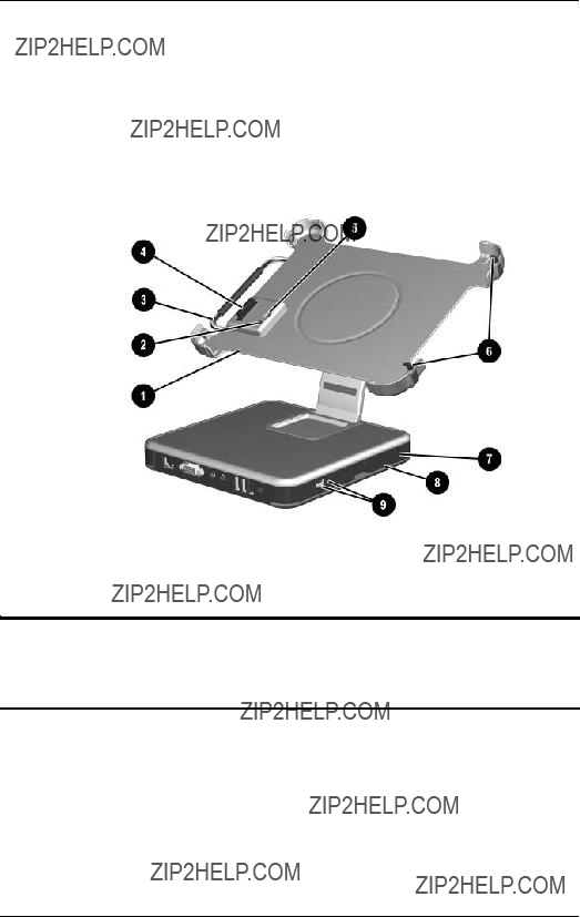
???Keyboard with pointing stick device

???Integrated communication???one of the following:

??? Type III Mini PCI 56Kbps, v.90/v.92 modem, wireless LAN 802.11b, and 10/100 network interface card (NIC)

??? Type III Mini PCI 56Kbps, v.90/v.92 modem and 10/100 network interface card (NIC)

???Integrated Bluetooth?? on select models only

???One Type III PC Card slot with support for both 32-bit (CardBus) and 16-bit PC Cards

???One Secured Digital (SD) Memory Card slot

???External 65 W AC adapter with power cord

???Six-cell, 11.1 V, 3.6-Ah Li-Ion battery pack

???80-, 60-, 40-, or 30-GB high-capacity hard drive, varying by tablet PC model

???Support for the following drives through the MultiBay (with optional External MultiBay or Docking Station):

??? 1.44-MB diskette drive

??? 24X Max CD-ROM drive

??? 8X Max CD-RW drive
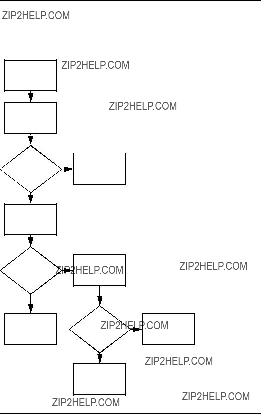
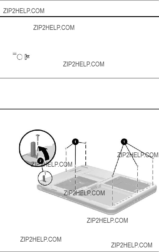
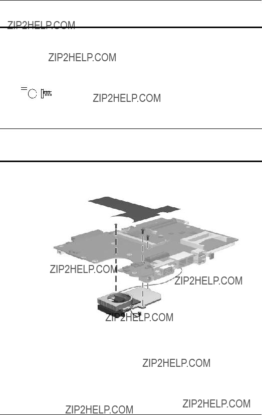
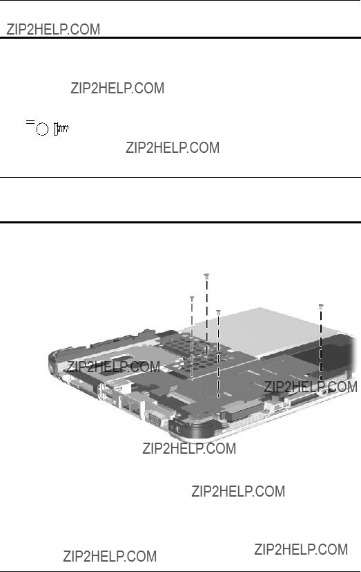
Product Description

???8X Max DVD-ROM drive

???8X Max DVD/CD-RW Combo Drive

???80-, 60-, 40-, or 30-GB hard drive

???Support for the following connectors on the tablet PC:

???RJ-45 network

???RJ-11 modem

???Universal Serial Bus

???External monitor

???AC power

???Stereo line out/headphone

???Mono microphone

???External MultiBay

???Keyboard

???Docking Station

???Support for the following connectors on the optional Docking Station:

???External MultiBay

???RJ-45 network

???USB

???External monitor

???AC power

???Stereo line out/headphone

Product Description

1.3 Clearing a Password

If the tablet PC you are servicing has an unknown password, follow these steps to clear the password. These steps also clear CMOS:

1.Remove the battery pack and Mini PCI communications memory module slot cover. Refer to Section 5.3, ???Preparing the Tablet PC for Disassembly,??? for more information.

2.Remove the RTC battery (refer to Section 5.4, ???Real Time Clock Battery???).

3.Wait approximately 5 minutes.

4.Replace the RTC battery and reassemble the tablet PC. Do not reinsert the battery pack at this time.

5.Connect AC power to the tablet PC.

6.Turn on the tablet PC.

All passwords and all CMOS settings have been cleared.

Product Description

1.4 Power Management

The tablet PC comes with power management features that extend battery operating time and conserve power. The tablet PC supports the following power management features:

???Suspend

???Hibernation

???User customization of settings

???Hotkeys for setting level of performance

???Smart battery that provides an accurate battery power gauge

???Battery calibration

???Lid switch Suspend/Resume

???Power/Suspend button

???Advanced Configuration and Power Management (ACP) compliance

Product Description

1.5 Tablet PC External Components

The external components on the front of the tablet PC are shown in the following illustration and described in Table 1-47.

Front Components

Product Description

Table 1-47

Front Components (Continued)

Product Description

The tablet PC top components are shown in the following illustration and described in Table 1-48.

Top Components

Table 1-48

Top Components

Product Description

Table 1-48

Top Components (Continued)

*If an optional External MultiBay is connected to the USB port, the External MultiBay must also be connected to external power. If an External MultiBay is connected to the External MultiBay connector, it is not necessary to connect the External MultiBay to external power.

Product Description

The tablet PC left-side components are shown in the following illustration and described in Table 1-49.

Left-Side Components

Table 1-49

Left-Side Components

Product Description

Table 1-49

Left-Side Components (Continued)

Product Description

The tablet PC right-side components are shown in the following illustration and described in Table 1-50.

Right-Side Components

??? In Windows, functions like esc on a standard keyboard.

Product Description

Table 1-50

Right-Side Components (Continued)

Product Description

The tablet PC rear components are shown in the following illustration and described in Table 1-51.

Rear Components

Table 1-51

Rear Components

Product Description

The tablet PC bottom components are shown in the following illustration and described in Table 1-52.

Bottom Components

Product Description

Table 1-52

Bottom Components (Continued)

protector, or an optional tablet PC keyboard, from the universal attachment slots on the tablet PC.

Product Description

Table 1-52

Bottom Components (Continued)

Product Description

Table 1-52

Bottom Components (Continued)

board, such as a modem board or a combination modem and wireless board.

?? To prevent an unresponsive system and the display of a warning message, install only a Mini PCI device authorized for use by the governmental agency that regulates wireless devices in your country. If you install a device and then receive a warning message, remove the device to retore tablet PC functionality, and then contact Customer Care.

Product Description

1.6 Keyboard Components

The keyboard top components are shown in the following illustration and described in Table 1-53.

Keyboard Top Components

Table 1-53

Keyboard Top Components

Product Description

Table 1-53

Keyboard Top Components (Continued)

Product Description

The special keys on the keyboard are shown in the following illustration and described in Table 1-54.

Keyboard Special Keys

Product Description

Table 1-54

Keyboard Special Keys (Continued)

Product Description

The components on the rear and bottom of the optional keyboard are shown in the following illustration and described in Table 1-55.

Keyboard Rear and Bottom Components

Table 1-55

Keyboard Rear and Bottom Components

Product Description

1.7HP Tablet PC Docking Station Components

The upper and right-side components on the optional

HP Tablet PC Docking Station are shown in the following illustration and described in Table 1-56.

Docking Station Upper and Right-Side Components

Table 1-56

Docking Station Upper and

Right-Side Components

Product Description

Table 1-56

Docking Station Upper and

Right-Side Components (Continued)

Product Description

The front and left-side components on the optional Docking Station are shown in the following illustration and described in Table 1-57.

Docking Station Front and Left-Side Components

Table 1-57

Docking Station Front and Left-Side Components

Product Description

Table 1-57

Docking Station Front and Left-Side Components (Continued)

Product Description

1.8 Design Overview

This section presents a design overview of key parts and features of the tablet PC. Refer to Chapter 3, ???Illustrated Parts Catalog???" to identify replacement parts, and Chapter 5, ???Removal and Replacement Procedures," for disassembly steps.

The system board provides the following device connections:

???Memory module

???Hard drive

???Display

???Optional keyboard and pointing stick

???Audio

???Intel Pentium-M or Celeron processor

???Fan

???PC Card

???Secure Digital (SD) Memory card (not SDIO)

???External MultiBay

???Modem or modem/NIC

??CAUTION: To properly ventilate the tablet PC, allow at least a 7.6-cm (3-inch) clearance around the sides of the tablet PC.

The tablet PC uses an electric fan for ventilation. The fan is controlled by a temperature sensor and is designed to come on automatically when high temperature conditions exist. These conditions are affected by high external temperatures, system power consumption, power management, battery conservation configurations, battery fast charging, and software applications. Exhaust air is displaced through the ventilation grill located on the left side of the tablet PC.

2

Troubleshooting

??WARNING: Only authorized technicians trained by HP should repair this equipment. All troubleshooting and repair procedures are detailed to allow only subassembly/module level repair. Because of the complexity of the individual boards and subassemblies, do not attempt to make repairs at the component level or to make modifications to any printed wiring board. Improper repairs can create a safety hazard. Any indication of component replacement or printed wiring board modification may void any warranty or exchange allowances.

Troubleshooting

2.1 Setup and Diagnostics Utilities

Selecting Setup or HP Diagnostics

The tablet PC features 2 HP system management utilities:

???Setup???A system information and customization utility that can be used even when your operating system is not working or will not load. This utility includes settings that are not available in Windows.

???HP Diagnostics???A system information and diagnostic utility that is used within your Windows operating system. Use this utility whenever possible to

???Display system information.

???Test system components.

???Troubleshoot a device configuration problem in Windows Tablet PC Edition.

???It is not necessary to configure a device connected to a USB port on the tablet PC or to an optional Docking Station.

Using Setup

Information and settings in Setup are accessed from the File, Security, or Advanced menus:

1.Turn on or restart the tablet PC. Press F10 while the

F10 = ROM Based Setup message displays in the lower-left corner of the screen.

???To change the language, press F2.

???To view navigation information, press F1.

???To return to the Setup menu, press esc.

2.Select the File, Security, or Advanced menu.

Troubleshooting

3.To close Setup and restart the tablet PC:

??? Select File > Save Changes, and Exit and press enter.

- or -

??? Select File > Ignore Changes, and Exit and press enter.

4.When you are prompted to confirm your action, press F10.

Selecting from the File Menu

Troubleshooting

Selecting from the Security Menu

Troubleshooting

*Not applicable to SuperDisk LS-120 drives.

Troubleshooting

Selecting from the Advanced Menu

Troubleshooting

Table 2-3

Advanced Menu (Continued)

*Video modes vary even within regions. However, NTSC is common in

North America; PAL, in Europe, Africa, and the Middle East; NTSC-J, in Japan; and PAL-M, in Brazil. Other South and Central American regions may use NTSC, PAL, or PAL-M.

Troubleshooting

2.2Using HP Diagnostics for Windows

When you access HP Diagnostics for Windows, a scan of all system components is displayed on the screen before the HP Diagnostics window opens.

You can display more or less information from anywhere within HP Diagnostics for Windows by selecting Level on the menu bar.

HP Diagnostics for Windows is designed to test HP components. If third-party components are tested, the results may be inconclusive.

Obtaining, Saving or Printing

Configuration Information

1.Access HP Diagnostics by selecting Start > Control Panel >

Diagnostics for Windows.

2.Select Categories, and then select a category from the drop-down list.

???To save the information, select File > Save As.

???To print the information, select File > Print.

3.To close HP Diagnostics for Windows, select File > Exit.

Troubleshooting

Obtaining, Saving or Printing Diagnostic Test Information

1.Access HP Diagnostics by selecting Start > Control Panel >

Diagnostics for Windows.

2.Select the Test tab.

3.In the scroll box, select the category or device you want to test.

4.Select a test type:

???Quick Test???Runs a quick, general test on each device in a selected category.

???Complete Test???Performs maximum testing on each device in a selected category.

???Custom Test???Performs maximum testing on a selected device.

???To run all tests for your selected device, select

Check All.

???To run only the tests you select, select Uncheck All, and then select the check box for each test you want to run.

5.Select a test mode:

???Interactive Mode???Provides maximum control over the testing process. You determine whether the test was passed or failed. You might be prompted to insert or remove devices.

???Unattended Mode???Does not display prompts. If errors are found, they are displayed when testing is complete.

Troubleshooting

6.Select Begin Testing.

7.Select a tab to view a test report:

???Status tab???Summarizes the tests run, passed, and failed during the current testing session.

???Log tab???Lists tests run on the system, the number of times each test has run, the number of errors found on each test, and the total run time of each test.

???Error tab???Lists all errors found in the tablet PC, along with their error codes.

8.Select a tab to save the report:

???Log tab???Select Log tab Save.

???Error tab???Select Error tab Save.

9.Select a tab to print the report:

Log tab???Select File > Save As, and then print the file from your folder.

Troubleshooting

Troubleshooting Flowcharts

2.14???Flowchart 2.14???No OS Loading from CD-ROM or DVD-ROM Drive.???

Troubleshooting

Flowchart 2.1???Initial Troubleshooting

Begin troubleshooting.

N

Y

Troubleshooting

Flowchart 2.2???No Power, Part 1

No Power

(power LED

is off).

Remove from Docking Station (if applicable).

Y

Power up

in DockingDone Station?

N

1.Reset the power cables in the Docking Station and at the AC outlet.

2.Ensure the AC power source is active.

*NOTES:

1.On some models there is a separate reset button.

2.On some models the tablet PC may be reset using the Suspend switch and either the lid switch or the main power switch.

Troubleshooting

Flowchart 2.3???No Power, Part 2

Continued from

Flowchart 2.2???No

Power, Part 1

Visually check for debris in battery socket and clean if necessary.

Y

N

Check battery by recharging, moving it to another tablet PC, or replacing it.

N

Replace

Power on? power supply (if applicable).

Y

N

Y

Done

Troubleshooting

Flowchart 2.4???No Power, Part 3

Continued from

Flowchart 2.3???No

Power, Part 2.

Plug directly into AC outlet.

Y

Power LED

on? Done

N

Reseat AC adapter in tablet PC and at power source.

Troubleshooting

Flowchart 2.5???No Power, Part 4

Continued from

Flowchart 2.4???No

Power, Part 3.

Open tablet PC.

N

Power on?

Y

Done

Replace the following items (if applicable). Check tablet PC operation after each replacement:

1.Internal DC-DC converter*

2.Internal AC adapter

3.Processor board*

4.System board*

*NOTE: Replace these items as a set to prevent shorting out among components.

Troubleshooting

Flowchart 2.6???No Video, Part 1

Check for bent pins on cable.

Replace the following one at a time. Test after each replacement.

1.Cable between notebook and tablet PC display (if applicable)

2.Inverter board (if applicable)

3.Display

4.System board

Troubleshooting

Flowchart 2.7???No Video, Part 2

Continued from

Flowchart 2.6???No

Video, Part 1.

Troubleshooting

Flowchart 2.8???Nonfunctioning

Docking Station (if applicable)

Nonfunctioning

Docking Station.

Troubleshooting

Flowchart 2.9???No Operating System (OS) Loading

No OS loading.*

Reseat power cord in Docking Station and power outlet..

No OS loading from hard drive, go to

Flowchart 2.10???No OS Loading from

Hard Drive, Part 1.

No OS loading from diskette drive, go to Flowchart 2.13???No OS Loading from Diskette Drive.

No OS loading from CD-ROM or DVD-ROM drive, go to Flowchart 2.14???No OS Loading from CD-ROM or DVD-ROM Drive.

No OS loading from network, go to

Flowchart 2.20???No Network or Modem Connection.

*NOTE: Before beginning troubleshooting, always check cable connections, cable ends, and drives for bent or damaged pins.

Troubleshooting

Flowchart 2.10???No OS Loading from Hard Drive, Part 1

OS not loading from hard drive.

Y

Troubleshooting

Flowchart 2.11???No OS Loading from Hard Drive, Part 2

Continued from Flowchart 2.10???No OS Loading from Hard Drive, Part 1.

N

CD or diskette in drive?

Y

Y

Boot from hard drive?

N

N

Boot from diskette

drive?

Y

N

Hard drive accessible?

Y

Go to Flowchart 2.12???No OS Loading from Hard Drive, Part 3.

Troubleshooting

Flowchart 2.12???No OS Loading from Hard Drive, Part 3

Done

Replace hard drive.

Done

Troubleshooting

Flowchart 2.13???No OS Loading from Diskette Drive

Troubleshooting

Flowchart 2.14???No OS Loading from CD-ROM or DVD-ROM Drive

Y

Boots from

CD or DVD?

N

Reseat

drive.

Done

Troubleshooting

Flowchart 2.15???No Audio, Part 1

N

Y

Tablet PC in

Docking Station

(if applicable)?

N

Go to Flowchart 2.16???No

Audio, Part 2

Y

Replace the following Docking Station components one at a time as applicable. Check after each change.

1.Reset Docking Station audio cable.

2.Replace audio cable.

3.Replace speaker.

4.Replace Docking Station audio board.

5.Replace backplane board.

6.Replace I/O board.

Y

Go to

Flowchart

2.17???Nonfunctioni Audio? Done ng Device

N

Troubleshooting

Flowchart 2.16???No Audio, Part 2

Continued from

Flowchart 2.15???No

Audio, Part 1

N

Audio driver in OS configured?

Y

N

Correct drivers for application?

Y

Connect to external speaker.

N

Audio?

Y

Reload audio drivers.

Load drivers and set configuration in OS.

N

1. Replace internal speakers.

2. Replace audio board (if applicable).

3. Replace system board.

Troubleshooting

Flowchart 2.17???Nonfunctioning Device

Nonfunctioning

device.

Reseat device.

Troubleshooting

Flowchart 2.18???Nonfunctioning Keyboard

Keyboard not operating properly.

Connect tablet PC to good external keyboard.

Y

Reseat internal keyboard connector

(if applicable).

N

Replace internal OK?keyboard or

cable.

Y

Y

N

Replace system board.

Troubleshooting

Flowchart 2.19???Nonfunctioning Pointing Device

Pointing device not operating properly.

Connect tablet PC to good external pointing device.

Y

Reseat internal pointing device connector

(if applicable).

N

Replace internal OK?pointing device

or cable.

Y

Y

N

Replace system board.

Troubleshooting

Flowchart 2.20???No Network or

Modem Connection

No network or modem connection.

N

Network

or modem jack active?

Y

Y

Digital

line?

N

N

NIC/modem

configured

in OS?

Y

Disconnect all power from the tablet PC and open.

Reseat NIC/modem

(if applicable).

Replace jack or have jack activated.

Connect to nondigital line.

Reload drivers and reconfigure.

Y

OK?Done

N

Replace

NIC/modem (if applicable).

Y

OK?Done

N

Replace system board.

3

Illustrated Parts Catalog

This chapter provides an illustrated parts breakdown and a reference for spare part numbers and option part numbers.

3.1 Serial Number Location

When ordering parts or requesting information, provide the tablet PC serial number and model number located on the bottom of the tablet PC.

Serial Number Location

Illustrated Parts Catalog

3.2HP Compaq Tablet PC System Major Components

HP Compaq Tablet PC Major Components

Illustrated Parts Catalog

Table 3-1

Spare Parts: Tablet PC System Major Components

Illustrated Parts Catalog

Tablet PC Major Components

Illustrated Parts Catalog

Table 3-1

Spare Parts: HP Tablet PC System

Major Components (Continued)

8Wireless local area network (LAN) board

(Mini PCI, Type III)

Illustrated Parts Catalog

3.3Miscellaneous Cable Kit Components

Miscellaneous Cable Kit Components

Table 3-2

Miscellaneous Cable Kit Components

Spare Part Number 348335-001

Item Description

1Audio cable

2Inverter cable

3Digitizer cable

4Display panel cable

5Modem cable

Illustrated Parts Catalog

3.4Miscellaneous Plastics/Hardware Kit Components

Miscellaneous Plastics/Hardware Kit Contents

Table 3-3

Miscellaneous Plastics/Hardware Kit Components

Spare Part Number 348350-001

Item Description

1PC Card slot space saver

2SD Card slot space saver

3Connector cover

4Memory module/Mini PCI communications compartment cover

5Hard drive cover

6Keyboard release assembly

Illustrated Parts Catalog

3.5 Keyboard

Tablet PC Keyboard

Illustrated Parts Catalog

Table 3-4

Tablet PC Keyboard

Spare Part Number Information

Illustrated Parts Catalog

3.6Optional HP Tablet PC Docking Station

Optional HP Tablet PC Docking Station

Table 3-5

Optional HP Tablet PC Docking Station

Spare Part Number Information

Illustrated Parts Catalog

3.7HP Tablet PC Docking Station Components

HP Tablet PC Docking Station Components

Illustrated Parts Catalog

Table 3-6

HP Tablet PC Docking Station Components

Spare Part Number Information

Illustrated Parts Catalog

3.8 Miscellaneous

Table 3-7

Spare Parts: Miscellaneous (not illustrated)

??? Phillips M2.0 ?? 4.0

??? Phillips M2.0 ?? 5.0

??? Phillips M2.0 ?? 3.5

??? Torx M2.5 ?? 7.0

4

Removal and Replacement

Preliminaries

This chapter provides essential information for proper and safe removal and replacement service.

4.1 Tools Required

You need the following tools to complete the removal and replacement procedures:

???Magnetic screwdriver

???Torx T8 screwdriver

???Phillips P0 screwdriver

???Tool kit (includes connector removal tool, loopback plugs, and case utility tool)

4.2Service Considerations

The following sections include some of the considerations that you should keep in mind during disassembly and assembly procedures.

???As you remove each subassembly from the tablet PC, place the subassembly (and all accompanying screws) away from the work area to prevent damage.

Removal and Replacement Preliminaries

Plastic Parts

Using excessive force during disassembly and reassembly can damage plastic parts. Use care when handling the plastic parts. Apply pressure only at the points designated in the maintenance instructions.

Cables and Connectors

??CAUTION: When servicing the tablet PC, ensure that cables are placed in their proper locations during the reassembly process. Improper cable placement can damage the tablet PC.

Cables must be handled with extreme care to avoid damage. Apply only the tension required to unseat or seat the cables during removal and insertion. Handle cables by the connector whenever possible. In all cases, avoid bending, twisting, or tearing cables. Ensure that cables are routed in such a way that they cannot be caught or snagged by parts being removed or replaced. Handle flex cables with extreme care; these cables tear easily.

4.3Preventing Damage to Removable Drives

Removable drives are fragile components that must be handled with care. To prevent damage to the tablet PC, damage to a removable drive, or loss of information, observe the following precautions:

???Before removing or inserting a hard drive, shut down the tablet PC. If you are unsure whether the tablet PC is off or in Hibernation, turn on the tablet PC, and then shut it down.

???Before removing a diskette drive or optical drive, ensure that a diskette or disc is not in the drive. Ensure that the optical drive tray is closed.

Removal and Replacement Preliminaries

???Before handling a drive, ensure that you are discharged of static electricity. While handling a drive, avoid touching the connector.

???Handle drives on surfaces that have at least one inch of shock-proof foam.

???Avoid dropping drives from any height onto any surface.

???After removing a hard drive, optical drive, or diskette drive, place it in a static-proof bag.

???Avoid exposing a hard drive to products that have magnetic fields, such as monitors or speakers.

???Avoid exposing a drive to temperature extremes or liquids.

???If a drive must be mailed, place the drive in a bubble pack mailer or other suitable form of protective packaging and label the package ???Fragile: Handle With Care.???

4.4Preventing Electrostatic Damage

Many electronic components are sensitive to electrostatic discharge (ESD). Circuitry design and structure determine the degree of sensitivity. Networks built into many integrated circuits provide some protection, but in many cases the discharge contains enough power to alter device parameters or melt silicon junctions.

A sudden discharge of static electricity from a finger or other conductor can destroy static-sensitive devices or microcircuitry. Often, the spark is neither felt nor heard, but damage occurs.

An electronic device exposed to electrostatic discharge may not be affected at all and can work perfectly throughout a normal cycle. Or the device might function normally for a while, but because it has been degraded internally, it can fail prematurely.

Removal and Replacement Preliminaries

4.5Packaging and Transporting Equipment

Use the following grounding precautions when packaging and transporting equipment:

???To avoid hand contact, transport products in static-safe containers, such as tubes, bags, or boxes.

???Protect all electrostatic-sensitive parts and assemblies with conductive or approved containers or packaging.

???Keep electrostatic-sensitive parts in their containers until the parts arrive at static-free workstations.

???Place items on a grounded surface before removing items from their containers.

???Always be properly grounded when touching a sensitive component or assembly.

???Store reusable electrostatic-sensitive parts from assemblies in protective packaging or nonconductive foam.

???Use transporters and conveyors made of antistatic belts and roller bushings. Ensure that mechanized equipment used for moving materials is wired to ground and that proper materials are selected to avoid static charging. When grounding is not possible, use an ionizer to dissipate electric charges.

4.6Workstation Precautions

Use the following grounding precautions at workstations:

???Cover the workstation with approved static-dissipative material (see Table 4-2, ???Static-Shielding Materials???).

???Use a wrist strap connected to a properly grounded work surface, and use properly grounded tools and equipment.

???Use conductive field service tools, such as cutters, screwdrivers, and vacuums.

Removal and Replacement Preliminaries

???When using fixtures that must directly contact dissipative surfaces, only use fixtures made of static-safe materials.

???Keep the work area free of nonconductive materials, such as ordinary plastic assembly aids and Styrofoam.

???Handle electrostatic-sensitive components, parts, and assemblies by the case or PCM laminate. Handle these items only at static-free workstations.

???Avoid contact with pins, leads, or circuitry.

???Turn off power and input signals before inserting or removing connectors or test equipment.

4.7Grounding Equipment and Methods

Grounding equipment must include either a wrist strap or a foot strap at a grounded workstation.

???When seated, wear a wrist strap connected to a grounded system. Wrist straps are flexible straps with a minimum of one megohm ??10% resistance in the ground cords. To provide proper ground, wear a strap snugly against the skin at all times. On grounded mats with banana-plug connectors, connect a wrist strap with alligator clips.

???When standing, use foot straps and a grounded floor mat. Foot straps (heel, toe, or boot straps) can be used at standing workstations and are compatible with most types of shoes or boots. On conductive floors or dissipative floor mats, use foot straps on both feet with a minimum of one megohm resistance between the operator and ground. To be effective, the conductive strips must be worn in contact with the skin.

Removal and Replacement Preliminaries

Other grounding equipment recommended for use in preventing electrostatic damage includes:

???Antistatic tape

???Antistatic smocks, aprons, and sleeve protectors

???Conductive bins and other assembly or soldering aids

???Nonconductive foam

???Conductive tabletop workstations with ground cords of one megohm resistance

???Static-dissipative tables or floor mats with hard ties to the ground

???Field service kits

???Static awareness labels

???Material-handling packages

???Nonconductive plastic bags, tubes, or boxes

???Metal tote boxes

???Electrostatic voltage levels and protective materials

Removal and Replacement Preliminaries

Table 4-1 shows how humidity affects the electrostatic voltage levels generated by different activities.

Table 4-1

Typical Electrostatic Voltage Levels

Relative Humidity

??? A product can be degraded by as little as 700 V.

Table 4-2 lists the shielding protection provided by antistatic bags and floor mats.

Table 4-2

Static-Shielding Materials

5

Removal and Replacement

Procedures

This chapter provides removal and replacement procedures.

Torx T8 and Phillips P0 screws are removed during the disassembly of the tablet PC and the Docking Station. There are 38 screws, in 4 different sizes, that must be removed, replaced, and loosened when servicing the tablet PC. There are 20 screws, in 4 different sizes, that must be removed and replaced when servicing the Docking Station. Make special note of each screw size and location during removal and replacement.

Refer to Appendix C, ???Screw Listing,??? for detailed information on screw sizes, locations, and usage.

Removal and Replacement Procedures

5.1 Serial Number

Report the tablet PC serial number to HP when requesting information or ordering spare parts. The serial number is located on the bottom of the tablet PC.

Serial Number Location

Removal and Replacement Procedures

5.2 Disassembly Sequence Chart

Use the chart below to determine the section number to be referenced when removing tablet PC components.

Table 5-1

Disassembly Sequence Chart

5.3Preparing the tablet PC for disassembly

Removal and Replacement Procedures

5.3 Preparing the Tablet PC

for Disassembly

Perform the following steps before disassembling the tablet PC.

Before You Begin

1.Save your work, exit all applications, and shut down the tablet PC. If you are unsure whether the tablet PC is off or in Hibernation, turn the tablet PC on and then shut it down through the operating system.

2.Disconnect all external devices connected to the tablet PC.

3.Disconnect the power cord.

4.Position the tablet PC so that the SD Card and PC Card slots are toward you.

Removal and Replacement Procedures

5.Remove the SD Card and PC Card slot devices (if any) by following these steps:

a.Press the SD Card to release it from the base enclosure. (The card is ejected from the slot.)

Releasing the SD Card

Ejecting the SD Card

Removal and Replacement Procedures

b.Press the PC Card release button 1 to release the button from the base enclosure. Press the button a second time to eject the contents of the PC Card slot.

c.Remove the PC Card slot device 2 from the card slot.

???The PC Card slot space saver and SD Card slot space saver are included in the Miscellaneous Plastics/Hardware Kit, spare part number 348350-001.

Removing the PC Card Device

Removal and Replacement Procedures

6.Release the pen from the holder by pressing the end 1. Remove the pen from the holder 2.

7.Open the connector cover by pulling out and down on the notch 3.

Removing the Pen and Opening the Connector Cover

Removal and Replacement Procedures

Battery Pack

Spare Part Number Information

8.Remove the battery pack by following these steps:

a.Turn the tablet PC upside down, with the power switch and jog dial toward you.

b.Remove the optional PM2.0 ?? 3.0 retention screw 1 that secures the battery pack to the tablet PC.

c.Slide the battery release latch 2 toward the back of the tablet PC to release the battery pack.

d.Use the notch in the battery pack to lift the left side of the battery pack up and swing it to the right 3.

e.Remove the battery pack.

Removing the Battery Pack

Reverse the preceding procedures to install the battery pack.

Removal and Replacement Procedures

Mini PCI Communications Board

Spare Part Number Information

9.Remove the Mini PCI communications board by following these steps:

a.Remove the 2 PM2.0 ?? 3.0 screws 1 that secure the Mini PCI communications/memory module slot cover to the tablet PC.

b.Lift the back edge of the Mini PCI communications/ memory module slot cover up and swing it toward you 2.

c.Remove the Mini PCI communications/memory module slot cover.

???The Mini PCI communications/memory module slot cover is included in the Miscellaneous Plastics/Hardware Kit, spare part number 310678-001.

Removing the Memory Module/Mini PCI Communications

Compartment Cover

Removal and Replacement Procedures

d.Disconnect the 2 antenna cables 1 from the Mini PCI communications board.

e.Spread the retaining tabs 1 securing the Mini PCI communications board to the system board.

The edge of the Mini PCI communications board opposite the connector rises at a 45-degree angle.

f.Pull the Mini PCI communications board away from the connector at a 45-degree angle 3.

Removing the Mini PCI Communications Board

Reverse the preceding procedures to install the Mini PCI communications board.

Removal and Replacement Procedures

Memory Module

Spare Part Number Information

10.Remove the memory module by following these steps:

a.Remove the Mini PCI communications/memory module slot cover.

b.Spread the retaining tabs 1 securing the memory module 2 to the system board. The end of the memory module opposite the connector rises at a 45-degree angle.

c.Pull the memory module away from the connector at a 45-degree angle 3.

Removing the Memory Module

Reverse the preceding procedures to install the memory module.

Removal and Replacement Procedures

5.4 Real Time Clock Battery

Real Time Clock (RTC)Battery

Spare Part Number Information

Perform the following steps to remove the RTC battery:

1.Prepare the tablet PC for disassembly (see Section 5.3, ???Preparing the Tablet PC for Disassembly???).

2.Turn the tablet PC upside down, with the power switch and jog dial toward you.

3.Disconnect the RTC battery cable from the system board 1.

4.Remove the RTC battery from the tablet PC 2.

Removing the RTC Battery

Reverse the preceding procedures to install the RTC battery.

Remove the hard drive by following these steps:

1.Prepare the tablet PC for disassembly (see ???Preparing the Tablet PC for Disassembly,???).

2.Turn the tablet PC upside down with the power switch and jog dial toward you.

Removal and Replacement Procedures

3.Remove the 2 PM2.0 ?? 3.0 screws 1 that secure the hard drive cover to the tablet PC.

4.Lift the front edge of the cover up and swing the cover back 2.

5.Remove the hard drive cover.

???The hard drive cover is included in the Miscellaneous Plastics/Hardware Kit, spare part number 348350-001.

Removing the Hard Drive Cover

Removal and Replacement Procedures

6.Use the tab 1 on the right side of the hard drive to slide the drive to the right 2 and disconnect it from the system board.

7.Remove the hard drive from the tablet PC 3.

Removing the Hard Drive

Reverse the preceding procedures to install the hard drive.

Removal and Replacement Procedures

5.6 Display Panel Assembly

Display Panel Assembly Components

Spare Part Number Information

To remove and disassemble the display panel assembly:

1.Prepare the tablet PC for disassembly (see Section 5.3, ???Preparing the Tablet PC for Disassembly???).

2.Remove RTC battery (see Section 5.4, ???Real Time Clock Battery???).

3.Remove the hard drive (see Section 5.5, ???Hard Drive???).

4.Turn the tablet PC upside down with the power switch and jog dial toward you.

Removal and Replacement Procedures

5.Remove the 6 TM2.5 ?? 7.0 screws 1 that secure the display panel assembly to the tablet PC.

6.Open the bottom tilt foot 2 and remove the TM2.5 ?? 7.0 screw 3 that secures the display panel assembly to the tablet PC.

Removing the Display Panel Assembly Screws

Removal and Replacement Procedures

7.Slide and hold the keyboard release latch 1 to the right.

8.Remove the TM2.5 ?? 7.0 screw 2 that secures the display panel assembly to the tablet PC.

9.Lift the edge of the insulator nearest the edge of the tablet 3.

10.Disconnect the digitizer cable 4 in the hard drive bay.

Removing the Display Panel Assembly Screw and Disconnecting the Digitizer Cable

Removal and Replacement Procedures

11.Separate the panel from the base enclosure along the edge farthest from you. Swing the panel toward you until it is resting on the table.

Separating the Panel and Base Enclosure

Removal and Replacement Procedures

12.Release the ZIF connector 1 to which the audio cable is attached and disconnect the cable 2.

13.Release the ZIF connector 3 to which the inverter cable is attached and disconnect the cable 4.

14.Separate the panel and the base enclosure.

Disconnecting the Audio and Inverter Cables

Reverse the preceding procedures to reassemble and install the display panel assembly.

Removal and Replacement Procedures

15.Remove the bridge battery by following these steps:

a.Disconnect the bridge battery cable 1 from the panel inverter board.

b.Remove the bridge battery 2 from the panel bezel.

Removing the Bridge Battery

Removal and Replacement Procedures

16.Remove the digitizer by following these steps:

a.Release the ZIF connector 1 to which the digitizer cable is attached and disconnect the cable from the system board 2.

b.Swing the 2 flex cables 3 to the right.

Disconnecting the Digitizer Cable.

Removal and Replacement Procedures

c.Remove the 2 PM 2.0 x 4.5 screws on the left side and the screw at the front of the digitizer panel that secure the bracket to the panel assembly.

Removing the Bracket Screws

Removal and Replacement Procedures

d.Remove the 2 PM2.0 ?? 4.5 screws 1 that secure the digitizer to the display panel assembly.

e.Lift the front edge of the digitizer 2 and slide it out 3 of the display panel.

Removing the Digitizer

Removal and Replacement Procedures

5.7 System Board

System Board

Spare Part Number Information

Perform the following steps to remove the system board:

1.Prepare the tablet PC for disassembly (see Section 5.3, ???Preparing the Tablet PC for Disassembly???).

2.Remove the hard drive (see Section 5.5, ???Hard Drive???).

3.Remove the RTC battery (see Section 5.4, ???Real Time Clock Battery???).

4.Remove the display panel assembly (see Section 5.6, ???Display Panel Assembly???).

Removal and Replacement Procedures

5.Remove the Bluetooth module by following these steps:

a.Position the tablet PC base enclosure so that the heat sink grille is toward you.

b.Disconnect the Bluetooth module connector from the system board 1.

c.Slide the Bluetooth module 2 away from you and lift it away from the base enclosure.

Removing the Bluetooth Wireless Module

Removal and Replacement Procedures

6.Remove the 4 screws 1 that secure the shield and system board to the base enclosure.

7.Lift the shield from the system board 2.

8.Separate the adhesive 3 from the system board.

Removing the System Board Shield

Removal and Replacement Procedures

9.Release the ZIF connector 1 to which the audio cable is attached and disconnect the cable from the system board.

10.Release the ZIF connector 2 to which the button board cable is attached and disconnect the cable 3 from the system board.

Disconnecting the Audio and Button Board ZIF Connectors

Removal and Replacement Procedures

11.Remove the system main memory by following these steps:

a.Spread the retaining tabs 1 securing the main memory board to the system board.

The end of the memory board opposite the connector rises at a 45-degree angle.

b.Pull the memory module away from the connector at a 45-degree angle 2.

Removing the Main Memory Module

Removal and Replacement Procedures

12.Remove the modem board by following these steps:

a.Disconnect the modem module connector from the system board 1.

b.Remove the PM2.0 ?? 4.5 screw 2 that secures the modem board to the system board.

c.Lift the modem and cable assembly from the base enclosure 3.

Removing the Modem Board

Removal and Replacement Procedures

13.Remove the TM2.5 ?? 4.5 screw 1 that secures the keyboard release assembly to the base enclosure.

14.Remove the 4 TM2.5 ?? 5.5 screws 2 that secure the keyboard release assembly to the base enclosure.

15.Lift the keyboard release assembly straight up 3 and remove it from the base enclosure.

Removing the Keyboard Release Assembly

Removal and Replacement Procedures

???When installing the keyboard release assembly, make sure the actuator tab 1 in the base enclosure is in the leftmost position. After this tab is positioned properly, install the keyboard release assembly 2 and screws 3 4.

Installing the Keyboard Release Assembly

16.Position the base enclosure so the heat sink grille is to your right.

17.Remove the 5 PM2.0 ?? 4.5 screws that secure the system board to the base enclosure.

Removal and Replacement Procedures

18.Use the heat sink grill 1 to lift the right edge of the system board 2 until it rests at a 45-degree angle.

19.Slide the system board away from the base enclosure at an angle 3 to remove it.

Removing the System Board

Reverse the preceding procedures to install the system board.

Removal and Replacement Procedures

5.8 Fan and Heat Sink

Fan and Heat Sink

Spare Part Number Information

???The fan and heat sink are included with the system board. A fan and heat sink can also be ordered separately using spare part number 310665-001.

Perform the following steps to remove the fan and heat sink:

1.Prepare the tablet PC for disassembly (see Section 5.3, ???Preparing the Tablet PC for Disassembly???).

2.Remove the display panel assembly (see Section 5.6, ???Display Panel Assembly???).

3.Remove the system board (see Section 5.7, ???System Board???).

Removal and Replacement Procedures

4.Remove the Mylar system board shield 1.

5.Disconnect the fan cable from the system board.

6.Remove the 3 PM2.0 ?? 4.5 screws 2 that secure the fan and heat sink to the system board.

7.Lift the system board 3 straight up. The fan and heat sink 4 will remain resting on the work surface.

Removing the Fan and Heat Sink

Reverse the preceding procedures to install the EMI shield, fan, and heat sink.

Removal and Replacement Procedures

5.9 Optional HP Tablet PC

Docking Station

Optional HP Tablet PC Docking Station Components

Spare Part Number Information

Perform the following steps to disassemble the Docking Station:

1.Position the Docking Station upside down, resting on the docking stand, with the bottom case toward you.

2.Remove the 4 TM2.5 ?? 6.0 screws that secure the top case to the bottom case.

Removing the Top Case Screws

Removal and Replacement Procedures

3.Position the Docking Station right side up with the rear toward you and the docking stand swung all the way back.

4.Lift the left edge of the top case 1 until the rear edge of the case 2 disengages from the bottom case.

5.Remove the top case 3.

Removing the Top Case

Removal and Replacement Procedures

6.Disconnect the docking stand cable 1 from the board assembly 2.

Disconnecting the Docking Stand Cable

???Make sure the docking stand and pivot arm are supported before removing the following screws. The docking stand and pivot arm can fall if not supported.

Removal and Replacement Procedures

7.Remove the following screws:

???3 PM2.5 ?? 7.0 screws 1 that secure the cable bracket to the bottom case.

???1 PM2.5 ?? 11.0 screw 2 that secures the pivot arm hinge to the bottom case.

???3 PM2.5 ?? 7.0 screws 3 that secure the pivot arm hinge to the bottom case.

8.Remove the docking stand and pivot arm 4.

Removing the Docking Stand and Pivot Arm

Removal and Replacement Procedures

9.Disconnect the switch cable 1 from the board assembly.

10.Remove the 7 PM2.5 ?? 4.0 screws 2 that secure the board assembly to the bottom case.

Removing the Board Assembly Screws

Removal and Replacement Procedures

11.Lift the front edge of the board assembly 1 until it rests at an angle.

12.Slide the board assembly toward you 2 until the rear connectors clear the bottom case.

13.Lift the board assembly straight up 3 to remove it from the bottom case.

Removing the Board Assembly

Reverse the preceding procedures to assemble the Docking Station.

6

Specifications

This chapter provides physical and performance specifications.

Table 6-1

Tablet PC

Specifications

???Applicable product safety standards specify thermal limits for plastic surfaces. The tablet PC operates well within this range of temperatures.

Specifications

Specifications

Table 6-3

Hard Drives

*1 GB=1,073,741,824 bytes.

???System capability may differ.

???Actual drive specifications may differ slightly.

Certain restrictions and exclusions apply. Consult Customer Care for details.

Specifications

Table 6-3

Hard Drives (Continued)

*1 GB=1,073,741,824 bytes.

???System capability may differ.

???Actual drive specifications may differ slightly.

Certain restrictions and exclusions apply. Consult Customer Care for details.

Specifications

Table 6-4

Diskette Drive

(For Use Only in the Docking Station or External MultiBay)

Specifications

Table 6-5

CD-ROM Drive

(For Use Only in the Docking Station or External MultiBay)

Specifications

Table 6-6

DVD-ROM Drive

(For Use Only in the Docking Station or External MultiBay)

Specifications

Table 6-7

DVD/CD-RW Combo Drive

(For Use Only in the Docking Station or External MultiBay)

Specifications

Temperature

32??F to 104??F 14??F to 122??F -4??F to 140??F

Specifications

??? PC Card controller can use DMA 1, 2, or 5.

Specifications

???PC Cards may assert IRQ3, IRQ4, IRQ5, IRQ7, IRQ9, IRQ10, IRQ11, or IRQ15. Either the infrared or the serial port may assert IRQ3 or IRQ4.

*Default configuration; audio possible configurations are IRQ5, IRQ7, IRQ9, IRQ10, or none.

Specifications

Table 6-12

System I/O Addresses

I/O Address (hex) System Function (shipping configuration)

Specifications

Table 6-12

System I/O Addresses (Continued)

I/O Address (hex) System Function (shipping configuration)

Specifications

Table 6-12

System I/O Addresses (Continued)

I/O Address (hex) System Function (shipping configuration)

Specifications

Table 6-13

System Memory Map

A

Connector Pin Assignments

Table A-1

RJ-45 Network Interface

Connector Pin Assignments

Table A-2

RJ-11 Modem

Table A-3

Universal Serial Bus

Connector Pin Assignments

Table A-4

External Monitor

Connector Pin Assignments

Table A-5

Stereo Speaker/Headphone

Table A-6

Microphone

B

Power Cord Set Requirements

The wide range input feature of the tablet PC permits it to operate from any line voltage from 100 to 120 or 220 to 240 V AC.

The power cord set received with the tablet PC meets the requirements for use in the country where the equipment is purchased.

Power cord sets for use in other countries must meet the requirements of the country where the tablet PC is used. For more information on power cord set requirements, contact a service partner.

General Requirements

The following requirements apply to all countries:

???The length of the power cord set must be at least 1.5 meters (5.00 feet) a maximum of 2.0 meters (6.50 feet).

???All power cord sets must be approved by an acceptable accredited agency responsible for evaluation in the country where the power cord set will be used.

???The power cord set must have a minimum current capacity of 10 amps and a nominal voltage rating of 125 or 250 volts AC, as required by each country???s power system.

???The appliance coupler must meet the mechanical configuration of an EN 60 320/IEC 320 Standard Sheet C13 connector for mating with the appliance inlet on the back of the tablet PC.

Power Cord Set Requirements

Country-Specific Requirements

3-Conductor Power Cord

Set Requirements

1.The flexible cord must be <HAR> Type HO5VV-F, 3-conductor, 1.0 mm?? conductor size. Power cord set fittings (appliance coupler and wall plug) must bear the certification mark of the agency responsible for evaluation in the country where it will be used.

2.The flexible cord must be Type SPT-3 or equivalent, No. 18 AWG, 3-conductor. The wall plug must be a two-pole grounding type with a NEMA 5-15P (15 A, 125 V) or NEMA 6-15P (15 A, 250 V) configuration.

3.The appliance coupler, flexible cord, and wall plug must bear a ???T??? mark and registration number in accordance with the Japanese Dentori Law. The flexible cord must be Type VCT or VCTF, 3-conductor, 1.00 mm?? conductor size. The wall plug must be a two-pole grounding type with a Japanese Industrial Standard C8303 (7 A, 125 V) configuration.

Power Cord Set Requirements

3-Conductor Power Cord

Set Requirements (Continued)

1.The flexible cord must be <HAR> Type HO5VV-F, 3-conductor, 1.0 mm?? conductor size. Power cord set fittings (appliance coupler and wall plug) must bear the certification mark of the agency responsible for evaluation in the country where it will be used.

2.The flexible cord must be Type SPT-3 or equivalent, No. 18 AWG, 3-conductor. The wall plug must be a two-pole grounding type with a NEMA 5-15P (15 A, 125 V) or NEMA 6-15P (15 A, 250 V) configuration.

3.The appliance coupler, flexible cord, and wall plug must bear a ???T??? mark and registration number in accordance with the Japanese Dentori Law. The flexible cord must be Type VCT or VCTF, 3-conductor, 1.00 mm?? conductor size. The wall plug must be a two-pole grounding type with a Japanese Industrial Standard C8303 (7 A, 125 V) configuration.

Screw Listing

C

Screw Listing

This appendix provides specification and reference information for the screws used in the tablet PC and the Docking Station. All screws listed in this appendix are available for the tablet PC in the Miscellaneous Screw Kit, spare part number 310674-001.

Screw Listing

Table C-1

Phillips M2.0 ?? 4.0 Screw

Where used:

1 1 screw that secures the battery pack to the tablet PC (documented in Section 5.3)

2 2 screws that secure the Mini PCI communications/memory module compartment cover to the tablet PC (documented in Section 5.3)

3 2 screws that secure the hard drive cover to the tablet PC (documented in Section 5.5)

Phillips M2.0 ?? 4.0 Screw Locations

Screw Listing

Table C-1

Phillips M2.0 ?? 4.0 Screw (Continued)

Where used:

4 screws that secure the display panel to the display bezel (documented in Section 5.6)

Phillips M2.0 ?? 4.0 Screw Locations

Screw Listing

Table C-2

Phillips M2.5 ?? 8.4 Screw

Where used:

1 7 screws that secure the display panel assembly to the tablet PC (documented in Section 5.6)

2 1 screw that secures the connector cover and display panel assembly to the tablet PC (documented in Section 5.6)

Torx M2.5 ?? 7.0 Screw Locations

Screw Listing

Table C-3

Phillips M2.5 ?? 6.5 Screw

Where used:

4 screws that secure the keyboard release assembly to the base enclosure (documented in Section 5.7)

Phillips M2.5 ?? 6.5 Screw Location

Screw Listing

Table C-4

Phillips M2.0 ?? 3.0 Screw

Where used:

4 screws that secure the display panel to the display bezel (documented in Section 5.6)

Phillips M2.0 ?? 3.0 Screw Locations

Screw Listing

Table C-5

Torx M2.5 ?? 7.4 Screw

Where used:

4 screws that secure the docking station top case to the bottom case (documented in Section 5.9)

Phillips M2.0 ?? 4.5 Screw Locations

Screw Listing

Table C-6

Phillips M2.0 ?? 4.0 Screw

Where used:

3 screws that secure the display panel bracket to the display panel assembly (documented in Section 5.6)

Phillips M2.0 ?? 4.0 Screw Locations

Screw Listing

Table C-7

Phillips M2.0 ?? 5.5 Screw

Where used:

1 screw that secures the display panel bracket to the display panel assembly (documented in Section 5.6)

Phillips M2.0 ?? 5.5 Screw Locations

Screw Listing

Table C-8

Phillips M2.5 ?? 4.9 Screw

Where used:

4 screws that secure the system board to the base enclosure (documented in Section 5.7)

Phillips M2.0 ?? 4.9 Screw Locations

Screw Listing

Table C-9

Phillips M2.0 ?? 5.5 Screw

Where used:

3 screws that secure the fan and heat sink to the system board (documented in Section 5.7)

Phillips M2.0 ?? 5.5 Screw Locations

Screw Listing

Table C-10

Phillips M2.0 ?? 3.5 Screw

Where used:

4 screws that secure the EMI shield to the base enclosure (documented in Section 5.7)

Phillips M2.0 ?? 3.5 Screw Locations

Screw Listing

Table C-11

Phillips M2.0 ?? 4.0 Screw

Where used:

1 screw that secures the switch board to the base enclosure (documented in Section 5.9)

Phillips M2.0 ?? 4.0 Screw Location

Screw Listing

Table C-12

Torx M2.5 ?? 8.0 Screw

Where used:

1 2 screws that secure the Docking Station pivot arm and cable bracket to the bottom case (documented in Section 5.9)

2 3 screws that secure the Docking Station pivot arm hinge to the bottom case (documented in Section 5.9)

Torx M2.5 ?? 8.0 Screw Locations

Screw Listing

Table C-13

Phillips M2.5 ?? 11.0 Screw

Where used:

1 screw that secures the Docking Station pivot arm hinge to the bottom case (documented in Section 5.9)

Phillips M2.5 ?? 12.0 Screw Location

A

AC adapter

spare part number 3???13 specifications 6???10

AC adapter light 1???37 AC power connector

Docking Station 1???57 tablet PC 1???39

AC power cord

spare part number 3???13 air vent 1???41, 1???46 alignment key 1???49 alignment key slot

keyboard 1???53 tablet PC 1???41 attachment release latch

(tablet PC) 1???46 attachment release switch

(keyboard) 1???53 audio line-in jack 1???57 audio line-out jack

Docking Station 1???57 tablet PC 1???44

audio troubleshooting 2???26

Index

B

base enclosure 3???5 illustrated 3???4

spare part number 3???5 battery light 1???36 battery pack

illustrated 3???4 location 1???47

quick check button 1???47 quick check lights 1???47 removal 5???8

spare part number 3???5 specifications 6???10

battery pack release latch 1???47 battery pack retention screw

1???47 bridge battery

removal 5???21

spare part number 3???3, 5???16

C

cables, service considerations 4???2

caps lock light 1???50

Index

CD-ROM drive

OS loading problems 2???25 specifications 6???7

components, Docking Station front 1???54

left-side 1???54 rear 1???56 right-side 1???56

components, keyboard front 1???51

rear panel 1???53 top 1???49

components, tablet PC bottom 1???44, 1???45 front 1???36

left side 1???40 right side 1???42 top 1???38

connector pin assignments external monitor connector

A???3

headphone jack A???4 microphone jack A???4 modem jack A???2 monitor connector A???3 network jack A???1 RJ-11 jack A???2

RJ-45 jack A???1 speaker jack A???4 USB port A???2

connectors, service considerations 4???2

D

design overview 1???58 diagnostics 2???2

configuration information 2???8

test information 2???9 digitizer

removal 5???24

spare part number 3???3, 5???16

digitizer cable disconnection 5???18 illustrated 3???2, 3???6

disassembly sequence chart 5???3

diskette drive

OS loading problems 2???24 specifications 6???6

display bezel with inverter, spare part number 3???3, 5???16

display inverter cable, illustrated 3???6

display panel assembly illustrated 3???2 removal 5???16

spare part number 3???3, 5???16

display panel cable 3???2, 3???6 display, specifications 6???3 DMA specifications 6???11 docking alignment brackets

(docking stand) 1???55

Index

docking alignment notches (keyboard) 1???50

docking alignment slots (tablet PC) 1???44

docking connector Docking Station 1???55 tablet PC 1???46

docking connector pass-through 1???50

docking eject pin 1???54 docking restraint latch

(Docking Station) 1???55 docking restraint latch recess

(tablet PC) 1???45 docking stand 1???54 docking stand and pivot arm

removal 5???39

spare part number 3???12, 5???36

Docking Station disassembly 5???36 illustrated 3???10

spare part number 3???10, 5???36

Docking Station board assembly

removal 5???41

spare part number 3???12, 5???36

troubleshooting 2???19 Docking Station bottom case, spare part number 3???12,

5???36

Docking Station components front 1???54

left-side 1???54

rear 1???56 right-side 1???56

Docking Station Miscellaneous Screw Kit

contents C???1

spare part number C???1 Docking Station spare parts

illustrated 3???11

part numbers 3???12, 5???36 Docking Station top case

removal 5???37

spare part number 3???12, 5???36

drives, preventing damage 4???2 DVD/CD-RW Combo Drive,

specifications 6???9 DVD-ROM drive

OS loading problems 2???25 specifications 6???8

E

electrostatic discharge 4???3, 4???7

e-mail launch button 1???43 external monitor port

on Docking Station 1???56 on tablet PC 1???39

pin assignments A???3 external MultiBay connector Docking Station 1???55

F

fan and heat sink removal 5???34

spare part number 3???3, 5???34

features 1???32

Index

feet 3???7

flowcharts, troubleshooting docking station 2???19 initial troubleshooting

2???12 keyboard 2???29

network or modem connection 2???31 no audio 2???26, 2???27 no operating system

loading 2???20

no OS loading from CD-ROM or DVD-ROM drive 2???25

no OS loading from diskette drive 2???24

no OS loading from hard drive 2???21, 2???22, 2???23

no power 2???13, 2???14, 2???15, 2???16

no video 2???16, 2???17, 2???18 nonfunctioning devices

2???28

pointing device 2???30 fn key 1???51

function keys 1???51

G

grounding equipment and methods 4???5

H

hard drive illustrated 3???4

OS loading problems 2???21 precautions 4???2

removal 5???13

spare part numbers 3???5 specifications 6???4

hard drive bay 1???47 hard drive cover

illustrated 3???2, 3???7 removal 5???13

hard drive retention screws 1???47

headphone jack, pin assignments A???4 headset jack 1???44 HP Diagnostics 2???8

I

I/O address specifications 6???13

illustrated parts catalog 3???1 interrupt specifications 6???12

J

jog dial 1???42

journal launch button 1???37

K

keyboard illustrated 3???8

spare part number 3???9 spare part numbers 3???8 troubleshooting 2???29

keyboard components front 1???51

rear panel 1???53 top 1???49

keyboard connector, tablet PC 1???41, 1???49

keyboard hooks 1???49 keyboard latch 1???50

Index

keyboard release assembly illustrated 3???7 removal 5???31

keypad keys 1???52

L

LAN connection lights 1???39 location 1???44

M

memory map specifications 6???16

memory module illustrated 3???4 removal 5???11

spare part number 3???5 memory module/Mini PCI

communications compartment 1???48

memory module/Mini PCI communications compartment cover retention screws 1???48

memory module/Mini PCI communications compartment cover, illustrated 3???2, 3???7

microphone 1???37 microphone jack location 1???44

pin assignments A???4 Mini PCI communications board, removal 5???10 Miscellaneous Cable Kit components 3???2, 3???6

spare part number 3???3, 3???6

Miscellaneous Plastics/Hardware Kit

components 3???7 spare part number 3???3

Miscellaneous Screw Kit contents 3???13, C???1 spare part number 3???13,

C???1 models 1???3 modem cable

disconnection 5???10 illustrated 3???2, 3???6 removal 5???36

modem jack pin assignments A???2

modem, troubleshooting 2???31 monitor port pin assignments

A???3 MultiBay 1???56

MultiBay release lever 1???55

N

network jack pin assignments A???1

network, troubleshooting 2???31 nonfunctioning device,

troubleshooting 2???19, 2???28 num lock light 1???50

O

operating system loading, troubleshooting 2???20

P

packing precautions 4???4 pad feet 1???47

parts catalog 3???1

Index

password, clearing 1???34 PC Card eject button 1???38 PC Card slot 1???38

PC Card slot space saver 3???7 pen holder

illustrated 3???2, 3???7 removal 1???38

pen holder push block assembly 3???2, 3???7

pen, spare part number 3???13 pivot arm 1???56

plastic parts 4???2 pointing device,

troubleshooting 2???30 pointing stick 1???50 pointing stick buttons 1???50 power cord set requirements

B???1

power management features 1???35

power switch 1???43

power, troubleshooting 2???13 power/Standby light 1???43 precautions

hard drive 4???2

product identification label 1???46

Q

Q menu button 1???43

R

release handle 1???54 removal and replacement

preliminaries 4???1 procedures 5???1

RJ-11 jack location 1???39

pin assignments A???2 RJ-45 jack

Docking Station 1???56 location 1???39

pin assignments A???1 tablet PC 1???39

rotate button 1???37 rotation disk 1???50

RTC (real time clock) battery illustrated 3???4

removal 5???12

spare part number 3???5, 5???12

RTC battery removal 5???12

S

screen protector slots keyboard 1???53 tablet PC 1???40

screw listings C???1 SD Card slot 1???39

SD Card slot space cover illustrated 3???7

spare part number 3???7 SD Card slot space saver 3???7 security cable slot

Docking Station 1???55 tablet PC 1???40

serial number 3???1, 5???2 service considerations 4???1 Setup

Advanced Menu 2???6 File Menu 2???3

Index

overview 2???2 Security Menu 2???4

spare part numbers 3???5 AC adapter 3???13 AC power cord 3???13 battery pack 3???5 cable kit 3???6

display components 3???3 docking station 3???10,

3???11, 3???12 fan 3???3 keyboard 3???9

memory module 3???5 pen 3???13 plastics/hardware kit 3???3,

3???7

RTC battery 3???5, 5???12 screw kit 3???13 speaker assembly 3???5 switch board 3???5 system board 3???3 wireless antenna 3???5 wireless LAN board 3???5

speaker assembly illustrated 3???4

spare part number 3???5 speaker cable, illustrated 3???2,

3???6 speaker jack

location 1???44

pin assignments A???4 speakers 1???44 specifications

AC adapter 6???10 battery 6???10 CD-ROM drive 6???7

diskette drive 6???6 display 6???3 DMA 6???11

DVD/CD-RW Combo Drive 6???9

DVD-ROM drive 6???8 hard drive 6???4

I/O addresses 6???13 interrupts 6???12 memory map 6???16 tablet PC 6???1

static shielding materials 4???7 stereo speaker jack, pin

assignments A???4 switch board

illustrated 3???4

spare part number 3???5 switch board cable

illustrated 3???2, 3???6 removal 5???20

system board illustrated 3???4 removal 5???25

spare part number 3???3, 5???25

system memory map 6???16

T

tab button 1???43 tablet PC components

bottom 1???44, 1???45 left side 1???40 right side 1???42 top 1???38

tablet PC components, front 1???36

Index

tablet PC specifications 6???1 tilt adjustment 1???49

tilt feet 1???45 tools required 4???1

transporting precautions 4???4 troubleshooting

audio 2???26

Docking Station 2???19 flowcharts 2???11

HP Diagnostics 2???8 keyboard 2???29 modem 2???31 network 2???31 nonfunctioning device

2???19, 2???28

operating system loading 2???20

overview 2???1 pointing device 2???30 power 2???13

Setup 2???2 video 2???17

U

universal alignment slots keyboard 1???53 tablet PC 1???41

Universal Serial Bus (USB) port

Docking Station 1???57 pin assignments A???2 tablet PC 1???38

V

video troubleshooting 2???17

W

Windows applications key 1???52

Windows logo key 1???52 Windows security button 1???43 wireless LAN board

illustrated 3???4

spare part number 3???5 wireless light 1???36 workstation precautions 4???4