HP EliteBook 2760p Tablet PC
Maintenance and Service Guide
HP EliteBook 2760p Tablet PC
Maintenance and Service Guide
?? Copyright 2011
Development Company, L.P.
Bluetooth is a trademark owned by its proprietor and used by
The information contained herein is subject to change without notice. The only warranties for HP products and services are set forth in the express warranty statements accompanying such products and services. Nothing herein should be construed as constituting an additional warranty. HP shall not be liable for technical or editorial errors or omissions contained herein.
Third Edition: June 2012
First Edition: May 2011
Document Part Number:

Safety warning notice
 WARNING! To reduce the possibility of
iii
iv Safety warning notice

Table of contents
v
vi
vii
viii

1 Product description
1

Supports the following WLAN formats:
??? Broadcom 4313GN 802.11b/g/n 1x1 WiFi Adapter
??? Broadcom 43224 AGN 802.11a/b/g/n 2x2 WiFi Adapter
??? Intel Centrino??
Supports ???no WLAN??? option
Two WLAN antennas built into display assembly
Integrated WWAN options by way of wireless module:
Two WWAN antennas
Supports "no WWAN" option
Integrated wireless personal area network (WPAN) options by way of 2.1
Bluetooth?? module:
Supports ???no WPAN??? option
Broadcom Bluetooth
3

Preinstalled with Microsoft?? Office:
Windows 7 Professional 32 or 64 with Microsoft?? Office 2010 Personal (Japan only)
Windows 7 Professional 32 or 64 with Microsoft Office 2010 Professional (Japan only)
Windows 7 Professional 32 or 64 with Microsoft Office 2010 Home and Business (Japan only)
Windows 7 Professional 32 or 64 with Microsoft Office 2010 Starter (excludes Japan)
Windows 7 Home Premium 32 or 64 with Microsoft Office 2010 Personal (Japan only)
Windows 7 Home Premium 32 or 64 with Microsoft Office 2010 Professional (Japan only)
Windows 7 Home Premium 32 or 64 with Microsoft Office 2010 Home and Business (Japan only)
Windows 7 Home Premium 32 or 64 with Microsoft Office 2010 Starter (excludes Japan)
Restore Media:
Windows 7 Professional 32 or 64
Windows 7 Home Premium 32 or 64

5

2 External component identification
Top
TouchPad

Lights
Top 7


Buttons
Top 9

Keys

Front
Front 11

Right
deterrent, but it may not prevent the computer from being mishandled or stolen.
Left
NOTE: A wireless network must be set up in order to establish a wireless connection.
Left 13

Display

*The antennas are not visible from the outside of the computer. For optimal transmission, keep the areas immediately around the antennas free from obstructions. To see wireless regulatory notices, refer to the section of the Regulatory, Safety, and Environmental Notices that applies to your country or region. These notices are located in Help and Support.
Display 15

Rear
*To protect your work and the system, the ctrl+alt+delete command cannot be entered using the ctrl, alt, and del keys on the

Bottom
Bottom 17

3 Illustrated parts catalog
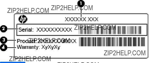
Serial number label location
When ordering parts or requesting information, the serial number label, located inside the battery bay, provides important information that you may need when contacting technical support.

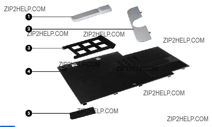
Computer major components

(2)Display assembly (includes 2 WLAN antenna transceivers and cables and 2 WWAN antenna transceivers and cables)
(3)Hinge cover assembly (included in the Plastics Kit, spare part number
(4)Keyboard with TouchPad and pointing stick (includes buttons and cables)

(7)TouchPad button board (included with the top cover assembly
(8)TouchPad button board bracket (included with the top cover assembly
(13)Security lock
(16)System board (includes replacement thermal material)
For use in all countries and regions except Russia and the People's Republic of China:

Bluetooth module cable is included in the Cable Kit, spare part number
Cable Kit on page 25 for more Cable Kit spare part number information.
(20)Bluetooth cable (included in the Cable Kit, spare part number
(21)QuickWeb button (included in the top cover assembly, spare part number
(24)Hard drive (includes bracket)
(25)Memory module
Plastics Kit

Cable Kit

Mass storage devices

Miscellaneous parts

???Phillips 2.5??8.0 captive screw
???Phillips 2.0??7.0 captive screw
???Phillips 2.0??3.0 captive screw
???Phillips 3.0??2.5 screw
???Phillips 2.5??3.0 screw
???Phillips 2.5??6.0 screw
???Phillips 2.0??4.0 screw
???Phillips 2.0??3.5 screw
???Phillips 2.0??3.0 screw
???Phillips 2.0??2.0 screw
???Phillips 1.5??1.5 Panhead screw
???Torx 8M2.2??7.0 screw
???Torx 8M2.2??5.0 screw

Sequential part number listing
People's Republic of China, the Congo, Croatia, Cyprus, the Czech Republic, Denmark, Djibouti,
Egypt, Equatorial Guinea, Estonia, Finland, France, Gabon, Gambia, Germany, Ghana, Gibraltar,
Greece, Guinea,
Italy, the Ivory Coast, Japan, Jordan, Kenya, Kiribati, Kuwait, Kyrgyzstan, Laos, Latvia, Lebanon,
Liberia, Liechtenstein, Lithuania, Luxembourg, Madagascar, Malaysia, Mali, Mauritania, Mauritius,
Montenegro, Morocco, Mozambique, Namibia, Nepal, the Netherlands, New Zealand, Niger,
Nigeria, Norway, Oman, Pakistan, the Philippines, Poland, Portugal, Qatar, Romania, Russia,
Rwanda, Sao Tome and Principe, Saudi Arabia, Senegal, Serbia, Sierra Leone, Singapore,
Slovakia, Slovenia, South Africa, South Korea, Spain, Sri Lanka, Switzerland, Syria, Taiwan,
Tanzania, Thailand, Togo, Tunisia, Turkey, the United Arab Emirates, the United Kingdom, Vietnam,
Yemen, and Zimbabwe

module cable is included in the Cable Kit, spare part number


4Removal and replacement procedures
Preliminary replacement requirements
Tools required
You will need the following tools to complete the removal and replacement procedures:
???
???Phillips P0 and P1 screwdrivers
???Torx T8 screwdriver
Service considerations
The following sections include some of the considerations that you must keep in mind during disassembly and assembly procedures.


 NOTE: As you remove each subassembly from the computer, place the subassembly (and all accompanying screws) away from the work area to prevent damage.
Plastic parts
CAUTION: Using excessive force during disassembly and reassembly can damage plastic parts. Use care when handling the plastic parts. Apply pressure only at the points designated in the maintenance instructions.

Cables and connectors
CAUTION: When servicing the computer, be sure that cables are placed in their proper locations during the reassembly process. Improper cable placement can damage the computer.
Cables must be handled with extreme care to avoid damage. Apply only the tension required to unseat or seat the cables during removal and insertion. Handle cables by the connector whenever possible. In all cases, avoid bending, twisting, or tearing cables. Be sure that cables are routed in such a way that they cannot be caught or snagged by parts being removed or replaced. Handle flex cables with extreme care; these cables tear easily.
Drive handling
CAUTION: Drives are fragile components that must be handled with care. To prevent damage to the computer, damage to a drive, or loss of information, observe these precautions:
Before removing or inserting a hard drive, shut down the computer. If you are unsure whether the computer is off or in Hibernation, turn the computer on, and then shut it down through the operating system.
Before handling a drive, be sure that you are discharged of static electricity. While handling a drive, avoid touching the connector.
Before removing a diskette drive or optical drive, be sure that a diskette or disc is not in the drive and be sure that the optical drive tray is closed.
Handle drives on surfaces covered with at least one inch of
Avoid exposing a hard drive to products that have magnetic fields, such as monitors or speakers. Avoid exposing a drive to temperature extremes or liquids.
If a drive must be mailed, place the drive in a bubble pack mailer or other suitable form of protective packaging and label the package ???FRAGILE.???

Grounding guidelines
Electrostatic discharge damage
Electronic components are sensitive to electrostatic discharge (ESD). Circuitry design and structure determine the degree of sensitivity. Networks built into many integrated circuits provide some protection, but in many cases, ESD contains enough power to alter device parameters or melt silicon junctions.
A discharge of static electricity from a finger or other conductor can destroy
An electronic device exposed to ESD may not be affected at all and can work perfectly throughout a normal cycle. Or the device may function normally for a while, and then degrade in the internal layers, reducing its life expectancy.
 CAUTION: To prevent damage to the computer when you are removing or installing internal components, observe these precautions:
Keep components in their
Before touching an electronic component, discharge static electricity by using the guidelines described in this section.
Avoid touching pins, leads, and circuitry. Handle electronic components as little as possible. If you remove a component, place it in an
The following table shows how humidity affects the electrostatic voltage levels generated by different activities.
 CAUTION: A product can be degraded by as little as 700 V.
Typical electrostatic voltage levels
Packaging and transporting guidelines
Follow these grounding guidelines when packaging and transporting equipment:
???To avoid hand contact, transport products in
???Protect
???Keep
???Place items on a grounded surface before removing items from their containers.
???Always be properly grounded when touching a component or assembly.
???Store reusable
???Use transporters and conveyors made of antistatic belts and roller bushings. Be sure that mechanized equipment used for moving materials is wired to ground and that proper materials are selected to avoid static charging. When grounding is not possible, use an ionizer to dissipate electric charges.
Workstation guidelines
Follow these grounding workstation guidelines:
???Cover the workstation with approved
???Use a wrist strap connected to a properly grounded work surface and use properly grounded tools and equipment.
???Use conductive field service tools, such as cutters, screwdrivers, and vacuums.
???When fixtures must directly contact dissipative surfaces, use fixtures made only of
???Keep the work area free of nonconductive materials, such as ordinary plastic assembly aids and Styrofoam.
???Handle
???Avoid contact with pins, leads, or circuitry.
???Turn off power and input signals before inserting or removing connectors or test equipment.

Equipment guidelines
Grounding equipment must include either a wrist strap or a foot strap at a grounded workstation.
???When seated, wear a wrist strap connected to a grounded system. Wrist straps are flexible straps with a minimum of one megohm ??10% resistance in the ground cords. To provide proper ground, wear a strap snugly against the skin at all times. On grounded mats with
???When standing, use foot straps and a grounded floor mat. Foot straps (heel, toe, or boot straps) can be used at standing workstations and are compatible with most types of shoes or boots. On conductive floors or dissipative floor mats, use foot straps on both feet with a minimum of one megohm resistance between the operator and ground. To be effective, the conductive strips must be worn in contact with the skin.
The following grounding equipment is recommended to prevent electrostatic damage:
???Antistatic tape
???Antistatic smocks, aprons, and sleeve protectors
???Conductive bins and other assembly or soldering aids
???Nonconductive foam
???Conductive tabletop workstations with ground cords of one megohm resistance
???
???Field service kits
???Static awareness labels
???
???Nonconductive plastic bags, tubes, or boxes
???Metal tote boxes
???Electrostatic voltage levels and protective materials
The following table lists the shielding protection provided by antistatic bags and floor mats.
Component replacement procedures
This chapter provides removal and replacement procedures.
There are as many as 43 screws in 12 different sizes, that must be removed, replaced, or loosened when servicing the computer. Make special note of each screw size and location during removal and replacement.
Service tag
When ordering parts or requesting information, provide the computer serial number and model description provided on the service tag.

Computer feet
The computer feet are

Pen
Remove the pen:
1.Position the computer
2.Pull the loop on the tether until it is large enough to pass the pen through it, and then pull the pen through the loop (1).
3.Remove the pen and tether from the computer (2).
Reverse this procedure to install the pen.
Battery
Before disassembling the computer, follow these steps:
1.Shut down the computer. If you are unsure whether the computer is off or in Hibernation, turn the computer on, and then shut it down through the operating system.
2.Disconnect all external devices connected to the computer.
3.Disconnect the power from the computer by first unplugging the power cord from the AC outlet, and then unplugging the AC adapter from the computer.
Remove the battery:
1.Turn the computer
2.Slide the battery release latch (1) to release the battery.
3.Pivot the edge of the battery upward (2) and remove it from the computer (3).
To insert the battery, insert the front edge of the battery into the battery bay and pivot the rear edge of the battery downward until it is seated. The battery release latch automatically locks the battery into place.

Service access cover
 NOTE: The service access cover is included in the Plastics Kit, spare part number
Before removing the service access cover, follow these steps:
1.Shut down the computer. If you are unsure whether the computer is off or in Hibernation, turn the computer on, and then shut it down through the operating system.
2.Disconnect all external devices connected to the computer.
3.Disconnect the power from the computer by first unplugging the power cord from the AC outlet, and then unplugging the AC adapter from the computer.
4.Remove the battery (see Battery on page 43)
Remove the service access cover:
1.Position the computer
2.Loosen the three Phillips M2.0x3.0 captive screws (1) that secure the service access cover to the computer.
3.Lift the rear edge of the service access cover (2) until it rests at an angle, and then remove the cover.
Reverse this procedure to install the service access cover.

Primary memory module
Update BIOS before adding memory modules
Before adding new memory, make sure you update the computer to the latest BIOS.
CAUTION: Failure to update the computer to the latest BIOS prior to installing new memory may result in various system problems.
To update BIOS:
1.Navigate to www.hp.com.
2.Click Support & Drivers > click Drivers & Software.
3.In the Enter a product name/number box, type the computer model information, and then click Search.
4.Click the link for the computer model.
5.Select the operating system, and then click Next.
6.Under Step 2: Select a Download, click the BIOS link.
7.Click the link for the most recent BIOS.
8.Click the Download button, and then follow the
Before removing the memory module, follow these steps:
1.Shut down the computer. If you are unsure whether the computer is off or in Hibernation, turn the computer on, and then shut it down through the operating system.
2.Disconnect all external devices connected to the computer.
3.Disconnect the power from the computer by first unplugging the power cord from the AC outlet, and then unplugging the AC adapter from the computer.
4.Remove the following components:
a.Remove the battery (see Battery on page 43)
b.Remove the service access cover (see Service access cover on page 44)
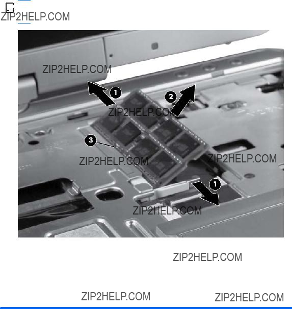
Remove the primary memory module:
1.Spread the retaining tabs (1) on each side of the memory module slot to release the memory module. (The edge of the module opposite the slot rises away from the computer.)

2.Remove the memory module (2) by pulling the module away from the slot at an angle.


 NOTE: Memory modules are designed with a notch (3) to prevent incorrect insertion into the memory module slot.
Reverse this procedure to install a primary memory module.

SIM
 NOTE: This section applies only to computer models with WWAN capability.


 NOTE: If there is a SIM inserted in the SIM slot, it must be removed before disassembling the computer. Be sure that the SIM is reinserted in the SIM slot after reassembling the computer.
Before removing the SIM, follow these steps:
1.Shut down the computer. If you are unsure whether the computer is off or in Hibernation, turn the computer on, and then shut it down through the operating system.
2.Disconnect all external devices connected to the computer.
3.Disconnect the power from the computer by first unplugging the power cord from the AC outlet, and then unplugging the AC adapter from the computer.
4.Remove the following components:
a.Remove the battery (see Battery on page 43)
b.Remove the service access cover (see Service access cover on page 44)
c.Remove the memory module (see Primary memory module on page 45)
Remove the SIM:
1.Press in on the SIM (1). (The module is partially ejected from the SIM slot.)
2.Remove the SIM from the SIM slot.
Reverse this procedure to install the SIM.

Hard drive
 NOTE: The hard drive spare part kits include the bracket and the screws.
Before removing the hard drive, follow these steps:
1.Shut down the computer. If you are unsure whether the computer is off or in Hibernation, turn the computer on, and then shut it down through the operating system.
2.Disconnect all external devices connected to the computer.
3.Disconnect the power from the computer by first unplugging the power cord from the AC outlet, and then unplugging the AC adapter from the computer.
4.Remove the following components:
a.Remove the battery (see Battery on page 43)
b.Remove the service access cover (see Service access cover on page 44)
Remove the hard drive:
1.Loosen the Phillips M2.5??8.0 captive screw (1) that secures the hard drive bracket to the computer.
2.Grasp the tab on the hard drive and slide it forward to disconnect the hard drive.

3.Lift the hard drive (2) to remove it from the computer.
4.If it is necessary to replace the hard drive bracket, remove the four Phillips M2.5x3.0 screws (1) that secure the bracket to the hard drive.
5.Lift the bracket (2) straight up to remove it from the hard drive.
Reverse this procedure to reassemble and install the hard drive.

WLAN module
 CAUTION: The WLAN module and the WWAN module are not interchangeable.
Australia, Austria, Bahrain, Bangladesh, Belarus, Belgium, Benin, Botswana, Brunei, Bulgaria, Burkina Faso, Burundi, Cambodia, Cameroon, Cape Verde, the Central African Republic, Chad, the People's Republic of China, the Congo, Croatia, Cyprus, the Czech Republic, Denmark, Djibouti, Egypt, Equatorial Guinea, Estonia, Finland, France, Gabon, Gambia, Germany, Ghana, Gibraltar, Greece, Guinea,

Brunei, Bulgaria, Burkina Faso, Burundi, Cambodia, Cameroon, Canada, Cape Verde, Cayman Islands, the Central African Republic, Chad, Chile, the People's Republic of China, Colombia, the Congo, Costa Rica, Croatia, Cyprus, the Czech Republic, Denmark, Djibouti, the Dominican Republic, Ecuador, Egypt, El Salvador, Equatorial Guinea, Estonia, Finland, France, French Guiana, Gabon, Gambia, Germany, Ghana, Gibraltar, Greece, Grenada, Guinea, Guadeloupe, Guam. Guatemala,
Before removing the WLAN module, follow these steps:
1.Shut down the computer. If you are unsure whether the computer is off or in Hibernation, turn the computer on, and then shut it down through the operating system.
2.Disconnect all external devices connected to the computer.
3.Disconnect the power from the computer by first unplugging the power cord from the AC outlet, and then unplugging the AC adapter from the computer.
4.Remove the following components:
a.Remove the battery (see Battery on page 43)
b.Remove the service access cover (see Service access cover on page 44)

Remove the WLAN module:
1.Disconnect the WLAN antenna cables (1) from the terminals on the WLAN module and disengage them from the channels (2) holding them in place.


 NOTE: The black WLAN antenna cable is connected to the WLAN module ???Main??? terminal. The white WLAN antenna cable is connected to the WLAN module ???Aux??? terminal.
2.Remove the two Phillips M2.5??3.0 screws (3) that secure the WLAN module to the computer.
3.Remove the WLAN module by pulling the module away from the slot at an angle (4).
 NOTE: WLAN modules are designed with a notch (5) to prevent incorrect insertion.
Reverse this procedure to install the WLAN module.
WWAN module
 CAUTION: The WWAN module and the WLAN module are not interchangeable.
Before removing the WWAN module, follow these steps:
1.Shut down the computer. If you are unsure whether the computer is off or in Hibernation, turn the computer on, and then shut it down through the operating system.
2.Disconnect all external devices connected to the computer.
3.Disconnect the power from the computer by first unplugging the power cord from the AC outlet, and then unplugging the AC adapter from the computer.
4.Remove the following components:
a.Remove the battery (see Battery on page 43)
b.Remove the service access cover (see Service access cover on page 44)
Remove the WWAN module:
1.Disconnect the WWAN antenna cables (1) and (2) from the terminals on the WWAN module.


 NOTE: The red WWAN antenna cable is connected to the WWAN module ???Main??? terminal. The blue WWAN antenna cable is connected to the WWAN module ???Aux??? terminal.
2.Remove the two Phillips M2.5??3.0 screws (3) that secure the WWAN module to the computer. (The edge of the module opposite the slot rises away from the computer.)

3.Remove the WWAN module (4) by pulling the module away from the slot at an angle.
 NOTE: WWAN modules are designed with a notch (5) to prevent incorrect insertion.
Reverse this procedure to install the WWAN module.

Keyboard
Before removing the keyboard, follow these steps:
1.Shut down the computer. If you are unsure whether the computer is off or in Hibernation, turn the computer on, and then shut it down through the operating system.
2.Disconnect all external devices connected to the computer.
3.Disconnect the power from the computer by first unplugging the power cord from the AC outlet, and then unplugging the AC adapter from the computer.
4.Remove the following components:
a.Remove the battery (see Battery on page 43)
b.Remove ths service access cover (see Service access cover on page 44)
Remove the keyboard:
1.Turn the computer

2.Remove the two screw caps (1) and loosen the five captive screws (2) that secure the keyboard to the computer.
3.Turn the computer
4.Open the display as far as possible.
5.Insert a flat tool under the back edge (1) of the keyboard near the display hinge. Gently lift the rear edge of the keyboard (2) and disconnect the keyboard.

6.Holding the keyboard at an angle, lift the keyboard (1) far enough to gain access to the cables underneath and release the zero insertion force (ZIF) connector (2) to which the pointing stick cable is attached to the system board and remove the pointing stick ZIF cable (3) from the connector.
7.Flip the keyboard over to the left and lay it flat (1), then release the ZIF connector that secures the keyboard cable (2) to the system board and remove the keyboard cable (3) from the ZIF connector.

8.Release the ZIF connector to which the pointing stick cable is attached, and then disconnect the cable (4) from the keyboard.
9.Remove the keyboard.
Reverse this procedure to install the keyboard.
Secondary memory module
Update BIOS before adding memory modules
Before adding new memory, make sure you update the computer to the latest BIOS.
 CAUTION: Failure to update the computer to the latest BIOS prior to installing new memory may result in various system problems.
To update BIOS:
1.Navigate to www.hp.com.
2.Click Support & Drivers > click Drivers & Software.
3.In the Enter a product name/number box, type the computer model information, and then click Search.
4.Click the link for the computer model.
5.Select the operating system, and then click Next.
6.Under Step 2: Select a Download, click the BIOS link.
7.Click the link for the most recent BIOS.
8.Click the Download button, and then follow the
Before removing the memory module, follow these steps:
1.Shut down the computer. If you are unsure whether the computer is off or in Hibernation, turn the computer on, and then shut it down through the operating system.
2.Disconnect all external devices connected to the computer.
3.Disconnect the power from the computer by first unplugging the power cord from the AC outlet, and then unplugging the AC adapter from the computer.
4.Remove the following components:
a.Remove the battery (see Battery on page 43)
b.Service access cover (see Service access cover on page 44)
c.Remove the keyboard (see Keyboard on page 55)
Remove the secondary memory module:
1.Spread the retaining tabs (1) on each side of the memory module slot to release the memory module. (The edge of the module opposite the slot rises away from the computer.)
2.Remove the memory module (2) by pulling the module away from the slot at an angle.


 NOTE: Memory modules are designed with a notch (3) to prevent incorrect insertion into the memory module slot.
Reverse this procedure to install a secondary memory module.
Top cover
The top cover kit includes the TouchPad board and capacitive board.
Before removing the top cover, follow these steps:
1.Shut down the computer. If you are unsure whether the computer is off or in Hibernation, turn the computer on, and then shut it down through the operating system.
2.Disconnect all external devices connected to the computer.
3.Disconnect the power from the computer by first unplugging the power cord from the AC outlet, and then unplugging the AC adapter from the computer.
4.Remove the following components:
a.Remove the battery (see Battery on page 43)
b.Remove the service access cover (see Service access cover on page 44)

c.Remove the keyboard (see Keyboard on page 55)
d.Remove the secondary memory module (see Secondary memory module on page 58) Remove the top cover:
1.Turn the computer
2.Remove the two Torx 8M2.0??7.0 screws (1) located in the bottom feet. You do not need to remove the feet.
3.Remove the two screw caps (2) and the two Torx 8M2.0x5.0 screws (3) located below the battery bay.
4.Turn the computer
5.Open the display as far as possible.
6.Release the ZIF connector (1) that secures the audio cable to the system board and remove the audio cable (2) from the ZIF connector.
7.Release the ZIF connector (3) that secures the TouchPad button cable to the system board and remove the touchpad button cable (4) from the ZIF connector.

8.Remove the two Phillips M2.5x7.0 screws (5).
9.Lift the rear edge (1) of the top cover.
10.Disengage the top cover from the computer, and then lift the top cover (2) up and off the computer.
 NOTE: A small plastic brace for the VGA port rests below the top cover. Simply lift the brace.
11.Remove the Phillips M2.0x2.0 screw (1) from the volume control board and slide the volume control (2) out from the tab.
Reverse this procedure to install the top cover.

TouchPad board
 NOTE: The TouchPad board is available with the top cover kit, spare part number
Before removing the TouchPad board, follow these steps:
1.Shut down the computer. If you are unsure whether the computer is off or in Hibernation, turn the computer on, and then shut it down through the operating system.
2.Disconnect all external devices connected to the computer.
3.Disconnect the power from the computer by first unplugging the power cord from the AC outlet, and then unplugging the AC adapter from the computer.
4.Remove the following components:
a.Remove the battery (see Battery on page 43)
b.Remove the service access cover (see Service access cover on page 44)
c.Remove the keyboard (see Keyboard on page 55)
d.Remove the top cover (see Top cover on page 60)
Remove the TouchPad board:
1.Position the computer
2.Remove the Phillips M2.0x3.5 screw (1) that secures the TouchPad to the top cover.
3.Disconnect the TouchPad cable (2) from the TouchPad board ZIF connector and then slide the board (3) out from the tab.
Reverse this procedure to install the TouchPad board.

RTC battery
Before removing the RTC battery, follow these steps:
1.Shut down the computer. If you are unsure whether the computer is off or in Hibernation, turn the computer on, and then shut it down through the operating system.
2.Disconnect all external devices connected to the computer.
3.Disconnect the power from the computer by first unplugging the power cord from the AC outlet, and then unplugging the AC adapter from the computer.
4.Remove the following components:
a.Remove the battery (see Battery on page 43)
b.Remove the service access cover (see Service access cover on page 44)
c.Remove the keyboard (see Keyboard on page 55)
d.Remove the top cover (see Top cover on page 60)
Remove the RTC battery:
1.Disconnect the RTC battery cable (1) from the system board.
2.Gently pull the battery away from the
Reverse this procedure to install the RTC battery.

Display assembly
The display assemblies include two WLAN antenna transceivers and cables and two WWAN antenna transceivers and cables.
Before removing the display assembly, follow these steps:
1.Shut down the computer. If you are unsure whether the computer is off or in Hibernation, turn the computer on, and then shut it down through the operating system.
2.Disconnect all external devices connected to the computer.
3.Disconnect the power from the computer by first unplugging the power cord from the AC outlet, and then unplugging the AC adapter from the computer.
4.Remove the following components:
a.Remove the battery (see Battery on page 43)
b.Remove the service access cover (see Service access cover on page 44)
c.Remove the WLAN module (see WLAN module on page 50)
d.Remove the WWAN module (see WWAN module on page 53)
e.Remove the keyboard (see Keyboard on page 55)
f.Remove the top cover (see Top cover on page 60)
Remove the display assembly:
1.Position the computer upside down, with the rear toward you.

2.Remove the two Torx 9 M2.0??5.0 screws that secure the hinge cover to the computer.
3.Position the computer
4.Slide the hinge cover away from the computer. The hinge cover is available in the Plastics Kit, spare part number
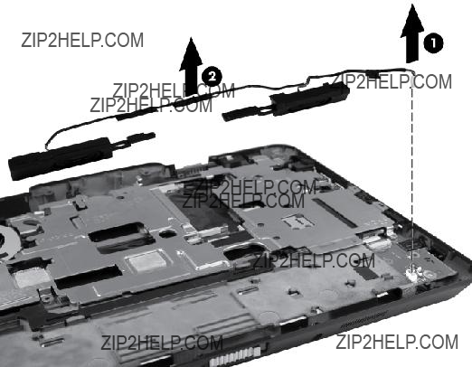
5.Position the computer
6.Feed the WWAN and WLAN antennas (1) through the bottom of the base enclosure and remove the antennas.
7.Disconnect the webcam cable (2) from the system board.

8.Disconnect the display cable (3) from the system board.
 CAUTION: Support the display assembly when removing the display screws in the following step. Failure to support the display assembly can result in damage to the assembly and other components.
9.Remove the two Phillips M2.5x6.0 screws (1) that secure the display assembly to the base enclosure.
10.Gently rotate the display (2) and swivel it at a
11.Remove the two Phillips M2.5 x 6.0 screws (3) that secure the display bracket to the base enclosure.

12. Lift the display straight up to remove it from the base enclosure (4).
Reverse this procedure to reassemble and install the display assembly.
System board shield
Before removing the system board shield, follow these steps:
1.Shut down the computer. If you are unsure whether the computer is off or in Hibernation, turn the computer on, and then shut it down through the operating system.
2.Disconnect all external devices connected to the computer.
3.Disconnect the power from the computer by first unplugging the power cord from the AC outlet, and then unplugging the AC adapter from the computer.
4.Remove the following components:
a.Remove the battery (see Battery on page 43)
b.Remove the service access cover (see Service access cover on page 44)
c.Remove the WLAN module (see WLAN module on page 50)
d.Remove the WWAN module (see WWAN module on page 53)
e.Remove the keyboard (see Keyboard on page 55)

f.Remove the top cover (see Top cover on page 60)
g.Remove the display assembly (see Display assembly on page 66) Remove the system board shield:
1.Position the computer
2.Remove the four Phillips M2.5??3.0 screws (1) and (2) that secure the shield to the base enclosure.
3.Slide the shield from the computer (3).
 WARNING! Use caution when handling the system shield as the object may be hot.
Reverse this procedure to install the system board shield.


 NOTE: When installing a replacement system board shield, take care that the tab labeled ???Watch Out??? is inserted correctly under the heat sink so that the keyboard lies flat when replaced.
Modem module


 NOTE: The modem module spare part kit does not include a modem module cable. The modem module cable is included in the Cable Kit, spare part number

Before removing the modem module, follow these steps:
1.Shut down the computer. If you are unsure whether the computer is off or in Hibernation, turn the computer on, and then shut it down through the operating system.
2.Disconnect all external devices connected to the computer.
3.Disconnect the power from the computer by first unplugging the power cord from the AC outlet, and then unplugging the AC adapter from the computer.
4.Remove the following components:
a.Remove the battery (see Battery on page 43)
b.Remove the service access cover (see Service access cover on page 44)
c.Remove the WLAN module (see WLAN module on page 50)
d.Remove the WWAN module (see WWAN module on page 53)
e.Remove the keyboard (see Keyboard on page 55)
f.Remove the top cover (see Top cover on page 60)
g.Remove the display assembly (see Display assembly on page 66)
h.Remove the system board shield (see System board shield on page 69)
Remove the modem module:
1.Turn the computer
2.Disconnect the modem module (1) from the system board by lifting it straight up.
3.Disconnect the modem module cable (2) from the modem module, and then remove the module from the computer.
Reverse this procedure to install the modem module.

Bluetooth module


 NOTE: The Bluetooth module spare part kit does not include a Bluetooth module cable. The Bluetooth module cable is included in the Cable Kit, spare part number
Before removing the Bluetooth module, follow these steps:
1.Shut down the computer. If you are unsure whether the computer is off or in Hibernation, turn the computer on, and then shut it down through the operating system.
2.Disconnect all external devices connected to the computer.
3.Disconnect the power from the computer by first unplugging the power cord from the AC outlet, and then unplugging the AC adapter from the computer.
4.Remove the following components:
a.Remove the battery (see Battery on page 43)
b.Remove the service access cover (see Service access cover on page 44)
c.Remove the WLAN module (see WLAN module on page 50)
d.Remove the WWAN module (see WWAN module on page 53)
e.Remove the keyboard (see Keyboard on page 55)
f.Remove the top cover (see Top cover on page 60)
g.Remove the display assembly (see Display assembly on page 66)
Remove the Bluetooth module:
1.Position the computer
2.Lift the Bluetooth module (1) as far as the cable will allow.
3.Disconnect the Bluetooth module cable from the Bluetooth module (2) and remove the module.
Reverse this procedure to reassemble and install the Bluetooth module.
Latch assembly
 NOTE: The Latch Kit includes the latch, bracket, two screws, and spring.
Before removing the latch assembly, follow these steps:
1.Shut down the computer. If you are unsure whether the computer is off or in Hibernation, turn the computer on, and then shut it down through the operating system.
2.Disconnect all external devices connected to the computer.
3.Disconnect the power from the computer by first unplugging the power cord from the AC outlet, and then unplugging the AC adapter from the computer.
4.Remove the following components:
a.Remove the battery (see Battery on page 43)
b.Remove the service access cover (see Service access cover on page 44)
c.Remove the WLAN module (see WLAN module on page 50)
d.Remove the WWAN module (see WWAN module on page 53)
e.Remove the keyboard (see Keyboard on page 55)

f.Remove the top cover (see Top cover on page 60)
g.Remove the display assembly (see Display assembly on page 66)
 NOTE: The latch mechanism includes a small spring. Note the location of the spring.
Remove the latch assembly:
1.Position the computer
2.Detach the spring (1) from the latch.
3.Remove the two Phillips M2.0??4.0 screws (2) that secure the latch bracket to the base enclosure.
4.Lift the inner latch (3) from the computer.
Reverse this procedure to install the latch assembly.
Speaker assembly
Before removing the speaker assembly, follow these steps:
1.Shut down the computer. If you are unsure whether the computer is off or in Hibernation, turn the computer on, and then shut it down through the operating system.
2.Disconnect all external devices connected to the computer.
3.Disconnect the power from the computer by first unplugging the power cord from the AC outlet, and then unplugging the AC adapter from the computer.
4.Remove the following components:
a.Remove the battery (see Battery on page 43)
b.Remove the service access cover (see Service access cover on page 44)
c.Remove the WLAN module (see WLAN module on page 50)
d.Remove the WWAN module (see WWAN module on page 53)
e.Remove the keyboard (see Keyboard on page 55)
f.Remove the top cover (see Top cover on page 60)
g.Remove the display assembly (see Display assembly on page 66)
h.Remove the Bluetooth module (see Bluetooth module on page 72)
i.Latch assembly (see Latch assembly on page 73)
Remove the speaker assembly:
1.Position the computer
2.Unplug the speaker cable (1) from the audio connector board, and note the routing channel of the speaker cable in the base enclosure.
3.Slide the the speakers and cables (2) from the base enclosure and lift to remove.
Reverse this procedure to install the speaker assembly.

Audio board
Before removing the audio connector board, follow these steps:
1.Shut down the computer. If you are unsure whether the computer is off or in Hibernation, turn the computer on, and then shut it down through the operating system.
2.Disconnect all external devices connected to the computer.
3.Disconnect the power from the computer by first unplugging the power cord from the AC outlet, and then unplugging the AC adapter from the computer.
4.Remove the following components:
a.Remove the battery (see Battery on page 43)
b.Remove the service access cover (see Service access cover on page 44)
c.Remove the WLAN module (see WLAN module on page 50)
d.Remove the WWAN module (see WWAN module on page 53)
e.Remove the keyboard (see Keyboard on page 55)
f.Remove the top cover (see Top cover on page 60)
g.Remove the display assembly (see Display assembly on page 66)
h.Remove the Bluetooth module (see Bluetooth module on page 72)
i.Latch assembly (see Latch assembly on page 73)
j.Remove the speaker assembly (see Speaker assembly on page 74)
Remove the audio connector board:
1.Position the computer
2.Release the ZIF connector (1) that secures the audio board cable to the system board and remove the audio board cable (2).

3.Remove the Phillips M2.0??3.5 screw (3) that secures the audio connector board to the base enclosure and lift the board (4).
Reverse this procedure to install the audio connector board.

Smart card reader
Before removing the smart card reader, follow these steps:
1.Shut down the computer. If you are unsure whether the computer is off or in Hibernation, turn the computer on, and then shut it down through the operating system.
2.Disconnect all external devices connected to the computer.
3.Disconnect the power from the computer by first unplugging the power cord from the AC outlet, and then unplugging the AC adapter from the computer.
4.Remove the following components:
a.Remove the battery (see Battery on page 43)
b.Remove the service access cover (see Service access cover on page 44)
c.Remove the WLAN module (see WLAN module on page 50)
d.Remove the WWAN module (see WWAN module on page 53)
e.Remove the keyboard (see Keyboard on page 55)
f.Remove the top cover (see Top cover on page 60)
g.Remove the display assembly (see Display assembly on page 66)
h.System board shield (see System board shield on page 69)
Remove the smart card reader:
1.Position the computer
2.Disconnect the smart card reader cable from the ZIF connector (1) on the system board and remove the cable (2).

3.Lift the smart card reader out of the chassis (3).


 NOTE: Adhesive secures the reader to the base enclosure. You must break the adhesion to remove the reader.
4.Remove the Bluetooth cable by disconnecting the ZIF cable (1) securing the Bluetooth module to the system board and thn lift the cable (2).
Reverse this procedure to install the smart card reader.

System board
 NOTE: The system board spare part kits include replacement thermal material.
Before removing the system board, follow these steps:
1.Shut down the computer. If you are unsure whether the computer is off or in Hibernation, turn the computer on, and then shut it down through the operating system.
2.Disconnect all external devices connected to the computer.
3.Disconnect the power from the computer by first unplugging the power cord from the AC outlet, and then unplugging the AC adapter from the computer.
4.Remove the following components:
a.Remove the battery (see Battery on page 43)
b.Remove the service access cover (see Service access cover on page 44)
c.Remove the SIM card (see SIM on page 47)
d.Remove the memory module (see Primary memory module on page 45)
e.Remove the hard drive (see Hard drive on page 48)
f.Remove the WLAN module (see WLAN module on page 50)
g.Remove the WWAN module (see WWAN module on page 53)
h.Remove the keyboard (see Keyboard on page 55)
i.Remove the top cover (see Top cover on page 60)

j.Remove the RTC battery (see RTC battery on page 65)
k.Remove the display assembly (see Display assembly on page 66)
l.Remove the system board shield (see System board shield on page 69)
m.Remove the smart card reader (see Smart card reader on page 78)
When replacing the system board, be sure that the following components are removed from the defective system board and installed on the replacement system board:
???Remove the SIM (see SIM on page 47)
???Remove the memory modules (see Primary memory module on page 45 and Secondary memory module on page 58)
???Remove the WLAN module (see WLAN module on page 50)
???Remove the WWAN module (see WWAN module on page 53)
???Remove the modem module (see Modem module on page 70)
???Remove the heat sink (see Fan/heat sink assembly on page 82)
Remove the system board:
1.Position the computer
2.Remove the ExpressCard or ExpressCard slot holder.
3.Peel back the adhesive strip (2) on the system board to reveal one of the two screws required to remove the system board.
4.Remove the two Phillips M2.0??4.0 screws (2) that secure the system board to the base enclosure.

5.Lift the right side of the system board, and remove it from the base enclosure (3).
Reverse this procedure to install the system board.
Fan/heat sink assembly
The heat sink spare part kit includes replacement thermal material.
Before removing the fan/heat sink assembly, follow these steps:
1.Shut down the computer. If you are unsure whether the computer is off or in Hibernation, turn the computer on, and then shut it down through the operating system.
2.Disconnect all external devices connected to the computer.
3.Disconnect the power from the computer by first unplugging the power cord from the AC outlet, and then unplugging the AC adapter from the computer.
4.Remove the following components:
a.Remove the battery (see Battery on page 43)
b.Remove the service access cover (see Service access cover on page 44)
c.Remove the SIM card (see SIM on page 47)
d.Remove the memory module (see Primary memory module on page 45)
e.Remove the hard drive (see Hard drive on page 48)
f.Remove the WLAN module (see WLAN module on page 50)
g.Remove the WWAN module (see WWAN module on page 53)
h.Remove the keyboard (see Keyboard on page 55)
i.Remove the top cover (see Top cover on page 60)
j.Remove the RTC battery (see RTC battery on page 65)
k.Remove the display assembly (see Display assembly on page 66)
l.Remove the system board shield (see System board shield on page 69)
m.Remove the smart card reader (see Smart card reader on page 78)
n.Remove the system board (see System board on page 80)
Remove the fan/heat sink assembly:
1.Position the system board right side up.
2.Disconnect the fan cable from the system board.
3.Position the system board upside down.
4.In the order indicated on the heat sink, loosen the four Phillips captive screws (1) that secure the heat sink to the base enclosure.
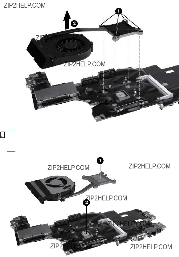
5.Remove the fan/heat sink assembly (2).


 NOTE: The thermal material must be thoroughly cleaned from the surfaces of the heat sink (1) and processor (2) each time the heat sink is removed. Thermal material is included with fan/heat sink assembly and system board spare part kits.
Reverse this procedure to install the fan/heat sink assembly.

5 Computer Setup
Starting Computer Setup
Computer Setup is a preinstalled,


 NOTE: Some of the Computer Setup menu items listed in this guide may not be supported by your computer.


 NOTE: An external keyboard or mouse connected to a USB port can be used with Computer Setup only if USB legacy support is enabled.
To start Computer Setup, follow these steps:
1.Turn on or restart the computer, and then press esc while the ???Press the ESC key for Startup Menu??? message is displayed at the bottom of the screen.
2.Press f10 to enter BIOS Setup.
Using Computer Setup
Navigating and selecting in Computer Setup
The information and settings in Computer Setup are accessed from the File, Security, and System Configuration menus.
To navigate and select in Computer Setup, follow these steps:
1.Turn on or restart the computer, and then press esc while the ???Press the ESC key for Startup Menu??? message is displayed at the bottom of the screen.
???To select a menu or a menu item, use the tab key and the keyboard arrow keys, and then press enter, or use a pointing device to click the item.
???To scroll up and down, click the up arrow or the down arrow on the right side of the screen, or use the up arrow key or the down arrow key.
???To close open dialog boxes and return to the main Computer Setup screen, press esc, and then follow the


 NOTE: You can use either a pointing device (TouchPad, pointing stick, or USB mouse) or the keyboard to navigate and make selections in Computer Setup.
2.Press f10 to enter BIOS Setup.
3.Select the File, Security, or System Configuration menu.

To exit Computer Setup menus, choose one of the following methods:
???To exit Computer Setup menus without saving your changes, click the Exit icon in the
??? or ???
Use the tab key and the arrow keys to select File > Ignore Changes and Exit, and then press enter.
??? or ???
???To save your changes and exit Computer Setup menus, click the Save icon in the
??? or ???
Use the tab key and the arrow keys to select File > Save Changes and Exit, and then press enter.
Your changes go into effect when the computer restarts.
Restoring factory settings in Computer Setup
 NOTE: Restoring defaults will not change the hard drive mode.
To return all settings in Computer Setup to the values that were set at the factory, follow these steps:
1.Turn on or restart the computer, and then press esc while the ???Press the ESC key for Startup Menu??? message is displayed at the bottom of the screen.
2.Press f10 to enter BIOS Setup.
3.Use a pointing device or the arrow keys to select File > Restore Defaults.
4.Follow the
5.To save your changes and exit, click the Save icon in the
??? or ???
Use the arrow keys to select File > Save Changes and Exit, and then press enter. Your changes go into effect when the computer restarts.
NOTE: Your password settings and security settings are not changed when you restore the factory settings.
86 Chapter 5 Computer Setup

Computer Setup menus
The menu tables in this section provide an overview of Computer Setup options.


 NOTE: Some of the Computer Setup menu items listed in this chapter may not be supported by your computer.
File menu

Security menu
 NOTE: Some of the menu items listed in this section may not be supported by your computer.
88 Chapter 5 Computer Setup


System Configuration menu
 NOTE: Some of the listed System Configuration options may not be supported by your computer.
90 Chapter 5 Computer Setup

NOTE: Availability of these options varies by computer model.
??? Enable/disable secondary battery fast charge (enabled by default).
??? Enable/disable HP QuickLook (enabled by default).
??? Enable/disable preboot authentication on HP QuickLook boot (enabled by default).
??? Enable/disable HP QuickWeb (enabled by default).
??? Enable/disable HP QuickWeb write protect (disabled by default).
??? Enable/disable virtualization technology (select models only; disabled by default).
??? Enable/disable TXT (Intel Trusted Execution Technology) (select models only; disabled by default).
??? Enable/disable Multi Core CPU (enabled by default).
???
???
??? Enable/disable Num lock state at boot (disabled by default).

??? Enable/disable the flash media reader.
???
??? Enable/disable the 1394 port.
???
???
???
92 Chapter 5 Computer Setup

6 Specifications
Computer specifications
NOTE: Applicable product safety standards specify thermal limits for plastic surfaces. The computer operates well within this range of temperatures.
94 Chapter 6 Specifications

Hard drive specifications
Seek times (typical read, including setting)

*1 GB = 1 billion bytes when referring to hard drive storage capacity. Actual accessible capacity is less. Actual drive specifications may differ slightly.
NOTE: Certain restrictions and exclusions apply. Contact technical support for details.
96 Chapter 6 Specifications

7 Backup and recovery
To protect your information, use Windows Backup and Restore to back up individual files and folders, back up your entire hard drive (select models only), create system repair discs (select models only), or create system restore points. In case of system failure, you can use the backup files to restore the contents of your computer.
Windows Backup and Restore provides the following options:
???Creating a system repair disc (select models only)
???Backing up individual files and folders
???Creating a system image (select models only)
???Scheduling automatic backups (select models only)
???Creating system restore points
???Recovering individual files
???Restoring the computer to a previous state
???Recovering information using recovery tools
 NOTE: For detailed instructions, perform a search for these topics in Help and Support.


 NOTE: In case of system instability, HP recommends that you print the recovery procedures and save them for later use.
Backing up your information
Recovery after a system failure is as complete as your most current backup. You should create system repair discs (select models only) and your initial backup immediately after software setup. As you add new software and data files, you should continue to back up your system on a regular basis to maintain a reasonably current backup. The system repair discs (select models only) are used to start up (boot) the computer and repair the operating system in case of system instability or failure. Your initial and subsequent backups allow you to restore your data and settings if a failure occurs.
You can back up your information to an optional external hard drive, a network drive, or discs. Note the following when backing up:
???Store personal files in the Documents library, and back it up regularly.
???Back up templates that are stored in their associated programs.
???Save customized settings that appear in a window, toolbar, or menu bar by taking a screen shot of your settings. The screen shot can be a

To create a screen shot:
1.Display the screen you want to save.
2.Copy the screen image:
To copy only the active window, press alt+fn+prt. To copy the entire screen, press fn+prt sc.
3.Open a
4.Save the document.
???When backing up to discs, use any of the following types of discs (purchased separately):


 NOTE: DVDs and DVDs with
???When backing up to discs, number each disc before inserting it into the optical drive of the computer.
To create a backup using Backup and Restore, follow these steps:
 NOTE: Be sure that the computer is connected to AC power before you start the backup process.


 NOTE: The backup process may take over an hour, depending on file size and the speed of the computer.
1.Select Start > All Programs > Maintenance > Backup and Restore.
2.Follow the


 NOTE: Windows includes the User Account Control feature to improve the security of your computer. You may be prompted for your permission or password for tasks such as installing software, running utilities, or changing Windows settings. Refer to Help and Support for more information.
Performing a recovery
In case of system failure or instability, the computer provides the following tools to recover your files:
???Windows recovery tools: You can use Windows Backup and Restore to recover information you have previously backed up. You can also use Windows Startup Repair to fix problems that might prevent Windows from starting correctly.
???f11 recovery tools: You can use the f11 recovery tools to recover your original hard drive image. The image includes the Windows operating system and software programs installed at the factory.


 NOTE: If you are unable to boot (start up) your computer and you cannot use the system repair discs you previously created (select models only), you must purchase a Windows 7 operating system DVD to reboot the computer and repair the operating system. For additional information, refer to the ???Using a Windows 7 operating system DVD (purchased separately)??? section in this guide.
Using the Windows recovery tools
To recover information you previously backed up, follow these steps:
1.Select Start > All Programs > Maintenance > Backup and Restore.
2.Follow the


 NOTE: Windows includes the User Account Control feature to improve the security of your computer. You may be prompted for your permission or password for tasks such as installing software, running utilities, or changing Windows settings. Refer to Help and Support for more information.
To recover your information using Startup Repair, follow these steps:
 CAUTION: Using Startup Repair completely erases hard drive contents and reformats the hard drive. All files you have created and any software installed on the computer are permanently removed. When reformatting is complete, the recovery process restores the operating system, as well as the drivers, software, and utilities, from the backup used for recovery.
1.If possible, back up all personal files.
2.If possible, check for the presence of the Windows partition and the HP Recovery partition. To check for the Windows partition, select Start > Computer.
To check for the HP Recovery partition, select Start,


 NOTE: If the Windows partition and the HP Recovery partition are not listed, you must recover your operating system and programs using the Windows 7 operating system DVD and the Driver Recovery disc (both purchased separately). For additional information, refer to the ???Using a Windows 7 operating system DVD (purchased separately)??? section in this guide.
3.If the Windows partition and the HP Recovery partition are listed, restart the computer, and then press f8 before the Windows operating system loads.
4.On the Advanced Boot Options screen, use the arrow keys to highlight Repair your computer, and then press enter.
5.Follow the


 NOTE: For additional information on recovering information using the Windows tools, perform a search for these topics in Help and Support.

Using f11
 CAUTION: Using f11 completely erases hard drive contents and reformats the hard drive. All files you have created and any software installed on the computer are permanently removed. The f11 recovery tool reinstalls the operating system and HP programs and drivers that were installed at the factory. Software not installed at the factory must be reinstalled.
To recover the original hard drive image using f11, follow these steps:
1.If possible, back up all personal files.
2.If possible, check for the presence of the HP Recovery partition: select Start,
Computer, click Manage, and then click Disk Management.


 NOTE: If the HP Recovery partition is not listed, you must recover your operating system and programs using the Windows 7 operating system DVD and the Driver Recovery disc (both purchased separately). For additional information, refer to the ???Using a Windows 7 operating system DVD (purchased separately)??? section in this guide.
3.If the HP Recovery partition is listed, restart the computer, and then press esc while the ???Press the ESC key for Startup Menu??? message is displayed at the bottom of the screen.
4.Press f11 to enter the HP Recovery menu.
5.Follow the
Using a Windows 7 operating system DVD (purchased separately)
If you are unable to boot (start up) your computer and you cannot use the system repair discs you previously created (select models only), you must purchase a Windows 7 operating system DVD to reboot the computer and repair the operating system. Make sure that your most recent backup (stored on discs or on an external drive) is easily accessible. To order a Windows 7 operating system DVD, go to http://www.hp.com/support, select your country or region, and then follow the
 CAUTION: Using a Windows 7 operating system DVD completely erases hard drive contents and reformats the hard drive. All files you have created and any software installed on the computer are permanently removed. When reformatting is complete, the recovery process helps you restore the operating system, as well as drivers, software, and utilities.
To initiate recovery using a Windows 7 operating system DVD, follow these steps:
 NOTE: This process takes several minutes.
1.If possible, back up all personal files.
2.Restart the computer, and then insert the Windows 7 operating system DVD into the optical drive before the Windows operating system loads.
3.When prompted, press any keyboard key.
4.Follow the
5.Click Next.
100 Chapter 7 Backup and recovery
6.Select Repair your computer.
7.Follow the
Performing a recovery 101

8 Power cord set requirements
The wide range input feature of the computer permits it to operate from any line voltage from 100 to 120 volts AC, or from 220 to 240 volts AC.
The
Power cord sets for use in other countries and regions must meet the requirements of the country or region where the computer is used.
Requirements for all countries and regions
The requirements listed below are applicable to all countries and regions:
???The length of the power cord set must be at least 1.5 m (5.0 ft) and no more than 2.0 m (6.5 ft).
???All power cord sets must be approved by an acceptable accredited agency responsible for evaluation in the country or region where the power cord set will be used.
???The power cord sets must have a minimum current capacity of 10 amps and a nominal voltage rating of 125 or 250 V AC, as required by the power system of each country or region.
???The appliance coupler must meet the mechanical configuration of an EN 60 320/IEC 320 Standard Sheet C13 connector for mating with the appliance inlet on the back of the computer.
Requirements for specific countries and regions
102 Chapter 8 Power cord set requirements
1.The flexible cord must be Type
2.The flexible cord must be Type
3.The appliance coupler, flexible cord, and wall plug must bear a ???T??? mark and registration number in accordance with the Japanese Dentori Law. The flexible cord must be Type VCT or VCTF,
4.The flexible cord must be Type RVV,
5.The flexible cord must be Type VCTF,

9 Recycling
Battery
When a battery has reached the end of its useful life, do not dispose of the battery in general household waste. Follow the local laws and regulations in your area for computer battery disposal.
Display
WARNING! The backlight contains mercury. Caution must be exercised when removing and handling the backlight to avoid damaging this component and causing exposure to the mercury.
CAUTION: The procedures in this chapter can result in damage to display components. The only components intended for recycling purposes are the liquid crystal display (LCD) panel and the backlight. When you remove these components, handle them carefully.


 NOTE: Materials Disposal. This HP product contains mercury in the backlight in the display assembly that might require special handling at
This section provides disassembly instructions for the display assembly. The display assembly must be disassembled to gain access to the backlight (1) and the liquid crystal display (LCD) panel (2).


 NOTE: The procedures provided in this chapter are general disassembly instructions. Specific details, such as screw sizes, quantities, and locations, and component shapes and sizes, can vary from one computer model to another.
104 Chapter 9 Recycling

Perform the following steps:
1.Remove the (1) and screws (2) that secure the display bezel to the display assembly.
2.Lift up and out on the left and right inside edges (1) and the top and bottom inside edges (2) of the display bezel until the bezel disengages from the display assembly.
3.Remove the display bezel 3.
Display 105

4.Disconnect all display panel cables (1) from the display inverter and remove the inverter 2.
5.Remove all screws (1) that secure the display panel assembly to the display enclosure.
6.Remove the display panel assembly (2) from the display enclosure.
7.Turn the display panel assembly upside down.
8.Remove all screws that secure the display panel frame to the display panel.
9.Use a
106 Chapter 9 Recycling
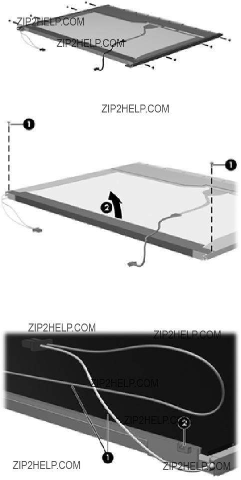
10. Remove the display panel frame (2) from the display panel.
11.Remove the screws (1) that secure the backlight cover to the display panel.
12.Lift the top edge of the backlight cover (2) and swing it outward.
13.Remove the backlight cover.
14.Turn the display panel
15.Remove the backlight cables (1) from the clip (2) in the display panel.
16. Turn the display panel upside down.
Display 107

17. Remove the backlight frame from the display panel.
 WARNING! The backlight contains mercury. Exercise caution when removing and handling the backlight to avoid damaging this component and causing exposure to the mercury.
18. Remove the backlight from the backlight frame.
19.Disconnect the display cable (1) from the LCD panel.
20.Remove the screws (2) that secure the LCD panel to the display rear panel.
21.Release the LCD panel (3) from the display rear panel.
108 Chapter 9 Recycling

22. Release the tape (4) that secures the LCD panel to the display rear panel.
23. Remove the LCD panel.
24. Recycle the LCD panel and backlight.
Display 109

ExpressCard slot insert, illustrated 24
external media cards, product
G
graphics, product description 1 grounding equipment and
methods 39
internal microphones, identifying
identifying 14
keypad, embedded numeric 10
function 10
Windows applications 10 Windows logo 10
L
language, changing in Computer
volume down 7 volume up 7 webcam 14
M
mass storage devices, spare part numbers 26
Media Card Reader, identifying
microphone
microphone, product description
N
network jack, identifying 16 num lock light 7
O
operating system, product description 4
P
packing guidelines 38
Index 111