ProCurve Switches
Access Security Guide
Switch 2600 Series
Switch
Switch 2800 Series
Switch 4100 Series
Switch 6108 Series
ProCurve Switches
Access Security Guide
Switch 2600 Series
Switch
Switch 2800 Series
Switch 4100 Series
Switch 6108 Series

ProCurve
Switch 2600 Series
Switch
Switch 2800 Series
Switch 4100gl Series
Switch 6108
December 2008
Access Security Guide

?? Copyright
The information contained herein is subject to change without notice.
Publication Number
Applicable Products
Trademark Credits
Windows NT??, Windows??, and MS Windows?? are US registered trademarks of Microsoft Corporation.
Software Credits
SSH on ProCurve Switches is based on the OpenSSH software toolkit. This product includes software developed by the OpenSSH Project for use in the OpenSSH Toolkit. For more information on OpenSSH, visit http:// www.openssh.com.
SSL on ProCurve Switches is based on the OpenSSL software toolkit. This product includes software developed by the OpenSSL Project for use in the OpenSSL Toolkit. For more information on OpenSSL, visit
http://www.openssl.org.
This product includes cryptographic software written by Eric Young (eay@cryptsoft.com)
This product includes software written by Tim Hudson (tjh@cryptsoft.com)
Disclaimer
OF ANY KIND WITH REGARD TO THIS MATERIAL,
INCLUDING, BUT NOT LIMITED TO, THE IMPLIED
WARRANTIES OF MERCHANTABILITY AND FITNESS FOR A PARTICULAR PURPOSE.
Warranty
See the Customer Support/Warranty booklet included with the product.
A copy of the specific warranty terms applicable to your
8000 Foothills Boulevard, m/s 5551 Roseville, California
http://www.procurve.com

Contents
Product Documentation
About Your Switch Manual Set . . . . . . . . . . . . . . . . . . . . . . . . . . . . . . . . . . . . . xi Feature Index . . . . . . . . . . . . . . . . . . . . . . . . . . . . . . . . . . . . . . . . . . . . . . . . . . .xii
1 Getting Started
Contents . . . . . . . . . . . . . . . . . . . . . . . . . . . . . . . . . . . . . . . . . . . . . . . . . . . . . . .
2 Configuring Username and Password Security
Contents . . . . . . . . . . . . . . . . . . . . . . . . . . . . . . . . . . . . . . . . . . . . . . . . . . . . . . .
Overview . . . . . . . . . . . . . . . . . . . . . . . . . . . . . . . . . . . . . . . . . . . . . . . . . . . . . .
Configuring Local Password Security . . . . . . . . . . . . . . . . . . . . . . . . . . . . . .
Menu: Setting Passwords . . . . . . . . . . . . . . . . . . . . . . . . . . . . . . . . . . . . .
CLI: Setting Passwords and Usernames . . . . . . . . . . . . . . . . . . . . . . . . .
Web: Setting Passwords and Usernames . . . . . . . . . . . . . . . . . . . . . . . .
iii

When Security Is Important . . . . . . . . . . . . . . . . . . . . . . . . . . . . . . . . . . .
Configuring
Password Recovery . . . . . . . . . . . . . . . . . . . . . . . . . . . . . . . . . . . . . . . . .
Password Recovery Process . . . . . . . . . . . . . . . . . . . . . . . . . . . . . . . . .
3Web and MAC Authentication for the Series 2600/
Contents . . . . . . . . . . . . . . . . . . . . . . . . . . . . . . . . . . . . . . . . . . . . . . . . . . . . . . .
Overview . . . . . . . . . . . . . . . . . . . . . . . . . . . . . . . . . . . . . . . . . . . . . . . . . . . . . .
Client Options . . . . . . . . . . . . . . . . . . . . . . . . . . . . . . . . . . . . . . . . . . . . . .
General Features . . . . . . . . . . . . . . . . . . . . . . . . . . . . . . . . . . . . . . . . . . . .
How Web and MAC Authentication Operate . . . . . . . . . . . . . . . . . . . . . . . .
Authenticator Operation . . . . . . . . . . . . . . . . . . . . . . . . . . . . . . . . . . . . .
Terminology . . . . . . . . . . . . . . . . . . . . . . . . . . . . . . . . . . . . . . . . . . . . . . . . . . .
Operating Rules and Notes . . . . . . . . . . . . . . . . . . . . . . . . . . . . . . . . . . . . . .
General Setup Procedure for Web/MAC Authentication . . . . . . . . . . . . . .
Additional Information for Configuring the RADIUS Server To Support MAC Authentication . . . . . . . . . . . . . . . . . . . . . . . . . . . . . . . . . . . . . . . .
Configuring the Switch To Access a RADIUS Server . . . . . . . . . . . . . . . .
Configuring Web Authentication . . . . . . . . . . . . . . . . . . . . . . . . . . . . . . . . .
Configuring MAC Authentication on the Switch . . . . . . . . . . . . . . . . . . . .
Show Status and Configuration of
Show Status and Configuration of
Show Client Status . . . . . . . . . . . . . . . . . . . . . . . . . . . . . . . . . . . . . . . . . . . . .
iv

4 TACACS+ Authentication
Contents . . . . . . . . . . . . . . . . . . . . . . . . . . . . . . . . . . . . . . . . . . . . . . . . . . . . . . .
Overview . . . . . . . . . . . . . . . . . . . . . . . . . . . . . . . . . . . . . . . . . . . . . . . . . . . . . .
Terminology Used in TACACS Applications: . . . . . . . . . . . . . . . . . . . . . . . .
General System Requirements . . . . . . . . . . . . . . . . . . . . . . . . . . . . . . . . . . . .
General Authentication Setup Procedure . . . . . . . . . . . . . . . . . . . . . . . . . . .
Controlling Web Browser Interface Access When Using TACACS+
Authentication . . . . . . . . . . . . . . . . . . . . . . . . . . . . . . . . . . . . . . . . . . . . . . . .
Messages Related to TACACS+ Operation . . . . . . . . . . . . . . . . . . . . . . . . .
Operating Notes . . . . . . . . . . . . . . . . . . . . . . . . . . . . . . . . . . . . . . . . . . . . . . .
5 RADIUS Authentication and Accounting
Contents . . . . . . . . . . . . . . . . . . . . . . . . . . . . . . . . . . . . . . . . . . . . . . . . . . . . . . .
Overview . . . . . . . . . . . . . . . . . . . . . . . . . . . . . . . . . . . . . . . . . . . . . . . . . . . . . .
Terminology . . . . . . . . . . . . . . . . . . . . . . . . . . . . . . . . . . . . . . . . . . . . . . . . . . .
Switch Operating Rules for RADIUS . . . . . . . . . . . . . . . . . . . . . . . . . . . . . . .
General RADIUS Setup Procedure . . . . . . . . . . . . . . . . . . . . . . . . . . . . . . . . .
Configuring the Switch for RADIUS Authentication . . . . . . . . . . . . . . . . . .
v

1. Configure Authentication for the Access Methods You Want RADIUS
Local Authentication Process . . . . . . . . . . . . . . . . . . . . . . . . . . . . . . . . . . . .
Controlling Web Browser Interface Access When Using RADIUS
Authentication . . . . . . . . . . . . . . . . . . . . . . . . . . . . . . . . . . . . . . . . . . . . . . . .
Configuring RADIUS Accounting . . . . . . . . . . . . . . . . . . . . . . . . . . . . . . . . .
Viewing RADIUS Statistics . . . . . . . . . . . . . . . . . . . . . . . . . . . . . . . . . . . . . .
General RADIUS Statistics . . . . . . . . . . . . . . . . . . . . . . . . . . . . . . . . . . .
RADIUS Authentication Statistics . . . . . . . . . . . . . . . . . . . . . . . . . . . . .
RADIUS Accounting Statistics . . . . . . . . . . . . . . . . . . . . . . . . . . . . . . . .
Changing
Messages Related to RADIUS Operation . . . . . . . . . . . . . . . . . . . . . . . . . . .
6 Configuring Secure Shell (SSH)
Contents . . . . . . . . . . . . . . . . . . . . . . . . . . . . . . . . . . . . . . . . . . . . . . . . . . . . . . .
Overview . . . . . . . . . . . . . . . . . . . . . . . . . . . . . . . . . . . . . . . . . . . . . . . . . . . . . .
Terminology . . . . . . . . . . . . . . . . . . . . . . . . . . . . . . . . . . . . . . . . . . . . . . . . . . .
Prerequisite for Using SSH . . . . . . . . . . . . . . . . . . . . . . . . . . . . . . . . . . . . . . .
Public Key Formats . . . . . . . . . . . . . . . . . . . . . . . . . . . . . . . . . . . . . . . . . . . . .
Steps for Configuring and Using SSH for Switch and Client Authentication .
General Operating Rules and Notes . . . . . . . . . . . . . . . . . . . . . . . . . . . . . . . .
Configuring the Switch for SSH Operation . . . . . . . . . . . . . . . . . . . . . . . . . .
4. Enable SSH on the Switch and Anticipate SSH Client Contact Behavior
5. Configure the Switch for SSH Authentication . . . . . . . . . . . . . . . . .
vi

6. Use an SSH Client To Access the Switch . . . . . . . . . . . . . . . . . . . . .
Further Information on SSH Client
Messages Related to SSH Operation . . . . . . . . . . . . . . . . . . . . . . . . . . . . . .
7 Configuring Secure Socket Layer (SSL)
Contents . . . . . . . . . . . . . . . . . . . . . . . . . . . . . . . . . . . . . . . . . . . . . . . . . . . . . . .
Overview . . . . . . . . . . . . . . . . . . . . . . . . . . . . . . . . . . . . . . . . . . . . . . . . . . . . . .
Terminology . . . . . . . . . . . . . . . . . . . . . . . . . . . . . . . . . . . . . . . . . . . . . . . . . . .
Prerequisite for Using SSL . . . . . . . . . . . . . . . . . . . . . . . . . . . . . . . . . . . . . . . .
Steps for Configuring and Using SSL for Switch and Client Authentication .
General Operating Rules and Notes . . . . . . . . . . . . . . . . . . . . . . . . . . . . . . . .
Configuring the Switch for SSL Operation . . . . . . . . . . . . . . . . . . . . . . . . . .
3. Enable SSL on the Switch and Anticipate SSL Browser Contact Behavior . . . . . . . . . . . . . . . . . . . . . . . . . . . . . . . . . . . . . . . . . . . . . . . . . .
Common Errors in SSL Setup . . . . . . . . . . . . . . . . . . . . . . . . . . . . . . . . . . . .
8 Configuring
Contents . . . . . . . . . . . . . . . . . . . . . . . . . . . . . . . . . . . . . . . . . . . . . . . . . . . . . . .
Overview . . . . . . . . . . . . . . . . . . . . . . . . . . . . . . . . . . . . . . . . . . . . . . . . . . . . . .
Why Use
General Features . . . . . . . . . . . . . . . . . . . . . . . . . . . . . . . . . . . . . . . . . . . .
How 802.1X Operates . . . . . . . . . . . . . . . . . . . . . . . . . . . . . . . . . . . . . . . . . . . .
Authenticator Operation . . . . . . . . . . . . . . . . . . . . . . . . . . . . . . . . . . . . .
Terminology . . . . . . . . . . . . . . . . . . . . . . . . . . . . . . . . . . . . . . . . . . . . . . . . . . .
General Operating Rules and Notes . . . . . . . . . . . . . . . . . . . . . . . . . . . . . . .
General Setup Procedure for
vii

Configuring Switch Ports as 802.1X Authenticators . . . . . . . . . . . . . . . . .
Option For Authenticator Ports: Configure
Configuring Switch Ports To Operate As Supplicants for 802.1X Connections to Other Switches . . . . . . . . . . . . . . . . . . . . . . . . . . . . . . . . . . . . . . . . . . . . . .
Displaying 802.1X Configuration, Statistics, and Counters . . . . . . . . . . . .
How RADIUS/802.1X Authentication Affects VLAN Operation . . . . . . . .
Messages Related to 802.1X Operation . . . . . . . . . . . . . . . . . . . . . . . . . . . .
9 Configuring and Monitoring Port Security
Contents . . . . . . . . . . . . . . . . . . . . . . . . . . . . . . . . . . . . . . . . . . . . . . . . . . . . . . .
Overview . . . . . . . . . . . . . . . . . . . . . . . . . . . . . . . . . . . . . . . . . . . . . . . . . . . . . .
Basic Operation . . . . . . . . . . . . . . . . . . . . . . . . . . . . . . . . . . . . . . . . . . . . .
Blocking Unauthorized Traffic . . . . . . . . . . . . . . . . . . . . . . . . . . . . . . . .
Trunk Group Exclusion . . . . . . . . . . . . . . . . . . . . . . . . . . . . . . . . . . . . . .
Planning Port Security . . . . . . . . . . . . . . . . . . . . . . . . . . . . . . . . . . . . . . . . . . .
Port Security Command Options and Operation . . . . . . . . . . . . . . . . . . . . .
viii
MAC Lockdown . . . . . . . . . . . . . . . . . . . . . . . . . . . . . . . . . . . . . . . . . . . . . . .
Differences Between MAC Lockdown and Port Security . . . . . . . . .
Deploying MAC Lockdown . . . . . . . . . . . . . . . . . . . . . . . . . . . . . . . . . .
MAC Lockout . . . . . . . . . . . . . . . . . . . . . . . . . . . . . . . . . . . . . . . . . . . . . . . . .
Port Security and MAC Lockout . . . . . . . . . . . . . . . . . . . . . . . . . . . . . .
IP Lockdown . . . . . . . . . . . . . . . . . . . . . . . . . . . . . . . . . . . . . . . . . . . . . . . . . .
Web: Displaying and Configuring Port Security Features . . . . . . . . . . . . .
Reading Intrusion Alerts and Resetting Alert Flags . . . . . . . . . . . . . . . . . .
Web: Checking for Intrusions, Listing Intrusion Alerts, and Resetting Alert Flags . . . . . . . . . . . . . . . . . . . . . . . . . . . . . . . . . . . . . . . . . . . . . . . .
Operating Notes for Port Security . . . . . . . . . . . . . . . . . . . . . . . . . . . . . . . .
10Traffic/Security Filters
(ProCurve Series
Contents . . . . . . . . . . . . . . . . . . . . . . . . . . . . . . . . . . . . . . . . . . . . . . . . . . . . . .
Overview . . . . . . . . . . . . . . . . . . . . . . . . . . . . . . . . . . . . . . . . . . . . . . . . . . . . .
Using
Operating Rules for
Configuring a
Viewing a
Filter Indexing . . . . . . . . . . . . . . . . . . . . . . . . . . . . . . . . . . . . . . . . . . . . .
Editing a
Using Named
11 Using Authorized IP Managers
Contents . . . . . . . . . . . . . . . . . . . . . . . . . . . . . . . . . . . . . . . . . . . . . . . . . . . . . .
Overview . . . . . . . . . . . . . . . . . . . . . . . . . . . . . . . . . . . . . . . . . . . . . . . . . . . . .
Configuration Options . . . . . . . . . . . . . . . . . . . . . . . . . . . . . . . . . . . . . .
Access Levels . . . . . . . . . . . . . . . . . . . . . . . . . . . . . . . . . . . . . . . . . . . . . . . . .
ix

Defining Authorized Management Stations . . . . . . . . . . . . . . . . . . . . . . . . .
Web: Configuring IP Authorized Managers . . . . . . . . . . . . . . . . . . . . . . . . .
Building IP Masks . . . . . . . . . . . . . . . . . . . . . . . . . . . . . . . . . . . . . . . . . . . . . .
Operating Notes . . . . . . . . . . . . . . . . . . . . . . . . . . . . . . . . . . . . . . . . . . . . . .
x

Product Documentation
About Your Switch Manual Set
The switch manual set includes the following:
??? Read Me First - a printed guide shipped with your switch. Provides software update information, product notes, and other information.
??? Installation and Getting Started Guide - a printed guide shipped with your switch. This guide explains how to prepare for and perform the physical installation and connection to your network.
??? Management and Configuration Guide - included as a PDF file on
the Documentation CD. This guide describes how to configure, manage, and monitor basic switch operation.
??? Advanced Traffic Management Guide - included as a PDF file on
the Documentation CD. This guide explains the configuration and operation of traffic management features such as spanning tree, VLANs, and IP routing.
??? Access Security Guide - included as a PDF file on the
xi

Product Documentation
Feature Index
For the manual set supporting your switch model, the following feature index indicates which manual to consult for information on a given software feature. (Note that some software features are not supported on all switch models.)
xii

Product Documentation
xiii

Product Documentation
xiv

1
Getting Started
Contents
Introduction . . . . . . . . . . . . . . . . . . . . . . . . . . . . . . . . . . . . . . . . . . . . . . . . . . .
Overview of Access Security Features . . . . . . . . . . . . . . . . . . . . . . . . . . . . .
Management Access Security Protection . . . . . . . . . . . . . . . . . . . . . . . .
General Switch Traffic Security Guidelines . . . . . . . . . . . . . . . . . . . . . .
Conventions . . . . . . . . . . . . . . . . . . . . . . . . . . . . . . . . . . . . . . . . . . . . . . . . . . .
Feature Descriptions by Model . . . . . . . . . . . . . . . . . . . . . . . . . . . . . . . .
Command Syntax Statements . . . . . . . . . . . . . . . . . . . . . . . . . . . . . . . . .
Command Prompts . . . . . . . . . . . . . . . . . . . . . . . . . . . . . . . . . . . . . . . . . .
Screen Simulations . . . . . . . . . . . . . . . . . . . . . . . . . . . . . . . . . . . . . . . . . .
Port Identity Examples . . . . . . . . . . . . . . . . . . . . . . . . . . . . . . . . . . . . . . .
Need Only a Quick Start? . . . . . . . . . . . . . . . . . . . . . . . . . . . . . . . . . . . . . . . .

Getting Started
Introduction
Introduction
This Access Security Guide describes how to use ProCurve???s switch security features to protect access to your switch. This guide is intended to support the following switches:
???ProCurve Series 2600
???ProCurve Series
???ProCurve Series 2800
???ProCurve Series 4100gl
???ProCurve Switch 6108
For an overview of other product documentation for the above switches, refer to ???Product Documentation??? on page xi.
The Product Documentation
Overview of Access Security Features
The access security features covered in this guide include:
???Local Manager and Operator Passwords (page
???TACACS+ Authentication (page
???RADIUS Authentication and Accounting (page
???Secure Shell (SSH) Authentication (page

Getting Started
Overview of Access Security Features
???Secure Socket Layer (SSL) (page
???
???Port Security (page
???Traffic/Security Filters (page
???Authorized IP Managers (page
Management Access Security Protection
In considering management access security for your switch, there are two key areas to protect:
???Unauthorized client access to switch management features
???Unauthorized client access to the network.
Table

Getting Started
Overview of Access Security Features
Table
1 The local Manager/Operator, TACACS+, and RADIUS options (direct connect or modem access) also offer protection for serial port access.
General Switch Traffic Security Guidelines
Where the switch is running multiple security options, it implements network traffic security based on the OSI (Open Systems Interconnection model) precedence of the individual options, from the lowest to the highest. The following list shows the order in which the switch implements configured security features on traffic moving through a given port.
1.Disabled/Enabled physical port
2.MAC lockout (applies to all ports on the switch)
3.MAC lockdown
4.Port security
5.Authorized IP Managers
6.Application features at higher levels in the OSI model, such as SSH
(The above list does not address the mutually exclusive relationship that exists among some security features.)
Getting Started
Conventions
Conventions
This guide uses the following conventions for command syntax and displayed information.
Feature Descriptions by Model
In cases where a software feature is not available in all of the switch models covered by this guide, the section heading specifically indicates which product or product series offer the feature.
For example (the switch model is highlighted here in bold italics):
???Web and MAC Authentication for the Series
Command Syntax Statements
Syntax: aaa
[ control < authorized | auto | unauthorized >]
???Vertical bars ( | ) separate alternative, mutually exclusive elements.
???Square brackets ( [ ] ) indicate optional elements.
???Braces ( < > ) enclose required elements.
???Braces within square brackets ( [ < > ] ) indicate a required element within an optional choice.
???Boldface indicates use of a CLI command, part of a CLI command syntax, or other displayed element in general text. For example:
???Use the copy tftp command to download the key from a TFTP server.???
???Italics indicate variables for which you must supply a value when executing the command. For example, in this command syntax, < port- list > indicates that you must provide one or more port numbers:
Syntax: aaa
Getting Started
Conventions
Command Prompts
In the default configuration, your switch displays one of the following CLI prompts:
ProCurve Switch 4104#
ProCurve Switch 4108#
ProCurve Switch 2626#
ProCurve Switch 2650#
ProCurve Switch 6108#
To simplify recognition, this guide uses ProCurve to represent command prompts for all models. For example:
ProCurve#
(You can use the hostname command to change the text in the CLI prompt.)
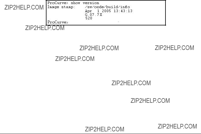
Screen Simulations
Figures containing simulated screen text and command output look like this:
Figure
In some cases, brief
ProCurve(config)# ip
ProCurve(config)# vlan 1 ip address 18.28.36.152/24
ProCurve(config)# vlan 1 ip igmp
Port Identity Examples
This guide describes software applicable to both

Note
Getting Started
Sources for More Information
Sources for More Information
For additional information about switch operation and features not covered in this guide, consult the following sources:
???For information on which product manual to consult on a given software feature, refer to ???Product Documentation??? on page xi.
For the latest version of all ProCurve switch documentation, including release notes covering recently added features, visit the ProCurve Networking website at http://www.procurve.com. Click on Technical support, and then click on Product manuals.
???For information on specific parameters in the menu interface, refer to the online help provided in the interface. For example:
Online Help for
Menu interface
Figure
???For information on a specific command in the CLI, type the command name followed by ???help???. For example:

Getting Started
Need Only a Quick Start?
Figure
???For information on specific features in the Web browser interface, use the online help. For more information, refer to the Management and Configuration Guide for your switch.
???For further information on ProCurve Networking switch technology, visit the ProCurve website at:
http://www.procurve.com
Need Only a Quick Start?
IP Addressing
If you just want to give the switch an IP address so that it can communicate on your network, or if you are not using multiple VLANs, ProCurve recommends that you use the Switch Setup screen to quickly configure IP addressing. To do so, do one of the following:
???Enter setup at the CLI Manager level prompt.
ProCurve# setup
???In the Main Menu of the Menu interface, select
8.Run Setup
For more on using the Switch Setup screen, see the Installation and Getting Started Guide you received with the switch.

Getting Started
Need Only a Quick Start?
To Set Up and Install the Switch in Your Network
Important!
Use the Installation and Getting Started Guide shipped with your switch for the following:
???Notes, cautions, and warnings related to installing and using the switch and its related modules
???Instructions for physically installing the switch in your network
???Quickly assigning an IP address and subnet mask, setting a Manager password, and (optionally) configuring other basic features.
???Interpreting LED behavior.
For the latest version of the Installation and Getting Started Guide and other documentation for your switch, visit the ProCurve website. (Refer to ???Product Documentation??? on page xi of this guide for further details.)

Getting Started
Need Only a Quick Start?
??? This page is intentionally unused. ???

2
Configuring Username and Password Security
Contents
Overview . . . . . . . . . . . . . . . . . . . . . . . . . . . . . . . . . . . . . . . . . . . . . . . . . . . . . .
Configuring Local Password Security . . . . . . . . . . . . . . . . . . . . . . . . . . . . . .
Menu: Setting Passwords . . . . . . . . . . . . . . . . . . . . . . . . . . . . . . . . . . . . .
CLI: Setting Passwords and Usernames . . . . . . . . . . . . . . . . . . . . . . . . .
Web: Setting Passwords and Usernames . . . . . . . . . . . . . . . . . . . . . . . .
When Security Is Important . . . . . . . . . . . . . . . . . . . . . . . . . . . . . . . . . . .
Configuring
Password Recovery . . . . . . . . . . . . . . . . . . . . . . . . . . . . . . . . . . . . . . . . .
Password Recovery Process . . . . . . . . . . . . . . . . . . . . . . . . . . . . . . . . .

Configuring Username and Password Security
Overview
Overview
The following features apply only to the Series 2600,
Console access includes both the menu interface and the CLI. There are two levels of console access: Manager and Operator. For security, you can set a password pair (username and password) on each of these levels.
*Allows use of the ping,
Note
Caution
Configuring Username and Password Security
Overview
To configure password security:
1.Set a Manager password pair (and an Operator password pair, if applicable for your system).
2.Exit from the current console session. A Manager password pair will now be needed for full access to the console.
If you do steps 1 and 2, above, then the next time a console session is started for either the menu interface or the CLI, a prompt appears for a password. Assuming you have protected both the Manager and Operator levels, the level of access to the console interface will be determined by which password is entered in response to the prompt.
If you set a Manager password, you may also want to configure the
Inactivity Time parameter. (Refer to the Management and Configuration Guide for your switch.) This causes the console session to end after the specified period of inactivity, thus giving you added security against unauthor- ized console access.
The manager and operator passwords and (optional) usernames control access to the menu interface, CLI, and web browser interface.
If you configure only a Manager password (with no Operator password), and in a later session the Manager password is not entered correctly in response to a prompt from the switch, then the switch does not allow management access for that session.
Passwords are
If the switch has neither a Manager nor an Operator password, anyone having access to the switch through either Telnet, the serial port, or the web browser interface can access the switch with full manager privileges. Also, if you configure only an Operator password, entering the Operator pass- word enables full manager privileges.
The rest of this section covers how to:
???Set passwords
???Delete passwords
???Recover from a lost password

Configuring Username and Password Security
Configuring Local Password Security
Configuring Local Password Security
Menu: Setting Passwords
As noted earlier in this section, usernames are optional. Configuring a user- name requires either the CLI or the web browser interface.
1.From the Main Menu select:
3. Console Passwords
Figure
2.To set a new password:
a.Select Set Manager Password or Set Operator Password. You will then be prompted with Enter new password.
b.Type a password of up to 16 ASCII characters with no spaces and press [Enter]. (Remember that passwords are
c.When prompted with Enter new password again, retype the new pass- word and press [Enter].
After you configure a password, if you subsequently start a new console session, you will be prompted to enter the password. (If you use the CLI or web browser interface to configure an optional username, the switch will prompt you for the username, and then the password.)
To Delete Password Protection (Including Recovery from a Lost
Password): This procedure deletes all usernames (if configured) and pass- words (Manager and Operator).
Configuring Username and Password Security
Configuring Local Password Security
If you have physical access to the switch, press and hold the Clear button (on the front of the switch) for a minimum of one second to clear all password protection, then enter new passwords as described earlier in this chapter.
If you do not have physical access to the switch, you will need
1.Enter the console at the Manager level.
2.Go to the Set Passwords screen as described above.
3.Select Delete Password Protection. You will then see the following prompt:
Continue Deletion of password protection? No
4.Press the Space bar to select Yes, then press [Enter].
5.Press [Enter] to clear the Password Protection message.
To Recover from a Lost Manager Password: If you cannot start a con- sole session at the Manager level because of a lost Manager password, you can clear the password by getting physical access to the switch and pressing and holding the Clear button for a minimum of one second. This action deletes all passwords and usernames (Manager and Operator) used by both the console and the web browser interface.
CLI: Setting Passwords and Usernames
Commands Used in This Section
Configuring Manager and Operator Passwords.
Syntax: [ no ] password <manager | operator > [
??? Password entries appear  as asterisks.
 ??? You must type the password entry twice.
Figure

Configuring Username and Password Security
Configuring Local Password Security
To Remove Password Protection. Removing password protection means to eliminate password security. This command prompts you to verify that you want to remove one or both passwords, then clears the indicated password(s). (This command also clears the username associated with a password you are removing.) For example, to remove the Operator password (and username, if assigned) from the switch, you would do the following:
Press [Y] (for yes) and press [Enter].
Figure
The effect of executing the command in figure
Web: Setting Passwords and Usernames
In the web browser interface you can enter passwords and (optional) user- names.
To Configure (or Remove) Usernames and Passwords in the Web
Browser Interface.
1. Click on the Security tab.
Click on [Device Passwords].
2.Do one of the following:
???To set username and password protection, enter the usernames and passwords you want in the appropriate fields.
???To remove username and password protection, leave the fields blank.
3.Implement the usernames and passwords by clicking on [Apply Changes].
To access the

Configuring Username and Password Security
The
The
???Resetting the password(s) by pressing the Clear button
???Restoring the factory default configuration by using the Reset+Clear button combination.
???Gaining management access to the switch by having physical access to the switch itself
When Security Is Important
Some customers require a high level of security for information. Also, the Health Insurance Portability and Accountability Act (HIPAA) of 1996 requires that systems handling and transmitting confidential medical records must be secure.
It used to be assumed that only system and network administrators would be able to get access to a network switch because switches were typically placed in secure locations under lock and key. For some customers this is no longer true. Others simply want the added assurance that even if someone did manage to get to the switch that data would still remain secure.
If you do not invoke

Configuring Username and Password Security
As a result of increased security concerns, customers now have the ability to stop someone from removing passwords by disabling the Clear and/or Reset buttons on the front of the switch.
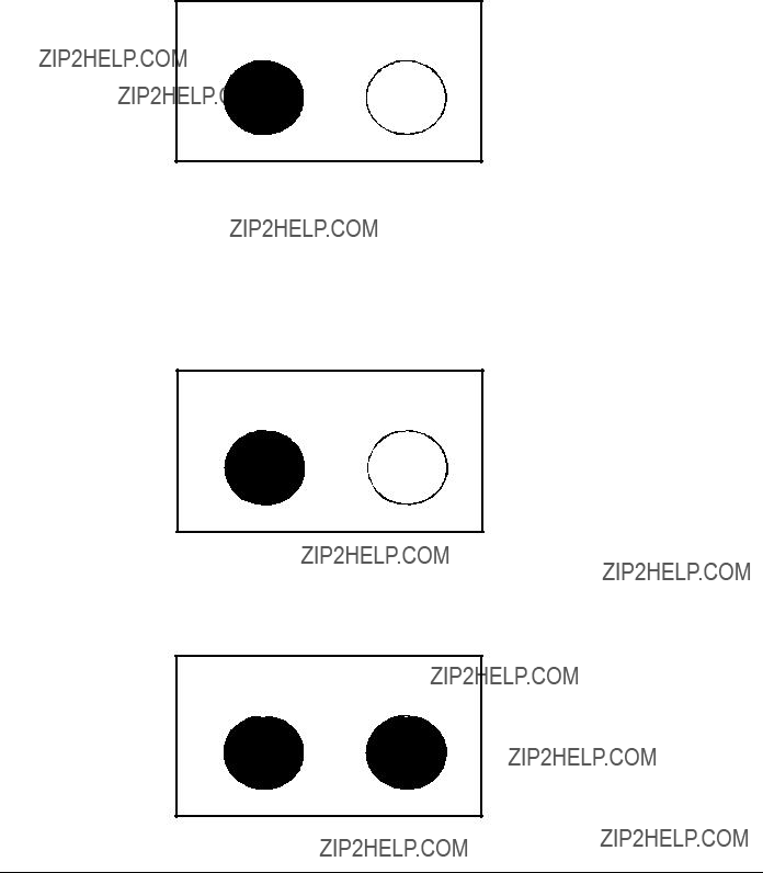
The front panel of the switch includes the Reset button and the Clear button.
Reset ButtonClear Button
Figure
Clear Button
Pressing the Clear button alone for one second resets the password(s) con- figured on the switch.
Figure
Configuring Username and Password Security
Reset Button
Pressing the Reset button alone for one second causes the switch to reboot.
Figure
Restoring the Factory Default Configuration
You can also use the Reset button together with the Clear button (Reset+Clear) to restore the factory default configuration for the switch. To do this:
1.Press and hold the Reset button.
2.While holding the Reset button, press and hold the Clear button.
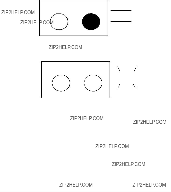
Configuring Username and Password Security
3.Release the Reset button and wait for about one second for the
Self
Test
4. When the
.
Self
Test
This process restores the switch configuration to the factory default settings.
Configuring
Using the
???Disable or
???Configure the Clear button to reboot the switch after clearing any local usernames and passwords. This provides an immediate, visual means (plus an Event Log message) for verifying that any usernames and passwords in the switch have been cleared.

Configuring Username and Password Security
???Modify the operation of the Reset+Clear combination (page
???Disable or
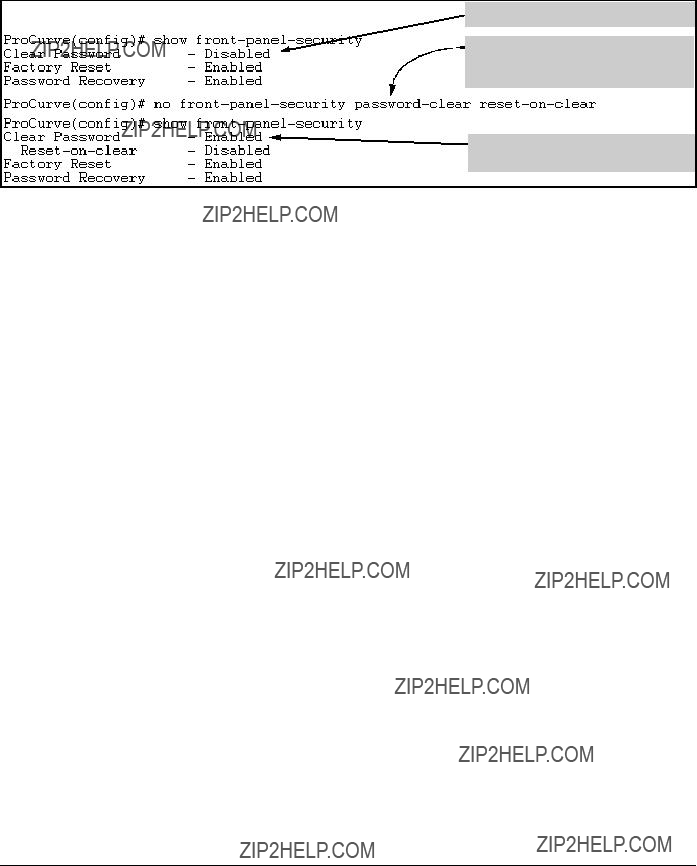
Syntax: show
Displays the current
Clear Password: Shows the status of the Clear button on the front panel of the switch. Enabled means that pressing the Clear button erases the local usernames and passwords configured on the switch (and thus removes local password protection from the switch). Disabled means that pressing the Clear button does not remove the local usernames and passwords configured on the switch. (Default: Enabled.)
Factory Reset: Shows the status of the Reset button on the front panel of the switch. Enabled means that pressing the Reset button reboots the switch and also enables the Reset button to be used with the Clear button (page
Password Recovery: Shows whether the switch is configured with the ability to recover a lost password. (Refer to ???Password Recovery Process??? on page
Enabled.)
CAUTION: Disabling this option removes the ability to recover a password on the switch. Disabling this option is an extreme measure and is not recommended unless you have the most urgent need for high security. If you disable

Configuring Username and Password Security
For example, show
Figure
Disabling the Clear Password Function of the Clear Button on the Switch???s Front Panel
Syntax: no
In the
Note: Although the Clear button does not erase passwords when disabled, you can still use it with the Reset button (Reset+Clear) to restore the switch to its factory default configuration, as described under ???Restoring the Factory Default Configuration??? on page
This command displays a Caution message in the CLI. If you want to proceed with disabling the Clear button, type [Y]; otherwise type [N]. For example:
Indicates the command has disabled the Clear button on the switch???s front panel. In this case the Show command does not include the reset-
Figure
Configuring Username and Password Security
Syntax: [no]
This command does both of the following:
???
???Specifies whether the switch reboots if the Clear button is pressed.
To
Defaults:
???
???
???To enable
no
???To enable
(Either form of the command enables
Note: If you disable
For example, suppose that
Configuring Username and Password Security
Shows
Enables
Shows
Figure
Changing the Operation of the Reset+Clear Combination
In their default configuration, using the Reset+Clear buttons in the combina- tion described under ???Restoring the Factory Default Configuration??? on page
Syntax: [no]
Disables or
???Replacing the current
???Clearing any local usernames and passwords configured on the switch
(Default: Both functions enabled.)
Notes: The Reset+Clear button combination always reboots the switch, regardless of whether the ???no??? form of the command has been used to disable the above two functions. Also, if you disable
Configuring Username and Password Security
The command to disable the
To complete the command, press [Y]. To abort the command, press [N].
Completes the command to disable the factory reset option.
Displays the current front-
Figure
Password Recovery
The password recovery feature is enabled by default and provides a method for regaining management access to the switch (without resetting the switch to its factory default configuration) in the event that the system administrator loses the local manager username (if configured) or password. Using Pass- word Recovery requires:
???
???Contacting your ProCurve Customer Care Center to acquire a

Configuring Username and Password Security
Syntax: [no]
Enables or (using the ???no??? form of the command) disables the ability to recover a lost password.
When this feature is enabled, the switch allows management access through the password recovery process described below. This provides a method for recovering from a lost manager username (if configured) and password. When this feature is disabled, the password recovery process is disabled and the only way to regain management access to the switch is to use the Reset+Clear button combination (page
Note: To disable
???You must have physical access to the front panel of the switch.
???The
(Default: Enabled.)
Steps for Disabling
1.Set the CLI to the global interface context.
2.Use show
3.Press and release the Clear button on the front panel of the switch.
4.Within
no
5.Do one of the following after the ???CAUTION??? message appears:
???If you want to complete the command, press [Y] (for ???Yes???).
???If you want to abort the command, press [N] (for ???No???)
Figure

Configuring Username and Password Security
Figure
N o t e
N o t e
Password Recovery Process
If you have lost the switch???s manager username/password, but password- recovery is enabled, then you can use the Password Recovery Process to gain
management access to the switch with an alternate password supplied by ProCurve.
If you have disabled
To use the
1.Note the switch???s base MAC address. It is shown on the label located on the upper right front corner of the switch.
2.Contact your ProCurve Customer Care Center for further assistance. Using the switch???s MAC address, the ProCurve Customer Care Center will generate and provide a
The alternate password provided by the ProCurve Customer Care Center is valid only for a single login attempt.
You cannot use the same

Configuring Username and Password Security
??? This page is intentionally unused. ???

3
Web and MAC Authentication for the Series
Contents
Overview . . . . . . . . . . . . . . . . . . . . . . . . . . . . . . . . . . . . . . . . . . . . . . . . . . . . . .
Client Options . . . . . . . . . . . . . . . . . . . . . . . . . . . . . . . . . . . . . . . . . . . . . .
General Features . . . . . . . . . . . . . . . . . . . . . . . . . . . . . . . . . . . . . . . . . . . .
How Web and MAC Authentication Operate . . . . . . . . . . . . . . . . . . . . . . . .
Authenticator Operation . . . . . . . . . . . . . . . . . . . . . . . . . . . . . . . . . . . . .
Terminology . . . . . . . . . . . . . . . . . . . . . . . . . . . . . . . . . . . . . . . . . . . . . . . . . . .
Operating Rules and Notes . . . . . . . . . . . . . . . . . . . . . . . . . . . . . . . . . . . . . .
General Setup Procedure for Web/MAC Authentication . . . . . . . . . . . . . .
Additional Information for Configuring the RADIUS Server
To Support MAC Authentication . . . . . . . . . . . . . . . . . . . . . . . . . . . . . .
Configuring the Switch To Access a RADIUS Server . . . . . . . . . . . . . . . .
Configuring Web Authentication . . . . . . . . . . . . . . . . . . . . . . . . . . . . . . . . .
Configuring MAC Authentication on the Switch . . . . . . . . . . . . . . . . . . . .
Show Status and Configuration of
Show Status and Configuration of
Show Client Status . . . . . . . . . . . . . . . . . . . . . . . . . . . . . . . . . . . . . . . . . . . . .

Web and MAC Authentication for the Series
Overview
Overview
Applicable Switch Models. Web and MAC Authentication are available on these current ProCurve switch models:
???ProCurve Series 2600 and
???ProCurve Series 2800 Switches
Web and MAC Authentication are designed for employment on the ???edge??? of a network to provide
Web Authentication

Web and MAC Authentication for the Series
Overview
Client Options
In the default configuration, the switch blocks access to clients that the RADIUS server does not authenticate. However, you can configure an individ- ual port to provide limited services to unauthorized clients by joining a specified ???unauthorized??? VLAN during sessions with such clients. The unau- thorized VLAN assignment can be the same for all ports, or different, depend- ing on the services and access you plan to allow for unauthenticated clients.
Access to an optional, unauthorized VID is configured in the switch when Web and MAC Authentication are configured on a port.

Web and MAC Authentication for the Series
Overview
General Features
Web and MAC Authentication on the ProCurve Series 2600,
???On a port configured for Web or MAC Authentication, the switch operates as a
???Proxy servers may not be used by browsers accessing the switch through ports using Web Authentication.
???You can optionally configure the switch to temporarily assign ???autho- rized??? and ???unauthorized??? VLAN memberships on a
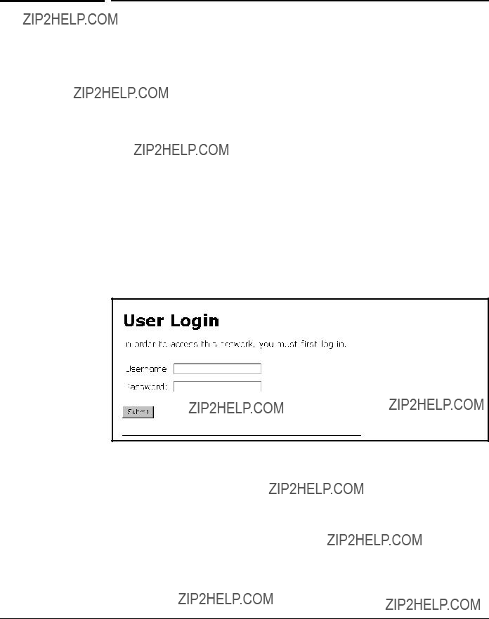
???Web pages for username and password entry and the display of authorization status are provided when using Web Authentication.
???You can use the RADIUS server to temporarily assign a port to a static VLAN to support an authenticated client. When a RADIUS server authenticates a client, the
1.A
2.An authorized VLAN specified in the Web- or
3.A static,
???You can allow wireless clients to move between switch ports under Web/MAC Authentication control. Clients may move from one Web authorized port to another or from one MAC authorized port to another. This capability allows wireless clients to move from one access point to another without having to reauthenticate.
???Unlike 802.1X operation, clients do not need supplicant software for Web or MAC Authentication; only a web browser (for Web Authenti- cation) or a MAC address (for MAC Authentication).
???You can use ???Show??? commands to display session status and port- access configuration settings.
Web and MAC Authentication for the Series
How Web and MAC Authentication Operate
How Web and MAC Authentication
Operate
Authenticator Operation
Before gaining access to the network clients first present their authentication credentials to the switch. The switch then verifies the supplied credentials with a RADIUS authentication server. Successfully authenticated clients receive access to the network, as defined by the System Administrator. Clients who fail to authenticate successfully receive no network access or limited network access as defined by the System Administrator.
When a client connects to a
Figure
The temporary IP address pool can be specified using the
The switch passes the supplied username and password to the RADIUS server for authentication.

Web and MAC Authentication for the Series
How Web and MAC Authentication Operate
Figure
If the client is authenticated and the maximum number of clients allowed on the port
Figure
The assigned VLAN is determined, in order of priority, as follows:
1.If there is a
2.If there is no
3.If neither 1 or 2, above, apply, but the port is an untagged member of a statically configured,
4.If neither 1, 2, or 3, above, apply, then the client session does not have access to any statically configured, untagged VLANs and client access is blocked.
The assigned port VLAN remains in place until the session ends. Clients may be forced to reauthenticate after a fixed period of time
Web and MAC Authentication for the Series
How Web and MAC Authentication Operate
moves have not been enabled
A client may not be authenticated due to invalid credentials or a RADIUS server timeout. The
Network administrators may assign unauthenticated clients to a specific static, untagged VLAN
When a client connects to a
If the client is authenticated and the maximum number of MAC addresses allowed on the port
The assigned VLAN is determined, in order of priority, as follows:
1.If there is a
2.If there is no
3.If neither 1 or 2, above, apply, but the port is an untagged member of a statically configured,

Web and MAC Authentication for the Series
How Web and MAC Authentication Operate
4.If neither 1, 2, or 3, above, apply, then the client session does not have access to any statically configured, untagged VLANs and client access is blocked.
The assigned port VLAN remains in place until the session ends. Clients may be forced to reauthenticate after a fixed period of time
A client may not be authenticated due to invalid credentials or a RADIUS server timeout. The
Network administrators may assign unauthenticated clients to a specific static, untagged VLAN

Web and MAC Authentication for the Series
Terminology
Terminology
Authentication Server: The entity providing an authentication service to the switch, for example, a RADIUS server.
Authenticator: In ProCurve switch applications, a device that requires a client or device to provide the proper credentials (MAC address, or username and password) before being allowed access to the network.
CHAP: Challenge Handshake Authentication Protocol. Also known as
Client: In this application, an
Redirect URL: A System
Static VLAN: A VLAN that has been configured as ???permanent??? on the switch by using the CLI vlan < vid > command or the Menu interface.

Web and MAC Authentication for the Series
Operating Rules and Notes
Operating Rules and Notes
??? You can configure one type of authentication on a port. That is, the following authentication types are mutually exclusive on a given port:
for Web or MAC Authentication. If Port Security is enabled on the port this misconfiguration does not allow Web or MAC Authentication to occur.
??? VLANs: If your LAN does not use multiple VLANs, then you do not need to configure VLAN assignments in your RADIUS server or consider using either Authorized or Unauthorized VLANs. If your LAN does use multiple VLANs, then some of the following factors may apply to your use of
???
??? A port can belong to one, untagged VLAN during any client session. Where multiple authenticated clients may simultaneously use the same port, they must all be capable of operating on the same VLAN.
??? During an authenticated client session, the following hierarchy deter- mines a port???s VLAN membership:
1. If there is a

Web and MAC Authentication for the Series
Operating Rules and Notes
2.If there is no
3.If neither 1 or 2, above, apply, but the port is an untagged member of a statically configured,
4.If neither 1, 2, or 3, above, apply, then the client session does not have access to any statically configured, untagged VLANs and client access is blocked.
???After an authorized client session begins on a given port, the port???s VLAN membership does not change. If other clients on the same port become authenticated with a different VLAN assignment than the first client, the port blocks access to these other clients until the first client session ends.
???The optional ???authorized??? VLAN
???Where a given port???s configuration includes an unauthorized client VLAN assignment, the port will allow an unauthenticated client session only while there are no requests for an authenticated client session on that port. In this case, if there is a successful request for authentication from an authorized client, the switch terminates the
???When a port on the switch is configured for Web or MAC Authentica- tion and is supporting a current session with another device, rebooting the switch invokes a
???When a port on the switch is configured as a Web- or
???Web- or
Web and MAC Authentication for the Series
General Setup Procedure for Web/MAC Authentication
Note on Web/
MAC Authentication and LACP
The switch does not allow Web or MAC Authentication and LACP to both be enabled at the same time on the same port. The switch automatically disables LACP on ports configured for Web or MAC Authentication.
Do These Steps Before You Configure Web/MAC
Authentication
1.Configure a local username and password on the switch for both the Operator (login) and Manager (enable) access levels. (While this is not required for a Web- or
2.Determine which ports on the switch you want to operate as authentica- tors. Note that before you configure Web- or
3.Determine whether any VLAN assignments are needed for authenticated clients.

Web and MAC Authentication for the Series
General Setup Procedure for Web/MAC Authentication
a.If you configure the RADIUS server to assign a VLAN for an authen- ticated client, this assignment overrides any VLAN assignments con- figured on the switch while the authenticated client session remains active. Note that the VLAN must be statically configured on the switch.
b.If there is no
c.If there is neither a
Note that when configuring a RADIUS server to assign a VLAN, you can use either the VLAN???s name or VID. For example, if a VLAN configured in the switch has a VID of 100 and is named vlan100, you could configure the RADIUS server to use either ???100??? or ???vlan100??? to specify the VLAN.
4.Determine whether to use the optional ???Unauthorized VLAN??? mode for clients that the RADIUS server does not authenticate. This VLAN must be statically configured on the switch. If you do not configure an ???Unauthor- ized VLAN???, the switch simply blocks access to unauthenticated clients trying to use the port.
5.Determine the authentication policy you want on the RADIUS server and configure the server. Refer to the documentation provided with your RADIUS application and include the following in the policy for each client or client device:
???The
???An encryption key
???One of the following:
???If you are configuring
???If you are configuring
6.Determine the IP address of the RADIUS server(s) you will use to support Web- or

Web and MAC Authentication for the Series
General Setup Procedure for Web/MAC Authentication
Additional Information for Configuring the RADIUS
Server To Support MAC Authentication
On the RADIUS server, configure the client device authentication in the same way that you would any other client, except:
???Configure the client device???s (hexadecimal) MAC address as both username and password. Be careful to configure the switch to use the same format that the RADIUS server uses. Otherwise, the server will deny access. The switch provides four format options:
aabbccddeeff (the default format)
aa:bb:cc:dd:ee:ff
Note on MAC Letters in MAC addresses must be in lowercase.
Addresses
???If the device is a switch or other

Web and MAC Authentication for the Series
Configuring the Switch To Access a RADIUS Server
Configuring the Switch To Access a
RADIUS Server
This section describes the minimal commands for configuring a RADIUS server to support
Syntax: [no]
[host <
Adds a server to the RADIUS configuration or (with no) deletes a server from the configuration. You can config- ure up to three RADIUS server addresses. The switch uses the first server it successfully accesses. (Refer to ???RADIUS Authentication and Accounting??? on page
[key <
Specifies the global encryption key the switch uses with servers for which the switch does not have a server- specific key assignment (below). This key is optional if all RADIUS server addresses configured in the switch include a
Syntax:
Web and MAC Authentication for the Series
Configuring the Switch To Access a RADIUS Server
Optional. Specifies an encryption key for use during authentication (or accounting) sessions with the speci- fied server. This key must match the encryption key used on the RADIUS server. Use this command only if the specified server requires a different encryption key than configured for the global encryption key, above.
The no form of the command removes the key configured for a specific server.
For example, to configure the switch to access a RADIUS server at IP address 192.168.32.11 using a
ProCurve(config)#
ProCurve(config)# show radius
Status and Counters - General RADIUS Information
ProCurve(config)#
Figure
Web and MAC Authentication for the Series
Configuring Web Authentication
Configuring Web Authentication
This feature is available only on the Series 2600,
Overview

Web and MAC Authentication for the Series
Configuring Web Authentication
Configure the Switch for
Syntax: aaa
Specifies the base address/mask for the temporary IP pool used by DHCP. The base address can be any valid ip address (not a multicast address). Valid mask range value is <255.255.240.0 - 255.255.255.0>.
(Default: 192.168.0.0/255.255.255.0)
Syntax: aaa
Specifies the lease length, in seconds, of the temporary IP address issued for Web Auth login purposes. (Default: 10 seconds)

Web and MAC Authentication for the Series
Configuring Web Authentication
Syntax: [no] aaa
Enables
Syntax: aaa
Specifies the VLAN to use for an authorized client. The Radius server can override the value
Use the no form of the command to set the
Syntax: aaa
Specifies the maximum number of authenticated clients to allow on the port. (Default: 1)
Syntax: [no] aaa
Allows client moves between the specified ports under Web Auth control. When enabled, the switch allows clients to move without requiring a
Use the no form of the command to disable client moves between ports under Web Auth control.
(Default: disabled ??? no moves allowed)

Web and MAC Authentication for the Series
Configuring Web Authentication
Syntax: aaa
Specifies the period, in seconds, that the switch enforces for an implicit logoff. This parameter is equivalent to the MAC age interval in a traditional switch sense. If the switch does not see activity after a
Syntax: aaa
Specifies the number of authentication attempts that must
(Default: 2)
Syntax: aaa
Specifies the number of the number of times a client can enter their user name and password before authen- tication fails. This allows the reentry of the user name and password if necessary.
(Default: 3)
Syntax: aaa
Specifies the time period, in seconds, the switch should wait before attempting an authentication request for a client that failed authentication.
(Default: 60 seconds)
Syntax: aaa
Specifies the time period, in seconds, the switch enforces on a client to
Syntax: aaa
Forces a reauthentication of all attached clients on the port.

Web and MAC Authentication for the Series
Configuring Web Authentication
Syntax: aaa
Specifies the URL that a user is redirected to after a successful login. Any valid,
Use the no form of the command to remove a specified redirect URL.
(Default: There is no default URL. Browser behavior for authenticated clients may not be acceptable.)
Syntax: aaa
Specifies the period, in seconds, the switch waits for a server response to an authentication request. Depend- ing on the current
(Default: 30 seconds)
Syntax: [no] aaa
Enables or disables SSL login (https on port 443). SSL must be enabled on the switch.
If SSL login is enabled, a user is redirected to a secure page, where they enter their username and password. If SSL login is disabled, a user is not redirected to a secure page to enter their credentials.
Use the no form of the command to disable SSL login. (Default: disabled)
Syntax: aaa
Specifies the VLAN to use for a client that fails authen- tication. If
Use the no form of the command to set the

Web and MAC Authentication for the Series
Configuring MAC Authentication on the Switch
Configuring MAC Authentication on the
Switch
This feature is available only on the Series 2600,
Switches.
Overview
1.If you have not already done so, configure a local username and password pair on the switch.
2.If you plan to use multiple VLANs with MAC Authentication, ensure that these VLANs are configured on the switch and that the appropriate port assignments have been made.
3.Use the ping command in the switch console interface to ensure that the switch can communicate with the RADIUS server you have configured to support
4.Configure the switch with the correct IP address and encryption key to access the RADIUS server.
5.Configure the switch for
a. Configure MAC Authentication on the switch ports you want to use.
6.Test both the authorized and unauthorized access to your system to ensure that MAC Authentication works properly on the ports you have configured for

Web and MAC Authentication for the Series
Configuring MAC Authentication on the Switch
Configure the Switch for
Syntax: aaa
Specifies the MAC address format to be used in the RADIUS request message. This format must match the format used to store the MAC addresses in the RADIUS server. (Default:
Syntax: [no] aaa
Enables

Web and MAC Authentication for the Series
Configuring MAC Authentication on the Switch
Syntax: aaa
Specifies the maximum number of authenticated
MACs to allow on the port. (Default: 1)
Syntax: [no] aaa
Syntax:
Syntax:
Allows client moves between the specified ports under MAC Auth control. When enabled, the switch allows addresses to move without requiring a
Use the no form of the command to disable MAC address moves between ports under MAC Auth control. (Default: disabled ??? no moves allowed)
aaa
Specifies the VLAN to use for an authorized client. The Radius server can override the value
Use the no form of the command to set the
aaa
Specifies the period, in seconds, that the switch enforces for an implicit logoff. This parameter is equivalent to the MAC age interval in a traditional switch sense. If the switch does not see activity after a
Syntax: aaa
Specifies the number of authentication attempts that must
(Default: 2)

Web and MAC Authentication for the Series
Configuring MAC Authentication on the Switch
Syntax: aaa
Specifies the time period, in seconds, the switch should wait before attempting an authentication request for a MAC address that failed authentication.
(Default: 60 seconds)
Syntax: aaa
Specifies the time period, in seconds, the switch enforces on a client to
Syntax: aaa
Forces a reauthentication of all attached clients on the port.
Syntax: aaa
Specifies the period, in seconds, the switch waits for a server response to an authentication request. Depend- ing on the current
(Default: 30seconds)
Syntax: aaa
Specifies the VLAN to use for a client that fails authen- tication. If
Use the no form of the command to set the
Web and MAC Authentication for the Series
Show Status and Configuration of
Show Status and Configuration of
Syntax: show
Shows the status of all
Syntax: show
Shows the port address, Web address, session status, and elapsed session time for attached clients on all ports or the specified ports. Ports with multiple clients have an entry for each attached client. Ports without any attached clients are not listed.
Syntax: show
Shows Web Authentication settings for all ports or the specified ports, including the temporary DHCP base address and mask. The authorized and unauthorized VLAN IDs are shown. If the authorized or unauthor- ized VLAN ID is 0 then no VLAN change is made, unless the RADIUS server supplies one.
Web and MAC Authentication for the Series
Show Status and Configuration of
Syntax: show
Shows Web Authentication settings for all ports or the specified ports, along with the RADIUS server specific settings for the timeout wait, the number of timeout failures before authentication fails, and the length of time between authentication requests.
Syntax: show
Shows Web Authentication settings for all ports or the specified ports, along with the web specific settings for password retries, SSL login status, and a redirect URL, if specified.
Syntax: show
Shows all Web Authentication settings, including the
Radius server specific settings for the specified ports.
Show Status and Configuration of
Syntax: show
Shows the status of all

Web and MAC Authentication for the Series
Show Status and Configuration of
Syntax: show
Shows the port address, MAC address, session status, and elapsed session time for attached clients on all ports or the specified ports. Ports with multiple clients have an entry for each attached client. Ports without any attached clients are not listed.
Syntax: show
Shows MAC Authentication settings for all ports or the specified ports, including the MAC address format being used. The authorized and unauthorized VLAN IDs are shown. If the authorized or unauthorized VLAN ID is 0 then no VLAN change is made, unless the RADIUS server supplies one.
Syntax: show
Shows MAC Authentication settings for all ports or the specified ports, along with the Radius server specific settings for the timeout wait, the number of timeout failures before authentication fails, and the length of time between authentication requests.
Syntax: show
Shows all MAC Authentication settings, including the
Radius server specific settings for the specified ports.

Web and MAC Authentication for the Series
Show Client Status
Show Client Status
The table below shows the possible client status information that may be reported by a

Web and MAC Authentication for the Series
Show Client Status
??? This page is intentionally unused. ???

4
TACACS+ Authentication
Contents
Overview . . . . . . . . . . . . . . . . . . . . . . . . . . . . . . . . . . . . . . . . . . . . . . . . . . . . . .
Terminology Used in TACACS Applications: . . . . . . . . . . . . . . . . . . . . . . . .
General System Requirements . . . . . . . . . . . . . . . . . . . . . . . . . . . . . . . . . . . .
General Authentication Setup Procedure . . . . . . . . . . . . . . . . . . . . . . . . . . .
Configuring TACACS+ on the Switch . . . . . . . . . . . . . . . . . . . . . . . . . . . . . .
Viewing the Switch???s Current TACACS+ Server
Contact Configuration . . . . . . . . . . . . . . . . . . . . . . . . . . . . . . . . . . . . . .
Configuring the Switch???s Authentication Methods . . . . . . . . . . . . . . .
Configuring the Switch???s TACACS+ Server Access . . . . . . . . . . . . . .
Controlling Web Browser Interface Access When Using TACACS+
Authentication . . . . . . . . . . . . . . . . . . . . . . . . . . . . . . . . . . . . . . . . . . . . . . . .
Messages Related to TACACS+ Operation . . . . . . . . . . . . . . . . . . . . . . . . .
Operating Notes . . . . . . . . . . . . . . . . . . . . . . . . . . . . . . . . . . . . . . . . . . . . . . .
TACACS+ Authentication
Configuring TACACS+ on the Switch
Overview
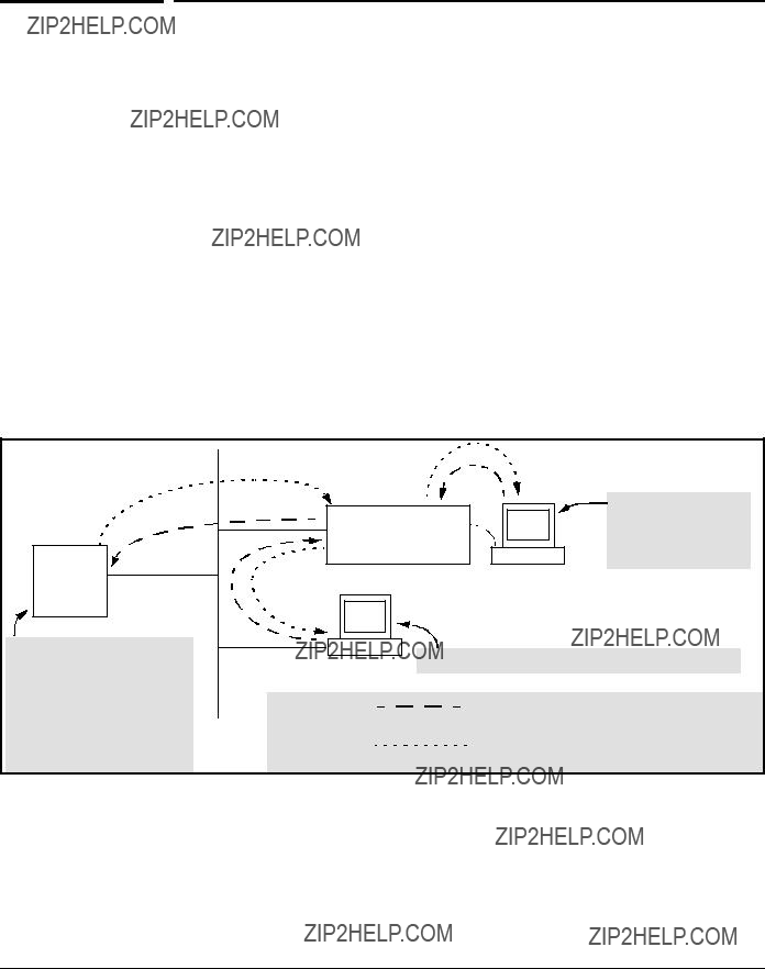
TACACS+ authentication enables you to use a central server to allow or deny access to the switch (and other
Figure
TACACS+ in the switch manages authentication of logon attempts through either the Console port or Telnet. TACACS+ uses an authentication hierarchy consisting of (1) remote passwords assigned in a TACACS+ server and (2) local passwords configured on the switch. That is, with TACACS+ configured, the switch first tries to contact a designated TACACS+ server for authentica-

Notes
TACACS+ Authentication
Configuring TACACS+ on the Switch
tion services. If the switch fails to connect to any TACACS+ server, it defaults to its own locally assigned passwords for authentication control if it has been configured to do so. For both Console and Telnet access you can configure a login
The software does not support TACACS+ authorization or accounting services.
TACACS+ does not affect web browser interface access. See ???Controlling Web Browser Interface Access??? on page
Terminology Used in TACACS
Applications:
???NAS (Network Access Server): This is an industry term for a
???TACACS+ Server: The server or management station configured as an access control server for
???Authentication: The process for granting user access to a device through entry of a user name and password and comparison of this username/password pair with previously stored username/password data. Authentication also grants levels of access, depending on the privileges assigned to a user name and password pair by a system administrator.

TACACS+ Authentication
Configuring TACACS+ on the Switch
???Local Authentication: This method uses username/password pairs configured locally on the switch; one pair each for manager- level and
???TACACS+ Authentication: This method enables you to use a TACACS+ server in your network to assign a unique password, user name, and privilege level to each individual or group who needs access to one or more switches or other
Notes
TACACS+ Authentication
Configuring TACACS+ on the Switch
General System Requirements
To use TACACS+ authentication, you need the following:
???A TACACS+ server application installed and configured on one or more servers or management stations in your network. (There are several TACACS+ software packages available.)
???A switch configured for TACACS+ authentication, with access to one or more TACACS+ servers.
The effectiveness of TACACS+ security depends on correctly using your TACACS+ server application. For this reason, ProCurve recommends that you thoroughly test all TACACS+ configurations used in your network.
TACACS+ does not affect web browser interface access. Refer to ???Controlling Web Browser Interface Access When Using TACACS+ Authentication??? on page
General Authentication Setup Procedure
It is important to test the TACACS+ service before fully implementing it. Depending on the process and parameter settings you use to set up and test TACACS+ authentication in your network, you could accidentally lock all users, including yourself, out of access to a switch. While recovery is simple, it may pose an inconvenience that can be avoided.To prevent an unintentional lockout on a switch, use a procedure that configures and tests TACACS+ protection for one access type (for example, Telnet access), while keeping the

TACACS+ Authentication
Configuring TACACS+ on the Switch
other access type (console, in this case) open in case the Telnet access fails due to a configuration problem. The following procedure outlines a general setup procedure.
3. Plan and enter the TACACS+ server configuration needed to support TACACS+ operation for Telnet access (login and enable) to the switch. This includes the username/password sets for logging in at the Operator
TACACS+ Authentication
Configuring TACACS+ on the Switch
Note on Privilege Levels
Caution
When a TACACS+ server authenticates an access request from a switch, it includes a privilege level code for the switch to use in determining which privilege level to grant to the terminal requesting access. The switch interprets a privilege level code of ???15??? as authorization for the Manager (read/write) privilege level access. Privilege level codes of 14 and lower result in Operator
If you are a
4.Ensure that the switch has the correct local username and password for Manager access. (If the switch cannot find any designated TACACS+ servers, the local manager and operator username/password pairs are always used as the secondary access control method.)
You should ensure that the switch has a local Manager password. Other- wise, if authentication through a TACACS+ server fails for any reason, then unauthorized access will be available through the console port or Telnet.
5.Using a terminal device connected to the switch???s console port, configure the switch for TACACS+ authentication only for telnet login access and telnet enable access. At this stage, do not configure TACACS+ authenti- cation for console access to the switch, as you may need to use the console for access if the configuration for the Telnet method needs debugging.
6.Ensure that the switch is configured to operate on your network and can communicate with your
7.On a remote terminal device, use Telnet to attempt to access the switch. If the attempt fails, use the console access to check the TACACS+ configuration on the switch. If you make changes in the switch configu- ration, check Telnet access again. If Telnet access still fails, check the

TACACS+ Authentication
Configuring TACACS+ on the Switch
configuration in your TACACS+ server application for
8.After your testing shows that Telnet access using the TACACS+ server is working properly, configure your TACACS+ server application for console access. Then test the console access. If access problems occur, check for and correct any problems in the switch configuration, and then test console access again. If problems persist, check your TACACS+ server application for
9.When you are confident that TACACS+ access through both Telnet and the switch???s console operates properly, use the write memory command to save the switch???s
Configuring TACACS+ on the Switch
Before You Begin
If you are new to TACACS+ authentication, ProCurve recommends that you read the ???General Authentication Setup Procedure??? on page
The switch offers three command areas for TACACS+ operation:
???show authentication and show tacacs: Displays the switch???s TACACS+ configuration and status.
???aaa authentication: A command for configuring the switch???s authenti- cation methods
???

TACACS+ Authentication
Configuring TACACS+ on the Switch
CLI Commands Described in this Section
Viewing the Switch???s Current Authentication
Configuration
This command lists the number of login attempts the switch allows in a single login session, and the primary/secondary access methods configured for each type of access.
Syntax: show authentication
This example shows the default authentication configuration.
Configuration for login and enable access to the switch through the switch console port.
Configuration for login and enable access to the switch through Telnet.
Figure

TACACS+ Authentication
Configuring TACACS+ on the Switch
Viewing the Switch???s Current TACACS+ Server Contact
Configuration
This command lists the timeout period, encryption key, and the IP addresses of the
Syntax: show tacacs
For example, if the switch was configured for a
TACACS+ Server
TACACS+ Server 
TACACS+ Server
Figure

TACACS+ Authentication
Configuring TACACS+ on the Switch
Configuring the Switch???s Authentication Methods
The aaa authentication command configures the access control for console port and Telnet access to the switch. That is, for both access methods, aaa authentication specifies whether to use a TACACS+ server or the switch???s local authentication, or (for some secondary scenarios) no authentication (meaning that if the primary method fails, authentication is denied). This command also reconfigures the number of access attempts to allow in a session if the first attempt uses an incorrect username/password pair.
Syntax: aaa authentication
< console | telnet >
Selects either console (serial port) or Telnet access for configuration.
< enable | login >
Selects either the Manager (enable) or Operator (login) access level.
< local | tacacs | radius >
Selects the type of security access:
local ??? Authenticates with the Manager and Operator password you configure in the switch.
tacacs ??? Authenticates with a password and other data configured on a TACACS+ server.
radius ??? Authenticates with a password and other data configured on a RADIUS server. (Refer to ???RADIUS Authentication and Accounting??? on page
[< local | none >]
If the primary authentication method fails, determines whether to use the local password as a secondary method or to disallow access.
aaa authentication
Specifies the maximum number of login attempts allowed in the current session. Default: 3

TACACS+ Authentication
Configuring TACACS+ on the Switch
Table
As shown in the next table, login and enable access is always available locally through a direct terminal connection to the switch???s console port. However, for Telnet access, you can configure TACACS+ to deny access if a TACACS+ server goes down or otherwise becomes unavailable to the switch.

TACACS+ Authentication
Configuring TACACS+ on the Switch
Table
*When ???local??? is the primary option, you can also select ???local??? as the secondary option. However, in this case, a secondary ???local??? is meaningless because the switch has only one local level of username/password protection.

TACACS+ Authentication
Configuring TACACS+ on the Switch
For example, here is a set of access options and the corresponding commands to configure them:
Console Login (Operator or
Secondary using Local.
ProCurve (config)# aaa authentication console login tacacs local
Console Enable (Manager or Read/Write) Access: Primary using TACACS+ server. Secondary using Local.
ProCurve (config)# aaa authentication console enable tacacs local
Telnet Login (Operator or
Secondary using Local.
ProCurve (config)# aaa authentication Telnet login tacacs local
Telnet Enable (Manager or Read/Write Access: Primary using TACACS+ server.
Secondary using Local.
ProCurve (config)# aaa authentication telnet enable tacacs local
Deny Access and Close the Session After Failure of Two Consecutive Username/Password Pairs:
ProCurve (config)# aaa authentication

TACACS+ Authentication
Configuring TACACS+ on the Switch
Configuring the Switch???s TACACS+ Server Access
The
??? The host IP address(es) for up to three TACACS+ servers; one first- choice and up to two backups. Designating backup servers provides for a continuation of authentication services in case the switch is unable to contact the
??? An optional encryption key. This key helps to improve security, and must match the encryption key used in your TACACS+ server appli- cation. In some applications, the term ???secret key??? or ???secret??? may be used instead of ???encryption key???. If you need only one encryption key for the switch to use in all attempts to authenticate through a TACACS+ server, configure a global key. However, if the switch is configured to access multiple TACACS+ servers having different encryption keys, you can configure the switch to use different encryp- tion keys for different TACACS+ servers.
??? The timeout value in seconds for attempts to contact a TACACS+

TACACS+ Authentication
Configuring TACACS+ on the Switch
Syntax:
Adds a TACACS+ server and optionally assigns a
[no]
Removes a TACACS+ server assignment (including its server- specific encryption key, if any).
Enters the optional global encryption key.
[no]
Removes the optional global encryption key. (Does not affect any
Changes the wait period for a TACACS server response. (Default: 5 seconds.)
Note on Encryption Keys
Encryption keys configured in the switch must exactly match the encryption keys configured in TACACS+ servers the switch will attempt to use for authentication.
If you configure a global encryption key, the switch uses it only with servers for which you have not also configured a
If TACACS+ server ???X??? does not have an encryption key assigned for the switch, then configuring either a global encryption key or a
TACACS+ Authentication
Configuring TACACS+ on the Switch
Table
This command specifies the IP address of a device running a TACACS+ server application. Optionally, it can also specify the unique,
You can enter up to three IP addresses; one
Use show tacacs to view the current IP address list.
If the
(See figure
The priority
1.When there are no TACACS+ servers configured, entering a server IP address makes that server the
2.When there is one TACACS+ serves already configured, entering another server IP address makes that server the
3.When there are two TACACS+ servers already configured, entering another server IP address makes that server the
???The above position assignments are fixed. Thus, if you remove one server and replace it with another, the new server assumes the priority position that the removed server had. For example, suppose you configured three servers, A, B, and C, configured in order:
???If you removed server B and then entered server X, the TACACS+ server order of priority would be:
???If there are two or more vacant slots in the TACACS+ server priority list and you enter a new IP address, the new address will take the vacant slot with the highest priority. Thus, if A, B, and C are configured as above and you (1) remove A and B, and (2) enter X and Y (in that order), then the new TACACS+ server priority list would be X, Y, and C.
???The easiest way to change the order of the TACACS+ servers in the priority list is to remove all server addresses in the list and then
To add a new address to the list when there are already three addresses present, you must first remove one of the currently listed addresses.
See also ???General Authentication Process Using a TACACS+ Server??? on page
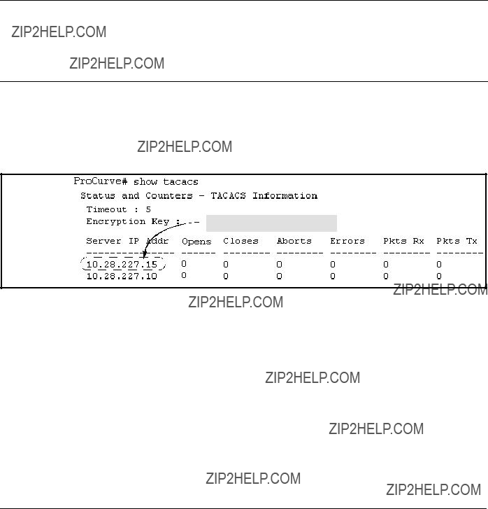
TACACS+ Authentication
Configuring TACACS+ on the Switch
Specifies the optional, global ???encryption key??? that is also assigned in the TACACS+ server(s) that the switch will access for authentication. This option is subordinate to any
For more on the encryption key, see ???Using the Encryption Key??? on page
Specifies how long the switch waits for a TACACS+ server to respond to an authentication request. If the switch does not detect a response within the timeout period, it initiates a new request to the next TACACS+ server in the list. If all TACACS+ servers in the list fail to respond within the timeout period, the switch uses either local authentication (if configured) or denies access (if none configured for local authentication).
Adding, Removing, or Changing the Priority of a TACACS+ Server.
Suppose that the switch was already configured to use TACACS+ servers at 10.28.227.10 and 10.28.227.15. In this case, 10.28.227.15 was entered first, and so is listed as the


Figure
To move the
The servers would then be listed with the new
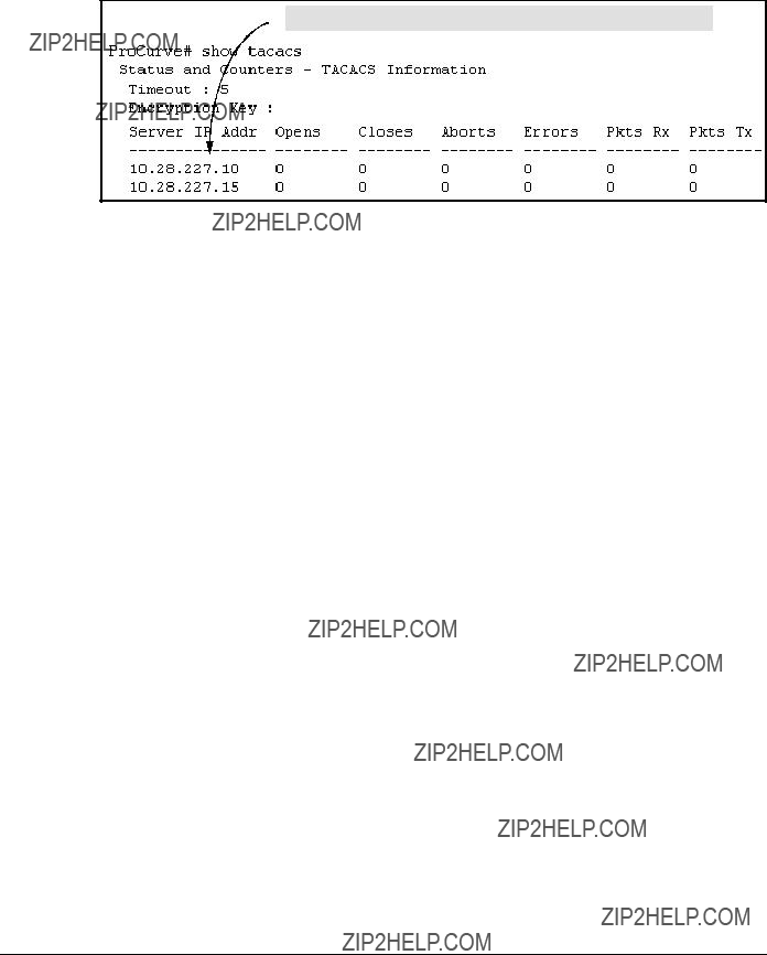
TACACS+ Authentication
Configuring TACACS+ on the Switch
 The ???10??? server is now the
Figure
To remove the 10.28.227.15 device as a TACACS+ server, you would use this command:
ProCurve(config)# no
Configuring an Encryption Key. Use an encryption key in the switch if the switch will be requesting authentication from a TACACS+ server that also uses an encryption key. (If the server expects a key, but the switch either does not provide one, or provides an incorrect key, then the authentication attempt will fail.) Use a global encryption key if the same key applies to all TACACS+ servers the switch may use for authentication attempts. Use a
To configure north01 as a global encryption key:
ProCurve(config)
To configure north01 as a
ProCurve(config)#
An encryption key can contain up to 100 characters, without spaces, and is likely to be
To delete a global encryption key from the switch, use this command:
ProCurve(config)# no

TACACS+ Authentication
Configuring TACACS+ on the Switch
To delete a
Configuring the Timeout Period. The timeout period specifies how long the switch waits for a response to an authentication request from a TACACS+ server before either sending a new request to the next server in the switch???s Server IP Address list or using the local authentication option. For example, to change the timeout period from 5 seconds (the default) to 3 seconds:
ProCurve(config)#
How Authentication Operates
General Authentication Process Using a TACACS+
Server
Authentication through a TACACS+ server operates generally as described below. For specific operating details, refer to the documentation you received with your TACACS+ server application.
Figure

TACACS+ Authentication
Configuring TACACS+ on the Switch
Using figure
1.The switch queries the
???If the switch does not receive a response from the
???If a TACACS+ server recognizes the switch, it forwards a user- name prompt to the requesting terminal via the switch.
2.When the requesting terminal responds to the prompt with a username, the switch forwards it to the TACACS+ server.
3.After the server receives the username input, the requesting terminal receives a password prompt from the server via the switch.
4.When the requesting terminal responds to the prompt with a password, the switch forwards it to the TACACS+ server and one of the following actions occurs:
???If the username/password pair received from the requesting terminal matches a username/password pair previously stored in the server, then the server passes access permission through the switch to the terminal.
???If the username/password pair entered at the requesting terminal does not match a username/password pair previously stored in the server, access is denied. In this case, the terminal is again prompted to enter a username and repeat steps 2 through 4. In the default configuration, the switch allows up to three attempts to authenticate a login session. If the requesting terminal exhausts the attempt limit without a successful TACACS+ authentication, the login session is terminated and the operator at the requesting terminal must initiate a new session before trying again.

TACACS+ Authentication
Configuring TACACS+ on the Switch
Local Authentication Process
When the switch is configured to use TACACS+, it reverts to local authentica- tion only if one of these two conditions exists:
??? ???Local??? is the authentication option for the access method being used.
??? TACACS+ is the primary authentication mode for the access method being used. However, the switch was unable to connect to any TACACS+ servers (or no servers were configured) and Local is the secondary authentication mode being used.
(For a listing of authentication options, see table
For local authentication, the switch uses the
??? If the operator at the requesting terminal correctly enters the user- name/password pair for either access level, access is granted.
??? If the username/password pair entered at the requesting terminal does not match either username/password pair previously configured

TACACS+ Authentication
Configuring TACACS+ on the Switch
TACACS+ Authentication
Configuring TACACS+ on the Switch
For example, you would use the next command to configure a global encryp- tion key in the switch to match a key entered as north40campus in two target TACACS+ servers. (That is, both servers use the same key for your switch.) Note that you do not need the server IP addresses to configure a global key in the switch:
ProCurve(config)#
Suppose that you subsequently add a third TACACS+ server (with an IP address of 10.28.227.87) that has south10campus for an encryption key. Because this key is different than the one used for the two servers in the previous example, you will need to assign a
ProCurve(config)#
With both of the above keys configured in the switch, the south10campus key overrides the north40campus key only when the switch tries to access the TACACS+ server having the 10.28.227.87 address.
Controlling Web Browser Interface
Access When Using TACACS+
Authentication
Configuring the switch for TACACS+ authentication does not affect web browser interface access. To prevent unauthorized access through the web browser interface, do one or more of the following:
???Configure local authentication (a Manager user name and password and, optionally, an Operator user name and password) on the switch.
???Configure the switch???s Authorized IP Manager feature to allow web browser access only from authorized management stations. (The Authorized IP Manager feature does not interfere with TACACS+ operation.)
???Disable web browser access to the switch by going to the System Information screen in the Menu interface and configuring the Web Agent Enabled parameter to No.
TACACS+ Authentication
Configuring TACACS+ on the Switch
Messages Related to TACACS+
Operation
The switch generates the CLI messages listed below. However, you may see other messages generated in your TACACS+ server application. For informa- tion on such messages, refer to the documentation you received with the application.
Operating Notes
???If you configure Authorized IP Managers on the switch, it is not necessary to include any devices used as TACACS+ servers in the authorized manager list. That is, authentication traffic between a TACACS+ server and the switch is not subject to Authorized IP Manager controls configured on the switch. Also, the switch does not attempt TACACS+ authentication for a management station that the Authorized IP Manager list excludes because, independent of TACACS+, the switch already denies access to such stations.

TACACS+ Authentication
Configuring TACACS+ on the Switch
???When TACACS+ is not enabled on the
5
RADIUS Authentication and Accounting
Contents
Overview . . . . . . . . . . . . . . . . . . . . . . . . . . . . . . . . . . . . . . . . . . . . . . . . . . . . . .
Terminology . . . . . . . . . . . . . . . . . . . . . . . . . . . . . . . . . . . . . . . . . . . . . . . . . . .
Switch Operating Rules for RADIUS . . . . . . . . . . . . . . . . . . . . . . . . . . . . . . .
General RADIUS Setup Procedure . . . . . . . . . . . . . . . . . . . . . . . . . . . . . . . . .
Local Authentication Process . . . . . . . . . . . . . . . . . . . . . . . . . . . . . . . . . . . .
Controlling Web Browser Interface Access When Using RADIUS
Authentication . . . . . . . . . . . . . . . . . . . . . . . . . . . . . . . . . . . . . . . . . . . . . . . .
Configuring RADIUS Accounting . . . . . . . . . . . . . . . . . . . . . . . . . . . . . . . . .
Viewing RADIUS Statistics . . . . . . . . . . . . . . . . . . . . . . . . . . . . . . . . . . . . . .
General RADIUS Statistics . . . . . . . . . . . . . . . . . . . . . . . . . . . . . . . . . . .
RADIUS Authentication Statistics . . . . . . . . . . . . . . . . . . . . . . . . . . . . .
RADIUS Accounting Statistics . . . . . . . . . . . . . . . . . . . . . . . . . . . . . . . .
Changing
Messages Related to RADIUS Operation . . . . . . . . . . . . . . . . . . . . . . . . . . .

RADIUS Authentication and Accounting
Overview
Overview
access. For information on blocking unauthorized access through the web browser interface, refer to ???Controlling Web Browser Interface Access When Using RADIUS Authentication??? on page
Accounting. RADIUS accounting on the switch collects resource consump- tion data and forwards it to the RADIUS server. This data can be used for trend analysis, capacity planning, billing, auditing, and cost analysis.

RADIUS Authentication and Accounting
Terminology
Terminology
CHAP
EAP (Extensible Authentication Protocol): A general PPP authentication protocol that supports multiple authentication mechanisms. A specific authentication mechanism is known as an EAP type, such as
Host: See RADIUS Server.
NAS (Network Access Server): In this case, a ProCurve switch configured for RADIUS security operation.
RADIUS (Remote Authentication Dial In User Service):
RADIUS Client: The device that passes user information to designated RADIUS servers.
RADIUS Host: See RADIUS server.
RADIUS Server: A server running the RADIUS application you are using on your network. This server receives user connection requests from the switch, authenticates users, and then returns all necessary information to the switch. For the ProCurve switch, a RADIUS server can also perform accounting functions. Sometimes termed a RADIUS host.
Shared Secret Key: A text value used for encrypting data in RADIUS packets. Both the RADIUS client and the RADIUS server have a copy of the key, and the key is never transmitted across the network.

RADIUS Authentication and Accounting
Switch Operating Rules for RADIUS
Switch Operating Rules for RADIUS
???You must have at least one RADIUS server accessible to the switch.
???The switch supports authentication and accounting using up to three RADIUS servers. The switch accesses the servers in the order in which they are listed by show radius (page
???You can select RADIUS as the primary authentication method for each type of access. (Only one primary and one secondary access method is allowed for each access type.)
???In the ProCurve switch, EAP RADIUS uses MD5 and TLS to encrypt a response to a challenge from a RADIUS server.

RADIUS Authentication and Accounting
General RADIUS Setup Procedure
General RADIUS Setup Procedure
Preparation:
1.Configure one to three RADIUS servers to support the switch. (That is, one primary server and one or two backups.) Refer to the documentation provided with the RADIUS server application.
2.Before configuring the switch, collect the information outlined below.
Table
???Determine the access methods (console, Telnet,
ProCurve> show authentication
Status and Counters - Authentication Information
Figure
???Determine the IP address(es) of the RADIUS server(s) you want to support the switch. (You can configure the switch for up to three RADIUS servers.)
???If you need to replace the default UDP destination port (1812) the switch uses for authentication requests to a specific RADIUS server, select it before beginning the configuration process.
???If you need to replace the default UDP destination port (1813) the switch uses for accounting requests to a specific Radius server, select it before beginning the configuration process.
???Determine whether you can use one, global encryption key for all RADIUS servers or if unique keys will be required for specific servers. With multiple RADIUS servers, if one key applies to two or more of these servers, then you can configure this key as the global encryption key. For any server whose key differs from the global key you are using, you must configure that key in the same command that you use to designate that server???s IP address to the switch.

RADIUS Authentication and Accounting
Configuring the Switch for RADIUS Authentication
???Determine an acceptable timeout period for the switch to wait for a server to respond to a request. ProCurve recommends that you begin with the default (five seconds).
???Determine how many times you want the switch to try contacting a RADIUS server before trying another RADIUS server or quitting. (This depends on how many RADIUS servers you have configured the switch to access.)
???Determine whether you want to bypass a RADIUS server that fails to respond to requests for service. To shorten authentication time, you can set a bypass period in the range of 1 to 1440 minutes for
Configuring the Switch for RADIUS
Authentication
*The web authentication option for the web browser interface is available on the 2600,

RADIUS Authentication and Accounting
Configuring the Switch for RADIUS Authentication
Outline of the Steps for Configuring RADIUS
Authentication
There are three main steps to configuring RADIUS authentication:
1.Configure RADIUS authentication for controlling access through one or more of the following
???Serial port
???Telnet
???SSH
???Web browser interface (2600,
???
2.Configure the switch for accessing one or more RADIUS servers (one primary server and up to two backup servers):
???Server IP address
???(Optional) UDP destination port for authentication requests (default: 1812; recommended)
???(Optional) UDP destination port for accounting requests (default: 1813; recommended)
???(Optional) encryption key for use during authentication sessions with a RADIUS server. This key overrides the global encryption key you can also configure on the switch, and must match the encryption key used on the specified RADIUS server. (Default: null)
3.Configure the global RADIUS parameters.
???Server Key: This key must match the encryption key used on the RADIUS servers the switch contacts for authentication and account- ing services unless you configure one or more
???Timeout Period: The timeout period the switch waits for a RADIUS
server to reply. (Default: 5 seconds; range: 1 to 15 seconds.)
???Retransmit Attempts: The number of retries when there is no server
response to a RADIUS authentication request. (Default: 3; range of 1 to 5.)

RADIUS Authentication and Accounting
Configuring the Switch for RADIUS Authentication
???Server
???Number of Login Attempts: This is an aaa authentication command. It controls how many times in one session a RADIUS client (as well as clients using other forms of access) can try to log in with the correct username and password. (Default: Three times per session.)
(For RADIUS accounting features, refer to ???Configuring RADIUS Accounting??? on page
1.Configure Authentication for the Access Methods You Want RADIUS To Protect
This section describes how to configure the switch for RADIUS authentication through the following access methods:
???Console: Either direct
???Telnet: Inbound Telnet must be enabled (the default).
???SSH: To employ RADIUS for SSH access, you must first configure the switch for SSH operation. Refer to ???Configuring Secure Shell (SSH)??? on page
???Web: Web browser interface (2600,
You can also use RADIUS for
You can configure RADIUS as the primary password authentication method for the above access methods. You will also need to select either local or none as a secondary, or backup, method. Note that for console access, if you configure radius (or tacacs) for primary authentication, you must configure local for the secondary method. This prevents the possibility of being com- pletely locked out of the switch in the event that all primary access methods fail.
RADIUS Authentication and Accounting
Configuring the Switch for RADIUS Authentication
Syntax: aaa authentication < console | telnet | ssh | web > < enable | login > < radius >
Configures RADIUS as the primary password authentication method for console, Telnet, SSH and/or the Web browser interface. (The default primary < enable | login > authentication is local.)
[< local | none >]
Provides options for secondary authentication (default: none). Note that for console access, secondary authenti- cation must be local if primary access is not local. This prevents you from being completely locked out of the switch in the event of a failure in other access methods.
For example, suppose you have already configured local passwords on the switch, but want to use RADIUS to protect primary Telnet and SSH access without allowing a secondary Telnet or SSH access option (which would be the switch???s local passwords):
ProCurve(config)# aaa authentication telnet login radius none ProCurve(config)# aaa authentication telnet enable radius none ProCurve(config)# aaa authentication ssh login radius none ProCurve(config)# aaa authentication ssh enable radius none ProCurve(config)# show authentication
Status and Counters - Authentication Information
can gain access to either the Operator or Manager level without encountering the RADIUS authentication specified for Enable Primary. Refer to ???Local Authentication Process??? on page

RADIUS Authentication and Accounting
Configuring the Switch for RADIUS Authentication
2. Configure the Switch To Access a RADIUS Server
This section describes how to configure the switch to interact with a RADIUS server for both authentication and accounting services.
Syntax: [no]
Adds a server to the RADIUS configuration or (with no) deletes a server from the configuration. You can configure up to three RADIUS server addresses. The switch uses the first server it successfully accesses. (Refer to ???Changing the RADIUS Server Access Order??? on page
Optional. Changes the UDP destination port for authenti- cation requests to the specified RADIUS server (host). If you do not use this option with the
Optional. Changes the UDP destination port for account- ing requests to the specified RADIUS server. If you do not use this option with the
[key <
Optional. Specifies an encryption key for use during authentication (or accounting) sessions with the specified server. This key must match the encryption key used on the RADIUS server. Use this command only if the specified server requires a different encryption key than configured for the global encryption key.
no
Use the no form of the command to remove the key for a specified server.
RADIUS Authentication and Accounting
Configuring the Switch for RADIUS Authentication
For example, suppose you have configured the switch as shown in figure
1.Change the encryption key for the server at 10.33.18.127 to ???source0127???.
2.Add a RADIUS server with an IP address of 10.33.18.119 and a server- specific encryption key of ???source0119???.
Figure
To make the changes listed prior to figure
Changes the key for the existing server to ???source0127???
Adds the new RADIUS server with its required ???source0119??? key.
Lists the switch???s new RADIUS server configuration. Compare this with
Figure
To change the order in which the switch accesses RADIUS servers, refer to ???Changing

RADIUS Authentication and Accounting
Configuring the Switch for RADIUS Authentication
3. Configure the Switch???s Global RADIUS Parameters
You can configure the switch for the following global RADIUS parameters:
???Number of login attempts: In a given session, specifies how many tries at entering the correct username and password pair are allowed before access is denied and the session terminated. (This is a general aaa authentication parameter and is not specific to RADIUS.)
???Global server key: The server key the switch will use for contacts with all RADIUS servers for which there is not a
???
???
???
Server timeout: Defines the time period in seconds for authentica- tion attempts. If the timeout period expires before a response is received, the attempt fails.
Server dead time: Specifies the time in minutes during which the switch avoids requesting authentication from a server that has not responded to previous requests.
Retransmit attempts: If the first attempt to contact a RADIUS server fails, specifies how many retries you want the switch to attempt on that server.

RADIUS Authentication and Accounting
Configuring the Switch for RADIUS Authentication
Syntax: aaa authentication
Specifies how many tries for entering the correct user- name and password before shutting down the session due to input errors. (Default: 3; Range: 1 - 10).
[no]
key <
Specifies the global encryption key the switch uses with servers for which the switch does not have a server- specific key assignment. This key is optional if all RADIUS server addresses configured in the switch include a
Optional. Specifies the time in minutes during which the switch will not attempt to use a RADIUS server that has not responded to an earlier authentication attempt. (Default: 0; Range: 1 - 1440 minutes)

RADIUS Authentication and Accounting
Configuring the Switch for RADIUS Authentication
For example, suppose that your switch is configured to use three RADIUS servers for authenticating access through Telnet and SSH. Two of these servers use the same encryption key. In this case your plan is to configure the switch with the following global authentication parameters:
???Allow only two tries to correctly enter username and password.
???Use the global encryption key to support the two servers that use the same key. (For this example, assume that you did not configure these two servers with a
???Use a
???Allow three seconds for request timeouts.
???Allow two retries following a request that did not receive a response.
Figure
Figure

RADIUS Authentication and Accounting
Local Authentication Process
Local Authentication Process
When the switch is configured to use RADIUS, it reverts to local authentication only if one of these two conditions exists:
??????Local??? is the authentication option for the access method being used.
???The switch has been configured to query one or more RADIUS servers for a primary authentication request, but has not received a response, and local is the configured secondary option.
For local authentication, the switch uses the
???If the operator at the requesting terminal correctly enters the user- name/password pair for either access level (Operator or Manager), access is granted on the basis of which username/password pair was used. For example, suppose you configure Telnet primary access for RADIUS and Telnet secondary access for local. If a RADIUS access attempt fails, then you can still get access to either the Operator or Manager level of the switch by entering the correct username/pass- word pair for the level you want to enter.
???If the username/password pair entered at the requesting terminal does not match either local username/password pair previously configured in the switch, access is denied. In this case, the terminal is again prompted to enter a username/password pair. In the default configu- ration, the switch allows up to three attempts. If the requesting terminal exhausts the attempt limit without a successful authentica- tion, the login session is terminated and the operator at the requesting terminal must initiate a new session before trying again.
RADIUS Authentication and Accounting
Controlling Web Browser Interface Access When Using RADIUS Authentication
Controlling Web Browser Interface Access
When Using RADIUS Authentication
To prevent unauthorized access through the web browser interface, do one or more of the following:
???For Series 2600,
???Configure local authentication (a Manager user name and password and, optionally, an Operator user name and password) on the switch.
???Configure the switch???s Authorized IP Manager feature to allow web browser access only from authorized management stations. (The Authorized IP Manager feature does not interfere with TACACS+ operation.)
???Disable web browser access to the switch.
Configuring RADIUS Accounting

RADIUS Authentication and Accounting
Configuring RADIUS Accounting
(For 802.1X information for the switch, refer to ???Configuring
???Exec accounting: Provides records holding the information listed below about login sessions (console, Telnet, and SSH) on the switch:
???System accounting: Provides records containing the information listed below when system events occur on the switch, including system reset, system boot, and enabling or disabling of system accounting.

RADIUS Authentication and Accounting
Configuring RADIUS Accounting
The switch forwards the accounting information it collects to the designated RADIUS server, where the information is formatted, stored, and managed by the server. For more information on this aspect of RADIUS accounting, refer to the documentation provided with your RADIUS server.
Operating Rules for RADIUS Accounting
???You can configure up to three types of accounting to run simultane- ously: exec, system, and network.
???RADIUS servers used for accounting are also used for authentication.
???The switch must be configured to access at least one RADIUS server.
???RADIUS servers are accessed in the order in which their IP addresses were configured in the switch. Use show radius to view the order. As long as the first server is accessible and responding to authentication requests from the switch, a second or third server will not be accessed. (For more on this topic, refer to ???Changing
???If access to a RADIUS server fails during a session, but after the client has been authenticated, the switch continues to assume the server is available to receive accounting data. Thus, if server access fails during a session, it will not receive accounting data transmitted from the switch.
Steps for Configuring RADIUS Accounting
1.Configure the switch for accessing a RADIUS server.
You can configure a list of up to three RADIUS servers (one primary, two backup). The switch operates on the assumption that a server can operate in both accounting and authentication mode. (Refer to the documentation for your RADIUS server application.)
???Use the same
???Provide the following:
???A RADIUS server IP address.
???

RADIUS Authentication and Accounting
Configuring RADIUS Accounting
???
2.Configure accounting types and the controls for sending reports to the RADIUS server.
???Accounting types: exec (page
???Trigger for sending accounting reports to a RADIUS server: At session start and stop or only at session stop
3.(Optional) Configure session blocking and interim updating options
???Updating: Periodically update the accounting data for
???Suppress accounting: Block the accounting session for any unknown user with no username access to the switch
1. Configure the Switch To Access a RADIUS Server
Before you configure the actual accounting parameters, you should first configure the switch to use a RADIUS server. This is the same as the process described on page
RADIUS Authentication and Accounting
Configuring RADIUS Accounting
Syntax: [no]
Adds a server to the RADIUS configuration or (with no) deletes a server from the configuration.
Optional. Changes the UDP destination port for accounting requests to the specified RADIUS server. If you do not use this option, the switch automatically assigns the default accounting port number. (Default: 1813)
[key <
Optional. Specifies an encryption key for use during accounting or authentication sessions with the speci- fied server. This key must match the encryption key used on the RADIUS server. Use this command only if the specified server requires a different encryption key than configured for the global encryption key.
(For a more complete description of the
For example, suppose you want to the switch to use the RADIUS server described below for both authentication and accounting purposes.
???IP address: 10.33.18.151
???A
For this example, assume that all other RADIUS authentication parameters for accessing this server are acceptable at their default settings, and that RADIUS is already configured as an authentication method for one or more types of access to the switch (Telnet, Console, etc.).

RADIUS Authentication and Accounting
Configuring RADIUS Accounting
Because the
Figure
The
2.Configure Accounting Types and the Controls for Sending Reports to the RADIUS Server
Select the Accounting Type(s):
???Exec: Use exec if you want to collect accounting information on login sessions on the switch via the console, Telnet, or SSH. (See also ???Accounting??? on page
???System: Use system if you want to collect accounting data when:
???A system boot or reload occurs
???System accounting is turned on or off
Note that there is no time span associated with using the system option. It simply causes the switch to transmit whatever accounting data it currently has when one of the above events occurs.
???Network: Use Network if you want to collect accounting information on 802.1X
Determine how you want the switch to send accounting data to a RADIUS server:
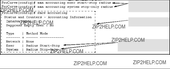
RADIUS Authentication and Accounting
Configuring RADIUS Accounting
???
???Send a start record accounting notice at the beginning of the account- ing session and a stop record notice at the end of the session. Both notices include the latest data the switch has collected for the requested accounting type (Network, Exec, or System).
???Do not wait for an acknowledgement.
The system option (page
???
???Send a stop record accounting notice at the end of the accounting session. The notice includes the latest data the switch has collected for the requested accounting type (Network, Exec, or System).
???Do not wait for an acknowledgment.
The system option (page
Syntax: [no] aaa accounting < exec | network | system > <
Configures RADIUS accounting type and how data will be sent to the RADIUS server.
For example, to configure RADIUS accounting on the switch with
Configures exec and system accounting and controls.
Summarizes the switch???s accounting configuration.
Exec and System accounting are active. (Assumes the switch is configured to access a reachable
Figure

RADIUS Authentication and Accounting
Configuring RADIUS Accounting
3. (Optional) Configure Session Blocking and Interim
Updating Options
These optional parameters give you additional control over accounting data.
???Updates: In addition to using a
???Suppress: The switch can suppress accounting for an unknown user having no username.
Syntax: [no] aaa accounting update periodic < 1 - 525600 >
Sets the accounting update period for all accounting ses- sions on the switch. (The no form disables the update function and resets the value to zero.) (Default: zero; dis- abled)
Syntax: [no] aaa accounting suppress
Disables accounting for unknown users having no user- name. (Default: suppression disabled)
To continue the example in figure
???Send updates every 10 minutes on
???Block accounting for unknown users (no username).

 ??? Update Period
 ??? Suppress Unknown User
Figure

RADIUS Authentication and Accounting
Viewing RADIUS Statistics
Viewing RADIUS Statistics
General RADIUS Statistics
Syntax: show radius [host <
Shows general RADIUS configuration, including the server IP addresses. Optional form shows data for a specific RADIUS host. To use show radius, the server???s IP address must be configured in the switch, which. requires prior use of the
Figure
Figure

RADIUS Authentication and Accounting
Viewing RADIUS Statistics
Table
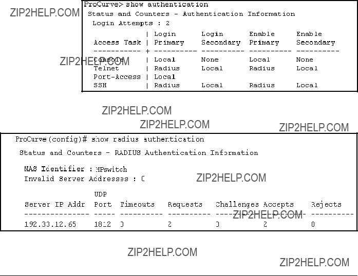
RADIUS Authentication and Accounting
Viewing RADIUS Statistics
RADIUS Authentication Statistics
Syntax: show authentication
Displays the primary and secondary authentication meth- ods configured for the Console, Telnet,
show radius authentication
Displays NAS identifier and data on the configured RADIUS server and the switch???s interactions with this server. (Requires prior use of the
Figure
Information from the Show Authentication Command
Figure

RADIUS Authentication and Accounting
Viewing RADIUS Statistics
RADIUS Accounting Statistics
Syntax: show accounting
Lists configured accounting interval, ???Empty User??? suppres- sion status, accounting types, methods, and modes.
show radius accounting
Lists accounting statistics for the RADIUS server(s) config- ured in the switch (using the
show accounting sessions
Lists the accounting sessions currently active on the switch.
Figure
Figure

RADIUS Authentication and Accounting
Changing
Figure
Changing
The switch tries to access RADIUS servers according to the order in which their IP addresses are listed by the show radius command. Also, when you add a new server IP address, it is placed in the highest empty position in the list.
Adding or deleting a RADIUS server IP address leaves an empty position, but does not change the position of any other server addresses in the list. For example if you initially configure three server addresses, they are listed in the order in which you entered them. However, if you subsequently remove the second server address in the list and add a new server address, the new address will be placed second in the list.
Thus, to move a server address up in the list, you must delete it from the list, ensure that the position to which you want to move it is vacant, and then re- enter it. For example, suppose you have already configured the following three RADIUS server IP addresses in the switch:
RADIUS server IP addresses listed in the order in which the switch will try to access them. In this case, the server at IP address 10.10.10.1 is first.
Note: If the switch successfully accesses the first server, it does not try to access any other servers in the list, even if the client is denied access by the first server.
Figure

RADIUS Authentication and Accounting
Changing
To exchange the positions of the addresses so that the server at 10.10.10.003 will be the first choice and the server at 10.10.10.001 will be the last, you would do the following:
1.Delete 10.10.10.003 from the list. This opens the third (lowest) position in the list.
2.Delete 10.10.10.001 from the list. This opens the first (highest) position in the list.
3.
4.
Removes the ???003??? and ???001??? addresses from the RADIUS server list.
Inserts the ???003??? address in the first position in the RADIUS server list, and inserts the ???001??? address in the last position in the list.
Shows the new order in which the switch searches for a RADIUS server.
Figure
RADIUS Authentication and Accounting
Messages Related to RADIUS Operation
Messages Related to RADIUS Operation
Can???t reach RADIUS server < x.x.x.x >.
A designated RADIUS server is not responding to an authentication request. Try pinging the server to determine whether it is accessible to the switch. If the server is accessible, then verify that the switch is using the correct encryption key and that the server is correctly configured to receive an authentication request from the switch.

RADIUS Authentication and Accounting
Messages Related to RADIUS Operation
??? This page is intentionally unused. ???

6
Configuring Secure Shell (SSH)
Contents
Contents . . . . . . . . . . . . . . . . . . . . . . . . . . . . . . . . . . . . . . . . . . . . . . . . . . . . . . .
Overview . . . . . . . . . . . . . . . . . . . . . . . . . . . . . . . . . . . . . . . . . . . . . . . . . . . . . .
Terminology . . . . . . . . . . . . . . . . . . . . . . . . . . . . . . . . . . . . . . . . . . . . . . . . . . .
Prerequisite for Using SSH . . . . . . . . . . . . . . . . . . . . . . . . . . . . . . . . . . . . . . .
Public Key Formats . . . . . . . . . . . . . . . . . . . . . . . . . . . . . . . . . . . . . . . . . . . . .
Steps for Configuring and Using SSH for Switch and
Client Authentication . . . . . . . . . . . . . . . . . . . . . . . . . . . . . . . . . . . . . . . . . . . .
General Operating Rules and Notes . . . . . . . . . . . . . . . . . . . . . . . . . . . . . . . .
Configuring the Switch for SSH Operation . . . . . . . . . . . . . . . . . . . . . . . . . .
4. Enable SSH on the Switch and Anticipate SSH Client
Contact Behavior . . . . . . . . . . . . . . . . . . . . . . . . . . . . . . . . . . . . . . . . . . .
Further Information on SSH Client
Messages Related to SSH Operation . . . . . . . . . . . . . . . . . . . . . . . . . . . . . .

Configuring Secure Shell (SSH)
Overview
Overview
The ProCurve switches covered in this guide use Secure Shell version 1 or 2 (SSHv1 or SSHv2) to provide remote access to management functions on the switches via encrypted paths between the switch and management station clients capable of SSH operation.
SSH provides
???Client
???Switch SSH and user password authentication
Client Public Key Authentication (Login/Operator Level) with User
Password Authentication (Enable/Manager Level). This option uses one or more public keys (from clients) that must be stored on the switch. Only a client with a private key that matches a stored public key can gain access to the switch. (The same private key can be stored on one or more clients.)
ProCurve
Switch
(SSH
Server)

 1.
1.


options:
???Local
???TACACS+
???RADIUS
???None
SSH
Client
Work-
Station
Figure
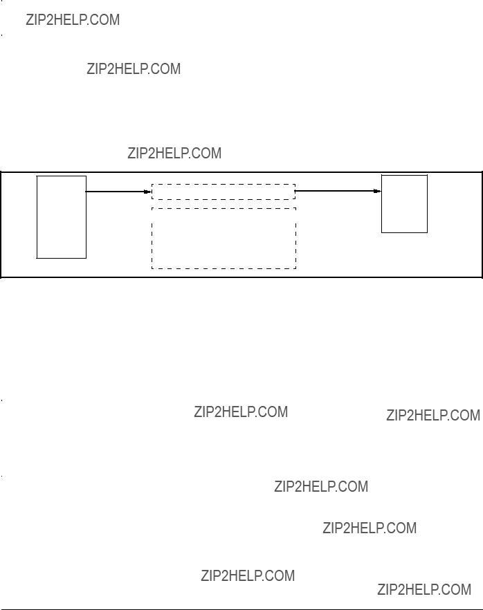
ProCurve
Switch
(SSH
Server)
1.

 2.
2.  enable password authentication)
options:
???Local
???TACACS+
SSH
Client
Work-
Station
Figure
SSH on the ProCurve switches covered in this guide supports these data encryption methods:

Configuring Secure Shell (SSH)
Terminology
Terminology
???SSH Server: A ProCurve switch with SSH enabled.
???Key Pair: A pair of keys generated by the switch or an SSH client application. Each pair includes a public key, that can be read by anyone and a private key, that is held internally in the switch or by a client.
???PEM (Privacy Enhanced Mode): Refers to an
???Private Key: An internally generated key used in the authentication process. A private key generated by the switch is not accessible for viewing or copying. A private key generated by an SSH client applica- tion is typically stored in a file on the client device and, together with its public key counterpart, can be copied and stored on multiple devices.
???Public Key: An internally generated counterpart to a private key. A device???s public key is used to authenticate the device to other devices.
???Enable Level: Manager privileges on the switch.
???Login Level: Operator privileges on the switch.
???Local password or username: A
???SSH Enabled: (1) A public/private key pair has been generated on the switch (crypto key generate ssh [rsa]) and (2) SSH is enabled (ip ssh). (You can generate a key pair without enabling SSH, but you cannot enable SSH without first generating a key pair. See ???2. Generate the Switch???s Public and Private Key Pair??? on page

Configuring Secure Shell (SSH)
Prerequisite for Using SSH
Prerequisite for Using SSH
Before using the switch as an SSH server, you must install a publicly or commercially available SSH client application on the computer(s) you use for management access to the switch. If you want client
Public Key Formats
Any client application you use for client
Comment describing public key identity.
Beginning of actual SSHv2 public key in
Figure
Figure

Configuring Secure Shell (SSH)
Steps for Configuring and Using SSH for Switch and Client Authentication
Steps for Configuring and Using SSH for
Switch and Client Authentication
For
1 For ssh login
The general steps for configuring SSH include:
A.Client Preparation
1.Install an SSH client application on a management station you want to use for access to the switch. (Refer to the documentation provided with your SSH client application.)
2.
a.Either generate a public/private key pair on the client computer (if your client application allows) or import a client key pair that you have generated using another SSH application.
b.Copy the client public key into an ASCII file on a TFTP server accessible to the switch and download the client public key file to the switch. (The client public key file can hold up to ten client keys.) This topic is covered under ???To Create a

Configuring Secure Shell (SSH)
Steps for Configuring and Using SSH for Switch and Client Authentication
B.Switch Preparation
1.Assign a login (Operator) and enable (Manager) password on the switch (page
2.Generate a public/private key pair on the switch (page
You need to do this only once. The key remains in the switch even if you reset the switch to its
3.Copy the switch???s public key to the SSH clients you want to access the switch (page
4.Enable SSH on the switch (page
5.Configure the primary and secondary authentication methods you want the switch to use. In all cases, the switch will use its
???SSH Login (Operator) options:
???Option A:
Primary: Local, TACACS+, or RADIUS password
Secondary: Local password or none
??? Option B:
Primary: Client
Secondary: Local password or none
Note that if you want the switch to perform client
??? SSH Enable (Manager) options:
Primary: Local, TACACS+, or RADIUS
Secondary: Local password or none
6.Use your SSH client to access the switch using the switch???s IP address or DNS name (if allowed by your SSH client application). Refer to the documentation provided with the client application.

Configuring Secure Shell (SSH)
General Operating Rules and Notes
General Operating Rules and Notes
???Public keys generated on an SSH client must be exportable to the switch. The switch can only store ten keys client key pairs.
???The switch???s own public/private key pair and the (optional) client public key file are stored in the switch???s flash memory and are not affected by reboots or the erase
???Once you generate a key pair on the switch you should avoid re- generating the key pair without a compelling reason. Otherwise, you will have to
???On ProCurve switches that support stacking, when stacking is enabled, SSH provides security only between an SSH client and the stack manager. Communications between the stack commander and stack members is not secure.
???The switch does not support outbound SSH sessions. Thus, if you Telnet from an
Configuring Secure Shell (SSH)
Configuring the Switch for SSH Operation
Configuring the Switch for SSH
Operation
1. Assign Local Login (Operator) and Enable (Manager)
Password
At a minimum, ProCurve recommends that you always assign at least a Manager password to the switch. Otherwise, under some circumstances, anyone with Telnet, web, or serial port access could modify the switch???s configuration.
To Configure Local Passwords. You can configure both the Operator and Manager password with one command.
Syntax:password < manager | operator | all >

Configuring Secure Shell (SSH)
Configuring the Switch for SSH Operation
Figure
2. Generate the Switch???s Public and Private Key Pair
You must generate a public and private host key pair on the switch. The switch uses this key pair, along with a dynamically generated session key pair to negotiate an encryption method and session with an SSH client trying to connect to the switch.
The host key pair is stored in the switch???s flash memory, and only the public key in this pair is readable. The public key should be added to a "known hosts" file (for example, $HOME/.ssh/known_hosts on UNIX systems) on the SSH clients which should have access to the switch. Some SSH client appli- cations automatically add the switch???s public key to a "known hosts" file. Other SSH applications require you to manually create a known hosts file and place the switch???s public key in the file. (Refer to the documentation for your SSH client application.)
(The session key pair mentioned above is not visible on the switch. It is a temporary, internally generated pair used for a particular switch/client ses- sion, and then discarded.)


Configuring Secure Shell (SSH)
Configuring the Switch for SSH Operation
For example, to generate and display a new key:
Host Public
Key for the
Switch
Version 1 and Version 2 Views
of Same Host Public Key
Figure
The 'show crypto
3. Provide the Switch???s Public Key to Clients
When an SSH client contacts the switch for the first time, the client will challenge the connection unless you have already copied the key into the client???s "known host" file. Copying the switch???s key in this way reduces the chance that an unauthorized device can pose as the switch to learn your access passwords. The most secure way to acquire the switch???s public key for

Configuring Secure Shell (SSH)
Configuring the Switch for SSH Operation
distribution to clients is to use a direct, serial connection between the switch and a management device (laptop, PC, or UNIX workstation), as described below.
The public key generated by the switch consists of three parts, separated by one blank space each:
896 35 427199470766077426366625060579924214851527933248752021855126493
2934075407047828604329304580321402733049991670046707698543529734853020
0176777055355544556880992231580238056056245444224389955500310200336191
3610469786020092436232649374294060627777506601747146563337525446401
Figure
(The generated public key on the switch is always 896 bits.)
With a direct serial connection from a management station to the switch:
1.Use a terminal application such as HyperTerminal to display the switch???s public key with the show crypto
2.Bring up the SSH client???s "known host" file in a text editor such as Notepad as straight ASCII text, and copy the switch???s public key into the file.
3.Ensure that there are no changes in breaks in the text string. (A public key must be an unbroken ASCII string. Line breaks are not allowed Changes in the line breaks will corrupt the Key.) For example, if you are using Windows?? Notepad, ensure that Word Wrap (in the Edit menu) is disabled, and that the key text appears on a single line.
Figure
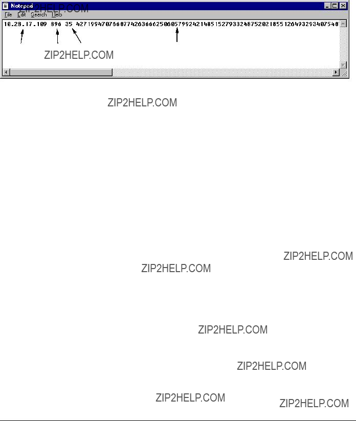
Configuring Secure Shell (SSH)
Configuring the Switch for SSH Operation
4.Add any data required by your SSH client application. For example Before saving the key to an SSH client???s "known hosts" file you may have to insert the switch???s IP address:
Figure
For more on this topic, refer to the documentation provided with your SSH client application.
Displaying the Public Key. The switch provides three options for display- ing its public key. This is helpful if you need to visually verify that the public key the switch is using for authenticating itself to a client matches the copy of this key in the client???s "known hosts" file:
???
???Phonetic hash: Outputs the key as a relatively short series of alpha- betic character groups. Requires a client ability to convert the key to this format.
???Hexadecimal hash: Outputs the key as a relatively short series of hexadecimal numbers. Requires a parallel client ability.
For example, on the switch, you would generate the phonetic and hexadecimal versions of the switch???s public key in figure

Configuring Secure Shell (SSH)
Configuring the Switch for SSH Operation
Figure
The two commands shown in figure
4. Enable SSH on the Switch and Anticipate SSH Client Contact Behavior
The ip ssh command enables or disables SSH on the switch and modifies parameters the switch uses for transactions with clients. After you enable SSH, the switch can authenticate itself to SSH clients.
When configured for SSH, the switch uses its host
Refer to ???5. Configure the Switch for SSH Authentication??? on page
Configuring Secure Shell (SSH)
Configuring the Switch for SSH Operation
SSH Client Contact Behavior. At the first contact between the switch and an SSH client, if you have not copied the switch???s public key into the client, your client???s first connection to the switch will question the connection and, for security reasons, give you the option of accepting or refusing. As long as you are confident that an unauthorized device is not using the switch???s IP address in an attempt to gain access to your data or network, you can accept the connection. (As a more secure alternative, you can directly connect the client to the switch???s serial port and copy the switch???s public key into the client. See the following Note.)
To enable SSH on the switch.
1.Generate a public/private key pair if you have not already done so. (Refer to ???2. Generate the Switch???s Public and Private Key Pair??? on page
2.Execute the ip ssh command.
To disable SSH on the switch, do either of the following:
???Execute no ip ssh.
???Zeroize the switch???s existing key pair. (page
Syntax: [no] ip ssh
Enables or disables SSH on the switch.
The size of the internal, automatically generated key the switch uses for negotiations with an SSH client. A larger key provides greater security; a smaller key results in faster authentication (default: 512 bits).
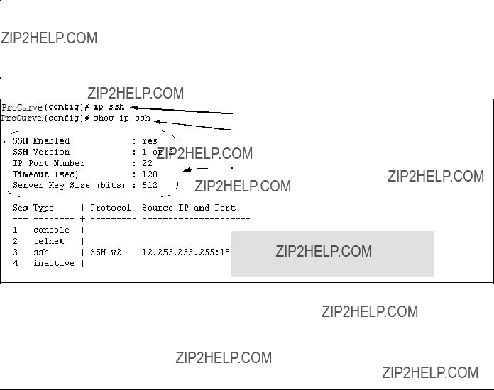
Configuring Secure Shell (SSH)
Configuring the Switch for SSH Operation
[port <
The TCP port number for SSH connections (default: 22). Important: See ???Note on Port Number??? on page
[timeout < 5 - 120 >]
The SSH login timeout value (default: 120 seconds).
[version <1 | 2 |
With SSH running, the switch allows one console session and up to three other sessions (SSH and/or Telnet). Web browser sessions are
also allowed, but do not appear in the show ip ssh
Figure

Configuring Secure Shell (SSH)
Configuring the Switch for SSH Operation
Caution
Note
Protect your private key file from access by anyone other than yourself. If someone can access your private key file, they can then penetrate SSH security on the switch by appearing to be you.
SSH does not protect the switch from unauthorized access via the web interface, Telnet, SNMP, or the serial port. While web and Telnet access can be restricted by the use of passwords local to the switch, if you are unsure of the security this provides, you may want to disable
5. Configure the Switch for SSH Authentication
Note that all methods in this section result in authentication of the switch???s public key by an SSH client. However, only Option B (page
ProCurve recommends that you always assign a
Also, if you configure only an Operator password, entering the Operator password through telnet, web, SSH or serial port access enables full manager privileges. See ???1. Assign Local Login (Operator) and Enable (Manager) Password??? on page
Option A: Configuring SSH Access for
Authentication. When configured with this option, the switch uses its pub- lic key to authenticate itself to a client, but uses only passwords for client authentication.
Configuring Secure Shell (SSH)
Configuring the Switch for SSH Operation
Syntax: aaa authentication ssh login < local | tacacs | radius >[< local | none >]
Configures a password method for the primary and second- ary login (Operator) access. If you do not specify a secondary method, it defaults to none.
If the primary method is local, the secondary method is always none, which may or may not be specified.
aaa authentication ssh enable < local | tacacs | radius>[< local | none >]
Configures a password method for the primary and second- ary enable (Manager) access. If you do not specify a second- ary method, it defaults to none.
If the primary method is local, the secondary method is always none, which may or may not be specified.
Option B: Configuring the Switch for Client
Authentication. When configured with this option, the switch uses its pub- lic key to authenticate itself to a client, but the client must also provide a client
This means that before you can use this option, you must:
1.Create a key pair on an SSH client.
2.Copy the client???s public key into a
3.Copy the
(For more on these topics, refer to ???Further Information on SSH Client Public- Key Authentication??? on page
With steps 1 - 3, above, completed and SSH properly configured on the switch, if an SSH client contacts the switch, login authentication automatically occurs using the switch and client

Configuring Secure Shell (SSH)
Configuring the Switch for SSH Operation
Syntax: copy tftp
Copies a public key file into the switch.
aaa authentication ssh login
Configures the switch to authenticate a client
When the primary method is
Syntax: aaa authentication ssh enable < local | tacacs | radius > < local | none >
Configures a password method for the primary and second- ary enable (Manager) access. If you do not specify an optional secondary method, it defaults to none.
If the primary method is local, the secondary method is always none, which may or may not be specified.
For example, assume that you have a client
Copies a public key file named
Configures the primary and secondary password methods for Manager (enable) access. (Becomes available after SSH access is granted
Figure

Configuring Secure Shell (SSH)
Further Information on SSH Client
Figure
Figure
6. Use an SSH Client To Access the Switch
Test the SSH configuration on the switch to ensure that you have achieved the level of SSH operation you want for the switch. If you have problems, refer to
Further Information on SSH Client
The section titled ???5. Configure the Switch for SSH Authentication??? on page

Configuring Secure Shell (SSH)
Further Information on SSH Client
When configured for SSH operation, the switch automatically attempts to use its own host
SSH clients that support client
(Note that even without using client
If you enable client
1.The client sends its public key to the switch with a request for authenti- cation.
2.The switch compares the client???s public key to those stored in the switch???s
3.If there is not a match, and you have not configured the switch to accept
alogin password as a secondary authentication method, the switch denies SSH access to the client.
4.If there is a match, the switch:
a.Generates a random sequence of bytes.
b.Uses the client???s public key to encrypt this sequence.
c.Send these encrypted bytes to the client.
5.The client uses its private key to decrypt the byte sequence.
6.The client then:
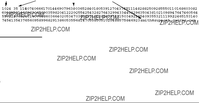
Configuring Secure Shell (SSH)
Further Information on SSH Client
a.Combines the decrypted byte sequence with specific session data.
b.Uses a secure hash algorithm to create a hash version of this informa- tion.
c.Returns the hash version to the switch.
7.The switch computes its own hash version of the data in step 6 and compares it to the client???s hash version. If they match, then the client is authenticated. Otherwise, the client is denied access.
Using client
1.Generate a public/private key pair for each client you want to have SSH access to the switch. This can be a separate key for each client or the same key copied to several clients.
2.Copy the public key for each client into a
3.Use copy tftp to copy the
4.Use the aaa authentication ssh command to enable client
To Create a
Figure

Configuring Secure Shell (SSH)
Further Information on SSH Client
1.Use your SSH client application to create a public/private key pair. Refer to the documentation provided with your SSH client application for details. The switch supports the following
2.Copy the client???s public key into a text file (filename.txt). (For example, you can use the Notepad editor included with the Microsoft?? Windows?? software. If you want several clients to use client
3.Copy the
Copying a
???One or more
???A copy of each client public key (up to ten) stored in a single text file or individual on a TFTP server to which the switch has access. Terminate all client
Note on Public The actual content of a public key entry in a public key file is determined by Keysthe SSH client application generating the key. (Although you can manually add or edit any comments the client application adds to the end of the key, such
as the smith@fellow at the end of the key in figure
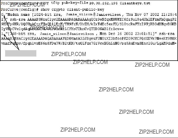
Configuring Secure Shell (SSH)
Further Information on SSH Client
Syntax: copy tftp
Copies a public key file from a TFTP server into flash memory in the switch.
show crypto
Displays the client public key(s) in the switch???s current
The babble option converts the key data to phonetic hashes that are easier for visual comparisons.
The fingerprint option converts the key data to phonetic hashes that are for the same purpose.
For example, if you wanted to copy a client
Key Index Number
Figure
Replacing or Clearing the Public Key File. The client
???You can remove the existing client
Syntax:clear crypto
Deletes the
Syntax:clear crypto
Deletes the entry with an index of 3 from the
Configuring Secure Shell (SSH)
Further Information on SSH Client
Enabling Client
??? If an SSH client???s public key matches the switch???s
??? If an SSH client???s public key does not have a match in the switch???s
Syntax: aaa authentication ssh login
Allows SSH client access only if the switch detects a match between the client???s public key and an entry in the client-
aaa authentication ssh login

Configuring Secure Shell (SSH)
Messages Related to SSH Operation
Messages Related to SSH Operation
Error: Requested keyfile does not exist. The client key does not exist in the switch. Use copy tftp to download the key from a TFTP server.

Configuring Secure Shell (SSH)
Messages Related to SSH Operation
7
Configuring Secure Socket Layer (SSL)
Contents
Overview . . . . . . . . . . . . . . . . . . . . . . . . . . . . . . . . . . . . . . . . . . . . . . . . . . . . . .
Steps for Configuring and Using SSL for Switch
and Client Authentication . . . . . . . . . . . . . . . . . . . . . . . . . . . . . . . . . . . . . . . .
3. Enable SSL on the Switch and Anticipate SSL Browser Contact Behavior . . . . . . . . . . . . . . . . . . . . . . . . . . . . . . . . . . . . . . . . . . . . . . . . . .
Common Errors in SSL Setup . . . . . . . . . . . . . . . . . . . . . . . . . . . . . . . . . . . .
Configuring Secure Socket Layer (SSL)
Overview
Overview
Note
Note
The ProCurve switches covered by this manual use Secure Socket Layer Version 3 (SSLv3) and support for Transport Layer Security(TLSv1) to provide remote web access to the switches via encrypted paths between the switch and management station clients capable of SSL/TLS operation.
ProCurve switches use SSL and TLS for all secure web transactions, and all references to SSL mean using one of these algorithms unless otherwise noted
SSL provides all the web functions but, unlike standard web access, SSL provides encrypted, authenticated transactions. The authentication type includes server certificate authentication with user password authentication.
SSL in ProCurve switches is based on the OpenSSL software toolkit. For more information on OpenSSL, visit http://www.openssl.com.
Server Certificate authentication with User Password
Authentication . This option is a subset of full certificate authentication of the user and host. It occurs only if the switch has SSL enabled. As in figure 7- 1, the switch authenticates itself to SSL enabled web browser. Users on SSL browser then authenticate themselves to the switch (operator and/or manger levels) by providing passwords stored locally on the switch or on a TACACS+ or RADIUS server. However, the client does not use a certificate to authenti- cate itself to the switch.

Configuring Secure Socket Layer (SSL)
Terminology
ProCurve
Switch
1.
SSL Client
Browser
???Local
???TACACS+
???RADIUS
Figure
Terminology
???SSL Server: A ProCurve switch with SSL enabled.
???Key Pair: Public/private pair of RSA keys generated by switch, of which public portion makes up part of server host certificate and private portion is stored in switch flash (not user accessible).
???Digital Certificate: A certificate is an electronic ???passport??? that is used to establish the credentials of the subject to which the certificate was issued. Information contained within the certificate includes: name of the subject, serial number, date of validity, subject's public key, and the digital signature of the authority who issued the certifi- cate. Certificates on Procurve switches conform to the X.509v3 stan- dard, which defines the format of the certificate.

Configuring Secure Socket Layer (SSL)
Terminology
???
???
???Root Certificate: A trusted certificate used by certificate authorities to sign certificates
???Manager Level: Manager privileges on the switch.
???Operator Level: Operator privileges on the switch.
???Local password or username: A
???SSL Enabled: (1) A certificate key pair has been generated on the
switch (web interface or CLI command: crypto key generate cert [key size] (2) A certificate been generated on the switch (web interface or CLI command: crypto

Note:
Configuring Secure Socket Layer (SSL)
Prerequisite for Using SSL
Prerequisite for Using SSL
Before using the switch as an SSL server, you must install a publicly or commercially available SSL enabled web browser application on the com- puter(s) you use for management access to the switch.
Steps for Configuring and Using SSL for Switch and Client Authentication
The general steps for configuring SSL include:
A.Client Preparation
1.Install an SSL capable browser application on a management station you want to use for access to the switch. (Refer to the documentation provided with your browser.)
The latest versions of Microsoft Internet Explorer and Netscape web browser support SSL and TLS functionality. See the browser documentation for addi- tional details
B.Switch Preparation
1.Assign a login (Operator) and enable (Manager) password on the switch (page
2.Generate a host certificate on the switch (page
i.Generate certificate key pair
ii.Generate host certificate
You need to do this only once. The switch's own public/private certificate key pair and certificate are stored in the switch's flash memory and are not affected by reboots or the erase
3.Enable SSL on the switch (page
4.Use your SSL enabled browser to access the switch using the switch???s IP address or DNS name (if allowed by your browser). Refer to the documentation provided with the browser application.

Configuring Secure Socket Layer (SSL)
General Operating Rules and Notes
General Operating Rules and Notes
???Once you generate a certificate on the switch you should avoid re- generating the certificate without a compelling reason. Otherwise, you will have to
???The switch's own public/private certificate key pair and certificate are stored in the switch's flash memory and are not affected by reboots or the erase
???The public/private certificate key pair is not be confused with the SSH public/private key pair. The certificate key pair and the SSH key pair are independent of each other, which means a switch can have two keys pairs stored in flash
???On ProCurve switches that support stacking, when stacking is enabled, SSL provides security only between an SSL client and the stack manager. Communications between the stack commander and stack members is not secure.

Configuring Secure Socket Layer (SSL)
Configuring the Switch for SSL Operation
Configuring the Switch for SSL
Operation
1.Assign Local Login (Operator) and Enable (Manager) Password
At a minimum, ProCurve recommends that you always assign at least a Manager password to the switch. Otherwise, under some circumstances, anyone with Telnet, web, or serial port access could modify the switch???s configuration.
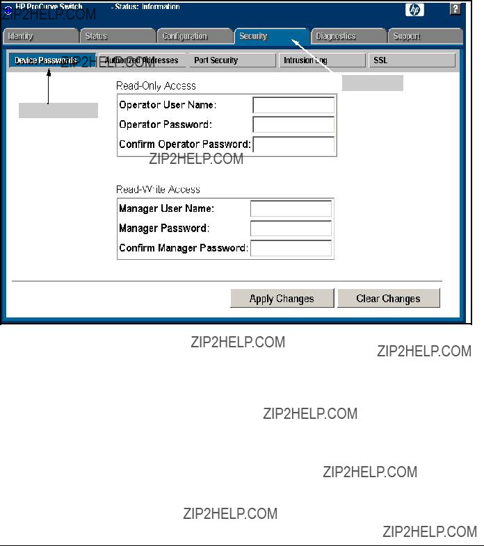
Configuring Secure Socket Layer (SSL)
Configuring the Switch for SSL Operation
Using the web browser interface To Configure Local Passwords. You can configure both the Operator and Manager password on one screen. To access the web browser interface refer to the chapter titled ???Using the Web Browser Interface??? in the Management and Configuration Guide for your switch.
Security Tab
Password Button
Figure
1.Proceed to the security tab and select device passwords button.
2.Click in the appropriate box in the Device Passwords window and enter user names and passwords. You will be required to repeat the password strings in the confirmation boxes.
Both the user names and passwords can be up to 16 printable ASCII characters.
3.Click on Apply Changes button to activate the user names and pass- words.

Configuring Secure Socket Layer (SSL)
Configuring the Switch for SSL Operation

Configuring Secure Socket Layer (SSL)
Configuring the Switch for SSL Operation
Note:
Note:
To Generate or Erase the Switch???s Server Certificate with the
CLI
Because the host certificate is stored in flash instead of the
CLI commands used to generate a Server Host Certificate.
Syntax: crypto key generate cert [rsa] < 512 | 768 |1024 >
Generates a key pair for use in the certificate.
crypto key zeroize cert
Erases the switch???s certificate key and disables SSL opera- tion.
crypto
Generates a self signed host certificate for the switch. If a switch certificate already exists, replaces it with a new certificate. (See the Note on page
crypto
Erases the switch???s host certificate and disables SSL opera- tion.
To generate a host certificate from the CLI:
i.Generate a certificate key pair. This is done with the crypto key generate cert command. The default key size is 512.
If a certificate key pair is already present in the switch, it is not necessary to generate a new key pair when generating a new certificate. The existing key pair may be
ii.Generate a new
When generating a
Configuring Secure Socket Layer (SSL)
Configuring the Switch for SSL Operation
Comments on Certificate Fields.
There are a number arguments used in the generation of a server certificate. table
Table
For example, to generate a key and a new host certificate:
Generate New Key
Generate New Certificate
Enter certificate Arguments
Figure

Configuring Secure Socket Layer (SSL)
Configuring the Switch for SSL Operation
Figure

Configuring Secure Socket Layer (SSL)
Configuring the Switch for SSL Operation
Generate a
You can configure SSL from the web browser interface. For more information on how to access the web browser interface, refer to the chapter titled ???Using the Web Browser Interface??? in the Management and Configuration Guide for your switch.
To generate a self signed host certificate from the web browser interface:
i.Select the Security tab then the [SSL] button. The SSL configuration screen is divided into two halves. The left half is used for creating a new certificate key pair and
ii.Select the Create Certificate/Certificate Request radio button.
iii.Select
iv.Select the RSA Key Size desired. If you want to
v.Fill in the remaining certificate arguments. (Refer to ???Comments on Certificate Fields.??? on page
vi.Click on the [Apply Changes] button to generate new certificate and key, if selected.

Configuring Secure Socket Layer (SSL)
Configuring the Switch for SSL Operation
For example, to generate a new host certificate via the web browsers inter- face:
Security Tab
SSL button
Create Certificate Button
Certificate Type Box
Key Size Selection
Certificate Arguments
Figure
To view the current host certificate in the web browser interface:
1.Proceed to the Security tab
2.Then the [SSL] button

Configuring Secure Socket Layer (SSL)
Configuring the Switch for SSL Operation
Current SSL Host Certificate
Figure
Generate a
Browser Interface
This section describes how to install a

Configuring Secure Socket Layer (SSL)
Configuring the Switch for SSL Operation
The installation of a
To generate a certificate request from the web browser interface:
i.Select the Security tab, then the [SSL] button.
ii.Select the Create Certificate/Certificate Request radio button.
iii.Select Create CA Request from the Certificate Type
iv.Select the key size from the RSA Key Size
v.Fill in the remaining certificate arguments. (Refer to ???Comments on Certificate Fields.??? on page
vi.Click on [Apply Changes] to create the certificate request. A new web browser page appears, consisting of two text boxes. The switch uses the upper text box for the certificate request text. The lower text box appears empty. You will use it for pasting in the certificate reply after you receive it from the certificate authority. (This authority must return a
vii.After the certificate authority processes your request and sends you a certificate reply (that is, an installable certificate), copy and paste the certificate into the lower text box.
viii.Click on the [Apply Changes] button to install the certificate.

Configuring Secure Socket Layer (SSL)
Configuring the Switch for SSL Operation
Certificate Request
Certificate Request Reply
MIICZDCCAc2gAwIBAgIDMA0XMA0GCSqGSIb3DQEBBAUAMIGHMQswCQYDVQQGEwJa
QTEiMCAGA1UECBMZRk9SIFRFU1RJTkcgUFVSUE9TRVMgT05MWTEdMBsGA1UEChMU
VGhhd3RlIENlcnRpZmljYXRpb24xFzAVBgNVBAsTDlRFU1QgVEVTVCBURVNUMRww
GgYDVQQDExNUaGF3dGUgVGVzdCBDQSBSb290MB4XDTAyMTEyMjIyNTIxN1oXDTAy
MTIxMzIyNTIxN1owgYQxCzAJBgNVBAYTAlpBMRUwEwYDVQQIEwxXZXN0ZXJuIENh
cGUxEjAQBgNVBAcTCUNhcGUgVG93bjEUMBIGA1UEChMLT3Bwb3J0dW5pdGkxGDAW
BgNVBAsTD09ubGluZSBTZXJ2aWNlczEaMBgGA1UEAxMRd3d3LmZvcndhcmQuY28u
emEwWjANBgkqhkiG9w0BAQEFAANJADBGAkEA0+aMcXgVruVixw/xuASfj6G4gvXe
0uqQ7wI7sgvnTwJy9HfdbV3Zto9fdA9ZIA6EqeWchkoMCYdle3Yrrj5RwwIBA6Ml
MCMwEwYDVR0lBAwwCgYIKwYBBQUHAwEwDAYDVR0TAQH/BAIwADANBgkqhkiG9w0B
Figure
3.Enable SSL on the Switch and Anticipate SSL Browser Contact Behavior
The

Configuring Secure Socket Layer (SSL)
Configuring the Switch for SSL Operation
Note
Note
Before enabling SSL on the switch you must generate the switch???s host certificate and key. If you have not already done so, refer to ???2. Generate the Switch???s Server Host Certificate??? on page
When configured for SSL, the switch uses its host certificate to authenticate itself to SSL clients, however unless you disable the standard web browser interface with the no
SSL Client Contact Behavior. At the first contact between the switch and an SSL client, if you have not copied the switch???s host certificate into the browser???s certificate folder, your browser???s first connection to the switch will question the connection and, for security reasons, give you the option of accepting or refusing. If a
When an SSL client connects to the switch for the first time, it is possible for a
The security concern described above does not exist when using

Configuring Secure Socket Layer (SSL)
Configuring the Switch for SSL Operation
Using the CLI interface to enable SSL
Syntax: [no]
Enables or disables SSL on the switch.
[port <
The TCP port number for SSL connections (default: 443). Important: See ???Note on Port Number??? on page
show config
Shows status of the SSL server. When enabled, web- management ssl appears in the config list.
To enable SSL on the switch
1.Generate a Host certificate if you have not already done so. (Refer to ???2. Generate the Switch???s Server Host Certificate??? on page
2.Execute the
To disable SSL on the switch, do either of the following:
???Execute no
???Zeroize the switch???s host certificate or certificate key. (page
Using the web browser interface to enable SSL
To enable SSL on the switch
i.Proceed to the Security tab then the SSL button
ii.Select SSL Enable to on and enter the TCP port you desire to connect on.
iii.Click on the [Apply Changes] button to enable SSL on the port.
To disable SSL on the switch, do either of the following:
i.Proceed to the Security tab then the SSL button
ii.Select SSL Enable to off .
iii.Click on the [Apply Changes] button to enable SSL on the port.
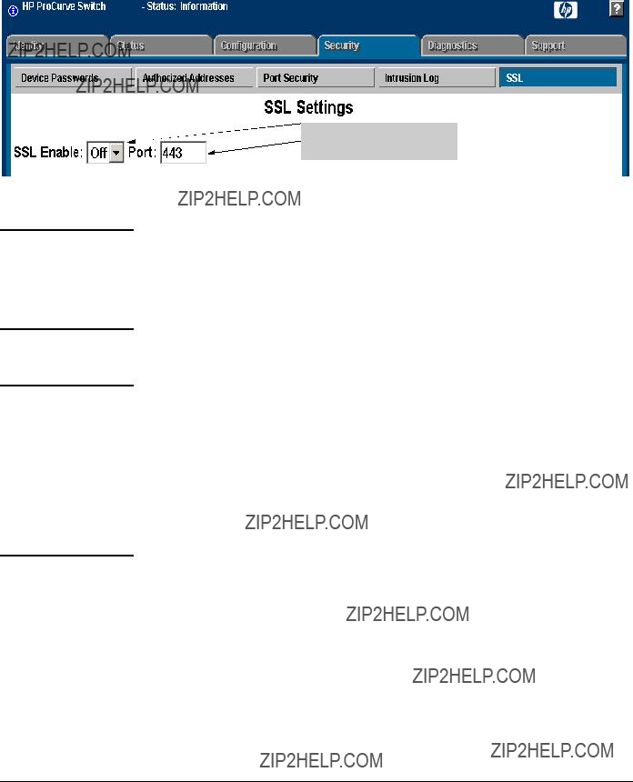
Configuring Secure Socket Layer (SSL)
Configuring the Switch for SSL Operation
Enable SLL
and port number Selection
Figure
Note on Port Number
Caution
ProCurve recommends using the default IP port number (443). However, you can use
SSL does not protect the switch from unauthorized access via the Telnet, SNMP, or the serial port. While Telnet access can be restricted by the use of passwords local to the switch, if you are unsure of the security this provides, you may want to disable Telnet access (no telnet). If you need to increase SNMP security, use SNMP version 3 only for SNMP access. Another security measure is to use the Authorized IP Managers feature described in the switch???s Security Guide. To protect against unauthorized access to the serial port (and the Clear button, which removes local password protection), keep physical access to the switch restricted to authorized personnel.
Configuring Secure Socket Layer (SSL)
Common Errors in SSL Setup
Common Errors in SSL Setup

Configuring Secure Socket Layer (SSL)
Common Errors in SSL Setup
??? This page is intentionally unused. ???

8
Configuring
Contents
Overview . . . . . . . . . . . . . . . . . . . . . . . . . . . . . . . . . . . . . . . . . . . . . . . . . . . . . .
Why Use
General Features . . . . . . . . . . . . . . . . . . . . . . . . . . . . . . . . . . . . . . . . . . . .
How 802.1X Operates . . . . . . . . . . . . . . . . . . . . . . . . . . . . . . . . . . . . . . . . . . . .
Authenticator Operation . . . . . . . . . . . . . . . . . . . . . . . . . . . . . . . . . . . . .
Terminology . . . . . . . . . . . . . . . . . . . . . . . . . . . . . . . . . . . . . . . . . . . . . . . . . . .
General Operating Rules and Notes . . . . . . . . . . . . . . . . . . . . . . . . . . . . . . .
General Setup Procedure for
Configuring Switch Ports as 802.1X Authenticators . . . . . . . . . . . . . . . . .
Option For Authenticator Ports: Configure
Allow Only 802.1X Devices . . . . . . . . . . . . . . . . . . . . . . . . . . . . . . . . . . . . . .

Configuring
Contents
Configuring Switch Ports To Operate As Supplicants for
802.1X Connections to Other Switches . . . . . . . . . . . . . . . . . . . . . . . . . . . .
Displaying 802.1X Configuration, Statistics, and Counters . . . . . . . . . . . .
How RADIUS/802.1X Authentication Affects VLAN Operation . . . . . . . .
Messages Related to 802.1X Operation . . . . . . . . . . . . . . . . . . . . . . . . . . . .
Configuring
Overview
Overview
Configuring Switch Ports as 802.1X Authenticators Configuring 802.1X Open VLAN Mode
Configuring Switch Ports to Operate as 802.1X Supplicants Displaying 802.1X Configuration, Statistics, and Counters How 802.1X Affects VLAN Operation
RADIUS Authentication and Accounting
Refer to ???RADIUS Authentication and Accounting??? on page
Why Use
Local area networks are often deployed in a way that allows unauthorized clients to attach to network devices, or allows unauthorized users to get access to unattended clients on a network. Also, the use of DHCP services and zero configuration make access to networking services easily available. This exposes the network to unauthorized use and malicious attacks. While access to the network should be made easy, uncontrolled and unauthorized access is usually not desirable. 802.1X provides access control along with the ability to control user profiles from a central RADIUS server while allowing users access from multiple points within the network.
General Features
802.1X on the ProCurve switches covered in this manual includes the follow- ing:
???Switch operation as both an authenticator (for supplicants having a
???Authentication of 802.1X clients using a RADIUS server and either the EAP or CHAP protocol.
???Provision for enabling clients that do not have 802.1 supplicant soft- ware to use the switch as a path for downloading the software and initiating the authentication process (802.1X Open VLAN mode).
???Supplicant implementation using CHAP authentication and indepen- dent username and password configuration on each port.
???Prevention of traffic flow in either direction on unauthorized ports.

Configuring
Overview
???Local authentication of 802.1X clients using the switch???s local user- name and password (as an alternative to RADIUS authentication).
???Temporary
???Session accounting with a RADIUS server, including the accounting update interval.
???Use of Show commands to display session counters.
???With
Authenticating Users.
Providing a Path for Downloading 802.1X Supplicant Software. For clients that do not have the necessary 802.1X supplicant software, there is also the option to configure the 802.1X Open VLAN mode. This mode allows you to assign such clients to an isolated VLAN through which you can provide the necessary supplicant software these clients need to begin the authentication process. (Refer to ???802.1X Open VLAN Mode??? on page
Authenticating One Switch to Another. 802.1X authentication also enables the switch to operate as a supplicant when connected to a port on another switch running 802.1X authentication.

Configuring
Figure
Accounting . The switch also provides RADIUS Network accounting for 802.1X access. Refer to ???RADIUS Authentication and Accounting??? on page

Configuring
How 802.1X Operates
How 802.1X Operates
Authenticator Operation
This operation provides security on a direct,
1.When the switch detects the client on the port, it blocks access to the LAN from that port.
2.The switch responds with an identity request.
3.The client responds with a user name that uniquely defines this request for the client.
4.The switch responds in one of the following ways:
???If 802.1X
i.The server responds with an access challenge which the switch forwards to the client.
ii.The client then provides identifying credentials (such as a user certificate), which the switch forwards to the RADIUS server.
iii.The RADIUS server then checks the credentials provided by the client.
iv.If the client is successfully authenticated and authorized to con- nect to the network, then the server notifies the switch to allow access to the client. Otherwise, access is denied and the port remains blocked.
???If 802.1X
i.The switch compares the client???s credentials with the username and password configured in the switch (Operator or Manager level).
ii.If the client is successfully authenticated and authorized to con- nect to the network, then the switch allows access to the client. Otherwise, access is denied and the port remains blocked.

Configuring
How 802.1X Operates
This operation provides security on links between
???Switch ???A??? has port A1 configured for 802.1X supplicant operation.
???You want to connect port A1 on switch ???A??? to port B5 on switch ???B???.
Switch ???B???

 Port B5
Port A1
Switch ???A???
Port A1 Configured as an
802.1X Supplicant
Figure
1.When port A1 on switch ???A??? is first connected to a port on switch ???B???, or if the ports are already connected and either switch reboots, port A1 begins sending start packets to port B5 on switch ???B???.
???If, after the supplicant port sends the configured number of start packets, it does not receive a response, it assumes that switch ???B??? is not
???If, after sending one or more start packets, port A1 receives a request packet from port B5, then switch ???B??? is operating as an 802.1X authenticator. The supplicant port then sends a response/ID packet. Switch ???B??? forwards this request to a RADIUS server.
2.The RADIUS server then responds with an MD5 access challenge that switch ???B??? forwards to port A1 on switch ???A???.
3.Port A1 replies with an MD5 hash response based on its username and password or other unique credentials. Switch ???B??? forwards this response to the RADIUS server.
4.The RADIUS server then analyzes the response and sends either a ???suc- cess??? or ???failure??? packet back through switch ???B??? to port A1.
???A ???success??? response unblocks port B5 to normal traffic from port A1.

Configuring
Terminology
???A ???failure??? response continues the block on port B5 and causes port A1 to wait for the
Terminology
Authentication Server: The entity providing an authentication service to the switch when the switch is configured to operate as an authenticator. In the case of an ProCurve switch running 802.1X, this is a RADIUS server (unless local authentication is used, in which case the switch performs this function using its own username and password for authenticating a supplicant).
Authenticator: In ProCurve switch applications, a device such as a switch that requires a supplicant to provide the proper credentials (username and password) before being allowed access to the network.
CHAP (MD5): Challenge Handshake Authentication Protocol.
Client: In this application, an
Configuring
Terminology
EAP (Extensible Authentication Protocol): EAP enables network access that supports multiple authentication methods.
EAPOL: Extensible Authentication Protocol Over LAN, as defined in the
802.1X standard.
Friendly Client: A client that does not pose a security risk if given access to the switch and your network.
MD5: An algorithm for calculating a unique digital signature over a stream of bytes. It is used by CHAP to perform authentication without revealing the shared secret (password).
PVID (Port VID): This is the VLAN ID for the untagged VLAN to which an 802.1X port belongs.
Static VLAN: A VLAN that has been configured as ???permanent??? on the switch by using the CLI vlan < vid > command or the Menu interface.
Supplicant: The entity that must provide the proper credentials to the switch before receiving access to the network. This is usually an
Tagged VLAN Membership: This type of VLAN membership allows a port to be a member of multiple VLANs simultaneously. If a client connected to the port has an operating system that supports 802.1q VLAN tagging, then the client can access VLANs for which the port is a tagged member. If the client does not support VLAN tagging, then it can access only a VLAN for which the port is an untagged member. (A port can be an untagged member of only one VLAN at a time.) 802.1X Open VLAN mode does not affect a port???s tagged VLAN access unless the port is statically configured as a member of a VLAN that is also configured as the

Configuring
General Operating Rules and Notes
member of that VLAN as long as at least one other port on the switch is statically configured as a tagged or untagged member of the same Unau-
Untagged VLAN Membership: A port can be an untagged member of only one VLAN. (In the
General Operating Rules and Notes
???When a port on the switch is configured as either an authenticator or supplicant and is connected to another device, rebooting the switch causes a
???When a port on the switch is configured as an authenticator, it will block access to a client that either does not provide the proper authentication credentials or is not
???If a port on switch ???A??? is configured as an 802.1X supplicant and is connected to a port on another switch, ???B???, that is not
???
???
You can configure a port as both an 802.1X authenticator and an 802.1X supplicant.
If a port on switch ???A??? is configured as both an 802.1X authenticator and supplicant and is connected to a port on another switch, ???B???, that is not
Configuring
General Operating Rules and Notes
???If a client already has access to a switch port when you configure the port for 802.1X authenticator operation, the port will block the client from further network access until it can be authenticated.
???On a port configured for 802.1X with RADIUS authentication, if the RADIUS server specifies a VLAN for the supplicant and the port is a trunk member, the port will be blocked. If the port is later removed from the trunk, the port will try to authenticate the supplicant. If authentication is successful, the port becomes unblocked. Similarly, if the supplicant is authenticated and later the port becomes a trunk member, the port will be blocked. If the port is then removed from the trunk, it tries to
???To help maintain security, 802.1X and LACP cannot both be enabled on the same port. If you try to configure 802.1X on a port already configured for LACP (or the reverse) you will see a message similar to the following:
Error configuring port X: LACP and 802.1X cannot be run together.
Note on 802.1X To help maintain security, the switch does not allow 802.1X and LACP to both and LACP be enabled at the same time on the same port. Refer to ???802.1X Operating
Messages??? on page

Configuring
General Setup Procedure for
General Setup Procedure for
Access Control (802.1X)
Do These Steps Before You Configure 802.1X Operation
1.Configure a local username and password on the switch for both the Operator (login) and Manager (enable) access levels. (While this may or may not be required for your 802.1X configuration, ProCurve recommends that you use a local username and password pair at least until your other security measures are in place.)
2.Determine which ports on the switch you want to operate as authentica- tors and/or supplicants, and disable LACP on these ports. (See the ???Note on 802.1X and LACP??? on page
3.Determine whether to use the optional 802.1X Open VLAN mode for clients that are not
4.For each port you want to operate as a supplicant, determine a username and password pair. You can either use the same pair for each port or use unique pairs for individual ports or subgroups of ports. (This can also be the same local username/password pair that you assign to the switch.)
5.Unless you are using only the switch???s local username and password for 802.1X authentication, configure at least one RADIUS server to authenti- cate access requests coming through the ports on the switch from external supplicants (including switch ports operating as 802.1X supplicants). You can use up to three RADIUS servers for authentication; one primary and two backups. Refer to the documentation provided with your RADIUS application.

Configuring
General Setup Procedure for
Overview: Configuring 802.1X Authentication on the
Switch
This section outlines the steps for configuring 802.1X on the switch. For detailed information on each step, refer to ???RADIUS Authentication and Accounting??? on page
1.Enable 802.1X authentication on the individual ports you want to serve as authenticators. On the ports you will use as authenticators, either accept the default 802.1X settings or change them, as necessary. Note that, by default, the
2.If you want to provide a path for clients without 802.1X supplicant software to download the software so that they can initiate an authenti- cation session, enable the 802.1X Open VLAN mode on the ports you want to support this feature. Refer to page
3.Configure the 802.1X authentication type. Options include:
???Local Operator username and password (the default). This option allows a client to use the switch???s local username and password as valid 802.1X credentials for network access.
???EAP RADIUS: This option requires your RADIUS server application to support EAP authentication for 802.1X.
???CHAP (MD5) RADIUS: This option requires your RADIUS server application to support CHAP (MD5) authentication.
See page
4.If you select either
5.Enable 802.1X authentication on the switch. See page
6.Test both the authorized and unauthorized access to your system to ensure that the 802.1X authentication works properly on the ports you have configured for

Configuring
General Setup Procedure for
7.If you are using Port Security on the switch, configure the switch to allow only 802.1X access on ports configured for 802.1X operation, and (if desired) the action to take if an unauthorized device attempts access through an 802.1X port. See page
8.If you want a port on the switch to operate as a supplicant in a connection with a port operating as an 802.1X authenticator on another device, then configure the supplicant operation. (Refer to ???Configuring Switch Ports To Operate As Supplicants for 802.1X Connections to Other Switches??? on page

Note
Configuring
Configuring Switch Ports as 802.1X Authenticators
Configuring Switch Ports as 802.1X
Authenticators
1. Enable 802.1X Authentication on Selected Ports
This task configures the individual ports you want to operate as 802.1X authenticators for
When you enable 802.1X authentication on a port, the switch automatically disables LACP on that port. However, if the port is already operating in an LACP trunk, you must remove the port from the trunk before you can config- ure it for 802.1X authentication.

Configuring
Configuring Switch Ports as 802.1X Authenticators
Syntax: aaa
Enables specified ports to operate as 802.1X authenti- cators with current per- port authenticator configura- tion. To activate configured 802.1X operation, you must enable 802.1X authentication. Refer to ???5. Enable 802.1X Authentication on the switch??? on page
[control < authorized | auto | unauthorized >]
Controls authentication mode on the specified port:
authorized: Also termed Force Authorized. Grants access to any device connected to the port. In this case, the device does not have to provide 802.1X credentials or support 802.1X authentication. (However, you can still configure console, Telnet, or SSH security on the port.)
auto (the default): The device connected to the port must support 802.1X authentication and provide valid credentials in order to get network access. (You have the option of using the Open VLAN mode to provide a path for clients without 802.1X supplicant software to download this software and begin the authentication process. Refer to ???802.1X Open VLAN Mode??? on page
unauthorized: Also termed Force Unauthorized. Do not grant access to the network, regardless of whether the device provides the correct credentials and has 802.1X support. In this state, the port blocks access to any connected device.
Sets the period during which the port does not try to acquire a supplicant. The period begins after the last attempt authorized by the
Sets the period the port waits to retransmit the next EAPOL PDU during an authentication session. (Default: 30 seconds)

Configuring
Configuring Switch Ports as 802.1X Authenticators
Sets the period of time the switch waits for a supplicant response to an EAP re quest. If the supplicant does not respond within the configured time frame, the session times out. (Default: 30 seconds)
aaa
Sets the period of time the switch waits for a server response to an authentication request. If there is no response within the configured time frame, the switch assumes that the authentication attempt has timed out. Depending on the current
Sets the number of authentication attempts that must
Sets the period of time after which clients connected must be
Configures an existing static VLAN to be the Unauthor-
Configuring
Configuring Switch Ports as 802.1X Authenticators
Configures an existing, static VLAN to be the Autho-
aaa
[initialize]
On the specified ports, blocks inbound and outbound traffic and restarts the 802.1X authentication process. This happens only on ports configured with control auto and actively operating as 802.1X authenticators.
Note: If a specified port is configured with control authorized and
[reauthenticate]
Forces reauthentication (unless the authenticator is in 'HELD' state).
Clears authenticator statistics counters.
Configuring
Configuring Switch Ports as 802.1X Authenticators
3. Configure the 802.1X Authentication Method
This task specifies how the switch will authenticate the credentials provided by a supplicant connected to a switch port configured as an 802.1X authenti- cator.
Syntax: aaa authentication
Determines the type of RADIUS authentication to use.
local Use the switch???s local username and password for supplicant authentication.
For example, to enable the switch to perform 802.1X authentication using one or more
Configuration command for
802.1X
Figure

Configuring
Configuring Switch Ports as 802.1X Authenticators
4. Enter the RADIUS Host IP Address(es)
If you selected either
Syntax: radius host <
Adds a server to the RADIUS configuration.
[key <
Optional. Specifies an encryption key for use during authentication (or accounting) sessions with the spec- ified server. This key must match the key used on the RADIUS server. Use this option only if the specified server requires a different key than configured for the global encryption key.
Specifies the global encryption key the switch uses for sessions with servers for which the switch does not have a
5. Enable 802.1X Authentication on the Switch
After configuring 802.1X authentication as described in the preceding four sections, activate it with this command:
Syntax: aaa
Activates 802.1X

Configuring
802.1X Open VLAN Mode
802.1X Open VLAN Mode
This section describes how to use the 802.1X Open VLAN mode to configure
Introduction
Configuring the 802.1X Open VLAN mode on a port changes how the port responds when it detects a new client. In earlier releases, a ???friendly??? client computer not running 802.1X supplicant software could not be authenticated on a port protected by 802.1X access security. As a result, the port would become blocked and the client could not access the network. This prevented the client from:
???Acquiring IP addressing from a DHCP server
???Downloading the 802.1X supplicant software necessary for an authen- tication session
The 802.1X Open VLAN mode solves this problem by temporarily suspending the port???s static, tagged and untagged VLAN memberships and placing the port in a designated

Configuring
802.1X Open VLAN Mode
1.1st Priority: The port joins a VLAN to which it has been assigned by a RADIUS server during authentication.
2.2nd Priority: If RADIUS authentication does not include assigning the port to a VLAN, then the switch assigns the port to the VLAN entered in the port???s 802.1X configuration as an
3.3rd Priority: If the port does not have an
If the port is not configured for any of the above, then it must be a tagged member of at least one static VLAN. If the client is capable of operating with that tagged VLAN, then it receives access to the VLAN. Otherwise, the con- nection fails.
Use Models for 802.1X Open VLAN Modes
You can apply the 802.1X Open VLAN mode in more than one way. Depending on your use, you will need to create one or two static VLANs on the switch for exclusive use by
???
???

Open VLAN mode with both of the following configured:

Configuring
802.1X Open VLAN Mode
Open VLAN Mode with Only an
???When the port detects a client, it automatically becomes an untagged member of this VLAN. To limit security risks, the network services and access available on this VLAN should include only what a client needs to enable an authentication session. If the port is statically configured as an untagged member of another VLAN, the switch temporarily removes the port from membership in this other VLAN while membership in the
???After the client is authenticated, and if the port is statically configured as an untagged member of another VLAN, the port???s access to this other VLAN is restored.
Note: If RADIUS authentication assigns a VLAN to the port, this assignment overrides any statically configured, untagged VLAN membership on the port (while the client is connected).
???If the port is statically configured as a tagged member of a VLAN that is not used by 802.1X Open VLAN mode, the port returns to tagged membership in this VLAN upon successful client authentication. This happens even if the RADIUS server assigns the port to another, authorized VLAN. Note that if the port is already configured as a tagged member of a VLAN that RADIUS assigns as an authorized VLAN, then the port becomes an untagged member of that VLAN for the duration of the client connection. After the client disconnects, the port returns to tagged membership in that VLAN.
Open VLAN Mode with Only an
???Port automatically blocks a client that cannot initiate an authentication session.
???If the client successfully completes an authentication session, the port becomes an untagged member of this VLAN.
Note: if RADIUS authentication assigns a VLAN, the port temporarily becomes an untagged member of the RADIUS- assigned VLAN
???If the port is statically configured as a tagged member of any other VLAN, the port returns to tagged membership in this VLAN upon successful client authentication. This happens even if the RADIUS server assigns the port to another, authorized VLAN. If the port is already configured as a tagged member of a VLAN that RADIUS assigns as an authorized VLAN, then the port becomes an untagged member of that VLAN for the duration of the client connection. After the client disconnects, the port returns to tagged membership in that VLAN.

Configuring
802.1X Open VLAN Mode
Operating Rules for
Static VLANs used as Authorized- These must be configured on the switch before you configure an Client or
command or the VLAN Menu screen in the Menu interface.)
VLAN Assignment Received from a RADIUS Server
If the RADIUS server specifies a VLAN for an authenticated supplicant connected to an 802.1X authenticator port, this VLAN assignment overrides any
Temporary VLAN Membership During
a Client Session
Effect of
???Port membership in a VLAN assigned to operate as the
???Port membership in a VLAN assigned to operate as the Authorized- Client VLAN is also temporary, and ends when the client disconnects from the port.If a VLAN assignment from a RADIUS server is used instead, the same rule applies.
???When an unauthenticated client connects to a port that is already configured with a static, untagged VLAN, the switch temporarily moves the port to the
???When the client either becomes authenticated or disconnects, the port leaves the

Configuring
802.1X Open VLAN Mode
Effect of
???When a client becomes authenticated on a port that is already configured with a static, untagged VLAN, the switch temporarily moves the port to the
???When the authenticated client disconnects, the switch removes the port from the
Effect of Failed Client Authentication
Attempt
When there is an
each other. However, in this case, you can improve security between authen- ticator ports by using the switch???s

Configuring
802.1X Open VLAN Mode
Setting Up and Configuring 802.1X Open VLAN Mode
Preparation. This section assumes use of both the
Before you configure the 802.1X Open VLAN mode on a port:
???Statically configure an
???Statically configure an
Note that if an 802.1X authenticator port is an untagged member of another VLAN, the port???s access to that other VLAN will be temporarily removed while an authenticated client is connected to the port. For example, if:
i.Port A5 is an untagged member of VLAN 1 (the default VLAN).
ii.You configure port A5 as an 802.1X authenticator port.
iii.You configure port A5 to use an
Then, if a client connects to port A5 and is authenticated, port A5 becomes an untagged member of the
???If you expect friendly clients to connect without having 802.1X suppli- cant software running, provide a server on the
???A client must either have a valid IP address configured before connecting to the switch, or download one through the Unauthorized- Client VLAN from a DHCP server. In the latter case, you will need to provide DHCP services on the
Configuring
802.1X Open VLAN Mode
??? Ensure that the switch is connected to a RADIUS server configured
Configuring General 802.1X Operation: These steps enable 802.1X authentication, and must be done before configuring 802.1X VLAN operation.
1.Enable 802.1X authentication on the individual ports you want to serve as authenticators. (The switch automatically disables LACP on the ports on which you enable 802.1X.) On the ports you will use as authenticators with VLAN operation, ensure that the (default)
Syntax: aaa
Activates 802.1X
2.Configure the 802.1X authentication type. Options include:
Syntax: aaa authentication
Determines the type of RADIUS authentication to use.
local: Use the switch???s local username and password for supplicant authentication (the default).
Configuring
802.1X Open VLAN Mode
3.If you selected either
Syntax: radius host <
Adds a server to the RADIUS configuration.
[key <
Optional. Specifies an encryption key for use with the specified server. This key must match the key used on the RADIUS server. Use this option only if the specified server requires a different key than configured for the global encryption key.
Specifies the global encryption key the switch uses for sessions with servers for which the switch does not have a
4.Activate authentication on the switch.
Syntax: aaa
Activates 802.1X
5.Test both the authorized and unauthorized access to your system to ensure that the 802.1X authentication works properly on the ports you have configured for

Configuring
802.1X Open VLAN Mode
Configuring 802.1X Open VLAN Mode. Use these commands to actually configure Open VLAN mode. For a listing of the steps needed to prepare the switch for using Open VLAN mode, refer to ???Preparation??? on page
Syntax: aaa
Configures an existing, static VLAN to be the Authorized-
Client VLAN.
[<
Configures an existing, static VLAN to be the Unauthor-
For example, suppose you want to configure 802.1X
???These two static VLANs already exist on the switch:
???Unauthorized, VID = 80
???Authorized, VID = 81
???Your RADIUS server has an IP address of 10.28.127.101. The server uses rad4all as a
???The switch's default VLAN is already configured with an IP address of 10.28.127.100 and a network mask of 255.255.255.0
ProCurve(config)# aaa authentication
Configures the switch for 802.1X authentication using an
ProCurve(config)# aaa
Configures ports A10 - A20 as 802.1 authenticator ports.
ProCurve(config)# radius host 10.28.127.101 key rad4all
Configures the switch to look for a RADIUS server with an IP address of 10.28.127.101 and an encryption key of rad4all.
ProCurve(config)# aaa
Configures ports A10 - A20 to use VLAN 80 as the
ProCurve(config)# aaa
Configures ports A10 - A20 to use VLAN 81 as the
ProCurve(config)# aaa
Activates 802.1X

Configuring
802.1X Open VLAN Mode
Inspecting 802.1X Open VLAN Mode Operation. For information and an example on viewing current Open VLAN mode operation, refer to ???Viewing 802.1X Open VLAN Mode Status??? on page
802.1X Open VLAN Operating Notes
???Although you can configure Open VLAN mode to use the same VLAN for both the
???While an
???A VLAN used as the
???If a port is configured as a tagged member of VLAN "X" that is not used as an
???When a client???s authentication attempt on an
???During an authentication session on a port in 802.1X Open VLAN mode, if RADIUS specifies membership in an untagged VLAN, this assignment overrides port membership in the

Configuring
Option For Authenticator Ports: Configure
???If an authenticated client loses authentication during a session in 802.1X Open VLAN mode, the port VLAN membership reverts back to the
Option For Authenticator Ports:
Configure
802.1X Devices
If you use
Syntax:

Configuring
Option For Authenticator Ports: Configure
Note on Blocking a Non- 802.1X Device
If the port???s 802.1X authenticator control mode is configured to authorized (as shown below, instead of auto), then the first source MAC address from any device, whether
aaa
With 802.1X authentication disabled on a port or set to authorized (Force Authorize), the port may learn a MAC address that you don???t want authorized. If this occurs, you can block access by the unauthorized,
???If 802.1X authentication is disabled on the port, use these command syntaxes to enable it and allow only an
aaa
Enables 802.1X authentication on the port.
aaa
Forces the port to accept only a device that supports 802.1X and supplies valid credentials.
???If 802.1X authentication is enabled on the port, but set to authorized (Force Authorized), use this command syntax to allow only an 802.1X- aware
device:
aaa
Forces the port to accept only a device that supports 802.1X and supplies valid credentials.
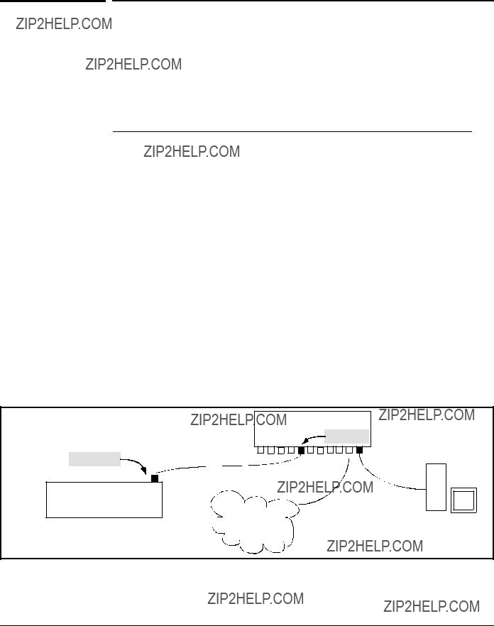
Configuring
Configuring Switch Ports To Operate As Supplicants for 802.1X Connections to Other Switches
Configuring Switch Ports To Operate As
Supplicants for 802.1X Connections to
Other Switches
You can configure a switch port to operate as a supplicant in a connection to a port on another
For example, suppose that you want to connect two switches, where:
???Switch ???A??? has port A1 configured for 802.1X supplicant operation
???You want to connect port A1 on switch ???A??? to port B5 on switch ???B???.
Port A1
Switch ???A???
Port A1 Configured as an
802.1X Supplicant
Figure

Configuring
Configuring Switch Ports To Operate As Supplicants for 802.1X Connections to Other Switches
1.When port A1 on switch ???A??? is first connected to a port on switch ???B???, or if the ports are already connected and either switch reboots, port A1 begins sending start packets to port B5 on switch ???B???.
???If, after the supplicant port sends the configured number of start request packets, it does not receive a response, it assumes that switch ???B??? is not
???If, after sending one or more start request packets, port A1 receives a request packet from port B5, then switch ???B??? is operating as an 802.1X authenticator. The supplicant port then sends a response/ID packet. If switch ???B??? is configured for RADIUS authentication, it forwards this request to a RADIUS server. If switch ???B??? is configured for Local 802.1X authentication (page
2.The RADIUS server then responds with an access challenge that switch ???B??? forwards to port A1 on switch ???A???.
3.Port A1 replies with a hash response based on its unique credentials. Switch ???B??? forwards this response to the RADIUS server.
4.The RADIUS server then analyzes the response and sends either a ???suc- cess??? or ???failure??? packet back through switch ???B??? to port A1.
???A ???success??? response unblocks port B5 to normal traffic from port A1.
???A ???failure??? response continues the block on port B5 and causes port A1 to wait for the

Configuring
Configuring Switch Ports To Operate As Supplicants for 802.1X Connections to Other Switches
Configuring a Supplicant Switch Port. Note that you must enable suppli- cant operation on a port before you can change the supplicant configuration. This means you must execute the supplicant command once without any other parameters, then execute it again with a supplicant parameter you want to configure. If the intended authenticator port uses RADIUS authentication, then use the identity and secret options to configure the
Syntax: aaa
To enable supplicant operation on the designated ports, execute this command without any other parameters. After doing this, you can use the command again with the following parameters to configure supplicant oper- tion. (Use one instance of the command for each parameter you want to configure The no form disables supplicant operation on the designated port(s).
[identity < username >]
Sets the username and password to pass to the authen- ticator port when a
[secret]
Enter secret: < password >
Repeat secret: < password >
Sets the secret password to be used by the port suppli- cant when an MD5 authentication request is received from an authenticator. The switch prompts you to enter the secret password after the command is invoked.

Configuring
Configuring Switch Ports To Operate As Supplicants for 802.1X Connections to Other Switches
aaa
Sets the period of time the port waits to receive a challenge from the authenticator. If the request times out, the port sends another authentication request, up to the number of attempts specified by the
Defines the maximum number of times the supplicant port requests authentication. See step 1 on page
Sets the time period the supplicant port waits after an active 802.1X session fails before trying to re- acquire the authenticator port. (Default: 60 seconds)
Sets the time period between Start packet retransmis- sions. That is, after a supplicant sends a start packet, it waits during the
aaa
On the specified ports, blocks inbound and outbound traffic and restarts the 802.1X authentication process. Affects only ports configured as 802.1X supplicants.
Clears and restarts the 802.1X supplicant statistics counters.

Configuring
Displaying 802.1X Configuration, Statistics, and Counters
Displaying 802.1X Configuration,
Statistics, and Counters
Show Commands for
Syntax: show
???Without [<
???With <
???With [<
???With [config | statistics |
For descriptions of [config | statistics |
Configuring
Displaying 802.1X Configuration, Statistics, and Counters
show
config [[e] <
Shows:
???Whether
???The 802.1X configuration of the ports configured as 802.1X authenticators
If you do not specify <
statistics [[e] <
Shows:
???Whether
???The statistics of the ports configured as 802.1X authenticators, including the supplicant???s MAC address, as determined by the content of the last EAPOL frame received on the port.
Does not display data for a specified port that is not enabled as an authenticator.
Shows:
???Whether
???The session status on the specified ports configured as 802.1X authenticators
Also, for each port, the ???User??? column lists the user name the supplicant included in its response packet. (For the switch, this is the identity setting included in the supplicant

Configuring
Displaying 802.1X Configuration, Statistics, and Counters
Viewing 802.1X Open VLAN Mode Status
You can examine the switch???s current VLAN status by using the show port- access authenticator and show vlan <
An Unauth VLAN ID appearing in the Current VLAN ID column for the same port indicates an unauthenticated client is connected to this port.
(Assumes that the port is not a statically configured member of VLAN 100.)
Items 1 through 3 indicate that an authenticated client is connected to port B2:
1.Open in the Status column
2.Authorized in the Authenticator State column
3.The Auth VLAN ID (101) is also in the Current VLAN ID column. (This assumes that the port is not a statically configured member of VLAN 101.)
4.A ???0??? in the row for port B3 indicates there is no Authorized VLAN configured for port B3.
5.???No PVID??? means there is currently no untagged VLAN membership on port B4.
Figure
Thus, in the show
???When the Auth VLAN ID is configured and matches the Current VLAN ID in the above command output, an authenticated client is connected to the port. (This assumes the port is not a statically configured member of the VLAN you are using for Auth VLAN.)

Configuring
Displaying 802.1X Configuration, Statistics, and Counters
???When the Unauth VLAN ID is configured and matches the Current VLAN ID in the above command output, an unauthenticated client is connected to the port. (This assumes the port is not a statically configured member of the VLAN you are using for Unauth VLAN.)
Note that because a temporary Open VLAN port assignment to either an authorized or unauthorized VLAN is an untagged VLAN membership, these assignments temporarily replace any other untagged VLAN membership that is statically configured on the port. For example, if port A12 is statically configured as an untagged member of VLAN 1, but is configured to use VLAN 25 as an authorized VLAN, then the port???s membership in VLAN 1 will be temporarily suspended whenever an authenticated 802.1X client is attached to the port.
Table
Access Control
This state is controlled by the following
ProCurve(config)# aaa
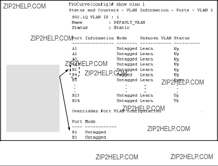
Configuring
Displaying 802.1X Configuration, Statistics, and Counters
Syntax: show vlan <
Displays the port status for the selected VLAN, including an indication of which port memberships have been temporarily overridden by Open VLAN mode.
Note that ports B1 and B3 are not in the upper listing, but are included under ???Overridden  Port VLAN configuration???. This shows that static, untagged VLAN memberships on ports B1 and B3 have been overridden by temporary assignment to the authorized or unauthorized VLAN. Using the show port- access authenticator < port- list > command shown in figure
Figure

Configuring
Displaying 802.1X Configuration, Statistics, and Counters
Show Commands for
Syntax: show
Shows the
Authenticated - Authentication completed (regardless of whether the attempt was successful).
Acquired - The port received a request for identification from an authenticator.
Authenticating - Authentication is in progress. Held - Authenticator sent notice of failure. The
supplicant port is waiting for the authenticator???s
For descriptions of the supplicant parameters, refer to ???Configuring a Supplicant Switch Port??? on page
show
Shows the
Note on Supplicant Statistics. For each port configured as a supplicant, show
???The supplicant port detects a different authenticator device.
???You use the aaa
???The switch reboots.
Thus, if the supplicant???s link to the authenticator fails, the supplicant retains the transaction statistics it most recently received until one of the above events occurs. Also, if you move a link with an authenticator from one

Configuring
How RADIUS/802.1X Authentication Affects VLAN Operation
supplicant port to another without clearing the statistics data from the first port, the authenticator???s MAC address will appear in the supplicant statistics for both ports.
How RADIUS/802.1X Authentication
Affects VLAN Operation
Static VLAN Requirement. RADIUS authentication for an 802.1X client on a given port can include a (static) VLAN requirement. (Refer to the documen- tation provided with your RADIUS application.) The static VLAN to which a RADIUS server assigns a client must already exist on the switch. If it does not exist or is a dynamic VLAN (created by GVRP), authentication fails. Also, for the session to proceed, the port must be an untagged member of the required VLAN. If it is not, the switch temporarily reassigns the port as described below.
If the Port Used by the Client Is Not Configured as an Untagged
Member of the Required Static VLAN: When a client is authenticated on port ???N???, if port ???N??? is not already configured as an untagged member of the static VLAN specified by the RADIUS server, then the switch temporarily assigns port ???N??? as an untagged member of the required VLAN (for the duration of the 802.1X session). At the same time, if port ???N??? is already configured as an untagged member of another VLAN, port ???N??? loses access to that other VLAN for the duration of the session. (This is because a port can be an untagged member of only one VLAN at a time.)

Configuring
How RADIUS/802.1X Authentication Affects VLAN Operation
For example, suppose that a
Scenario: An authorized 802.1X client requires access to VLAN 22 from port A2. However, access to VLAN 22 is blocked (not untagged or tagged) on port A2 and
Figure
In figure
???VLAN 22 becomes available as Untagged on port A2 for the duration of the session.
???VLAN 33 becomes unavailable to port A2 for the duration of the session (because there can be only one untagged VLAN on any port).
You can use the show vlan <
???You can see the temporary VLAN assignment by using the show vlan <
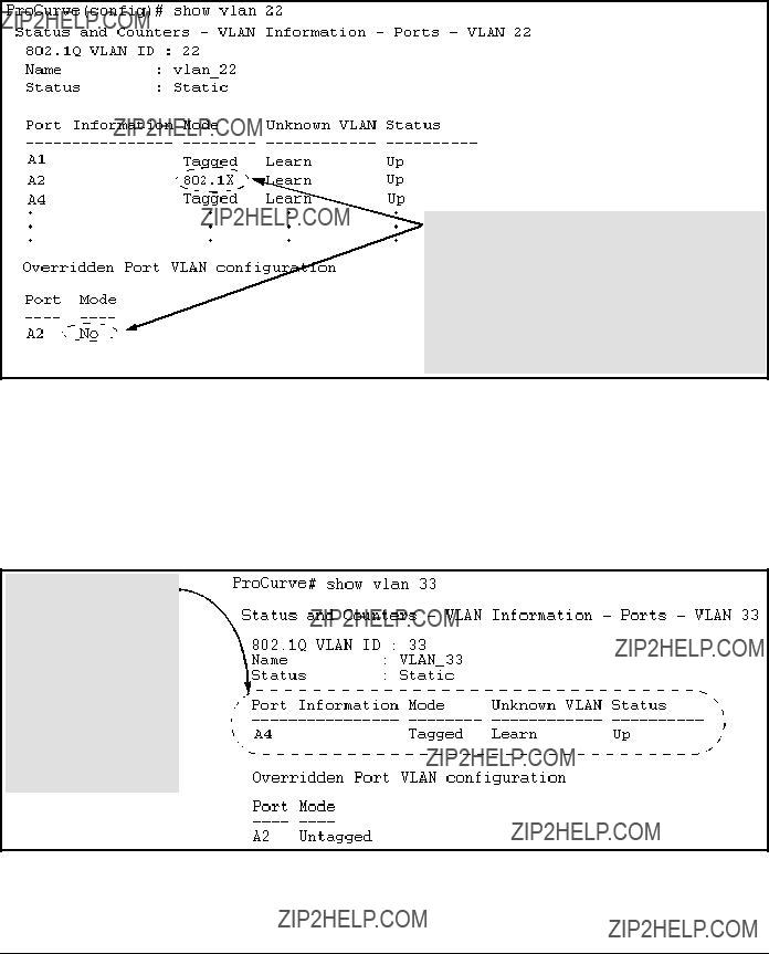
Configuring
How RADIUS/802.1X Authentication Affects VLAN Operation
This entry shows that port A2 is temporarily untagged on VLAN 22 for an 802.1X session. This is to accommodate an 802.1X client???s access, authenticated by a RADIUS server, where the server included an instruction to put the client???s access on VLAN 22.
Note: With the current VLAN configuration (figure
Otherwise, port A2 is not listed.
Figure
???With the preceding in mind, since (static) VLAN 33 is configured as untagged on port A2 (see figure
Even though port A2 is configured as Untagged on (static) VLAN 33 (see figure
Figure

Configuring
How RADIUS/802.1X Authentication Affects VLAN Operation
When the 802.1X client???s session on port A2 ends, the port discards the temporary untagged VLAN membership. At this time the static VLAN actually configured as untagged on the port again becomes available. Thus, when the
After the 802.1X session on VLAN 22 ends, the active configuration again includes VLAN 33 on port A2.
Figure

Configuring
Messages Related to 802.1X Operation
Messages Related to 802.1X Operation
Table
Port <
The ports in the port list have not been enabled as 802.1X authenticators. Use this command to enable the ports as authenticators:
LACP has been disabled on 802.1X port(s).
To maintain security, LACP is not allowed on ports configured for 802.1X authenticator operation. If you configure port security on a port on which LACP (active or passive) is configured, the switch removes the LACP configuration, displays a notice that LACP is disabled on the port(s), and enables 802.1X on that port.
Error configuring port <
Also, the switch will not allow you to configure LACP on a port on which port access (802.1X) is enabled.
9
Configuring and Monitoring Port Security
Contents
Contents . . . . . . . . . . . . . . . . . . . . . . . . . . . . . . . . . . . . . . . . . . . . . . . . . . . . . . .
Overview . . . . . . . . . . . . . . . . . . . . . . . . . . . . . . . . . . . . . . . . . . . . . . . . . . . . . .
Basic Operation . . . . . . . . . . . . . . . . . . . . . . . . . . . . . . . . . . . . . . . . . . . . .
Blocking Unauthorized Traffic . . . . . . . . . . . . . . . . . . . . . . . . . . . . . . . .
Trunk Group Exclusion . . . . . . . . . . . . . . . . . . . . . . . . . . . . . . . . . . . . . .
Planning Port Security . . . . . . . . . . . . . . . . . . . . . . . . . . . . . . . . . . . . . . . . . . .
Port Security Command Options and Operation . . . . . . . . . . . . . . . . . . . . .
MAC Lockdown . . . . . . . . . . . . . . . . . . . . . . . . . . . . . . . . . . . . . . . . . . . . . . .
Differences Between MAC Lockdown and Port Security . . . . . . . . .
Deploying MAC Lockdown . . . . . . . . . . . . . . . . . . . . . . . . . . . . . . . . . .
MAC Lockout . . . . . . . . . . . . . . . . . . . . . . . . . . . . . . . . . . . . . . . . . . . . . . . . .
Port Security and MAC Lockout . . . . . . . . . . . . . . . . . . . . . . . . . . . . . .
IP Lockdown . . . . . . . . . . . . . . . . . . . . . . . . . . . . . . . . . . . . . . . . . . . . . . . . . .
Web: Displaying and Configuring Port Security Features . . . . . . . . . . . . .
Reading Intrusion Alerts and Resetting Alert Flags . . . . . . . . . . . . . . . . . .
Web: Checking for Intrusions, Listing Intrusion Alerts, and
Resetting Alert Flags . . . . . . . . . . . . . . . . . . . . . . . . . . . . . . . . . . . . . . . .
Operating Notes for Port Security . . . . . . . . . . . . . . . . . . . . . . . . . . . . . . . .

Configuring and Monitoring Port Security
Overview
Overview
Using Port Security, you can configure each switch port with a unique list of the MAC addresses of devices that are authorized to access the network through that port. This enables individual ports to detect, prevent, and log attempts by unauthorized devices to communicate through the switch.
Basic Operation
Default Port Security Operation. The default port security setting for each port is off, or continuous. That is, any device can access a port without causing a security reaction.
Intruder Protection. A port that detects an ???intruder??? blocks the intruding device from transmitting to the network through that port.

Configuring and Monitoring Port Security
Overview
General Operation for Port Security. On a
???Alert flags that are captured by network management tools
???Alert Log entries in the switch???s web browser interface
???Event Log entries in the console interface
???Intrusion Log entries in either the menu interface, CLI, or web browser interface
For any port, you can configure the following:
???Authorized (MAC) Addresses: Specify up to eight devices (MAC addresses) that are allowed to send inbound traffic through the port. This feature:
???Closes the port to inbound traffic from any unauthorized devices that are connected to the port.
???Provides the option for sending an SNMP trap notifying of an attempted security violation to a network management station and, optionally, disables the port. (For more on configuring the switch for SNMP management, refer to ???Trap Receivers and Authentication Traps??? in the Management and Configuration Guide for your switch.)
Blocking Unauthorized Traffic
Unless you configure the switch to disable a port on which a security violation is detected, the switch security measures block unauthorized traffic without disabling the port. This implementation enables you to apply the security configuration to ports on which hubs, switches, or other devices are connected, and to maintain security while also maintaining network access to authorized users. For example:

Configuring and Monitoring Port Security
Overview
???PC1 can access Switch A.
???PCs 2 and 3 can access Switch B and Switch C, but are blocked from accessing switch A by the port security settings in switch A.
???Switch C is not authorized to access Switch A.
Figure
Trunk Group Exclusion
Port security does not operate on either a static or dynamic trunk group. If you configure port security on one or more ports that are later added to a trunk group, the switch will reset the port security parameters for those ports to the

Configuring and Monitoring Port Security
Planning Port Security
Planning Port Security
1.Plan your port security configuration and monitoring according to the following:
a.On which ports do you want port security?
b.Which devices (MAC addresses) are authorized on each port and how many devices do you want to allow per port (up to 8)?
c.Within the
d.For each port, what security actions do you want? (The switch automatically blocks intruders detected on that port from transmit- ting to the network.) You can configure the switch to (1) send intrusion alarms to an SNMP management station and to (2) option- ally disable the port on which the intrusion was detected.
e.How do you want to learn of the security violation attempts the switch detects? You can use one or more of these methods:
???Through network management (That is, do you want an SNMP trap sent to a net management station when a port detects a security violation attempt?)
???Through the switch???s Intrusion Log, available through the CLI, menu, and web browser interface
???Through the Event Log (in the menu interface or through the CLI show log command)
2.Use the CLI or web browser interface to configure port security operating and address controls. The following table describes the parameters.

Configuring and Monitoring Port Security
Port Security Command Options and Operation
Port Security Command Options and
Operation
Port Security Commands Used in This Section

Configuring and Monitoring Port Security
Port Security Command Options and Operation
Syntax:
Continuous (Default): Appears in the
Static: The
???You authorize MAC address
???You allow three devices on port A4, but the port detects these MAC addresses:
Port A4 then has the following list of authorized addresses:
The remaining MAC address,
Caution: When you use

Configuring and Monitoring Port Security
Port Security Command Options and Operation
Syntax:
(- Continued
Configured: The
Note: As of September, 2003, this option is available in the ProCurve Switch 2600 Series and the Switch 6108 running software release H.07.30 (or greater), and the ProCurve Switch 2800 Series. For availability in other switch products, refer to the latest release notes for such products on the ProCurve Networking website. (Refer to ???Getting Documentation From the Web??? on page
Based Access Control (802.1X)??? on page
When Learn Mode is set to static
Available for static
???If you use
???If you use

Configuring and Monitoring Port Security
Port Security Command Options and Operation
Syntax:
action < none |
Specifies whether an SNMP trap is sent to a network man- agement station. Operates when:
???Learn mode is set to
???Learn mode is set to
none (the default): Prevents an SNMP trap from being sent.
send alarm: Causes the switch to send an SNMP trap to a network management station.
For information on configuring the switch for SNMP management, refer to the Management and Configuration Guide for your switch.
Clears the intrusion flag for a specific port. (Refer to
???Reading Intrusion Alerts and Resetting Alert Flags??? on page

Configuring and Monitoring Port Security
Port Security Command Options and Operation
Retention of Static MAC Addresses
Learned MAC Addresses
In the following two cases, a port in Static learn mode
???The port learns a MAC address after you configure the port with learn- mode static in both the
???The port learns a MAC address after you configure the port with learn- mode static in only the
Assigned/Authorized MAC Addresses
If you manually assign a MAC address (using
Removing Learned and Assigned Static MAC Addresses
To remove a static MAC address, do one of the following:
???Delete the address by using no
???Download a configuration file that does not include the unwanted MAC address assignment.
???Reset the switch to its
Displaying Current Port Security Settings
The CLI uses the same command to provide two types of port security listings:
???All ports on the switch with their Learn Mode and (alarm) Action
???Only the specified ports with their Learn Mode, Address Limit, (alarm) Action, and Authorized Addresses
Configuring and Monitoring Port Security
Port Security Command Options and Operation
Using the CLI To Display Port Security Settings.
Syntax: show
show
show
Without port parameters, show
Figure
With port numbers included in the command, show
Figure

Configuring and Monitoring Port Security
Port Security Command Options and Operation
The following command example shows the option for entering a range of ports, including a series of
ProCurve(config)# show
Configuring Port Security
Using the CLI, you can:
???Configure port security and edit security settings.
???Add or delete devices from the list of authorized addresses for one or more ports.
???Clear the Intrusion flag on specific ports
Syntax:
(For the configured option, above, refer to the Note on page
no
<
Specifying Authorized Devices and Intrusion Responses
ProCurve(config)#
The next example does the same as the preceding example, except that it specifies a MAC address of

Configuring and Monitoring Port Security
Port Security Command Options and Operation
ProCurve(config)#
This example configures port A5 to:
???Allow two MAC addresses,
???Send an alarm to a management station if an intruder is detected on the port.
ProCurve(config)#
If you manually configure authorized devices (MAC addresses) and/or an alarm action on a port, those settings remain unless you either manually change them or reset the switch to its
???Allow only a MAC address of
???Reserve the option for adding two more specified MAC addresses at a later time without having to change the
???Send an alarm to a management station if an intruder is detected on the port.
ProCurve(config)#
Adding a MAC Address to an Existing Port List
To simply add a device (MAC address) to a port???s existing Authorized Addresses list, enter the port number with the
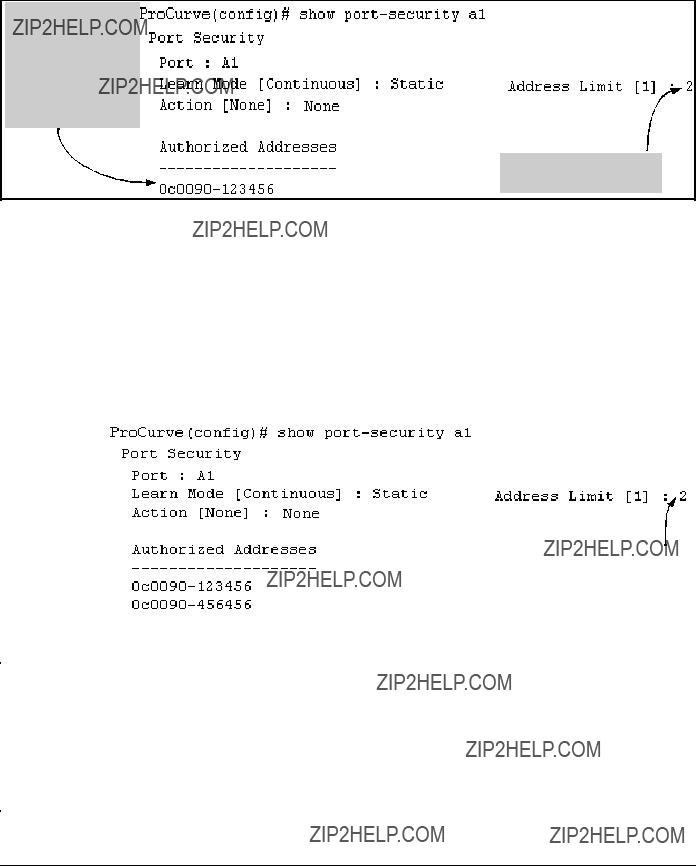
Configuring and Monitoring Port Security
Port Security Command Options and Operation
Although the Address Limit is set to 2, only one device has been authorized for this port. In this case you can add another without having to also increase the Address Limit.
The Address Limit has not been reached.
Figure
With the above configuration for port A1, the following command adds the
ProCurve(config)#
After executing the above command, the security configuration for port A1 appears as:


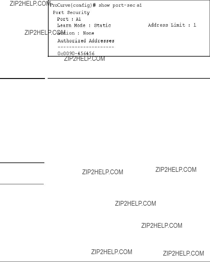


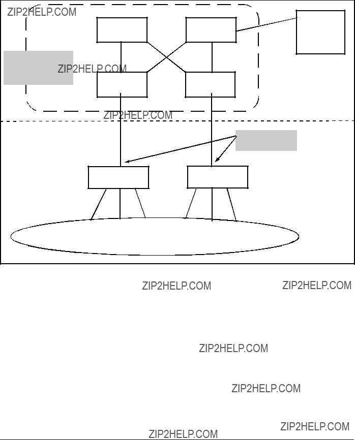

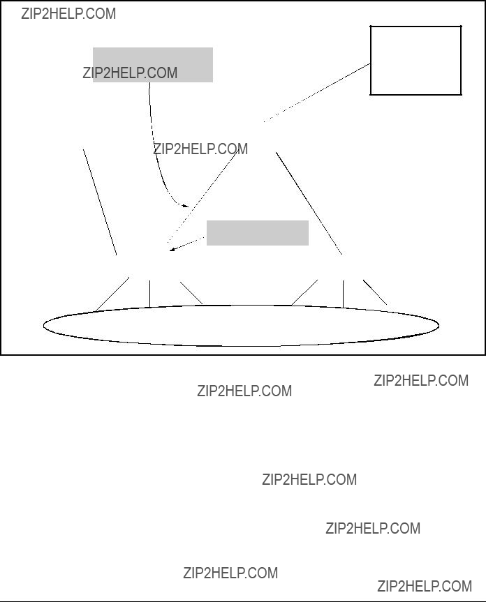


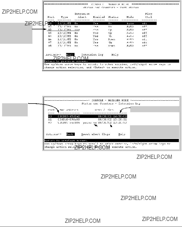


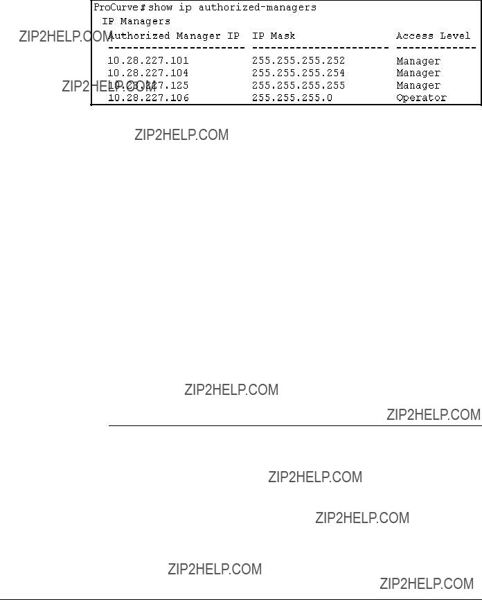


??? This page is intentionally unused. ???

?? 2000 - 2008
December 2008
Manual Part Number
 When removing
  reduce the Address Limit by 1 to prevent the port from automatically adding another device that it detects on the network.
 Indicates this intrusion on port A3 occurred prior to a reset (reboot) at the indicated time and date.
 Log Command with ???security??? for Search String
 2. Enter an Authorized Manager IP address here.
 management device, or edit the mask to allow
 4. Use the Space bar to select Manager or Operator access.