Quick Installation Guide
ProCurve Series
2510 Switch
www.procurve.com
Quick Installation Guide
ProCurve Series
2510 Switch
www.procurve.com

ProCurve Series 2510 Switch
Quick Installation Guide

?? Copyright 2006
Company, L.P.
The information contained herein is subject to change without notice. The only warranties for HP products and services are set forth in the express warranty statements accompanying such prod- ucts and services. Nothing herein should be construed as consti- tuting an additional warranty. HP shall not be liable for technical or editorial errors or omissions contained herein.
Publication Number
Safety
Before installing and operating these products, read the "Installa- tion Guidelines" beginning on page 4, and the safety statements in the "Safety and EMC Regulatory Statements".
Warranty
See the Customer Support/Warranty booklet included with the product.
A copy of the specific warranty terms applicable to your Hewlett- Packard product and replacement parts can be obtained from your HP sales and service office or
8000 Foothills Boulevard, m/s 5552 Roseville, California

Contents
Switch Ports . . . . . . . . . . . . . . . . . . . . . . . . . . . . . . . . . . . . . . . . . . . . . . . . . . 1
iii

European Community Declaration of Conformity . . . . . . . . . . . . . . . . . . . 29
Waste Electrical and Electronic Equipment (WEEE) Statements . . . . . . . . . . . 30
iv
Switch Overview
Switch Hardware Features
Switch Overview
Switch Hardware Features
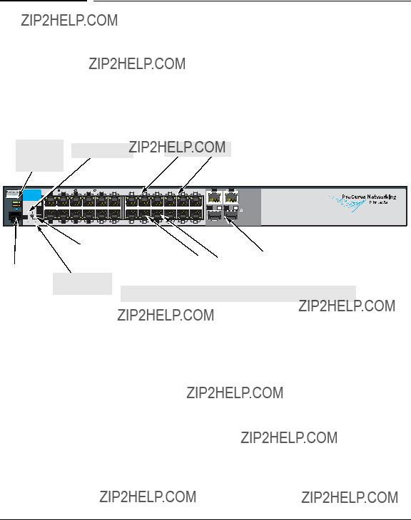
The ProCurve Series
Switch Ports
ProCurve Switch
Reset and Clear
buttons
*
The Switch
The
The Series 2510 Switch uses the console port to connect to a PC or workstation running a
The Series 2510 Switch does not have a power switch; it is powered on when connected to an active AC power source. This switch automatically adjusts to any voltage between
1

Switch Overview
Switch Hardware Features
2

Switch Overview
Switch Hardware Features
* The blinking behavior is an on/off cycle once every 1.6 seconds, approximately. ** The blinking behavior is an on/off cycle once every 0.8 seconds, approximately.
This button is used for these purposes:
???Deleting Passwords - When pressed by itself for at least one second, the button deletes any switch console access passwords that you may have configured. Use this feature if you have misplaced the password and need console access.
???Restoring Factory Default Configuration - When pressed with the Reset button in a specific pattern, any configuration changes you may have made through the switch console, the web browser interface, and SNMP management are removed, and the factory default configuration is restored to the switch. For the specific method to restore the factory default configuration, see the ???Troubleshooting??? chapter of the ???ProCurve Series 2510 Switch Installation and Getting Started Guide???, located on the ProCurve Networking Web site, www.procurve.com.
3

Switch Overview
Installing the Switch
Installing the Switch
Included Parts
The following components ship with a ProCurve Series 2510 switch:
???ProCurve Series 2510 Quick Installation Guide
???Console cable (Part number
???Customer Support/Warranty booklet
???Accessory kit
???two mounting brackets
???eight
???four
???four rubber feet
???Power cord, one of the following:
J a p a n P o w e r
C o r d W a r n i n g
Installation Procedure
1.Prepare the installation site (page
2.Verify the switch passes self test (page
4.Connect power to the switch (page
4
W A R N I N G
C a u t i o n s
Switch Overview
Installing the Switch
Installation Precautions
Follow these precautions when installing the Switch 2510.
???The rack or cabinet should be adequately secured to prevent it from becoming unstable and/or falling over.
Devices installed in a rack or cabinet should be mounted as low as possible, with the heaviest devices at the bottom and progressively lighter devices installed above.
???For safe operation, do not install the switch with the back face of the switch (with the air vents) facing either downward or upward.
???Left side vents cannot be placed downward. (That is, the left side of the unit while facing the front.)
???Ensure the power source circuits are properly grounded, then use the power cord supplied with the switch to connect it to the power source.
???If your installation requires a different power cord than the one supplied with the switch, be sure to use a power cord displaying the mark of the safety agency that defines the regulations for power cords in your country. The mark is your assurance that the power cord can be used safely with the switch.
???When installing the switch, the AC outlet should be near the switch and should be easily accessible in case the switch must be powered off.
???Ensure the switch does not overload the power circuits, wiring, and over- current protection. To determine the possibility of overloading the supply circuits, add together the ampere ratings of all devices installed on the same circuit as the switch and compare the total with the rating limit for the circuit. The maximum ampere ratings are usually printed on the devices near the AC power connectors.
???Do not install the switch in an environment where the operating ambient temperature might exceed 45??C (113??F).
???Ensure the air flow around the sides and back of the switch is not restricted.
???Use only supported genuine ProCurve
5

Switch Overview
Installing the Switch
1. Prepare the Installation Site
The cabling infrastructure must meet the requirements for the Switch 2510 ports. See the ProCurve Series 2510 Installation Guide on the ProCurve Web site for more information, www.procurve.com.
Installation Space Requirements
6

Switch Overview
Installing the Switch
1.Connect the power cord supplied with the switch to the power connector on the back of the switch, and then into a properly grounded electrical outlet
Connect power cord to the power connector
2.) Check the LEDs on the switch as described below.
When the switch is powered on, it performs its diagnostic self test. Self test takes approximately 50 seconds to complete.
Self Test LED Behavior:
During the self test:
???Initially, all the status, LED Mode and port LEDs are on for most of the duration of the test.
???Most of the LEDs go off and then may come on again during phases of the self test. For the duration of the self test, the Test LED stays on.
When the self test completes successfully:
???The Power and Fan Status LEDs remain on.
???The Fault and Test LEDs go off.
???The port LEDs on the front of the switch go into their normal opera- tional mode:
???If the ports are connected to active network devices the Link LEDs should be on.
???In the default LED Mode (Act), link activity is displayed on the Port Mode LED.
7

Switch Overview
Installing the Switch
If the LED display is different than what is described above, especially if the Fault and Test LEDs stay on for more than 60 seconds or they start blinking, the self test has not completed correctly. Refer to ???Trouble- shooting??? for diagnostic help.
W A R N I N G
E q u i p m e n t C a b i n e t
N o t e
3. Mount the Switch
The Switch 2510 can be mounted in these ways:
???in a rack or cabinet
???on a horizontal surface
???on a wall
Rack or Cabinet Mounting
The Switch 2510 is designed to be mounted in any
For safe operation, please read the ???Installation Precautions??? on page 5, before mounting a switch.
The
8

Switch Overview
Installing the Switch
Rack Mounting the Switch 2510
1.) Use a #1 Phillips
8 mm
M4 screws
9
Switch Overview
Installing the Switch
Horizontal Surface Mounting
Attach the rubber feet to the four corners on the bottom of the switch within the embossed angled lines. Use a sturdy, horizontal surface in an uncluttered area. You may want to secure the networking cables and switch power cord to the table leg or other part of the surface structure to help prevent tripping over the cords.
N o t e
Flat Wall Mounting
You can mount the Switch 2510 on a wall. Please see the detailed installation instructions in the ProCurve Series 2510 Installation and Getting Started Guide on the ProCurve Networking Web site for more information, www.procurve.com.
4. Connect the Switch to a Power Source
1.) Plug the included power cord into the switch???s power connector and into a nearby AC power source.
2.)
5. Connect the Network Cables
Connect the network cables, from the network devices or your patch panels, to the fixed
Each of the two
If you have any
When a network cable from an active network device is connected to the port, the port LED for that port should go on. If the port LED does not go on when the network cable is connected to the port, See ???Diagnosing with the LEDs??? on page 15.
10

Switch Overview
Configuring the Switch
6. Connect a Console to the Switch
The console can be accessed through these methods:
???
???
The Switch can simultaneously support one
Console Terminal Configuration
To connect a console to the switch, configure the PC terminal emulator as a DEC
???any baud rate from 1200 to 115200 (the switch senses the speed)
???8 data bits, 1 stop bit, no parity, and flow control set to Xon/Xoff
???For the Windows Terminal program, also disable (uncheck) the ???Use Function, Arrow, and Ctrl Keys for Windows??? option
???For the Hilgraeve HyperTerminal program, select the ???Terminal keys??? option for the ???Function, arrow, and ctrl keys act as??? parameter.
Configuring the Switch
In the factory default configuration, the switch has no IP (Internet Protocol) address and subnet mask, and no passwords. Until an IP address and subnet mask are assigned, it can be managed only through a direct console connec- tion. ProCurve recommends that you set a management password to control access privileges from the console and Web browser interface.
11

Switch Overview
Configuring the Switch
Using the Console Setup Screen
The quickest and easiest way to minimally configure the switch for manage- ment and password protection in your network is to use a direct console connection to the switch, start a console session, and access the Switch Setup screen.
1. Connect a terminal device to the console port and display the switch console command (CLI) prompt (the default display).
ProCurve#
2. At the prompt, enter the setup command to display the Switch Setup screen. The Setup screen with the default settings is shown below.
3.Use the [Tab] key to select the Manager Password field and enter a manager password of up to 16 characters.
4.[Tab] to the IP Config (DHCP/Bootp) field and use the Space bar to select the Manual option.
5.[Tab] to the IP Address field and enter the IP address that is compatible with your network.
12

Switch Overview
Where to Go From Here
6.[Tab] to the Subnet Mask field and enter the subnet mask used for your network.
7.Press [Enter], then [S] (for Save).
For more information on the fields in the Setup screen, refer to the Manage- ment and Configuration Guide, for your switch, available on the ProCurve Web site.
Where to Go From Here
The above procedure configures your switch with a Manager password, IP address, and subnet mask. As a result, with the proper network connections, you can now manage the switch from a PC equipped with Telnet or a Web browser interface.
For more information on the console, Web browser, and SNMP management interfaces and all the features that can be configured on the ProCurve 2510 Series switches, refer to the Management and Configuration Guide, for your switch, available on the ProCurve Networking Web site, www.procurve.com.
13

Switch Overview
Troubleshooting
Troubleshooting
This section describes how to troubleshoot the Series 2510 Switch devices. You can perform more
This section describes the following:
???basic troubleshooting tips (page 14)
???diagnosing with the LEDs (page 15)
???testing the Switch by Resetting It (page 16)
???ProCurve Customer Support Services (page 17)
Basic Troubleshooting Tips
Common problems and their solution are listed in the following table.
For more information on possible network problems and their solutions, refer to the technical note ???Troubleshooting LAN Performance and Intermittent Connectivity Problems???, which can be found on the ProCurve Networking Web site, www.procurve.com, in the Information Library section, or refer to the chapter ???Troubleshooting??? in the ProCurve Series 2510 Switch Installation and Getting Started Guide, available on the ProCurve Networking Web site.
14
Switch Overview
Diagnosing with the LEDs
Diagnosing with the LEDs
LED patterns on the switch may indicate a problem condition.
1.Check in the table below for the LED pattern you see on your switch.
2.Refer to the corresponding diagnostic tip on the next few pages.
???The switch is not plugged into an active AC power source, or the switch???s power supply may have failed.
1.Verify the power cord is plugged into an active power source and to the switch. Make sure these connections are snug.
2.Try power cycling the switch by unplugging and plugging the power cord back in.
3.If the Power LED is still not on, verify that the AC power source works by plugging another device into the outlet. Or try plugging the switch into a different outlet or try a different power cord.
If the power source and power cord are OK and this condition persists, the switch power supply may have failed. Call your ProCurve authorized LAN dealer, or use the electronic support services from ProCurve to get assistance. See the Customer Support/Warranty booklet for more information.
15

Switch Overview
Testing the Switch by Resetting It
???The switch has experienced a software failure during self test.
1.Try resetting the switch by pressing the Reset button on the front of the switch, or by power cycling the switch.
2.If the fault indication reoccurs, attach a console to the switch (as indicated in chapter 2) and configure it to operate at 9600 baud. Then, reset the switch. Messages should appear on the console screen and in the console log identifying the error condition.
You can view the console log at that point by selecting it from the console Main Menu.
If necessary to resolve the problem, contact your ProCurve authorized LAN dealer, or use the electronic support services from ProCurve to get assistance. See the Customer Support/Warranty booklet for more information.
Testing the Switch by Resetting It
If you believe the switch is not operating correctly, you can reset the switch to test its circuitry and operating code. To reset a switch, either:
???Unplug and plug in the power cord (power cycling)
???Press the Reset button on the front of the switch
Power cycling the switch and pressing the Reset button both cause the switch to perform its
16

Switch Overview
ProCurve Customer Support Services
ProCurve Customer Support Services
If you are still having trouble with your switch, ProCurve offers support 24 hours a day, seven days a week through the use of a number of automated electronic services. See the Customer Support/Warranty booklet that came with your switch for information on how to use these services to get technical support. The ProCurve Web site, www.procurve.com also provides
Additionally, your ProCurve authorized network reseller can provide you with assistance, both with services they offer and with services offered by ProCurve.
Before Calling Support
Before calling your networking dealer or ProCurve Support, to make the support process most efficient, you first should have retrieved the following information:
???product identification, including mini- GBICs
???details about the switch???s status in- cluding the software (OS) version, a copy of the switch configuration, a copy of the switch Event Log, and a copy of the switch status and counters information
the front of the switch, and on labels on the
switch console: show tech command
17

Switch Overview
Specifications
Specifications
Physical
Electrical
The switch automatically adjusts to any voltage between
Environmental
18

Switch Overview
Specifications
Connectors
???The 10/100/1000 Mbps
???IEEE 802.3ab
???IEEE 802.3u
???IEEE 802.3
???The 1000 Mbps LC
Safety
Complies with:
???EN60950 / IEC 60950
???CSA 22.2 No. 60950
???UL 60950
Lasers
The
Laser Radiation: Do not view directly with optical instruments. Class 1M laser product.
Laser Klasse 1
These
19

Switch Overview
Safety and EMC Regulatory Statements
Safety and EMC Regulatory Statements
Safety Information
!
WARNING
Caution
Grounding
Documentation reference symbol. If the product is marked with this symbol, refer to the product documentation to get more information about the product.
A WARNING in the manual denotes a hazard that can cause injury or death.
A Caution in the manual denotes a hazard that can damage equip- ment.
Do not proceed beyond a WARNING or Caution notice until you have understood the hazardous conditions and have taken appro- priate steps.
These are safety class I products and have protective earthing terminals. There must be an uninterruptible safety earth ground from the main power source to the product's input wiring terminals, power cord, or supplied power cord set. Whenever it is likely that the protection has been impaired, disconnect the power cord until the ground has been restored.
For LAN cable grounding:
???If your LAN covers an area served by more than one power distribu- tion system, be sure their safety grounds are securely interconnected.
???LAN cables may occasionally be subject to hazardous transient volt- ages (such as lightning or disturbances in the electrical utilities power grid). Handle exposed metal components of the network with caution.
Servicing
There are no
These products do not have a power switch; they are powered on when the power cord is plugged in.
20

Switch Overview
Informations concernant la s??curit??
Informations concernant la s??curit??
!
WARNING
Caution
Symbole de r??f??rence ?? la documentation. Si le produit est marqu?? de ce symbole,
Dans la documentation, un WARNING indique un danger susceptible d'entra??ner des dommages corporels ou la mort.
Un texte de mise en garde intitul?? Caution indique un danger suscep- tible de causer des dommages ?? l'??quipement.
Ne continuez pas
Cet appareil est un produit de classe I et poss??de une borne de mise ?? la terre. La source d'alimentation principale doit ??tre munie d'une prise de terre de s??curit?? install??e aux bornes du c??blage d'entr??e, sur le cordon d'alimentation ou le cordon de raccordement fourni avec le produit. Lorsque cette protection semble avoir ??t?? endommag??e, d??brancher le cordon d'alimentation jusqu'?? ce que la mise ?? la terre ait ??t?? r??par??e.
Mise ?? la terre du c??ble de r??seau local:
???si votre r??seau local s'??tend sur une zone desservie par plus d'un syst??me de distribution de puissance,
???Les c??bles de r??seaux locaux peuvent occasionnellement ??tre soumis ?? des surtensions transitoires dangereuses (telles que la foudre ou des perturba- tions dans le r??seau d'alimentation public). Manipulez les composants m??talliques du r??seau avec pr??cautions.
Aucune pi??ce contenue ?? l'int??rieur de ce produit ne peut ??tre r??par??e par l'utilisateur. Tout d??pannage, r??glage, entretien ou r??paration devra ??tre confi?? exclusivement ?? un personnel qualifi??.
Cet appareil ne comporte pas de commutateur principal ; la mise sous tension est effectu??e par branchement du cordon d'alimentation.
21

Switch Overview
Hinweise zur Sicherheit
Hinweise zur Sicherheit
!
WARNING
Caution
Symbol f??r Dokumentationsverweis. Wenn das Produkt mit diesem Symbol markiert ist, schlagen Sie bitte in der Produktdokumentation nach, um mehr Informationen ??ber das Produkt zu erhalten.
Eine WARNING in der Dokumentation symbolisiert eine Gefahr, die Verletzungen oder sogar Todesf??lle verursachen kann.
Caution in der Dokumentation symbolisiert eine Gefahr, die dis Ger??t besch??digen kann.
Fahren Sie nach dem Hinweis WARNING oder Caution erst fort, nachdem Sie den Gefahrenzustand verstanden und die entsprech- enden Ma??nahmen ergriffen haben.
Dies ist ein Ger??t der Sicherheitsklasse I und verf??gt ??ber einen sch??tzenden Erdung- sterminal. Der Betrieb des Ger??ts erfordert eine ununterbrochene Sicherheitserdung von der Hauptstromquelle zu den Ger??teingabeterminals, den Netzkabeln oder dem mit Strom belieferten Netzkabelsatz voraus. Sobald Grund zur Annahme besteht, da?? der Schutz beeintr??chtigt worden ist, das Netzkabel aus der Wandsteckdose herausz- iehen, bis die Erdung wiederhergestellt ist.
F??r
???Wenn Ihr LAN ein Gebiet umfa??t, das von mehr als einem Stromverteilungs- system beliefert wird, m??ssen Sie sich vergewissern, da?? die Sicherheitserdungen fest untereinander verbunden sind.
???
Dieses Ger??t enth??lt innen keine durch den Benutzer zu wartenden Teile.
Dieses Ger??t hat keinen Netzschalter; es wird beim Anschlie??en des Netzkabels eingeschaltet.
22

Switch Overview
Considerazioni sulla sicurezza
Considerazioni sulla sicurezza
!
WARNING
Caution
Simbolo di riferimento alla documentazione. Se il prodotto ?? contras- segnato da questo simbolo, fare riferimento alla documentazione sul prodotto per ulteriori informazioni su di esso.
La dicitura WARNING denota un pericolo che pu?? causare lesioni o morte.
La dicituraCaution denota un pericolo che pu?? danneggiare le attrez- zature.
Non procedere oltre un avviso di WARNING o di Caution prima di aver compreso le condizioni di rischio e aver provveduto alle misure del caso.
Questo prodotto ?? omologato nella classe di sicurezza I ed ha un terminale protettivo di collegamento a terra. Dev'essere installato un collegamento a terra di sicurezza, non interrompibile che vada dalla fonte d'alimentazione principale ai terminali d'entrata, al cavo d'alimentazione oppure al set cavo d'alimentazione fornito con il prodotto.
Ogniqualvolta vi sia probabilit?? di danneggiamento della protezione, disinserite il cavo d'alimentazione fino a quando il collegaento a terra non sia stato ripristinato.
Per la messa a terra dei cavi LAN:
???se la vostra LAN copre un'area servita da pi?? di un sistema di distribuzione elettrica, accertatevi che i collegamenti a terra di sicurezza siano ben collegati fra loro;
???i cavi LAN possono occasionalmente andare soggetti a pericolose tensioni transitorie (ad esempio, provocate da lampi o disturbi nella griglia d'alimen- tazione della societ?? elettrica); siate cauti nel toccare parti esposte in metallo della rete.
Nessun componente di questo prodotto pu?? essere riparato dall'utente. Qualsiasi lavoro di riparazione, messa a punto, manutenzione o assistenza va effettuato esclusi- vamente da personale specializzato.
Questo apparato non possiede un commutatore principale; si mette scotto tensione all'inserirsi il cavo d'alimentazione.
23

Switch Overview
Consideraciones sobre seguridad
Consideraciones sobre seguridad
!
WARNING
Caution
S??mbolo de referencia a la documentaci??n. Si el producto va marcado con este s??mbolo, consultar la documentaci??n del producto a fin de obtener mayor informaci??n sobre el producto.
Una WARNING en la documentaci??n se??ala un riesgo que podr??a resultar en lesiones o la muerte.
Una Caution en la documentaci??n se??ala un riesgo que podr??a resultar en aver??as al equipo.
No proseguir despu??s de un s??mbolo de WARNING o Caution hasta no haber entendido las condiciones peligrosas y haber tomado las medidas apropiadas.
Este aparato se enmarca dentro de la clase I de seguridad y se encuentra protegido por una borna de puesta a tierra. Es preciso que exista una puesta a tierra continua desde la toma de alimentaci??n el??ctrica hasta las bornas de los cables de entrada del aparato, el cable de alimentaci??n o el juego de cable de alimentaci??n suministrado. Si existe la probabilidad de que la protecci??n a tierra haya sufrido desperfectos, desenchufar el cable de alimentaci??n hasta haberse subsanado el problema.
Puesta a tierra del cable de la red local (LAN):
???Si la LAN abarca un ??rea cuyo suministro el??ctrico proviene de m??s de una red de distribuci??n de electricidad, cerciorarse de que las puestas a tierra est??n conectadas entre s?? de modo seguro.
???Es posible que los cables de la LAN se vean sometidos de vez en cuando a voltajes moment??neos que entra??en peligro (rayos o alteraciones en la red de energ??a el??ctrica). Manejar con precauci??n los componentes de metal de la LAN que est??n al descubierto.
Este aparato no contiene pieza alguna susceptible de reparaci??n por parte del usuario. Todas las reparaciones, ajustes o servicio de mantenimiento debe realizarlos sola- mente el t??cnico.
Este producto no tiene interruptor de potencia; se activa cuando se enchufa el cable de alimentaci??n.
24
Switch Overview
Safety Information (Japan)
Safety Information (Japan)
J a p a n P o w e r
C o r d W a r n i n g
25

Switch Overview
Safety Information (China)
Safety Information (China)
26
Switch Overview
EMC Regulatory Statements
EMC Regulatory Statements
U.S.A.
FCC Class A
This equipment has been tested and found to comply with the limits for a Class A digital device, pursuant to Part 15 of the FCC Rules. These limits are designed to provide reasonable protection against interference when the equipment is operated in a commercial environment. This equipment gener- ates, uses, and can radiate radio frequency energy and, if not installed and used in accordance with the instruction manual, may cause interference to radio communications. Operation of this equipment in a residential area may cause interference in which case the user will be required to correct the interference at his own expense.
Canada
This product complies with Class A Canadian EMC requirements.
Australia/New Zealand
This product complies with Australia/New Zealand EMC Class A requirements.
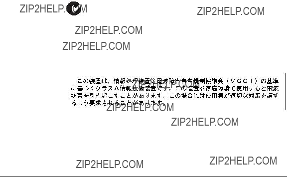
Japan
VCCI Class A
27

Switch Overview
EMC Regulatory Statements
Korea
Taiwan
28
Switch Overview
EMC Regulatory Statements
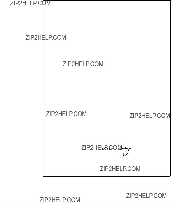
European Community Declaration of Conformity
declares that the product:
Product Name: ProCurve Switch
Model Number: J9019A
Accessories: J4858B, J4859B, J4860B
Regulatory Model Number:
conforms to the following Product Specifications:
Safety: EN60950:2001 / IEC 60950:1999
EMC: EN 55022: 1998+A1:2000+A2:2003 /
EN
Supplementary Information:
The product herewith complies with the requirements of the Low Voltage Directive 73/23/EEC and the EMC Directive 89/336/EEC and carries the CE marking accordingly.
Tested with
Roseville, California
June 22, 2006
Mike Avery,
Regulatory Engineering Manager
European Contact: Your local
29
Switch Overview
Recycle Statements
Recycle Statements
Waste Electrical and Electronic
Equipment (WEEE) Statements
Disposal of Waste Equipment by Users in Private Household in the European Union
This symbol on the product or on its packaging indicates that this product must not be disposed of with your other household waste. Instead, it is your responsibility to dispose of your waste equipment by handing it over to a designated collection point for the recycling of waste electrical and electronic equipment. The separate collection and recycling of your waste equipment at the time of disposal will help to conserve natural resources and ensure that it is recycled in a manner that protects human health and the environment. For more information about where you can drop off your waste equipment for recycling, please contact your local city office, your household waste disposal service or the shop where you purchased the product.
Likvidace za????zen?? soukrom??mi dom??c??mi u??ivateli v Evropsk?? unii
Tento symbol na produktu nebo balen?? ozna??uje v??robek, kter?? nesm?? b??t vyhozen spolu s ostatn??m dom??c??m odpadem. Povinnost?? u??ivatele je p??edat takto ozna??en?? odpad na p??edem ur??en?? sb??rn?? m??sto pro recyklaci elektrick??ch a elektronick??ch za????zen??. Okam??it?? t????d??n?? a recyklace odpadu pom????e uchovat p????rodn?? prost??ed?? a zajist?? takov?? zp??sob recyklace, kter?? ochr??n?? zdrav?? a ??ivotn?? prost??ed?? ??lov??ka. Dal???? informace o mo??nostech odevzd??n?? odpadu k recyklaci z??sk??te na p????slu??n??m obecn??m nebo m??stsk??m ????ad??, od firmy zab??vaj??c?? se sb??rem a svozem odpadu nebo v obchod??, kde jste produkt zakoupili.
Bortskaffelse af affald fra husstande i den Europ??iske Union
Hvis produktet eller dets emballage er forsynet med dette symbol, angiver det, at produktet ikke m?? bortskaffes med andet almindeligt husholdningsaffald. I stedet er det dit ansvar at bortskaffe kasseret udstyr ved at aflevere det p?? den kommunale genbrugsstation, der forest??r genvinding af kasseret elektrisk og elektronisk udstyr. Den centrale modtagelse og genvinding af kasseret udstyr i forbindelse med bortskaffelsen bidrager til bevarelse af naturlige ressourcer og sikrer, at udstyret genvindes p?? en m??de, der beskytter b??de mennesker og milj??. Yderligere oplysninger om, hvor du kan aflevere kasseret udstyr til genvinding, kan du f?? hos kommunen, den lokale genbrugsstation eller i den butik, hvor du k??bte produktet.
Seadmete j????tmete k??rvaldamine eramajapidamistes Euroopa Liidus
See tootel v??i selle pakendil olev s??mbol n??itab, et k??nealust toodet ei tohi koos teiste majapidamisj????t- metega k??rvaldada. Teie kohus on oma seadmete j????tmed k??rvaldada, viies need elektri- ja elektrooni- kaseadmete j????tmete ringlussev??tmiseks selleks etten??htud kogumispunkti. Seadmete j????tmete eraldi kogumine ja ringlussev??tmine k??rvaldamise ajal aitab kaitsta loodusvarasid ning tagada, et ringlussev- ??tmine toimub viisil, mis kaitseb inimeste tervist ning keskkonda. Lisateabe saamiseks selle kohta, kuhu oma seadmete j????tmed ringlussev??tmiseks viia, v??tke palun ??hendust oma kohaliku linnakantselei, majapidamisj????tmete k??rvaldamise teenistuse v??i kauplusega, kust Te toote ostsite.
30

Switch Overview
Waste Electrical and Electronic Equipment (WEEE) Statements
Laitteiden h??vitt??minen kotitalouksissa Euroopan unionin alueella
Jos tuotteessa tai sen pakkauksessa on t??m?? merkki, tuotetta ei saa h??vitt???? kotitalousj??tteiden mukana. T??ll??in h??vitett??v?? laite on toimitettava s??hk??laitteiden ja elektronisten laitteiden kierr??tyspisteeseen. H??vitett??vien laitteiden erillinen k??sittely ja kierr??tys auttavat s????st??m????n luonnonvaroja ja varmistamaan, ett?? laite kierr??tet????n tavalla, joka est???? terveyshaitat ja suojelee luontoa. Lis??tietoja paikoista, joihin h??vitett??v??t laitteet voi toimittaa kierr??tett??v??ksi, saa ottamalla yhteytt?? j??tehuoltoon tai liikkeeseen, josta tuote on ostettu.
??limination des appareils mis au rebut par les m??nages dans l'Union europ??enne
Le symbole appos?? sur ce produit ou sur son emballage indique que ce produit ne doit pas ??tre jet?? avec les d??chets m??nagers ordinaires. Il est de votre responsabilit?? de mettre au rebut vos appareils en les d??posant dans les centres de collecte publique d??sign??s pour le recyclage des ??quipements ??lectriques et ??lectroniques. La collecte et le recyclage de vos appareils mis au rebut ind??pendamment du reste des d??chets contribue ?? la pr??servation des ressources naturelles et garantit que ces appareils seront recycl??s dans le respect de la sant?? humaine et de l'environnement. Pour obtenir plus d'informations sur les centres de collecte et de recyclage des appareils mis au rebut, veuillez contacter les autorit??s locales de votre r??gion, les services de collecte des ordures m??nag??res ou le magasin dans lequel vous avez achet?? ce produit.
Entsorgung von Altger??ten aus privaten Haushalten in der EU
Das Symbol auf dem Produkt oder seiner Verpackung weist darauf hin, dass das Produkt nicht ??ber den normalen Hausm??ll entsorgt werden darf. Benutzer sind verpflichtet, die Altger??te an einer R??cknah- mestelle f??r Elektro- und
???????????????? ???????????????? ???????????????????? ?????? ?????????????? ???? ???????????????? ???????????????????? ???????? ?????????????????? ??????????
???? ?????????????? ???????? ?????? ???????????? ?? ???? ???????????????????? ?????? ?????????????????????? ?????? ???? ???????????????????????? ???????????? ?????? ???????????? ???? ???????????????????? ???????? ???? ???? ???????? ?????????????? ?????? ??????????????????????. ????????????????, ?????????? ???????? ?????? ???????????? ???? ???????????????????? ?????? ?????????????? ?????????????????? ?????? ???????????????????????? ?????? ???? ?????????????????????? ???????????? ???????????????? ?????? ?????? ???????????????????? ???????????????? ???????????????????? ?????? ???????????????????????? ????????????????????. ?? ?????????????????? ?????????????? ?????? ???????????????????? ?????? ???????????????? ???????????????????? ?????? ???????? ?????? ???????????????? ???? ???????????????? ?????? ?????????????????? ?????? ?????????????? ?????????? ?????? ???? ?????????????????????? ?????? ?? ???????????????????? ?????????????? ???? ?????????? ?????? ?????????????????????? ?????? ?????????????????? ?????????? ?????? ???? ????????????????????. ?????? ???????????????????????? ?????????????????????? ?????????????? ???? ???? ?????? ???????????????? ???? ???????????????????? ?????? ?????????????? ?????????????????? ?????? ?????? ????????????????????, ?????????????????????????? ???? ???? ?????????????? ???????????? ??????????????, ?????? ???????????? ???????????????? ???????????????? ???????????????? ???????????????????????? ?? ???? ?????????????????? ???????? ?????????????????? ???? ????????????.
K??sz??l??kek mag??nh??ztart??sban t??rt??n?? selejtez??se az Eur??pai Uni?? ter??let??n
A k??sz??l??ken, illetve a k??sz??l??k csomagol??s??n l??that?? azonos szimb??lum annak jelz??s??re szolg??l, hogy a k??sz??l??k a selejtez??s sor??n az egy??b h??ztart??si hullad??kt??l elt??r?? m??don kezelend??. A v??s??rl?? a hullad??kk?? v??lt k??sz??l??ket k??teles a kijel??lt gy??jt??helyre sz??ll??tani az elektromos ??s elektronikai k??sz??l??kek ??jrahasznos??t??sa c??lj??b??l. A hullad??kk?? v??lt k??sz??l??kek selejtez??skori begy??jt??se ??s ??jrahasznos??t??sa hozz??j??rul a term??szeti er??forr??sok meg??rz??s??hez, valamint biztos??tja a selejtezett term??kek k??rnyezetre ??s emberi eg??szs??gre n??zve biztons??gos feldolgoz??s??t. A begy??jt??s pontos hely??r??l b??vebb t??j??koztat??st a lakhelye szerint illet??kes ??nkorm??nyzatt??l, az illet??kes szem??teltakar??t?? v??llalatt??l, illetve a term??ket el??rus??t?? helyen kaphat.
31
Switch Overview
Waste Electrical and Electronic Equipment (WEEE) Statements
Smaltimento delle apparecchiature da parte di privati nel territorio dell'Unione Europea
Questo simbolo presente sul prodotto o sulla sua confezione indica che il prodotto non pu?? essere smaltito insieme ai rifiuti domestici. ?? responsabilit?? dell'utente smaltire le apparecchiature consegnan- dole presso un punto di raccolta designato al riciclo e allo smaltimento di apparecchiature elettriche ed elettroniche. La raccolta differenziata e il corretto riciclo delle apparecchiature da smaltire permette di proteggere la salute degli individui e l'ecosistema. Per ulteriori informazioni relative ai punti di raccolta delle apparecchiature, contattare l'ente locale per lo smaltimento dei rifiuti, oppure il negozio presso il quale ?? stato acquistato il prodotto.
Nolietotu iek??rtu izn??cin????anas noteikumi lietot??jiem Eiropas Savien??bas priv??taj??s m??jsaimniec??b??s
????ds simbols uz izstr??d??juma vai uz t?? iesai??ojuma nor??da, ka ??o izstr??d??jumu nedr??kst izmest kop?? ar citiem sadz??ves atkritumiem. J??s atbildat par to, lai nolietot??s iek??rtas tiktu nodotas speci??li iek??rtotos punktos, kas paredz??ti izmantoto elektrisko un elektronisko iek??rtu sav??k??anai otrreiz??jai p??rstr??dei. Atsevi????a nolietoto iek??rtu sav??k??ana un otrreiz??j?? p??rstr??de pal??dz??s saglab??t dabas resursus un garant??s, ka ????s iek??rtas tiks otrreiz??ji p??rstr??d??tas t??d?? veid??, lai pasarg??tu vidi un cilv??ku vesel??bu. Lai uzzin??tu, kur nolietot??s iek??rtas var izmest otrreiz??jai p??rstr??dei, j??v??r??as savas dz??ves vietas pa??vald??b??, sadz??ves atkritumu sav??k??anas dienest?? vai veikal??, kur?? izstr??d??jums tika nopirkts.
Vartotoj?? i?? priva??i?? nam?? ??ki?? ??rangos atliek?? ??alinimas Europos S??jungoje
??is simbolis ant gaminio arba jo pakuot??s rodo, kad ??io gaminio ??alinti kartu su kitomis nam?? ??kio atliekomis negalima. ??alintinas ??rangos atliekas privalote pristatyti ?? speciali?? surinkimo viet?? elektros ir elektronin??s ??rangos atliekoms perdirbti. Atskirai surenkamos ir perdirbamos ??alintinos ??rangos atliekos pad??s saugoti gamtinius i??teklius ir u??tikrinti, kad jos bus perdirbtos tokiu b??du, kuris nekenkia ??moni?? sveikatai ir aplinkai. Jeigu norite su??inoti daugiau apie tai, kur galima pristatyti perdirbtinas ??rangos atliekas, kreipkit??s ?? savo seni??nij??, nam?? ??kio atliek?? ??alinimo tarnyb?? arba parduotuv??, kurioje ??sigijote gamin??.
Verwijdering van afgedankte apparatuur door
Dit symbool op het product of de verpakking geeft aan dat dit product niet mag worden gedeponeerd bij het normale huishoudelijke afval. U bent zelf verantwoordelijk voor het inleveren van uw afgedankte apparatuur bij een inzamelingspunt voor het recyclen van oude elektrische en elektronische apparatuur. Door uw oude apparatuur apart aan te bieden en te recyclen, kunnen natuurlijke bronnen worden behouden en kan het materiaal worden hergebruikt op een manier waarmee de volksgezondheid en het milieu worden beschermd. Neem contact op met uw gemeente, het afvalinzamelingsbedrijf of de winkel waar u het product hebt gekocht voor meer informatie over inzamelingspunten waar u oude apparatuur kunt aanbieden voor recycling.
Pozbywanie si?? zu??ytego sprz??tu przez u??ytkownik??w w prywatnych gospodarstwach domowych w Unii Europejskiej
Ten symbol na produkcie lub jego opakowaniu oznacza, ??e produktu nie wolno wyrzuca?? do zwyk??ych pojemnik??w na ??mieci. Obowi??zkiem u??ytkownika jest przekazanie zu??ytego sprz??tu do wyznaczonego punktu zbi??rki w celu recyklingu odpad??w powsta??ych ze sprz??tu elektrycznego i elektronicznego. Osobna zbi??rka oraz recykling zu??ytego sprz??tu pomog?? w ochronie zasob??w naturalnych i zapewni?? ponowne wprowadzenie go do obiegu w spos??b chroni??cy zdrowie cz??owieka i ??rodowisko. Aby uzyska?? wi??cej informacji o tym, gdzie mo??na przekaza?? zu??yty sprz??t do recyklingu, nale??y si?? skontaktowa?? z urz??dem miasta, zak??adem gospodarki odpadami lub sklepem, w kt??rym zakupiono produkt.
32

Switch Overview
Waste Electrical and Electronic Equipment (WEEE) Statements
Descarte de Lixo El??trico na Comunidade Europ??ia
Este s??mbolo encontrado no produto ou na embalagem indica que o produto n??o deve ser descartado no lixo dom??stico comum. ?? responsabilidade do cliente descartar o material usado (lixo el??trico),
Likvid??cia vyraden??ch zariaden?? v dom??cnostiach v Eur??pskej ??nii
Symbol na v??robku alebo jeho balen?? ozna??uje, ??e dan?? v??robok sa nesmie likvidova?? s domov??m odpadom. Povinnos??ou spotrebite??a je odovzda?? vyraden?? zariadenie v zbernom mieste, ktor?? je ur??en?? na recykl??ciu vyraden??ch elektrick??ch a elektronick??ch zariaden??. Separovan?? zber a recykl??cia vyraden??ch zariaden?? prispieva k ochrane pr??rodn??ch zdrojov a zabezpe??uje, ??e recykl??cia sa vykon??va sp??sobom chr??niacim ??udsk?? zdravie a ??ivotn?? prostredie. Inform??cie o zbern??ch miestach na recykl??ciu vyraden??ch zariaden?? v??m poskytne miestne zastupite??stvo, spolo??nos?? zabezpe??uj??ca odvoz domov??ho odpadu alebo obchod, v ktorom ste si v??robok zak??pili.
Odstranjevanje odslu??ene opreme uporabnikov v zasebnih gospodinjstvih v Evropski uniji
Ta znak na izdelku ali njegovi embala??i pomeni, da izdelka ne smete odvre??i med gospodinjske odpadke. Nasprotno, odslu??eno opremo morate predati na zbirali????e, poobla????eno za recikliranje odslu??ene elektri??ne in elektronske opreme. Lo??eno zbiranje in recikliranje odslu??ene opreme prispeva k ohranjanju naravnih virov in zagotavlja recikliranje te opreme na zdravju in okolju ne??kodljiv na??in. Za podrobnej??e informacije o tem, kam lahko odpeljete odslu??eno opremo na recikliranje, se obrnite na pristojni organ, komunalno slu??bo ali trgovino, kjer ste izdelek kupili.
Eliminaci??n de residuos de equipos el??ctricos y electr??nicos por parte de usuarios particulares en la Uni??n Europea
Este s??mbolo en el producto o en su envase indica que no debe eliminarse junto con los desperdicios generales de la casa. Es responsabilidad del usuario eliminar los residuos de este tipo deposit??ndolos en un "punto limpio" para el reciclado de residuos el??ctricos y electr??nicos. La recogida y el reciclado selectivos de los residuos de aparatos el??ctricos en el momento de su eliminaci??n contribuir?? a conservar los recursos naturales y a garantizar el reciclado de estos residuos de forma que se proteja el medio ambiente y la salud. Para obtener m??s informaci??n sobre los puntos de recogida de residuos el??ctricos y electr??nicos para reciclado, p??ngase en contacto con su ayuntamiento, con el servicio de eliminaci??n de residuos dom??sticos o con el establecimiento en el que adquiri?? el producto.
Bortskaffande av avfallsprodukter fr??n anv??ndare i privathush??ll inom Europeiska Unionen
Om den h??r symbolen visas p?? produkten eller f??rpackningen betyder det att produkten inte f??r sl??ngas p?? samma st??lle som hush??llssopor. I st??llet ??r det ditt ansvar att bortskaffa avfallet genom att ??verl??mna det till ett uppsamlingsst??lle avsett f??r ??tervinning av avfall fr??n elektriska och elektroniska produkter. Separat insamling och ??tervinning av avfallet hj??lper till att spara p?? v??ra naturresurser och g??r att avfallet ??tervinns p?? ett s??tt som skyddar m??nniskors h??lsa och milj??n. Kontakta ditt lokala kommunkontor, din n??rmsta ??tervinningsstation f??r hush??llsavfall eller aff??ren d??r du k??pte produkten f??r att f?? mer information om var du kan l??mna ditt avfall f??r ??tervinning.
33

Technical information in this document is subject to change without notice.
??? Copyright
Printed in Taiwan
June 2006
Manual Part Number