HP 8360 Series Synthesized Sweepers (Including Options 001, 003, 004, 006, and 008)
User???s Handbook
SERIAL NUMBERS
This manual applies directly to any synthesized sweeper with serial number prefix combinations. You may have to modify this manual so that it applies directly to your instrument version. Refer to the ???Instrument History??? chapter.
HP Part No. 08380-90070
Microfiche Part No. 08380-90073
Printed in USA November 1995
Edition 9
Notice
Restricted Rights
Legend
The information contained in this document is subject to change without notice.
Hewlett-Packard makes no warranty of any kind with regard to this material, including but not limited to, the implied warranties of merchantability and fitness for a particular purpose. Hewlett-Packard shall not be liable for errors contained herein or for incidental
or consequential damages in connection with the furnishing, performance, or use of this material.
Use, duplication, or disclosure by the U.S. Government is subject to restrictions as set forth in subparagraph (c) (1) (ii) of the
Rights of Technical Data and Computer Software clause at DFARS 252.227-7013 for DOD agencies, and subparagraphs (c) (1) and
(c) (2) of the Commercial Computer Software Restricted Rights clause at FAR 52.227-19 for other agencies.
@ Copyright Hewlett-Packard Company 1992, 1995
All Rights Reserved. Reproduction, adaptation, or translation without prior written permission is prohibited, except as allowed under the copyright laws.
1400 Fountaingrove Parkway, Santa Rosa, CA 95403-1799, USA

Hewlett-Packard Company certifies that this product met its published specifications at the time of shipment from the factory. Hewlett-Packard further certifies that its calibration measurements are traceable to the United States National Institute of Standards and Technology, to the extent allowed by the Institute???s calibration facility, and to the calibration facilities of other International Standards Organization members.
This Hewlett-Packard instrument product is warranted against defects in material and workmanship for a period of one year from date of shipment. During the warranty period, Hewlett-Packard Company will, at its option, either repair or replace products which prove to be defective.
For warranty service or repair, this product must be returned to a service facility designated by Hewlett-Packard. Buyer shall prepay shipping charges to Hewlett-Packard and Hewlett-Packard shall pay shipping charges to return the product to Buyer. However, Buyer shall pay all shipping charges, duties, and taxes for products returned to Hewlett-Packard from another country.
Hewlett-Packard warrants that its software and firmware designated by Hewlett-Packard for use with an instrument will execute
its programming instructions when properly installed on that instrument. Hewlett-Packard does not warrant that the operation of the instrument, or software, or firmware will be uninterrupted or error-free.
LIMITATION OF WARRANTY
The foregoing warranty shall not apply to defects resulting from improper or inadequate maintenance by Buyer, Buyer-supplied software or interfacing, unauthorized modification or misuse, operation outside of the environmental specifications for the product, or improper site preparation or maintenance.
NO OTHER WARRANTY IS EXPRESSED OR IMPLIED.
HEWLETT-PACKARD SPECIFICALLY DISCLAIMS THE
IMPLIED WARRANTIES OF MERCHANTABILITY AND
FITNESS FOR A PARTICULAR PURPOSE.
EXCLUSIVE REMEDIES
THE REMEDIES PROVIDED HEREIN ARE BUYER???S SOLE
AND EXCLUSIVE REMEDIES. HEWLETT-PACKARD SHALL
NOT BE LIABLE FOR ANY DIRECT, INDIRECT, SPECIAL,
INCIDENTAL, OR CONSEQUENTIAL DAMAGES, WHETHER
BASED ON CONTRACT, TORT, OR ANY OTHER LEGAL
THEORY.
Assistance
Safety Notes
WARNING
CAUTION
Product maintenance agreements and other customer assistance agreements are available for Hewlett-Packard products. For any assistance, contact your nearest Hewlett-Packard Sales and Service Ofice.
The following safety notes are used throughout this manual. Familiarize yourself with each of the notes and its meaning before operating this instrument.
Warning denotes a hazard. It calls attention to a procedure which, if not correctly performed or adhered to, could result in injury or loss of life. Do not proceed beyond a warning note until the indicated conditions are fully understood and met.
Caution denotes a hazard. It calls attention to a procedure that, if not correctly performed or adhered to, would result in damage to or destruction of the instrument. Do not proceed beyond a caution sign until the indicated conditions are fully understood and met.

General Safety
Considerations
WARNING
??? No operator serviceable parts inside. Refer servicing to qualified personnel. To prevent electrical shock, do not remove covers.
nFor continued protection against fire hazard replace line fuse only with same type and rating (F 5A/25OV). The use of other fuses or material is prohibited.
nThis is a Safety Class I product (provided with a protective earthing ground incorporated in the power cord). The mains plug shall only be inserted in a socket outlet provided with a protective earth contact. Any interruption of the protective conductor, inside or outside the instrument, is likely to make the instrument dangerous. Intentional interruption is prohibited.
nThis is a Safety Class I product (provided with a protective earthing ground incorporated in the power cord). The mains plug shall only be inserted in a socket outlet provided with a protective earth contact. Any interruption of the protective conductor, inside or outside the instrument, is likely to make the instrument dangerous. Intentional interruption is prohibited.
nIf this instrument is used in a manner not specified by
Hewlett-Packard Co., the protection provided by the instrument may be impaired. This product must be used in a normal condition (in which all means for protection are intact) only.

PREFACE
Instruments Covered
By This Manual
This manual provides user information for the HP 8360 Series Synthesized Sweepers.
This manual applies to instruments having a serial number prefix listed on the title page (behind the ???Documentation Map??? tab). Some changes may have to be made to this manual so that it applies directly to each instrument; refer to Chapter 5, ???Instrument History???, to see what changes may apply to your instrument.
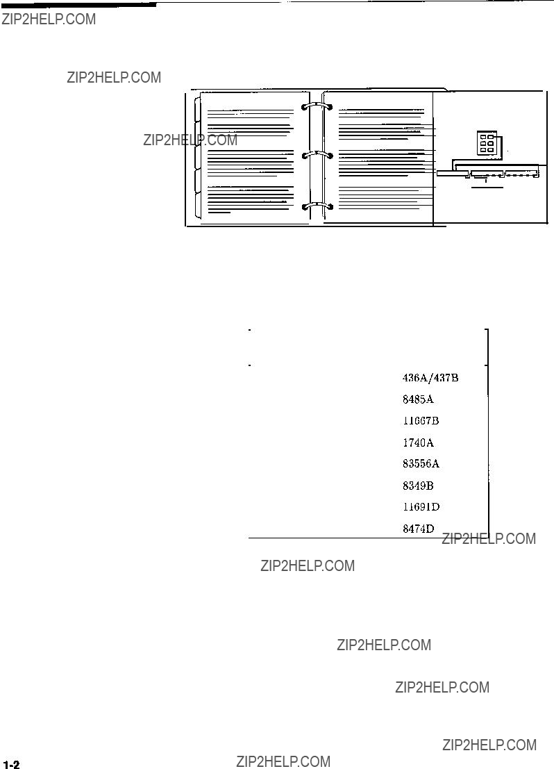
A serial number label (Figure O-l) is attached to the instrument???s rear panel. A prefix (four digits followed by a letter), and a suffix (five digits unique to each instrument), comprise the instrument serial number.
SERIAL NUMBER
INSTALLED
OPTIONS
Figure O-l. Typical Serial Number Label
An instrument???s prefix that is not listed on the title page may indicate that the instrument is different from those documented in this manual. For serial number prefixes before those listed on the title page, refer to the HP 8360 Series Synthesized
Sweepers Instrument History (to order, see ???Replaceable Parts??? in
Assembly-Level Repair).
User???s Handbook
Organization
HP 8360 Series
Documentation
Typeface
Conventions
Tabs divide the major chapters of this manual. The contents of each chapter is listed in the ???Table of Contents.???
Documentation Map
For a pictorial representation of the HP 8360 series documentation, see the ???Documentation Map??? at the front of this manual.
Ordering Manual
A manual part number is listed on the title page of this manual. You may use it to order extra copies of this manual. See ???Replaceable Parts??? in Assembly-Level Repair for a complete list of HP 8360 documentation and ordering numbers.
The following conventions are used in the HP 8360 series documentation:
Italics Italic type is used for emphasis, and for titles of manuals and other publications.
Computer Computer type is used for information displayed on the instrument. For example: In this sequence, POWER LEVEL is displayed.
(-1 Instrument keys are represented in ???key cap.??? You are instructed to press a hardkey.
Softkeys Softkeys are located just below the display, and their functions depend on the current display. These keys are represented in ???softkey.??? You are instructed to select a softkey.

Regulatory
Information
Manufacturer???s
Declaration
Note
Note
This product has been designed and tested in accordance with IEC Publication 1010, Safety Requirements for Electronic Measuring Apparatus, and has been supplied in a safe condition. The instruction documentation contains information and warnings which must be followed by the user to ensure safe operation and to maintain the instrument in a safe condition.
This is to certify that this product meets the radio frequency interference requirements of Directive FTZ 1046/1984. The German Bundespost has been notified that this equipment was put into circulation and has been granted the right to check the product type for compliance with these requirements.
Note: If test and measurement equipment is operated with unshielded cables and/or used for measurements on open set-ups, the user must insure that under these operating conditions, the radio frequency interference limits are met at the border of his premises.
Model HP 8360 Series Synthesized Sweepers
Hiermit wird bescheinigt, dass dieses Gerat/System in Ubereinstimmung mit den Bestimmungen von Postverfiigung 1046/84 funkentstijrt ist .
Der Deutschen Bundespost wurde das Inverkehrbringen dieses GerHtes/Systems angezeight und die Berechtigung zur fiberpriifung der Serie auf Einhaltung der Bestimmungen eingeraumt.
Zustzinformation fur Mess-und Testgerate:
Werden Mess- und Testgerate mit ungeschirmten Kabeln und/oder in offenen Messaufbauten verwendet, so ist vom Betreiber sicherzustellen, dass die Funk-Entstorbestimmungen unter Betriebsbedingungen an seiner Grundstiicksgrenze eingehalten werden.
Notice for Germany: Noise Declaration
LpA < 70 dB
am Arbeitsplatz (operator position) normaler Betrieb (normal position) nach DIN 45635 T. 19 (per IS0 7779)
Declaration of
Conformity
DECLARATION OF CONFORMITY
accor&g to ISOIIEC Quide 22 and EN 45014
Manufacturer???s Name:
Manufacturer???s Address:
declares that the product
Product Name:
Model Numbers:
Hewlett-Packard Co.
Microwave Instruments Division
1400 Fountaingrove Parkway
Santa Rosa, CA 95403-1799
USA
Synthesized Sweeper
HP 8362OA, HP 8362lA, HP 83622A, HP 83623A, HP 83624A, HP 8363OA, HP 8363lA, HP 8364OA, HP 36642A, HP 8365OA, HP 83651A
conforms to the following Product specifications:
Safety: IEC 348:1978/HD 401 Sl:l981
CANZSA-C22.2 No. 231 (Series M-89)
EMC: ClSPR 11:199O/EN 55011:1991 Group 1, Class A /EC 801-2:1984/EN 50082-1:1992 4 kV CD, 8 kVAD /EC 801-3:1984/EN 50082-1:1992 3 V/m, 27-500 MHz
/EC 80 f-4: 1988/EN 50082- 1: 1992 0.5 kV Sig. Lines, 1 kV Power Lines
Supplementary Information:
The product herewith complies with the requirements of the Low Voltage Directive 73/23/EEC and the EMC Directive 89/336/EEC.
Santa Rosa, California, USA 2 Oct. 1995
European Contact: Your local Hewlett-Packard &/es and Service Office or Hewlett-Packard QmbH, Department HQ-TRE, Herrenberger Sttasse 130, D-71034 Biiblingen Germany(FAX+4&7031-163143)
Instrument MarkingsA!
Cd
???ISMl-A???
I
I
0
I
The instruction documentation symbol. The product is marked with this symbol when it is necessary for the user to refer to the instructions in the documentation.
The CE mark is a registered trademark of the European Community.
The CSA mark is a registered trademark of the Canadian Standards Association.
This is a symbol of an Industrial Scientific and Medical Group 1 Class A product.
This is an ON symbol. The symbol ON is used to mark the position of the instrument power line switch.
This is an ON symbol. The symbol ON is used to mark the position of the instrument power line switch.
This is a STANDBY symbol. The STANDBY symbol is used to mark the position of the instrument power line switch.
This is an OFF symbol. The OFF symbol is used to mark the position of the instrument power line switch.
This is an AC symbol. The AC symbol is used to indicate the required nature of the line module input power.
Hewlett-Packard Sales and Service Offices
US FIELD OPERATIONS
Headquarters
Hewlett-Packard Co.
19320 Pruneridge Avenue
Cupertino, CA 95014
(800) 752-0900
Colorado
Hewlett-Packard Co.
24 Inverness Place, East
Englewood, CO 80112
(303) 649-5512
New Jersey
Hewlett-Packard Co.
150 Green Pond Rd.
Rockaway, NJ 07866
(201) 586-5400
HP 8360
User???s Handbook
1.GETTING STARTED
Contents-l
HP 8360
User???s Handbook

Programming the Trigger System . . . . . . . . .
In This Subsection . . . . . . . . . . . . . .
Generalized Trigger Model . . . . . . . . . . .
Overview . . . . . . . . . . . . . . . . .
Details of Trigger States . . . . . . . . . . .
Inside the Idle State . . . . . . . . . . .
Inside the Initiate State . . . . . . . . . .
Inside Event Detection States . . . . . . .
Inside the Sequence Operation State . . . .
Common Trigger Configurations . . . . . . . .
The INIT Configuration . . . . . . . . . . .
The TRIG Configuration . . . . . . . . . .
Description of Triggering in the HP 8360 Series Synthesizers . . . . . . . . . . . . . . .
Advanced Trigger Configurations . . . . . . .
Trigger Keyword Definitions . . . . . . . . . .
ABORt . . . . . . . . . . . . . . . . . .
IMMediate . . . . . . . . . . . . . . . .
ODELay . . . . . . . . . . . . . . . . .
SOURce . . . . . . . . . . . . . . . . . .
Related Documents . . . . . . . . . . . . . . .
The International Institute of Electrical and Electronics Engineers. . . . . . . . . . . .
Hewlet t-Packard Company . . . . . . . . . . .
2.OPERATING AND PROGRAMMING REFERENCE How To Use This Chapter . . . . . . . . . . . .
A.
l-104 l-104 l-104 l-104 l-105 l-105 l-106 l-107 l-109 l-109 l-109 l-110
l-111 1-112 1-112 1-113 1-113 1-113 1-113 1-114
1-114 l-114
2-l
HP 8360
User???s Handbook
E.
8360 Adz-s . . . . . . . . . . . . . . . . . .
Enter Cum . . . . . . . . . . . . . . . . . .
EnterFreq . . . . . . . . . . . . . . . . . .
Enter List Dwell . . . . . . . . . . . . . .
Enter List Freq . . . . . . . . . . . . . . .
Enter List Offset . . . . . . . . . . . . . .
ENTRY KEYS . . . . . . . . . . . . . . . . .
[ENTR~~N/OFF] . . . . . . . . . . . . . . . . .
ExtDetCal . . . . . . . . . . . . . . . . .
F.
E-l E-l E-2 E-2 E-3 E-4 E-4 E-5 E-5
Leveling ModeALCoff . . . . . . . . . . . . .
Leveling ModeNormal . . . . . . . . . . . . .
Leveling ModeSearch . . . . . . . . . . . . .
Leveling PointExtDet . . . . . . . . . . . .
Leveling Pointlntml . . . . . . . . . . . .
Leveling PointModule . . . . . . . . . . . .
Leveling PointPwrMtr . . . . . . . . . . . .
LINE SWITCH . . . . . . . . . . . . . . . .
ListMenu . . . . . . . . . . . . . . . . . .
List Mode Pt TrigAuto . . . . . . . . . . . .
List Mode Pt TrigBus . . . . . . . . . . . .
List Mode Pt TrigExt . . . . . . . . . . . .
(LOCAL)
. . . . . . . . . . . . . . . . . . . . .
L-l
L-2
L-2
L-3
L-3
L-4
L-4 L-5 L-5
L-8
L-8
L-9 L-9

M.
MI--M2 Sweep . . . . . . . . . .  : . . . . . .
Manual Sweep . . . . . . . . . . . . . . . . .
(MARKER)
. . . . . . . . . . . . . . . . . . . .
MarkerMi . . . . . . . . . . . . . . . . . .
Marker M2 . . . . . . . . . . . . . . . . . .
MarkerM3 . . . . . . . . . . . . . . . . . .
Marker M4 . . . . . . . . . . . . . . . . . .
MarkerM5 . . . . . . . . . . . . . . . . . .
Markers All Off . . . . . . . . . . . . . . .
Measure Corx All . . . . . . . . . . . . . .
Measure Corr Current . . . . . . . . . . . .
Measure Corr Undef . . . . . . . . . . . . .
Meter Adxs . . . . . . . . . . . . . . . . . .
Meter On/Off AM . . . . . . . . . . . . . . .
Meter On/Off FM . . . . . . . . . . . . . . .
@ . . . . . . . . . . . . . . . . . . . . .
ModOut On/Off API . . . . . . . . . . . . . .
ModOut On/Off FM . . . . . . . . . . . . . .
Modulation . . . . . . . . . . . . . . . . . .
Amplitude Modulation . . . . . . . . . . . . .
FMModulation . . . . . . . . . . . . . . . .
Pulse Modulation . . . . . . . . . . . . . . . .
Module Menu . . . . . . . . . . . . . . . . .
Module Select AUTO . . . . . . . . . . . . .
Module Select Front . . . . . . . . . . . . .
Module Select None . . . . . . . . . . . . .
Module Select Rear . . . . . . . . . . . . .
Monitor Menu . . . . . . . . . . . . . . . . .
morenfm.. . . . . . . . . . . . . . . . . .
Mtr Meas Menu . . . . . . . . . . . . . . . .
P.
Peak RF Always . . . . . . . . . . . . . . . .
PeakRFOnce . . . . . . . . . . . . . . . . .
(POWER L E V E L ) . . . . . . . . . . . . . . . . .
POWER(E)
. . . . . . . . . . . . . . . . .
Pawer Offset . . . . . . . . . . . . . . . . .
Power Slope . . . . . . . . . . . . . . . . .
Power Sweep . . . . . . . . . . . . . . . . .
;w)(PRESET) . .- . . . . . . . . . . . . . . . . . .
. . . . . . . . . . . . . . . . . . . . . .
Preset Mode Factory . . . ............ . . . .
Preset Mode User . . . . . . ........... . . .
M-l M-l M-3 M-4 M-5 M-5 M-6 M-6 M-7 M-7 M-8 M-8 M-9 M-9 M-10 M-10 M-11 M-12 M-12 M-14 M-17 M-19 M-23 M-24 M-24 M-25 M-26 M-26 M-27 M-28
P-l P-2 P-2 P-5 P-6 P-6 P-7 P-8 P-9 P-10
HP 8360
User???s Handbook

. . . . . . . . . . .
...........
...........
 .
.  .
.  .
.  .
.  .
.  .
.  .
.  .
.  .
.  .
.  .
.
 .
.  .
.  .
.  .
.  .
.  .
.  .
.  .
.  .
.  .
.  .
.
. . . . . . . . . . .
 .
.  .
.  .
.  .
.  .
.  .
.  .
.  .
.  .
.  .
.  .
.
...........
...........
...........
...........
...........
 .
.  .
.  .
.  .
.  .
.  .
.  .
.  .
.  .
.  .
.  .
.
...........
...........
...........
...........
T.
10 MHz Freq Std Auto . . . . . . . . . . . .
10 MHz Freq Std Exts-nl . . . . . . . . . . .
10 MHz Freq Std Intrnl . . . . . . . . . . .
10 MHz Freq Std None . . . . . . . . . . . .
Tracking Menu . . . . . . . . . . . . . . . .
TrigOut Delay . . . . . . . . . . . . . . . .
U.
Uncoupl Atten . . . . . . . . . . . . . . . .
Unlock Info . . . . . . . . . . . . . . . . .
Up/Down Power . . . . . . . . . . . . . . . .
Up]Dn Size CW . . . . . . . . . . . . . . . .
Up/Dn Size Swept . . . . . . . . . . . . . .
[UsER).
. . . . . . . . . . . . . . . . . . .
USER DEFINED [MENU)
. . . . . . . . . . . . .
UsrKey Clear . . . . . . . . . . . . . . . . .
UsrMenu Clear . . . . . . . . . . . . . . . .
S-64 S-64 S-66 S-67 S-67 S-68 S-69 s-70 s-70 s-71 s-71 S-72 s-73 s-73 s-74 s-75 s-75 S-76 S-76 s-77
T - l T - l T-2 T-2 T-3 T-3
U-l U-l u-2 u-2 u-3 u-4 u-4 u-5 u-5
HP 8360
User???s Handbook
HP 8360
User???s Handbook
3.INSTALLATION
Contents-13
Test and Measurement System Language . . .
Control Interface Intermediate Language . . .
Converting from Network Analyzer Language to SCPI . . . . . . . . . . . . . . . . . .
Numeric Suffixes . . . . . . . . . . . . . .
Status Bytes . . . . . . . . . . . . . . . .
HP 8360
User???s Handbook
What Is In This
Chapter
Note
This chapter contains information on how to use the HP 8360 Series Synthesized Sweeper. The information is separated into three sections.
BasicFor the novice user unfamiliar with the HP 8360 Series Synthesized Sweepers. This section describes the basic features of the synthesizer.
AdvancedFor the user familiar with synthesizers, but not necessarily familiar with how to use the special features of the HP 8360 series.
Programming For the user wishing to program an HP 8360 Series Synthesized Sweeper. This section contains an introduction to Standard Commands for Programmable Instruments language
(SCPI), Hewlett-Packard???s implementation of IEEE-488.2-1987, and an introduction to the Analyzer programming language.
If you are unpacking a new synthesizer, refer to the installation suggestions provided in the ???INSTALLATION??? chapter of this manual.
Getting Started Introduction l-1
To use this chapter effectively, refer to the tabbed section ???Menu Maps???. Menu maps can be folded out to be viewed at the same time as the Getting Started information, as illustrated.
Equipment Used In
Examples
The following table lists the equipment used in the operation examples shown in this chapter. You can substitute equipment, but be aware that you may get different results than those shown.
Equipment Used In Examples
l-2 Getting Started Introduction
Introducing the
HP 8360 Series
Synthesized
Sweepers
Getting Started Basic
The HP 8360 Series Synthesized Sweepers are high performance, broadband frequency synthesizers.
P A C K A R D lMENU SELEU
PRESET
Figure l-l. The HP 83620A Synthesized Sweeper
(PRESET) initializes the front panel settings and runs the synthesizer through a brief self-test. In the following examples, unless stated otherwise, begin by pressing (PRESET).
Getting Started Basic l-3
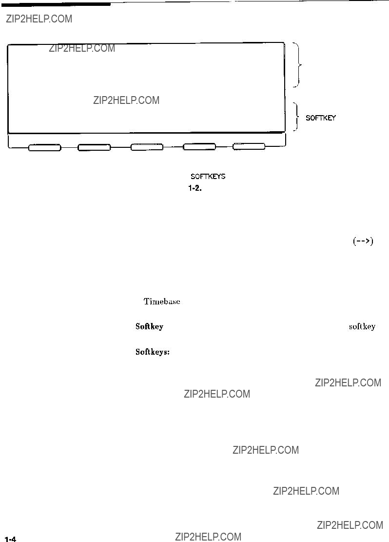
Display Area
IA C T I V E E N T R Y A N D
DATA DISPLAY AREA
- M E S S A G E L I N E
I SOFTKEY L A B E L A R E A
\
SOFTKEYS
Figure l-2. Display
Active Entry and Data Display Area: This area typically displays the frequency and power information of the current instrument state. When data entry is expected, the synthesizer uses all or part of this area to record the entries. The active entry arrow (-->) indicates the active entry function and its current value.
Message Line: This line is used to display:
ALC level status.
Unlock information.
Timebase status.
RF output status.
Softkey Label Area: This area displays the name of the softkey directly below it.
Softkeys: These keys activate the functions indicated by the labels directly above them.
l-4 Getting Started Basic

All function values are changed via the rotary knob and/or keys of the entry area.
\\, ENTRY
/ ROTARY KNOB
TERMINATOR
KMS
NUMERICNEGATlVE SIGN/
ENTRY KEYSBACKSPACE
Figure l-3. Entry Area
The following are active only when the synthesizer expects an input.
(E N T R Y O N /O F F ): This key lets you turn off or on the active entry area. Turning off the entry area after a value is entered prevents accidental changes.
ENTRY ON LED: This LED lights when the entry area is active.
Arrow Keys: The up/down arrow keys let you increase or decrease a numeric value. The left/right arrow keys choose a significant digit indicated by an underline.
Rotary Knob: The rotary knob increases or decreases a numeric value. The rotary knob can be used in combination with the left/right arrow keys to change the increment size.
Terminator Keys: After the numeric entry keys are used to enter a value, these keys define the units.
Negative Sign/Backspace Key: If a data entry is in progress, this key backspaces over the last digit entered, otherwise a negative sign is entered.
Numeric Entry Keys: These keys enter specific numbers in the active entry area and must be followed by one of the terminator keys before the function value changes.
Getting Started Basic l-5

CW Operation and
Start/Stop
Frequency Sweep
CW Operation
Start/Stop Frequency
Sweep
CW operation is one of the major functions of the synthesizer, and is easy to do using front panel keys. In CW operation, the synthesizer produces a single, low-noise, synthesized frequency. Try this example: Press(CW)(iJ@(J@@@@(7J@IGHz).
Check the active entry area. It indicates:
--> cw: 1 2 3 4 5 . 6 7 8 0 0 0 M H z
The data display area indicates CW operation and the frequency
that you entered. The ENTRY ON LED is lit and the green SWEEP LED is off.
Try other frequencies. Experiment with the rotary knob and the arrow keys as alternate methods of data entry.
The synthesizer can sweep a frequency span as wide as the frequency range of the instrument, or as narrow as 0 Hz (swept CW).
In start/stop sweep operation, the synthesizer produces a sweep from the selected start frequency to the selected stop frequency.
For example:
Press [START) @ 0 @ @ IGHz).
Press ISTOP) (7J (J (7J @ (GHz.
The data display area indicates the start frequency and the stop frequency. The green SWEEP LED is on (periodically off when sweep is retracing). Because this is the active function, the active entry area indicates:
--> STOP FREQUENCY: 7890 . 000000 MHz
Any subsequent entries change the stop frequency. To change the start frequency, press (START), which remains the active function until you press a different function key.
1-6 Getting Started Basic
Getting Started Basic 1-7

Center
Frequency/Span
Operation
Center frequency/span is another way of establishing swept
operation. This is just a different way of defining sweep limits. As an example of center frequency/span operation:
Press m(7J IGHz).
Press ISPAN) (iJ (GHz).
The synthesizer is now sweeping from 3.5 to 4.5 GHz (to view these figures, press either (START) or (STOP), then m). The data display area indicates the center frequency, as well as, the span. Notice that the green SWEEP LED is on.
While span is the active function, try the rotary knob and arrow keys. This symmetrical increase or decrease of the frequency span about the center frequency is one reason that center frequency/span swept operation is used instead of start/stop frequency sweep.
Another example illustrates the subtleties of center frequency/span.
Press (?ZFiK) @ LGHz)
Press 1SPAjj) @ (GHz)
Notice that the center frequency changed. This is because the center frequency could not accommodate a span of 8 GHz without exceeding the lower frequency limit of the synthesizer???s specified frequency range. If the low or high frequency range limits are exceeded, the inactive (center or span) function is reset. Experiment with the rotary knob and the arrow keys as alternate methods of data entry.
1-6 Getting Started Basic
Getting Started Basic l-9
Power Level and
Sweep Time
Operation
Power Level Operation
The synthesizer can produce leveled power for CW, swept frequency, or power sweep operation. The selected power level can range from -20 dBm (-110 dBm for option 001 synthesizers) to +25 dBm.
For practice: Press (POWER LEVEL) I-] @ @ (dB(mL). The active entry area shows:
--> POWER LEVEL: -20.00 dBm
If the selected power level is beyond the range of the synthesizer, the closest possible power is shown in both the data display area and the active entry area. If the selected power level exceeds the maximum leveled power the synthesizer is able to produce, the unleveled message UNLVLED appears on the message line. Experiment with the rotary knob and the arrow keys as alternate methods of data entry.
Sweep Time Operation In typical applications the sweep time can vary tremendously, from milliseconds in a network analyzer system, to more than a minute in
thermistor-based power meter systems. For this example, refer to the ???MENU MAP??? section.
Press @%Ki) @ [GHz).
Press ISTOP) @ (GHz).
Press lsWEEP @ 0 (ZJ (,,,).
Watch the green SWEEP LED, it blinks every 2.5 seconds. The LED blinks at each retrace.
For the fastest sweep speed for which all specifications are guaranteed, the synthesizer must be in automatic sweep time selection.
Refer to menu map 8.
Press SWEEP [MENU).
Select more if3 .
Select SwpTime Aut0 .
Notice that the active entry area indicates:
When the synthesizer is in automatic sweep time selection, the active entry area displays AUTO along with the current sweep time. Faster sweep speeds than this are possible, turn the rotary knob counter-clockwise until the display no longer changes. Notice that AUTO is no longer displayed
l-10 Getting Started Basic
. .,WLETT L???pI PACKARO
/
Getting Started Basic l-l 1

Continuous, Single,
and Manual Sweep
Operation
Continuous sweep is the operation mode set when the synthesizer is preset. It simply means that when the synthesizer is performing a swept operation, the sweeps will continuously sweep-retrace-sweep- retrace until a different sweep mode is selected. To choose this sweep mode, press (CONT).
To change from continuous sweep to single sweep operation, press ($?@. This causes the synthesizer to abort the sweep in progress and switch to the single sweep mode. This initial keystroke cause???s the synthesizer to switch sweep modes, but it does not initiate a single sweep. A second keystroke (press (%jGFJ initiates a single sweep. When the synthesizer is in single sweep operation, the amber LED above the key lights. When the synthesizer is actually performing a sweep in single sweep mode, the green SWEEP LED lights.
The manual sweep mode lets you use the rotary knob to either sweep from the start frequency to the stop frequency or to sweep power.
Refer to menu map 8, SYSTEM.
Press (PRESET).
Press SWEEP (j).
Select Manual Beep.
The active entry area displays:
--> SWEPT MANUAL: XXXXXXXXX MHz
Use the rotary knob to sweep from the start to the stop frequency. The green SWEEP LED is off in manual sweep mode because the sweeps are synthesized.
1-12 Getting Started Basic
Getting Started Basic 1-13

The synthesizer has five frequency markers that can be used as fixed frequency ???landmarks,??? or as variable frequency pointers on a CRT display. To view the marker features of the synthesizer on a CRT, connect the synthesizer as shown in Figure 1-8.
Refer to menu map 2, FREQUENCY.
Press [PRESET).
Press (START) @ @&).
Press (STOP) 0 [GHz).
Press [MARKER).
Select Marker Ml and enter @ (GHz.
The synthesizer is sweeping from 3 to 7 GHz, with a 100 ms sweep speed. A frequency marker is set at 4 GHz, which causes an intensified dot to appear on the CRT. To obtain an amplitude spike at that frequency, select Amp1 Markers . Notice that you can set the amplitude of the spike with the rotary knob or entry keys. To return to the intensified dot representation, select Amp1 Markers (asterisk off).
Amplitude markers increase the output power at the marker frequency. Provide protection to devices that could be damaged.
For a second marker, select Marker M2 and enter @ 0 @ (GHz).
This process can be continued for all five markers. Note that the marker displayed in the active entry area is ???active??? and can be controlled by the rotary knob, arrow keys, and numeric entry keys.
Once the Ml and M2 markers are established, the marker sweep function, softkey MI--M2 Sweep, temporarily changes the original start/stop frequencies to those of markers Ml and M2. Select Ml--M2 Sweep. Notice that the synthesizer now is sweeping from 4 to 5.5 GHz. Use this function to focus in on a selected portion of the frequency sweep. Select Ml--M2 Sweep again. This turns the function off and returns the synthesizer to its original sweep
parameters. To change the start/stop frequencies for the synthesizer, not just temporarily, use the softkey Start-Ml Stop'M2 .
As an example of the delta marker function:
Select Marker M3 and enter @ 0 0 IGHz).
Select Delta Marker.
The frequency difference between marker 3 and marker 1 is displayed, and the CRT trace is intensified between the two markers. The active entry area displays:
--> D E L T A M K R (3-l) : 2 7 0 0 . 0 0 0 0 0 0 M H z
1-14 Getting Started Basic
Marker 1 was chosen because it is selected as the delta marker reference. To change reference markers, select Delta Mkr Ref .
Select M2 as the reference. Watch the display change to indicate:
--> D E L T A M K R ( 3 - 2 ) : 1 2 0 0 . 0 0 0 0 0 0 M H z
You can choose any of the five markers as a reference, but when delta marker is on, if the reference marker has a frequency value higher than the last active marker, the difference between the frequencies
is negative and is displayed as such by the synthesizer. The CRT display continues to intensify the difference between the two markers.
When delta marker is showing in the active entry area, the ENTRY area is active. Rotate the rotary knob and watch the frequency difference change. The last active marker (in this case, marker 3) changes frequency value, not the reference marker.
OSCILLOSCoPE
1.Press @i?GGiZ).
2.Select a marker key ( Ni . . MS ).
3.Enter value.
4.Press terminator key.
1.Press @ZiGiF].
2.Select a marker key ( #I . . NE ).
3.Enter value.
4.Press terminator key.
5.Select a different marker key (Ml . . . MS).
6.Enter value.
7.Press terminator key.
8.Select Delta l4kr Ref .
9.Select one of the previously chosen markers.
10.Press (jZi?%J
11 . Select Delta M a r k e r
Getting Started Basic 1-15
Saving and
Recalling an
Instrument State
The save/recall registers store and access a previously set instrument state. For example, set the synthesizer to sweep from 3 to 15 GHz at a -10 dB power level, with markers 1 and 2 set at 4.5 and 11.2 GHz.
Press [START) (7J (GHz).
Press (STOP) (7J (?J (GHz.
P r e s s ( P O W E R LEVEL] I - ] (iJ (TJ 0).
Press (MARKER).
Select Marker Ml @ 0 @ IGHz).
Select Marker M2 0 0 0 @ (GHzl.
To save this instrument state in register 1, press (SAVE) (iJ. To verify that the synthesizer has saved this state:
Press (PRESET).
Press (RECALL) (iJ.
Press [MARKER).
The active entry area displays:
--> RECALL REGISTER: 1 RECALLED
Notice the sweep end points, power level, and the asterisks next to the marker 1 and 2 key labels.
You can save instrument states in registers 1 through 8. Register 0 saves the last instrument state before power is turned off. When power is turned on, register 0 is automatically recalled.
1-16 Getting Started Basic
RECALL
Figure 1-9. Saving and Recalling an Instrument State
Getting Started Basic l-17

Power Sweep and
Power Slope
Operation
Power Sweep Operation
The power sweep function allows the power output to be swept (positive or negative) when the synthesizer is in the CW frequency mode. The power output of the synthesizer determines the maximum leveled power sweep that can be accomplished. For this example refer to the ???Menu Map??? section.
Zero and calibrate the power meter.
Connect the instruments as shown in Figure l-10.
Press @ @ [GHz).
Press ( P O W E R LEVEL) (TJ (YiJ.
Press (SWEEP @ (,,,) [SINGLE).
Set the power meter to dB[REF] mode.
The synthesizer is ready to produce a 4 GHz CW signal at 0 dBm power out, with a 2 second sweep rate whenever a single sweep is executed. The power meter is ready to measure the power level relative to a starting point of 0 dBm.
Press POWER (MENU).
Select Power Sweep and enter @ (dB0) (asterisk on).
Press [$iKKJ.
Watch the relative power indication on the power meter. At the end of the sweep the power meter indicates +7 dB. The active entry area on the synthesizer indicates:
--> POWER SWEEP: 7 . 00 dB/SWP
Now enter @ @ (dB(m)) (power sweep is still the active entry function).
This time the power meter indicates less than the power sweep requested. Note that the synthesizer is unleveled, UNLVD. This happens because the synthesizer???s output power at the start of the sweep is 0 dB and the requested power sweep takes the synthesizer beyond the range where it is able to produce leveled power. The range of the power sweep is dependent on the ALC range and can be offset if a step attenuator (Option 001) is present.
Select Power Sweep to turn this function off (no asterisk).
Press [POWER LEVEL) !_) Q (FJ
On the power meter, press dB[REF] to reset the reference level.
1-18 Getting Started Basic
Select Power Sweep (asterisk on).
Press (SINGLE].
The synthesizer performs a power sweep beginning at -20 dBm and ending at f5 dBm. The power meter indicates +25 dB.
Power Slope Operation This function allows for compensation of high frequency system or cable losses by linearly increasing the power output as the frequency
increases. For this example refer to the ???Menu Map??? section.
Press Power Slope , the active entry area displays:
--> RF SLOPE: X. XX dB/GHz, where X is a numeric value.
Power slope is now active, notice that an asterisk is next to the key label.
Use the entry keys, rotary knob, or arrow keys to enter a value for the linear slope.
Press Power Slope again to turn this feature off.
Getting Started Basic l-19
???UT
Figure l-10. Power Sweep and Power Slope Operation
1. Press POWER (jMENU).
2.Select Pouer Saeep .
3.Enter a value.
4.Press terminator key.
1. Press POWER (jj).
2 . S e l e c t Power S l o p e
3.Enter a value.
4.Press terminator key.
l-20 Getting Started Basic
This section of Chapter 1 describes the use of many of the unique features of the HP 8360 Series Synthesized Sweepers. The format used is similar to the one used on the previous pages. When referred to a menu map number, go to the Menu Map tab and unfold the menu map so that you can view it together with the text.
Some menus have more than one page of softkeys. Select the more m/n softkey to view the next page of softkeys. more m/n is not included in the keystrokes given in these procedures.
Table l-l. Keys Under Discussion in This Section
Getting Started Advanced 1-21
Advanced
Table l-l.
Keys Under Discussion in This Section (continued)
For more information,each of these keys has a separate entry in the
???OPERATING and PROGRAMMING REFERENCE??? chapter of this handbook.
1-22 Getting Started Advanced
Externally Leveling
the Synthesizer
In externally leveled operations, the output power from the synthesizer is detected by an external sensor. The output of this detector is returned to the leveling circuitry, and the output power is automatically adjusted to keep power constant at the point of detection.
Leveling with Detectors/Couplers /Splitters
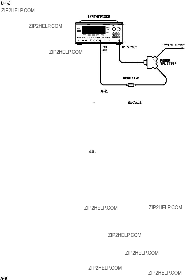
Figure l-11 illustrates a typical setup for external leveling. When externally leveled, the power level feedback is taken from the external negative detector input rather than the internal detector. This feedback voltage controls the ALC system to set the desired RF output. Refer to Figure A-l in Chapter 2, for a block diagram of the synthesizer???s ALC circuitry.
SYNTHESIZER
NEGATIVE
LEVELED OUTPUT
b
Figure l-1 1. ALC Circuit Externally Leveled
Getting Started Advanced 1-23
To level externally:
1.Setup the equipment as shown. For this example, the detector/coupler setup is used.
2.Refer to menu map 1.
3.Press (ALC).
4.Select Leveling Point ExtDet .
5.Set the coupling factor. Select Coupling Factor c-) @ @ (dB(m)).
l-24 Getting Started Advanced
100 mV iii SQUARE LAW ASYMPTOTE
10 mV
1 mV
+20 d6V
+lO dBV
0dBV
-1 0 dBV
-2 0 dBV
-3 0 dBV
-4 0 dBV
-5 0 dBV
-60 dBV
.-66 dBV
- 7 0 dBV
DETECTOR INPUT POWER, dBm
Figure 1-12. Typical Diode Detector Response at 25??C
Getting Started Advanced l-25

External Leveling Used With the Optional Step Attenuator
Some external leveling applications require low output power
from the synthesizer. The synthesizer automatically uncouples the attenuator from the ALC system for all external leveling points.
Press ( P O W E R L E V E L ) . Note the display. It shows:
--> ATTEN 0 dB, POWER LEVEL: 0.00 dBm
For example, leveling the output of a 30 dB gain amplifier to a level of -10 dBm requires the output of the synthesizer to be around
-40 dBm when leveled. At some frequencies this level is beyond the range of the ALC modulator alone. If so, the LOW UNLVLED warning message is displayed. Inserting 40 dB of attenuation results in an ALC level of 0 dBm, which is well within the range of the ALC. At 20 GHz,30 dB attenuation is a better choice as it results in an ALC level of -10 dBm. This gives a margin for AM or other functions that vary the power level.
For optimum display accuracy and minimum noise, the ALC level should be greater than -10 dBm. This is achieved by using attenuation equal to the tens digit of output power. Example: desired output power = -43 dBm; use:
--> ATTEN: 40 dB , ALC -3 dBm
1.Press POWER (MENU).
2.Select Set Atten @ @ 0).
Hint To obtain flatness corrected power refer to ???Optimizing Synthesizer Performance, Creating and Applying the User Flatness Correction Array,??? later in this section.
l-26 Getting Started Advanced
Leveling with Power Meters
Leveling with a power meter is similar to leveling with a diode detector. Figure 1-13 shows the setup for power meter leveling.
SYNTHESIZER
POUER
HETER
Figure 1-13. Leveling with a Power Meter
1.Set up the equipment as shown. Be sure to set the power meter to manual range mode and note the range.
2.Refer to menu map 1.
3.Press a).
4.Select Leveling Point PwrHts .
5.Select Pwr Mtr Range. Enter the range value set for the power meter as noted in step 1.
6.Select Coupling Factor , press @???J (de(m)).
Unlike detector leveling, power meter leveling provides calibrated power out of the leveled RF port.
Getting Started Advanced l-27
Leveling with MM-wave Source Modules
Millimeter-wave source module leveling is similar to power meter leveling. The following figures illustrate the setups for leveling with a mm-wave source module.
SYNTHESIZER
Figure 1-14. MM-wave Source Module Leveling
High power model synthesizers can externally, level mm-wave source modules to maximum specified power without a microwave amplifier.
1-28 Getting Started Advanced
RF OUT
RF OUT I???ll-LINE SOURCE
NODULE
Figure 1-15. MM-wave Source Module Leveling Using a Microwave Amplifier
1.Set up the equipment as shown.
2.Refer to menu map 1.
3.Select Leveling Point Module.
4.Select Mdl Lev Menu.
5.Select Module Leveling Pt Auto or Front or Rear, depending on where the interface connection is made.
All of the ALC data necessary to communicate properly with the synthesizer is exchanged via the SOURCE MODULE INTERFACE.
Getting Started Advanced 1-29

Working with Mixers/Reverse Power Effects
Note
Uncoupled operation applies to Option 001 synthesizers only.
Uncoupled operation is useful when working with mixers. Figure 1-16 shows a hypothetical setup where the synthesizer is providing
a small signal to a mixer. The synthesizer output is -8 dBm, which in Leveling Node Normal results in ATTEN = 0 dB,
ALC Level = -8 dBm. The mixer is driven with an LO of +lO dBm, and has LO to RF isolation of 15 dB. The resulting LO feedthrough of -5 dBm enters the synthesizer???s OUTPUT port, goes through
the attenuator with no loss, and arrives at the internal detector. Depending on frequency, it is possible for most of this energy to enter the detector. Since the detector responds to its total input power regardless of frequency, this excess energy causes the leveling circuit to reduce its output. In this example the reverse power is actually larger than the ALC level, which may result in the synthesizer output being shut off.
1.Press POWER (MENU).
2.Select Set Atten and press (iJ @J (dB(m)). This step does two things, it uncouples the attenuator from the rest of the ALC system, and it lets you set an attenuator value, in this case, 10 dB.
3.Press [POWER LEVEL) (?J (j-l). This sets the ALC level to +2 dBm.
For more information on the ALC or setting power level, refer to IALC) or (POWER LEVEL) in Chapter 2.
I-30 Getting Started Advanced
Figure l-16. Reverse Power Effects, Coupled Operation with -6dBm Output
Figure 1-17. Reverse Power Effects, Uncoupled Operation with -6dBm Output
Getting Started Advanced l-31

Working with Spectrum Analyzers/Reverse Power Effects
Reverse power is a problem with spectrum analyzers that do not have preselection capability. Some analyzers have as much as +5 dBm LO feedthrough coming out of their RF input, at some
frequencies. The effects of reverse power are less in the heterodyne band (0.01 to 2.3 GHz) where the power amplifier provides some broadband matching. Similarly, at frequencies above 2.3 GHz, reverse power that is within 10 MHz of the synthesizer???s frequency may be partially absorbed by the YIG filter. If the frequency difference is small enough to be within the leveling system bandwidth (typically 10 kHz CW, 200 kHz sweep or AM), the effect of reverse power is amplitude modulation of the synthesizer???s output. The AM rate equals the difference in RF frequencies. Reverse power problems may be treated by using the unleveled mode. There are two unleveled modes, ALC off and search.
To set the synthesizer to the ALC off mode:
1.Refer to menu map 1.
2.Press (ALC).
3.Select Leveling Mode ALCoff .
In this mode, the synthesizer provides RF power with no ALC correction and therefore requires a power meter to set a particular power.
To set the synthesizer to the search mode:
1.Press (ALC.
2.Select Leveling Mode Search.
In this mode, the synthesizer is in the normal ALC mode until the desired power level is reached, then the ALC is disconnected.
1-32 Getting Started Advanced

Optimizing
Synthesizer
Performance
Creating and Applying
the User Flatness
Correction Array
The following examples demonstrate the user flatness correction feature:
1.Using an HP 437B power meter to automatically enter correction data for a swept 4 to 10 GHz measurement.
2.Manually entering correction data for a stepped (List Mode) measurement.
3.Making swept mm-wave measurements, automatically entering correction data for an arbitrary list of correction frequencies.
4.Making scalar analysis measurements with automatically-entered correction data that compensates for power variations at the output of a directional bridge.
Each example illustrates how to set up correction tables for a different measurement requirement. Modify the instrument setups shown to suit your particular needs. Completed correction tables may be easily edited if more correction data is required for your measurement. Additional correction frequencies may be added
by using the auto fill feature or by entering correction frequencies individually. The auto fill feature adds but does not delete correction frequencies.
There are two basic front-panel methods of creating a flatness correction array. The first and quickest method is to use an HP 437B power meter. Refer to Figure 1-18 for the setup. The second method is just as accurate, but requires a little more interaction between the operator and the instruments. Figure 1-19 shows the setup for the second method.
Getting Started Advanced 1-33

Creating a User Flatness Array Automatically, Example 1
In this example, a flatness array containing correction frequencies from 4 to 10 GHz at 1 GHz intervals is created. An HP 438B power meter controlled by the synthesizer through the interface bus is used to enter the correction data into the flatness array.
For this example, refer to menu map 5, POWER.
1. The equipment setup shown in Figure 1-18 assumes that if the setup has an external leveling configuration, the steps necessary to correctly level have been followed. If you have questions about external leveling refer to earlier paragraphs titled, ???Externally Leveling the Synthesizer.???
Setup Power Meter
2.Zero and calibrate the power meter/sensor.
3.Enter the appropriate power sensor calibration factors into the power meter.
4.Enable the power meter/sensor cal factor array. For operating information on the HP 437B power refer to its operating and service manual.
5.Connect the power sensor to the point where corrected power is desired.
I COmxTEo
, OUTFIJT PORT
M
HP $778
POYER NE TER
POUER SENSOR
------B-B- - - - - -
Figure 1-16. Creating a User Flatness Array Automatically
1-34 Getting Started Advanced

Setup Synthesizer Parameters
6.On the synthesizer, press (PRESET).
7.FREQUENCY ISTART) @ LGHz), LSTOP) 0 @ LGHz).
8.(POWER LEVEL) (TJ m.
Access User Flatness Correction Menu
9.Press POWER [MENU). Select Fitness Menu.
10.Select Delete Menu Delete All . This step insures that the flatness array is empty.
11.Press (6%). Leave the delete menu and return to the previous soft key menu.
12Enter the frequency points at which the correction information will be taken. Choose either the point-by-point entry method Enter Freq or the automatic frequency point generation
Auto Fill Start. For this example,select Auto Fill Start
@IGHz).
13Select Auto Fill Stop a@=, Auto Fill Incr a[GHz).
Notice that a frequency list starting at 4 and ending at 10 GHz with an increment value of 1 GHz is created.
Enter Correction Data into Array
14.Select Mtr Meas Menu Measure Cars All. The power meter is now under synthesizer control and is performing the sequence of steps necessary to generate the correction information at each frequency point.
If an HP-IB error message is displayed verify that the interface connections are correct. Check the HP-IB address of the power meter and ensure that it is the same address the synthesizer is using (address 13 is assumed). Refer to the menu map 8, System, for the key sequence necessary to reach softkey Meter Adrs .
Enable User Flatness Correction
15.When the operation is complete, (a message is displayed) the flatness correction array is ready to be applied to your setup. Disconnect the power meter/sensor and press [FLTNESS ON/OFF) (amber LED on). The power produced at the point where the power meter/sensor was disconnected is now calibrated at the frequencies and power level specified above.
Getting Started Advanced l-35

Creating a User Flatness Array, Example 2
This example shows how to use the synthesizer and a power meter in manual entry mode. This example also introduces two features of the synthesizer. The softkey Freq Follow simplifies the data entry
process and the softkey List Mode sets up a list of arbitrary test frequencies.
The frequency follow feature automatically sets the source to a CW test frequency equivalent to the active correction frequency in the user flatness correction table. The front panel arrow keys are used to move around the correction table and enter frequency-correction pairs. Simultaneously, the synthesizer test frequency is updated to the selected correction frequency without exiting the correction table.
To further simplify the data entry process, the synthesizer allows you to enter correction data into the user flatness correction table by adjusting the front panel knob until the desired power level is displayed on the power meter. The user flatness correction algorithm automatically calculates the appropriate correction and enters it into the table. If you already have a table of correction data prepared, it can be entered directly into the correction table using the front-panel keypad of the synthesizer.
With the list mode feature, you may enter the test frequencies into a table in any order and specify an offset (power) and/or a dwell time for each frequency. When list mode is enabled, the synthesizer steps through the list of frequencies in the order entered.
The user flatness correction feature has the capability of copying and entering the frequency list into the correction table. Since the offset in the list mode table is not active during the user flatness correction data entry process, the value of the correction data is determined as if no offset is entered. When user flatness correction and list mode (with offsets) are enabled, the synthesizer adjusts the output power by an amount equivalent to the sum of the correction data and offset for each test frequency. You must make sure that the resulting power level is still within the ALC range of the synthesizer.
1-36 Getting Started Advanced
Figure 1-19. Creating a User Flatness Array
For this example, refer to menu map 5, POWER.
1.The equipment setup shown in Figure 1-19 assumes that if your setup has an external leveling configuration, the steps necessary to correctly level have been followed. If you have questions about external leveling refer to earlier paragraphs titled, ???Externally Leveling the Synthesizer .???
Setup Power Meter
2.Zero and calibrate the power meter/sensor.
3.Connect the power sensor to the point where flatness corrected power is desired.
Setup Synthesizer Parameters
4. On the synthesizer, press (PRESET).
5.( P O W E R L E V E L ) @ 0). This sets the test port power to +5
dBm (PO max - Ppath loss).
Create A Frequency List
On the synthesizer, press FREQUENCY (E).
Select List Menu Enter List Freq @ (GHz). This enters 5 GHz as the first frequency in the list array. Entering a frequency automatically sets the offset to 0 dB and the dwell to 10 ms.
Enter 18, 13, 11, and 20 GHz to complete this example array.
Getting Started Advanced 1-37

Access User Flatness Correction Menu
9.Press POWER (z). Select Fitness Menu.
10.Select Delete Menu Delete All. This step insures that the flatness array is empty.
11.Press (=I. Leave the delete menu and return to the previous soft key menu.
12.Select Copy List This step copies the frequency list into the correction table in sequential order.
13.Select Freq Follow. This sets the synthesizer to CW frequency mode to facilitate taking correction information. As you scroll through the correction cells, the synthesizer produces the corresponding CW frequency at 0 dBm.
14.Select Enter Corr . This allows correction value entry.
15.Press (FLTNESS ON/OFF). This step enables user flatness correction.
16.For 5 GHz, set the appropriate power sensor cal factor on the power meter.
17.Use the synthesizer rotary knob to adjust for a measurement of
0.00dBm on the power meter. Notice that a correction value is entered at 5 GHz.
18.Use the up arrow key to increment to the next correction cell.
19.For 11 GHz, set the appropriate power sensor cal factor on the power meter.
20.Use the synthesizer rotary knob to adjust for a measurement of
0.00dBm on the power meter.
21.Repeat this sequence of steps until all the frequency points have a correction value entered.
Activate List Mode
22.Press SWEEP (MENU]. Select Sweep Mode List .
23.The flatness correction array is ready to be applied to your setup. Disconnect the power meter/sensor. The power produced at the point where the power meter/sensor was disconnected is now calibrated at the frequencies and power level specified above.
l-38 Getting Started Advanced
Getting Started Advanced 1-39
HICROURVE RNPLIFIER
Figure l-20.
Creating Arbitrarily Spaced Frequency-Correction Pairs in a Swept mm-wave Environment
For this example, refer to menu map 5, POWER.
1.The equipment setup shown in Figure l-20 assumes that you have followed the steps necessary to correctly level the configuration. If you have questions about external leveling refer to earlier paragraphs titled, ???Externally Leveling the Synthesizer.???
Setup Power Meter
2.Zero and calibrate the power meter/sensor.
3.Connect the power sensor to test port.
4.Enter and store in the power meter, the power sensor???s cal factors for correction frequencies to be used.
l-40 Getting Started Advanced
Setup Synthesizer Parameters
5.Turn on the synthesizer and press [PRESET). The following occurs:
nThe source module???s frequency span is displayed on the synthesizer.
nThe synthesizer???s leveling mode is automatically changed from internal to ???module leveling???.
nThe source module???s maximum specified power is set and displayed.
6.Press FREQUENCY (START) @ @ 0 @ (GHz, m@ @ IGHz). The frequency sweep is set from 26.5 to 40 GHz.
7.Press (POWER LEVEL) 0 @. The source module power is set to +7 dBm for maximum power to the device under test.
Access User Flatness Correction Menu
8.Press POWER CE). Select Fltness Menu.
9.Select Delete Menu Delete All. This step insures that the flatness array is empty.
10.Press (PRIOR). Leave the delete menu and return to the previous softkey menu.
11.Select Enter Freq (!?J @ 0 @ (GHz), to enter 26.5 GHz as the first correction frequency. Enter 31, 32.5, and 40 GHz to complete the list. Notice that the frequencies are arbitrarily spaced.
Enter Correction Data into Array
12.Select Mtr Meas Menu Measure Corr All. The power meter
is now under synthesizer control and is performing the sequence of steps necessary to generate the correction information at each frequency point.
If an HP-IB error message is displayed verify that the interface connections are correct. Check the HP-IB address of the power meter and ensure that it is the same address the synthesizer is
Getting Started Advanced 1-41
using (address 13 is assumed). Refer to the menu map 8, System, for the key sequence necessary to reach softkey Meter Adrs .
Enable User Flatness Correction
13.When the operation is complete, (a message is displayed) the flatness correction array is ready to be applied to your setup.
14.To save the synthesizer parameters including the correction table in an internal register, press ISAVE) 0.
(n = number 1 through 8).
15.Disconnect the power meter/sensor and press (FLTNESS ON/OFF) [amber LED on). The power produced at the point where the power meter/sensor was disconnected is now calibrated at the frequencies and power level specified above.
l-42 Getting Started Advanced
Scalar Analysis Measurement with User Flatness Corrections,
Example 4
The following example demonstrates how to setup a scalar analysis measurement (using an HP 8757 Scalar Network Analyzer) of a 2 to 20 GHz test device such as, an amplifier. User flatness correction
is used to compensate for power variations at the test port of a directional bridge. Follow the instructions to set up the synthesizer, then configure the system as shown in Figure 1-21.
DETECTOR
OIRECTIONRL
DETECTOR I
Figure l-2 1. Scalar System Configuration
Example Overview
In this example you use an HP 437B power meter to automatically enter correction data into the array. It is necessary to turn off
the HP 8757 System Interface (controlled from the front-panel of the analyzer) so that the synthesizer can temporarily control the power meter over HP-IB . When the correction data entry process is complete, enable user flatness correction and set the desired test port power level. Then store the correction table and synthesizer configuration in the same register that contains the analyzer configuration. Re-activate the HP 8757 System Interface and recall
Getting Started Advanced 1-43

the stored register. Make sure that user flatness correction is still enabled before making the measurement.
When an HP 437B power meter is used to automatically enter the correction data, the correction calibration routine automatically turns off any active modulation, then re-activates the modulation upon
the completion of the data entry process. Therefore, the scalar pulse modulation that is automatically enabled in a scalar measurement system is disabled during an HP 437B correction calibration.
For this example, refer to menu map 5, POWER.
1.The equipment setup shown in Figure 1-21 assumes that you have followed the steps necessary to correctly level the configuration. If you have questions about external leveling refer to earlier paragraphs titled, ???Externally Leveling the Synthesizer .???
2.On the analyzer, press [PRESET). Reset the analyzer and synthesizer to a known state.
Setup System Parameters
3.On the synthesizer, press FREQUENCY (START) @ (GHz, (STOP)@@m.S et the s nythesizer for a frequency sweep of 2 to 20 GHz.
4.Press [POWER LEVEL) 0 @. Where n = maximum available power.
5.On the analyzer, set up the appropriate measurement
(i.e. gain for an amplifier). Calibrate the measurement (thru and short/open calibration). Press ISAVE) (iJ to store the analyzer???s configuration and synthesizer parameters in storage register 1.
6.Turn off the HP 8757 System Interface. Use the analyzer
SYSINTF ON OFF softkey found under the SYSTEM menu to deactivate the system interface.
Access User Flatness Correction Menu
7.On the synthesizer, press POWER Cm). Select Fltnesa M e n u .
8.Select Delete Menu Delete All . This step insures that the flatness array is empty.
1-44 Getting Started Advanced

9.Press (PRIOR). Leave the delete menu and return to the previous soft key menu.
10. Select Auto Fill Start @ m). Set the first frequency in correction table to 2 GHz.
11.Auto Fill Stop @ @J (GHz). Set the last frequency in correction table to 20 GHz.
12.Auto Fill Incr 0 @ @ INIHz). Set the frequency increment to every 100 MHz from 2 to 20 GHz.
Setup Power Meter
13.Zero and calibrate the power meter/sensor.
14.Connect the power sensor to test port.
15.Enter and store in the power meter, the power sensor???s cal factors for correction frequencies to be used.
Enter Correction Data into Array
16.Select Mtr Meas Menu Measure Corr All . The power meter
is now under synthesizer control and is performing the sequence of steps necessary to generate the correction information at each frequency point.
If an HP-IB error message is displayed verify that the interface connections are correct. Check the HP-IB address of the power meter and ensure that it is the same address the synthesizer is using (address 13 is assumed). Refer to the menu map 8, System, for the key sequence necessary to reach softkey Meter Adrs .
Enable User Flatness Correction
17.When the operation is complete, (a message is displayed) the flatness correction array is ready to be applied to your setup.
18.Disconnect the power meter/sensor.
19.On the synthesizer, press [POWER LEVEL) 0 (dBm). Where
n = PO max - Ppath l o s s for maximum leveled power at the test port.
20.To save the synthesizer parameters including the correction table in an internal register, press ISAVE) (XJ.
(n = number 1 through 8).
Reactivate the HP 8757 System Interface
21.Set the analyzer to SYSINTF ON, the analyzer and synthesizer preset.
22.Press (RECALL) 0, Recall the synthesizer parameters from storage register 1
Getting Started Advanced l-45
23.On the synthesizer, press [FLTNESS ON/OFF) (amber LED on). The power produced at the point where the power meter/sensor was disconnected is now calibrated at the frequencies and power level specified above.
1-46 Getting Started Advanced
Using Detector
Calibration
Detector calibration is useful for characterizing and compensating for negative diode detectors used in external leveling. Detectors may be characterized by three operating regions as shown in Figure 1-12:
the square law, the linear, and the transition region. The following steps use an HP 437B to automatically characterize the operating regions and use this information to automatically compensate for the detector being used. The equipment setup shown in Figure l-22 assumes that .the steps necessary to correctly externally level have been followed.
Refer to menu map 9, USER CAL.
HP $378
POUER NETER
Figure l-22. Automatically Characterizing and Compensating for a Detector
1.Connect the power meter as shown.
2.Zero and calibrate the power meter/sensor.
3.Enter the appropriate power sensor calibration factors into the power meter.
4.Enable the power meter/sensor cal factor array. For operating information on the
HP 437B power meter refer to its operating and service manual.
5.Connect the power sensor to the output of the coupler (or splitter).
6.On the synthesizer, set the power level and start/stop frequency information as desired.
7.Press [USERCAL).
8.Select Ext Det Gal . The power meter is now under synthesizer control and is performing the sequence of steps necessary to generate the compensation information.
Getting Started Advanced 1-47
If an HP-IB error message is displayed verify that the interface connections are correct. Check the HP-IB address of the power meter and ensure that it is the same address the synthesizer is using (address 13 is assumed). Refer to the menu map 8, System, for the key sequence necessary to reach softkey Meter A&s .
9.When the operation is complete, (a message is displayed) disconnect the power meter/sensor. The synthesizer has stored the compensation information in its memory and is using it to calibrate the detector???s output voltage relative to power.
1-48 Getting Started Advanced
Using the Tracking
Feature
Peaking
Peaking is the function that aligns the output filter (YTM) so that its passband is centered on the RF output, in CW or manual-sweep mode. Use peaking to obtain the maximum available power and spectral purity, and best pulse envelopes, at any given frequency above 2.35 GHz (or 2 GHz, when 2 GHz is the minimum frequency specified). The YTM is inactive for the low band frequencies
(10 MHz to 2.35 GHz).
To peak at the present CW frequency:
Press ( U S E R ) .
Select Tracking Menu Peak RF Once.
This causes an instantaneous execution of the peaking function. This is a one-time implementation of the peaking, where the function is turned on and then turned off.
To peak at the present CW frequency, and continue to peak at new frequencies as they are entered:
Press ( U S E R ) .
Select Tracking Menu Peak RF Always.
If ???peak always??? is on (denoted by an asterisk next to the key label) for an extended period of time, the peaking function will automatically repeak every seven minutes.
Getting Started Advanced 1-49
The ALC bandwidth defaults at factory preset to the auto selection ALC Bandwidth Select Auto which selects the appropriate bandwidth (high or low) for each application. To make the bandwidth selection, the synthesizer determines which functions are activated and uses the decision tree shown in Figure l-23.
1N O
M( on? I - o r -
SEh?
- o r -
List
FlVCp.lK#
Low??? SW- o r -
SOP swamp7
NO
T
Low Bw
Figure l-23. Decision Tree for ALC Bandwidth Selection
l-50 Getting Started Advanced
1.Refer to menu map 2.
2.Press FREQUENCY [e].
3.Select Step Swp Menu.
4.Select Step Size. Enter the desired increment value.
5.Select Step Points. Enter the number of points desired.
6.Determine the dwell time desired, select Step Dwell and enter a value, or choose the dwell time determined by the ramp mode sweep time, select ISwe Coupled .
7.Determine the triggering scheme, select Step Swp Pt Trig Auto ,
Bus, or Ext
8.Press SWEEP (MENU).
9.Select Sweep Mode Step, to activate the step frequency mode.
Getting Started Advanced l-5 1
Creating and Using
a Frequency List
1.Refer to menu map 2.
2.Press FREQUENCY (hnENU).
3.Select List Menu.
To use the frequency points of a frequency list to create the frequency portion of the user flatness correction array:
1.Refer to menu map 5.
2.Press POWER (???MENU).
3.Select Fltnesa Menu.
4.Select Copy List .
1-52 Getting Started Advanced
Using the Security
Features
To access the security menu:
1.Refer to menu map 8.
2.Press SYSTEM @K).
3.S e l e c t S e c u r i t y M e n u .
Getting Started Advanced l-53
Changing the Preset
Parameters
1.Setup the synthesizer in the desired operation state to be used as the preset state.
2.Refer to menu map 8.
3.Press SYSTEM (e).
4.Select Save User Preset.
5.Select Preset Mode User.
Whenever the (PRESET) key is pressed, the synthesizer will return to the operation state setup and saved in steps 1 and 4. The synthesizer displays:
*** USER DEFINED PRESET RECALLED ***
and also gives you the option of selecting the factory preset state by creating a factory preset softkey.
1-54 Getting Started Advanced
Getting Started
Programming
Programming
HP-IB, the Hewlett-Packard Interface Bus, is the instrument-to- instrument communication system between the synthesizer and up to 14 other instruments. Any instrument having HP-IB capability can be interfaced to the synthesizer, including non-HP instruments that have ???GPIB,??? ???IEEE-488,??? ??? ANSI MC1.l,??? or ???IEC-625??? capability (these are common generic terms for HP-IB; all are electrically equivalent although IEC-625 uses a unique connector). This portion of the manual specifically describes interfacing the synthesizer to one type of instrument: a computer.
The first part of this section provides general HP-IB information. Later, the Standard Commands for Programmable Instruments language (SCPI) is introduced, and example programs are given. For information on programming in the Control Interface Intermediate Language (CIIL), refer to a separate option 700 manual supplement.
Getting Started Programming l-55
HP-IB General
Information
Interconnecting Cables
Figure C-2 shows the synthesizer rear-panel HP-IB connector and suitable cables, and describes the procedures and limitations for interconnecting instruments. Cable length restrictions, also described in Figure C-2, must be observed to prevent transmission.
Instrument Addresses Each instrument in an HP-IB network must have a unique address, ranging in value from 00-30 (decimal). The default address for the synthesizer is 19, but this can be changed using the My adrrs softkey or rear panel switch as described in the reference chapter (Chapter 2) under the ???8360 Adrs??? entry (the examples in this section use 19 as the address for the synthesizer). Other instruments use a variety of procedures for setting the address, as described in their operating manuals, but typically either a rear panel switch or a front panel code is used.
HP-IB Instrument
Nomenclature
Programming the
Synthesizer
An HP-IB instrument is categorized as a ???listener,??? ???talker,??? or ???controller,??? depending on its current function in the network.
Listener
A listener is a device capable of receiving data or commands from other instruments. Any number of instruments in the HP-IB network can be listeners simultaneously.
Talker
A talker is a device capable of transmitting data or commands to other instruments. To avoid confusion, an HP-IB system allows only one device at a time to be an active talker.
Controller
A controller is an instrument, typically a computer, capable of managing the various HP-IB activities. Only one device at a time can be an active controller.
The synthesizer can be controlled entirely by a computer (although the line POWER switch must be operated manually). Several functions are possible only by computer (remote) control. Computer programming procedures for the synthesizer involve selecting an HP-IB command statement, then adding the specific synthesizer (SCPI, Analyzer, or CIIL) programming codes to that statement to achieve the desired operating conditions. The
programming codes can be categorized into two groups: Those that mimic front panel keystrokes; and those that are unique, and have no front panel equivalent.
1-56 Getting Started Programming

In the programming explanations that follow, specific examples are included that are written in a generic dialect of the BASIC language. BASIC was selected because the majority of HP-IB computers have BASIC language capability. However, other languages can also be used.
Command statements form the nucleus of HP-IB programming; they are understood by all instruments in the network and, when combined with the programming language codes, they provide all management and data communication instructions for the system.
An explanation of the fundamental command statements follows. However, some computers use a slightly different terminology,
or support an extended or enhanced version of these commands. Consider the following explanations as a starting point, but
for detailed information consult the BASIC language reference manual, the I/O programming guide, and the HP-IB manual for the particular computer used.
Syntax drawings accompany each statement: All items enclosed by a circle or oval are computer specific terms that must be entered exactly as described; items enclosed in a rectangular box are names of parameters used in the statement; and the arrows indicate a path that generates a valid combination of statement elements.
The eight fundamental command statements are as follows:
Abort
Abort abruptly terminates all listener/talker activity on the interface bus, and prepares all instruments to receive a new command from the controller. Typically, this is an initialization command used to place the bus in a known starting condition. The syntax is:
i n t e r f a c e erlect Cod.2
where the interface select code is the computer???s HP-IB I/O port, which is typically port 7. Some BASIC examples:
10 ABORT7
100 IF V>20 THEN ABORT 7
Related statements used by some computers:
ABORT10 (used by HP-80 series computers)
HALT
RESET
Getting Started Programming 1-57

Remote
Remote causes an instrument to change from local control to remote control. In remote control, the front panel keys are disabled (except for the (LOCAL] key and the POWER switch), and the amber REMOTE annunciator is lighted. The syntax is:
where the device selector is the address of the instrument appended to the HP-IB port number. Typically, the HP-IB port number is
7, and the default address for the synthesizer is 19, so the device selector is 719. Some BASIC examples:
10 REMOTE 7
which prepares all HP-IB instruments for remote operation (although nothing appears to happen to the instruments until they are addressed to talk), or
10 REMOTE 719
which affects the HP-IB instrument located at address 19, or
10 REMOTE719, 721, 726, 715
which effects four instruments that have addresses 19, 21, 26, and 15.
Related statements used by some computers:
RESUME
Local Lockout
Local Lockout can be used in conjunction with REMOTE to disable the front panel [LOCAL) key. With the (LOCAL] key disabled, only the controller (or a hard reset by the POWER switch) can restore local control. The syntax is:
i n t e r f a c e
selectw code
A BASIC example:
10 REMOTE 719
20 LOCAL LOCKOUT 7
1-56 Getting Started Programming
Local
Local is the complement to REMOTE, causing an instrument to return to local control with a fully enabled front panel. The syntax is:
Some BASIC examples:
10 LOCAL 7
which effects all instruments in the network, or
10 LOCAL 719
for an addressed instrument (address 19).
Related statements used by some computers:
RESUME
Clear
Clear causes all HP-IB instruments, or addressed instruments, to assume a ???cleared??? condition, with the definition of ???cleared??? being unique for each device. For the synthesizer:
1.All pending output-parameter operations are halted.
2.The parser (the software that interprets the programming codes) is reset, and now expects to receive the first character of a programming code.
The syntax is:
Some BASIC examples:
10 CLEAR7
to clear all HP-IB instruments, or
10 CLEAR 719
Getting Started Programming l-59

to clear an addressed instrument.
Related statements used by some computers:
RESET
CONTROL
SEND
The preceding statements are primarily management commands that do not incorporate programming codes. The following two statements do incorporate programming codes, and are used for data communication.
output
Output is used to send function commands and data commands from the controller to the addressed instrument. The syntax is:
where USING is a secondary command that formats the output in a particular way, such as a binary or ASCII representation of numbers. The USING command is followed by ???image items??? that precisely define the format of the output; these image items can be a string of code characters, or a reference to a statement line in the computer program. Image items are explained in the programming codes where they are needed. Notice that this syntax is virtually identical to the syntax for the ENTER statement that follows.
A BASIC example:
100 OUTPUT 719; ???programming codes???
The many programming codes for the synthesizer are listed in the ???SCPI Command Summary??? in Chapter 2.
Related statements used by some computers:
CONTROL
l-60 Getting Started Programming
CONVERT
IMAGE
IOBUFFER
TRANSFER
Enter
Enter is the complement of OUTPUT, and is used to transfer data from the addressed instrument to the controller. The syntax is:
ENTER is always used in conjunction with OUTPUT, such as:
requested number of bytes does not match the actual number available, data might be lost, or the program might enter an endless wait state.
The suppression of the EOI sequence is frequently necessary to prevent a premature termination of the data input. When not specified, the typical EOI termination occurs when an ASCII LF
Getting Started Programming 1-61
(line feed) is received. However, the LF bit pattern could coincidentally occur randomly in a long string of binary data, where it might cause a false termination. Also, the bit patterns for the ASCII CR (carriage return), comma, or semicolon might cause a false termination. Suppression of the EOI causes the computer to accept all bit patterns as data, not commands, and relies on the HP-IB EOI (end or identify) line for correct end-of-data termination.
Related statements used by some computers:
CONVERT
IMAGE
IOBUFFER
ON TIMEOUT
SET TIMEOUT
TRANSFER
This completes the HP-IB Command Statements subsection. The following material explains the SCPI programming codes, and shows how they are used with the OUTPUT and ENTER HP-IB command statements.
1-62 Getting Started Programming
Getting Started with
SCPI
This section of Chapter 1 describes the use of the Standard Commands for Programmable Instruments language (SCPI).
This section explains how to use SCPI commands in general. The instrument command summary (at the end of this chapter) lists the specific commands available in your instrument. This section presents only the basics of SCPI. If you want to explore the topic in greater depth, see the paragraph titled, ???Related Documents.???
Definitions of Terms This section defines most terms when they are first used, you need a general understanding of the terms listed below before you continue.
Getting Started Programming 1-63

Standard Notation This section uses several forms of notation that have specific meaning.
Command Mnemonics
Many commands have both a long and a short form, and you must use either one or the other (SCPI does not accept a combination of the two). Consider the FREQuency command, for example. The short form is FREQ and the long form is FREQUENCY (this notation style is a shorthand to document both the long and short form of
commands). SCPI is not case sensitive, so fREquEnCy is just as valid as FREQUENCY, but FREQ and FREQUENCY are the only valid forms of the FREQuency command.
Angle Brackets
Angle brackets indicate that the word or words enclosed represent something other than themselves. For example, <new line> represents the ASCII character with the decimal value 10. Similarly, C^END>means that EOI is asserted on the HP-IB interface. Words in angle brackets have much more rigidly defined meaning than words used in ordinary text. For example, this section uses the word
???message??? to talk about messages generally. But the bracketed words <program message> indicate a precisely defined element of SCPI.
If you need them, you can find the exact definitions of words such as <program message> in a syntax diagram.
How to Use Examples It is important to understand that programming with SCPI actually requires knowledge of two languages. You must know
the programming language of your controller (BASIC, C, Pascal) as well as the language of your instrument (SCPI). The semantic requirements of your controller???s language determine how the SCPI commands and responses are handled in your application.
Command Examples
Command examples look like this:
:FREQuency:CW?
This example tells you to put the string :FREQuency :CW? in the output statement appropriate to your application programming language. If you encounter problems, study the details of how the output statement handles message terminators such as <new line>. If you are using simple OUTPUT statements in HP BASIC, this is taken care of for you. In HP BASIC, you type:
OUTPUT Source; ??? : FREQuency : CW????
Command examples do not show message terminators because they are used at the end of every program message. ???Details of
1-64 Getting Started Programming
Commands and Responses,??? discusses message terminators in more detail.
Response Examples
Response examples look like this:
1.23
These are the characters you would read from an instrument after sending a query command. To actually pull them from the
instrument into the controller, use the input statement appropriate to your application programming language. If you have problems, study the details of how the input statement operates. In particular, investigate how the input statement handles punctuation characters such as comma and semicolon, and how it handles <new line> and EOI. To enter the previous response in HP BASIC, you type:
ENTER Source;CW-frequency
Response examples do not show response message terminators because they are always <new line> C-END>. These terminators are typically automatically handled by the input statement. The paragraph titled ???Details of Commands and Responses??? discusses message terminators in more detail.
Getting Started Programming 1-65
This subsection discusses elementary concepts critical to first-time users of SCPI. Read and understand this subsection before going on to another. This subsection includes the following topics:
Program and Response
Messages
To understand how your instrument and controller communicate using SCPI, you must understand the concepts of program and response messages. Program messages are the formatted data sent from the controller to the instrument. Conversely, response messages are the formatted data sent from the instrument to the controller. Program messages contain one or more commands, and response messages contain one or more responses.
The controller may send commands at any time, but the instrument sends responses only when specifically instructed to do so. The special type of command used to instruct the instrument to send
a response message is the query. All query mnemonics end with a question mark. Queries return either measured values or internal instrument settings. Any internal setting that can be programmed with SCPI can also be queried.
Forgiving Listening and Precise Talking
SCPI uses the concept of forgiving listening and precise talking outlined in IEEE 488.2. Forgiving listening means that instruments are very flexible in accepting various command and parameter formats. For example, the synthesizer accepts either : POWer : STATe ON or :POWer:STATe 1 to turn RF output on. Precise tallcing means that the response format for a particular query is always the same. For example, if you query the power state when it is on
(using : POWer : STATe?), the response is always 1, regardless of
whether you previously sent : POWer : STATe 1 or : POWer : STATe ON.
1-66 Getting Started Programming

rootc
Figure l-25. A Simplified Command Tree
In the command tree shown in Figure l-25, the command closest to the top is the root command, or simply the root. Notice that you must follow a particular path to reach lower level subcommands. For example, if you wish to access the GG command, you must follow the path AA to BB to GG.
Paths Through the Command Tree
To access commands in different paths in the command tree, you must understand how an instrument interprets commands. A special part of the instrument firmware, a purser, decodes each message sent to the instrument. The parser breaks up the message into component commands using a set of rules to determine the command tree path used. The parser keeps track of the current path, the level in the command tree where it expects to find the next command you send. This is important because the same keyword may appear in different paths. The particular path you use determines how the keyword is interpreted. The following rules are used by the parser:
8 Power On and Reset
After power is cycled or after *RST, the current path is set to the root.
nMessage Terminators
A message terminator, such as a <new line> character, sets the current path to the root. Many programming languages have output statements that send message terminators automatically. The paragraph titled, ???Details of Commands and Responses,??? discusses message terminators in more detail.
8Colon
When it is between two command mnemonics, a colon moves the current path down one level in the command tree. For example, the colon in MEAS:VOLT specifies that VOLT is one level below MEAS. When the colon is the first character of a command, it specifies that the next command mnemonic is a root level command. For example, the colon in : INIT specifies that INIT is a root level command.
l-68 Getting Started Programming
n Semicolon
A semicolon separates two commands in the same message without changing the current path.
wWhitespace
White space characters, such as <tab> and <space>, are generally ignored. There are two important exceptions. White space inside a keyword, such as :FREq uency, is not allowed. You must use white
space to separate parameters from commands. For example, the <space> between LEVel and 6.2 in the command :POWer : LEVel 6.2 is mandatory. White space does not affect the current path.
w Commas
If a command requires more than one parameter, you must separate adjacent parameters using a comma. Commas do not affect the current path.
w Common Commands
Common commands, such as *RST, are not part of any subsystem. An instrument interprets them in the same way, regardless of the current path setting.
Figure l-26 shows examples of how to use the colon and semicolon to navigate efficiently through the command tree.
Getting Started Programming 1-69
l-h
EE FF GG
QQR D
:AA:BB:EE;FF;GG
rtl
HHJJ
0R S e t s c u r r e n t p a t h to ROOT
0N NO change to current path
0D S e t c u r r e n t p a t h DOWN one level
4) vmv
:AA:BB:EE; :AA:DD:JJ
Figure l-26. Proper Use of the Colon and Semicolon
In Figure l-26, notice how proper use of the semicolon can save typing.
Sending this message: :AA:BB:EE; FF; GG
Is the same as sending these three messages: :AA:BB:EE
:AA:BB:FF
:AA:BB:GG
l-70 Getting Started Programming
These paragraphs introduce a more complete, compact way of documenting subsystems using a tabular format. The command table contains more information than just the command hierarchy shown in a graphical tree. In particular, these tables list command parameters for each command and response data formats for queries. To begin this exploration of command tables, consider a simplified SWEep subsystem for the synthesizer in both the graphical and tabular formats.
SWEep
I
DWELI GENeration MANual
Figure l-27. Simplified SWEep Command Tree
Table 1-2. SWEep Command Table
CommandParameters IParameter
Type
SWEep
:DWELl
:GENeration
:MANual
:POINt
[:RELative]
Reading the Command Table
Note the three columns in the command table labeled Command, Parameters, and Parameter Type. Commands closest to the root level are at the top of the table. Commands in square brackets are implied commands, which are discussed in later paragraphs. If a command requires one or more parameters in addition to the
keyword, the parameter names are listed adjacent to the command. Parameters in square brackets are optional parameters, which are discussed in later paragraphs. If the parameter is not in square brackets, it is required and you must send a valid setting for it with
Getting Started Programming 1-71

the matching command. The parameter type is listed adjacent to each named parameter.
More About Commands
Query and Event Commands. Because you can query any value that you can set, the query form of each command is not shown explicitly in the command tables. For example, the presence of the synthesizer
:SWEep : DWELl command implies that a : SWEep : DWELl? also exists. If you see a table containing a command ending with a question mark, it is a query only command. Some commands are ewe&, and cannot be queried. An event has no corresponding setting if it causes something to happen inside the instrument at a particular
instant. For example, : INITiate : IMMediate causes a certain trigger sequence to initiate. Because it is an event, there is no query form of
:INITiate : IMMediate.
Implied Commands. Implied commands appear in square brackets in the command table. If you send a subcommand immediately preceding an implied command, but do not send the implied command, the instrument assumes you intend to use the implied command, and behaves just as if you had sent it. Note that this means the instrument expects you to include any parameters required by the implied command. The following example illustrates
equivalent ways to program the synthesizer using explicit and implied commands.
Example synthesizer commands with and without an implied commands:
Optional Parameters. Optional parameter names are enclosed in square brackets in the command table. If you do not send a value for an optional parameter, the instrument chooses a default value. The instrument???s command dictionary documents the values used for optional parameters.
Program Message Examples
The following parts of the synthesizer SCPI command set will be used to demonstrate how to create complete SCPI program messages:
:FREquency
C:CWl
:MULTiplier
: STATE
:POWER
I:: LEVEL]
Example 1: ???FREQuency : CW 5 GHZ; MULTiplier 2???
1-72 Getting Started Programming

The command is correct and will not cause errors. It is equivalent to sending:
???FREquency : CW 5 GHZ ; : FREUuency :MULTiplier 2???.
Example 2: ???FREquency 5 GHZ; MULTiplier 2???
This command results in a command error. The command makes use of the default [:CW] node. When using a default node, there is no change to the current path position. Since there is no command ???MULT??? at the root, an error results. A correct way to send this is: ???FREIJ 5 GHZ ; FREq : MULT 2??? or as in example 1.
Example 3: ???FREquency:MULTiplier 2; MULTiplier:STATE ON;
FREUuency : CW 5 GHZ???
This command results in a command error. The FREQ:CW portion of the command is missing a leading colon. The path level is dropped at each colon until it is in the FREQ:MULT subsystem. So when the FREQ:CW command is sent, it causes confusion because no such node occurs in the FREQ:MULT subsystem. By adding a leading colon, the current path is reset to the root. The corrected command is:
???FREquency:MULTiplier 2; MULTiplier:STATE ON; :FREquency:CW 5 GHZ???.
Example 4: ???FREU 5 GHZ; POWER 4 DBM???
Notice that in this example the keyword short form is used. The command is correct. It utilizes the default nodes of [:CW] and [:LEVEL]. Since default nodes do not affect the current path, it is not necessary to use a leading colon before POWER.
Parameter Types
As you saw in the example command table for SWEep, there are several types of parameters. The parameter type indicates what kind of values are valid instrument settings. The most commonly used parameter types are numeric, extended numeric, discrete, and Boolean. These common types are discussed briefly in the following paragraphs. The paragraph titled ???Details of Commands and Responses??? explains all parameter types in greater depth.
Numeric Parameters. Numeric parameters are used in both subsystem commands and common commands. Numeric parameters accept all commonly used decimal representations of numbers including optional signs, decimal points, and scientific notation. If an instrument accepts only specific numeric values, such as integers, it automatically rounds numeric parameters to fit its needs.
Examples of numeric parameters:
Getting Started Programming 1-73
-7.89E-01use either E or e in exponentials
.5digits left of decimal point optional
Examples of numeric parameters in commands:
100 OUTPUT @Source ; ??? : FREquency : STARt l.OE+09???
1 IO OUTPUT @Source ; I??? : LIST:FREquency lO.Oe+9,le+7???
Extended Numeric Parameters. Most measurement related subsystems use extended numeric parameters to specify physical quantities. Extended numeric parameters accept all numeric parameter values and other special values as well. All extended numeric parameters accept MAXimum and MINimum as values. Other special values, such as UP and DOWN may be available as documented in the instrument???s command summary. Some instruments also
let you to send engineering units as suffixes to extended numeric parameters. The SCPI Command Summary lists the suffixes available, if any. Note that extended numeric parameters are not used for common commands or STATUS subsystem commands.
Examples of extended numeric parameters:
100.any simple numeric values - 1 . 2 3largest valid setting
4.56e<space>3 -7.89E-01
+256
.5
MAX
MINvalid setting nearest negative infinity
Examples of extended numeric parameters in commands:
100 OUTPUT OSource;???:FREQuency:STOP MAX???
110 OUTPUT @Source ; ??? :LIST:FRELjuency MAX,MIN???
Discrete Parameters. Use discrete parameters to program settings that have a finite number of values. Discrete parameters use mnemonics to represent each valid setting. They have a long and a short form, like command mnemonics. You can use mixed upper and lower case letters for discrete parameters.
Examples of discrete parameters:
INTernal level internally
DIODe level using an external diode
PMETer level using an external power meter
MMHead Level using a mm-wave source module
Examples of discrete parameters in commands:
100 OUTPUT @Source; ??? :POWer:ALC:SOURce INT???
110 OUTPUT @Source ; ??? :POWer:ALC:SOURce mmh???
1-74 Getting Started Programming

Reading Instrument
Errors
Although discrete parameters values look like command keywords, do not confuse the two. In particular, be sure to use colons and spaces properly. Use a colon to separate command mnemonics from each other. Use a space to separate parameters from command mnemonics.
Boolean Parameters. Boolean parameters represent a single binary condition that is either true or false. There are only four possible values for a Boolean parameter.
Examples of Boolean parameters:
ON Boolean TRUE, upper/lower case allowed OFF Boolean FALSE, upper/lower case allowed 1 Boolean TRUE
0 Boolean FALSE
Examples of Boolean parameters in commands:
100 OUTPUT OSource;":FM:STATe On"
110 OUTPUT OSource;":AM:STATe 1"
When debugging a program, you may want to know if an instrument error has occurred. Some instruments can display error messages on their front panels. If your instrument cannot do this, you can put the following code segment in your program to read and display error messages.
10 !
20 ! T h e r e s t o f y o u r
30 ! v a r i a b l e d e c l a r a t i o n s
40 !
50 DIM Err_msg$[75]
60 INTEGER Err-num
70 !
80 ! Part of your program 9 0 ! t h a t g e n e r a t e s e r r o r s
100 !
110 !
200 REPEAT
210 OUTPUT QBox;":SYST:ERR?" 220 ! q u e r y i n s t r u m e n t e r r o r 230 ENTER OBox;Err-num,Err-msg$ 240 ! Read error #, message
250 PRINT Err-num,Err-msg$ 260 ! P r i n t e r r o r m e s s a g e 270 UNTIL Err-num = 0
2 8 0 ! R e p e a t u n t i l n o e r r o r s 290 !
3 0 0 ! T h e r e s t o f y o u r p r o g r a m 310 !
Getting Started Programming 1-75

Example Programs The following is an example program using SCPI compatible instruments. The example is written in HP BASIC.
This example is a stimulus and response application. It uses a source and counter to test a voltage controlled oscillator.
Example Program
Description. This example demonstrates how several SCPI instruments work together to perform a stimulus/response measurement. This program measures the linearity of a voltage controlled oscillator (VCO). A VCO is a device that outputs a frequency proportional to an input signal level. Figure l-28 shows how the hardware is configured.
Figure l-28. Voltage Controlled Oscillator Test
Program Listing.
20 !
30 INTEGER First,Last,Testpoint,Dummy
40 DIM Id$[70]
50 ASSIGN @Stimulus TO 717
60 ASSIGN @Response TO 718
70 !
80 First=0
90 Last=100
100 !
110 CLEAR @Stimulus
120 CLEAR @Response
130 !
140 OUTPUT OStimulus;"*RST"
150 OUTPUT OResponse;"*RST"
160 !
170 PRINT "Voltage Controlled Oscillator Test"
180 PRINT
190 !
200 PRINT "Source Used . . . 1,
l-78 Getting Started Programming

210 OUTPUT OStimulus;"*IDN?"
220 ENTER OStimulus;Id$
230 PRINT Id$
240 PRINT
250 !
260 PRINT "Counter Used . . . II
270 OUTPUT OResponse;"*IDN?"
280 ENTER QResponse;Id$
290 PRINT Id$
300 PRINT
310 !
320 OUTPUT OStimulus;":OUTPUT ON"
330 !
340 PRINT
350 PRINT "INPUT [mvI","OUTPUT [kHz]" 360 PRINT II _-__--__-_ II ,I1 ____________ II
370 PRINT
380 !
390 FOR Testpoint=First TO Last
400 OUTPUT OStimulus;":SOURCE:VOLT ";VAL$(Testpoint/lOOO);";*OPC?"
410 ENTER OStimulus;Dummy
420 OUTPUT QResponse;":MEAS:FREQ?"
430 ENTER OResponse;Reading
440 PRINT Testpoint,Reading/lOOO
450 NEXT Testpoint
460 !
470 OUTPUT QSource;":OUTPUT OFF"
480 END
Program Comments. Lines 20 to 70: Declare variables and I/O paths for instruments. I/O paths let you use a name for an instrument in OUTPUT and ENTER statements,instead of a numeric address.
80 to 100: Assign values to the input test limits in mV.
110 to 130: Clear the instrument HP-IB interfaces.
140 to 160: Reset each instrument to a known measurement state.
170 to 190: Print the test report title.
200 to 310: Query measurement instruments??? identifications for test traceability.
320 to 330: Connect the source output signal to the output terminals.
340 to 380: Print results table header.
390 to 460: This is the main measurement loop. Line 400 contains two commands. :SOURce:VOLT sets the output level of the source. *OPC? is used to signal that the preceding command has finished executing. To make an accurate measurement,the source output must be allowed to settle. When the output has settled, *OPC? places
Getting Started Programming 1-77
a 1 in the source Output Queue. The program waits at line 410 until the 1 returned by *OPC? is entered.
Note that following each OUTPUT containing a query is an ENTER to retrieve the queried value. If you do not use paired OUTPUTS and ENTERS, you can overwrite data in the instrument Output Queue and generate instrument errors.
470 to 480: Disconnect output terminals of the instruments from the unit under test, and end the program. All HP BASIC programs must have END as the last statement of the main program.
l-78 Getting Started Programming
Details of
Commands and
Responses
In This Subsection
This subsection describes the syntax of SCPI commands and responses. It provides many examples of the data types used for command parameters and response data. The following topics are explained:
Program Message These paragraphs explain how to properly Syntaxconstruct the messages you send from the
computer to instruments.
Response Message These paragraphs discuss the format of Syntaxmessages sent from instruments to the
computer.
SCPI Data Types These paragraphs explain the types of data contained in program and response messages.
These paragraphs examine the construction of SCPI program messages in more detail. Recall that program messages are the messages you send from the computer to an instrument. These program messages contain commands combined with appropriate punctuation and program message terminators. Figure l-29 illustrates the simplified syntax of a program message.
) subsystem command
NOTES:
<new line> = ASCII character decimal 10 ???END = EOI asserted concurrent with last byte
Figure j-29. Simplified Program Message Syntax
As Figure l-29 shows, you can send common commands and subsystem commands in the same message. If you send more than one command in the same message, you must separate them with
Getting Started Programming l-79

a semicolon. You must always end a program message with one of the three program message terminators shown in Figure l-29. Use <new line>, C-END>, or <new line> <-END> as the program message terminator. The word <-END>> means that EOI is asserted on the HP-IB interface at the same time the preceding data byte is sent. Most programming languages send these terminators automatically. For example, if you use the HP BASIC OUTPUT statement, <new line> is automatically sent after your last data byte. If you are using a PC, you can usually configure the system to send whatever terminator you specify.
Subsystem Command Syntax
Figure l-30 describes the basic syntax of SCPI subsystem commands.
NOTE:
SP =I white space, ASCII characters 0 ,,, to 9 ,. and 11, o to 32 ,.
Figure l-30. Simplified Subsystem Command Syntax
As Figure l-30 shows, there must be a <space> between the last command mnemonic and the first parameter in a subsystem command. This is one of the few places in SCPI where <space> is required. Note that if you send more than one parameter with a single command, you must separate adjacent parameters with a comma. Parameter types are explained later in this subsection.
Common Command Syntax
Figure 1-31 describes the syntax of common commands.
l-80 Getting Started Programming
NOTE:
SP = white space, ASCII characters 0 ,. to 9 ,. and 11 ,. to 32 ,.
Figure 1-31. Simplified Common Command Syntax
As with subsystem commands, use a <space> to separate a command mnemonic from subsequent parameters. Separate adjacent parameters with a comma. Parameter types are explained later in this subsection.
Figure l-32 shows a simplified view of response message syntax.
Figure l-32. Simplified Response MeSSaQe Syntax
Response messages can contain both commas and semicolons as separators. When a single query command returns multiple values, a comma separates each data item. When multiple queries are sent in the same message, the groups of data items corresponding to each query are separated by a semicolon. For example, the fictitious query : QUERY I? : QUERYZ? might return a response message of:
<datai>, <datal> ; Cdata2>, <data2>
Response data types are explained later in this subsection. Note that <new line><-END> is always sent as a response message terminator.
Getting Started Programming l-81
SCPI Data Types These paragraphs explain the data types available for parameters and response data. They list the types available and present examples for each type. SCPI defines different data formats for use in program messages and response messages. It does this to accommodate
the principle of forgiving listening and precise talking. Recall that forgiving listening means instruments are flexible, accepting
commands and parameters in various formats. Precise talking means an instrument always responds to a particular query in a predefined, rigid format. Parameter data types are designed to be flexible in
the spirit of forgiving listening. Conversely, response data types are defined to meet the requirements of precise talking.
Table 1-3. SCPI Data Types
Notice that each parameter type has one or more corresponding response data types. For example, a setting that you program using a numeric parameter returns either real or integer response data when queried. Whether real or integer response data is returned depends on the instrument used. However, precise talking requires that the response data type be clearly defined for a particular instrument and query. The instrument command dictionary generally contains information about data types for individual commands. The following paragraphs explain each parameter and response data type in more detail.
Parameter Types
Numeric Parameters. Numeric parameters are used in both subsystem commands and common commands. Numeric parameters accept all commonly used decimal representations of numbers including optional signs, decimal points, and scientific notation.
If an instrument setting programmed with a numeric parameter can only assume a finite number of values, the instrument automatically
1-82 Getting Started Programming

rounds the parameter. For example, if an instrument has a programmable output impedance of 50 or 75 ohms, you specified 76.1 for output impedance, the value is rounded to 75. If the instrument setting can only assume integer values, it automatically rounds the value to an integer. For example, sending *ESE 10.123 is the same as sending *ESE 10.
Extended Numeric Parameters. Most measurement related subsystems use extended numeric parameters to specify physical quantities. Extended numeric parameters accept all numeric parameter values and other special values as well. All extended numeric parameters accept MAXimum and MINimum as values. Other special values, such as UP and DOWN may be available as documented in the instrument???s command dictionary. Note that MINimum and MAXimum can be used to set or query values. The query forms
are useful for determining the range of values allowed for a given parameter.
In some instruments, extended numeric parameters accept engineering unit suffixes as part of the parameter value. Refer to the command summary to see if this capability exists.
Note that extended numeric parameters are not used for common commands or STATUS subsystem commands.
Examples of extended numeric parameters:
100.any simple numeric values - 1 . 2 3largest valid setting
4.56e<space>3 -7.89E-01 +256
.5
MAX
MINvalid setting nearest negative infinity -100 mVnegative 100 millivolts
Getting Started Programming 1-83

Discrete Parameters. Use discrete parameters to program settings that have a finite number of values. Discrete parameters use mnemonics to represent each valid setting. They have a long and a short form, just like command mnemonics. You can used mixed upper and lower case letters for discrete parameters.
Examples of discrete parameters used with the ROSCillator subsystem:
INTernal internal frequency standard
EXTernal external frequency standard
NONE no frequency standard, free run mode
Although discrete parameters values look like command keywords, do not confuse the two. In particular, be sure to use colons and spaces properly. Use a colon to separate command mnemonics from each other. Use a space to separate parameters from command mnemonics.
Boolean Parameters. Boolean parameters represent a single binary condition that is either true or false. There are only four possible values for a Boolean parameter.
Examples of Boolean parameters:
ON Boolean TRUE, upper/lower case allowed OFF Boolean FALSE, upper/lower case allowed 1 Boolean TRUE
0 Boolean FALSE
Response Data Types
Real Response Data. A large portion of all measurement data are formatted as real response data. Real response data are decimal numbers in either fixed decimal notation or scientific notation. In general, you do not need to worry about the rules for formatting real data, or whether fixed decimal or scientific notation is used. Most high level programming languages that support instrument I/O handle either type transparently.
Examples of real response data:
1.23E+O -1.OE+2 +l.OE+2
0.5E+O 1.23
- 100 . 0 +100.0 0 . 5
l-84 Getting Started Programming

Integer Response Data. Integer response data are decimal representations of integer values including optional signs. Most status register related queries return integer response data.
Examples of integer response data:
0 signs are optional +lOO leading + sign allowed -100 leading sign allowed
256 never any decimal point
Discrete Response Data. Discrete response data are similar to discrete parameters. The main difference is that discrete response data return only the short form of a particular mnemonic, in all upper case letters.
Examples of discrete response data:
String Response Data. String response data are similar to string parameters. The main difference is that string response data use only double quotes as delimiters, rather than single quotes. Embedded double quotes may be present in string response data. Embedded quotes appear as two adjacent double quotes with no characters between them.
Examples of string response data:
" T h i s I S v a l i d "
"SO IS THIS "'I "
" I s a i d , II "Hello ! II II II
Getting Started Programming l-85
Programming
Typical
Measurements
In This Subsection
This subsection illustrates how the general SCPI concepts presented in previous subsections apply to programming real measurements. To introduce you to programming with SCPI, we must list the commands for the synthesizer. We will begin with a simplified example.
Using the Example
Programs
The example programs are interactive. They require active participation by the operator. If you desire to get an understanding of the principles without following all of the instructions, read the ???Program Comments??? paragraphs to follow the programmed activity.
The HP-IB select code is assumed to be preset to 7. All example programs in this section expect the synthesizer???s HP-IB address to be decimal 19.
To find the present HP-IB address use the front panel.
Press SYSYTEM (MENU).
Select HP-IB Menu Adrs Menu My Atis.
The active entry area indicates the present decimal address. If the number displayed is not 19, reset it to 19.
Press @ (9)(ENTER). If the synthesizer does not respond to a front panel address change, set the HP-IB address switch (rear panel) to 31 (all ones) enabling front panel changes to both address and interface language.
Now check that the interface language is set to SCPI.
Press (RiGi?].
An asterisk denotes the selected interface language. If an asterisk is not next to the SCPI key label, select Power Up Language SCPI .
1-86 Getting Started Programming
Use of the Command Tables
In Table 1-4, notice that a new column titled ???Allowed Values??? has been added to the command table. This column lists the specific values or range of values allowed for each parameter. A vertical bar (I) separates values in a list from which you must choose one value. The commands listed in the table are only part of all the available SCPI commands of the synthesizer. For a complete listing of the programming codes see ???SCPI Command Summary??? in the Operating and Programming Reference chapter that follows.
Table 1-4. Sample Synthesizer Commands
Getting Started Programming 1-87
Table 1-4. Sample Synthesizer Commands (continued)
HP-IB Chec Example
lrogram 1
This first program is to verify that the HP-IB connections and interface are functional. Connect a controller to the synthesizer via an HP-IB cable. Clear and reset the controller and type in the following program:
10 Source=719
20 ABORT 7
30 LOCAL Source
40 CLEAR Source
50 REMOTE Source
60 CLS
70 PRINT "The source should now be in REMOTE."
80 PRINT "Verify that the 'REMOTE' LED is on."
90 END
Run the program and verify that the REMOTE LED is lit on the synthesizer. If it is not, verify that the synthesizer address is set to 19 and that the interface cable is properly connected.
If the controller display indicates an error message, it is possible that the program was entered in incorrectly. If the controller accepts the REMOTE statement but the synthesizer REMOTE LED does not turn on, perform the operational checks as outlined in the respective Operating and Service Manuals to find the defective device.
1-88 Getting Started Programming

Local Lockout
Demonstration,
Example Program 2
Program Comments
10:Setup a variable to contain the HP-IB address of the source.
20:Abort any bus activity and return the HP-IB interfaces to their reset states.
30:Place the source into LOCAL to cancel???any Local Lockouts that may have been setup. 40: Reset the source???s parser and clear any pending output from the source. Prepare the source to receive new commands.
50:Place the source into REMOTE.
60:Clear the display of the computer.
70: Print a message to the computer???s display.
When the synthesizer is in REMOTE mode, all the front panel keys are disabled except the LOCAL key. But, when the LOCAL LOCKOUT command is set on the bus, even the LOCAL key is disabled. The LOCAL command, executed from the controller, is then the only way to return all (or selected) instruments to front panel control.
Continue example program 1. Delete line 90 END and type in the following commands:
90 P R I N T " V e r i f y t h a t a l l k e y s a r e i g n o r e d , except the 'LOCAL' key."
100 PRINT "Verify that 'LOCAL' causes the REMOTE LED to go OFF."
110 PRINT ' . . . . . press CONTINUE" 120 PAUSE
130 REMOTE Source
140 LOCAL LOCKOUT 7
150 PRINT
160 PRINT "Source should now be in LOCAL LOCKOUT mode." 170 PRINT "Verify that all keys (including 'LOCAL')
h a v e n o e f f e c t . "
180 PRINT ' . . . . . press CONTINUE" 190 PAUSE
200 LOCAL Source
210 PRINT
220 PRINT "Source should now be in LOCAL mode."
230P R I N T " V e r i f y t h a t t h e s y n t h e s i z e r ' s k e y b o a r d
is f u n c t i o n a l . "
240 END
To verify and investigate the different remote modes do the following:
1.Reset the controller.
2.On the synthesizer: Press c-1.
Getting Started Programming 1-89

HINT
Setting Up A Typical
Sweep, Example
Program 3
3.Clear the controller display and run the program. ] that the REMOTE LED on the synthesizer is lit.
4.From the front panel, attempt to change the start frequency and verify that this is impossible.
5.Verify that all keys except (E) are disabled.
6.Now press the (E) key and verify that the synthesizer REMOTE LED is off and that you can modify any of the sweep functions.
7.Execute a ???continue??? on the controller. With the controller displaying ???LOCAL LOCKOUT mode???, verify that the synthesizer REMOTE LED is again lit.
8.Attempt to change the start frequency and press (PRESET). Verify that this is impossible.
9.Now press the synthesizer (LOCAL) key and verify that still no action is taken.
10.Execute a ???continue??? on the controller. With the controller displaying ???LOCAL mode???, verify that the synthesizer REMOTE LED is off. Also verify that all sweep functions now can be modified via the front panel controls.
Note that the synthesizer (LOCAL) key produces the same result as programming LOCAL 719 or LOCAL 7. Be careful because the LOCAL 7 command places all instruments on the HP-IB in the local state as opposed to just the synthesizer.
Program Comments
90 to 120: Print a message on the computer???s display, then pause.
130: Place the source into REMOTE.
140: Place the source into LOCAL LOCKOUT mode.
150 to 190: Print a message on the computer???s display, then pause.
200: Return the source to local control.
210 to 230: Print a message on the computer???s display.
In swept operation, the synthesized sweeper is programmed for the proper sweep frequency range, sweep time, power level, and marker frequencies for a test measurement. This program sets up the synthesizer for a general purpose situation. The instrument is the same as in program 1. Clear and reset the controller and type in the following program:
10 Source=719
20 ABORT 7
30 LOCAL 7
40 CLEAR Source
l-90 Getting Started Programming

Program Comments
10: Assign the source???s HP-IB address to a variable.
20 to 50: Abort any HP-IB activity and initialize the HP-IB interface.
60: Set the source to its initial state for programming. The *RST state is not the same as the PRESET state. For complete details of the instrument state at *RST, see ???SCPI Command Summary," in Chapter 2.
70:Select the frequency mode to be SWEEP instead of the default sweep mode of ???CW??? that was selected with *RST.
80:Set the source start frequency to 4 GHz.
90:Set the source stop frequency to 7 GHz. Note the optional usage of the short-form mnemonic, ???FREQ???.
100: Set the source???s power level to -5 dBm.
110: Set the sweeptime to 500 ms. Notice that upper/lower case in commands does not matter. Also spaces before the suffix (???MS???) are not required in SCPI.
120 and 130: Set markers 1 and 2 to a fixed value. Notice that the value for marker 2 does not end with a frequency suffix. Hertz is a default terminator and is understood.
140: Wait until the source has completed setting up the commands that have been sent so far before turning on the output.
150: The ENTER statement causes the program to wait here until the source responds to the previous *OPC? with a ???1???.
Getting Started Programming 1-91

Queries, Example
Program 4
160: The source has now completed processing the commands. The RF frequency, power, and markers are at their programmed values. Turn on the RF output of the source.
170: Select a continuously initiated sweep instead of the default mode of non-continuous that was selected with ???RST.
180: Clear the computer???s display.
190 to 220: Print a message on the computer???s display.
The following example demonstrates the use of query commands and response data formats. Clear and reset the controller and type in the following program:
10 Source=719
20 ABORT 7
30 LOCAL 7
40 CLEAR Source
50 REMOTE Source
60 CLS
70 OUTPUT Source;"*RST"
80 OUTPUT Source;"POWER:LEVEL -5 dBm;STATE ON"
90 OUTPUTSource;"FREQ:CW?"
100 ENTER Spurce;F
110 PRINT "Present source CW frequency is : ";F/l.E+6;"MHz"
120 OUTPUT Source;"POWER:STATE?"
130 ENTER Source;W
140 PRINT "Present power ON/OFF state is : ";W
150 OUTPUT Source;"FREQ:MODE?"
160 DIM A$[101
170 ENTER Source;A$
180 PRINT "Source's frequency mode is : "&A$
190 OUTPUT Source;"FREq:CW? MIN"
200 ENTER Source;A
210 PRINT "Minimum source CW frequency is : ";A/l.E+G;"MHz"
220 OUTPUT Source;"FREQ:START?;STOP?"
230 ENTER Source;X,Y
240 PRINT "Swept frequency limits :" 250 P R I N T " S t a r t ";X/l.E+6;"MHz" 260 PRINT ' Stop ";Y/l.E+6;"MHz"
270 END
Run the program.
Program Comments
10: Assign the source???s HP-IB address to a variable.
20 to 50: Abort any HP-IB activity and initialize the HP-IB interface.
60: Clear the computer???s display.
1-92 Getting Started Programming

Saving and Recalling
States, Example
Program 5
70:Set the source to its initial state for programming.
80:Setup the source power level using a compound message.
90:Query the value of the source???s CW frequency.
100:Enter the query response into the variable ???F???. The response always is returned in fundamental units, Hz in the case of frequency.
110:Print the CW Frequency in MHz on the computer display.
120:Query the value of a boolean function, POWER:STATE.
130:Enter the query response into a variable ???W???. Boolean responses are always ???1??? for ON and ???0??? for OFF.
140: Print the value of the POWER:STATE on the computer display.
150: Query the value of a discrete function (FREQ:MODE).
160: Dimension a string variable to contain the response.
170: Enter the response into A$. The response will be a string that represents the function???s present value.
180: Print the value of A$ on the computer display.
190:Example usage of a MIN query. This will request the maximum value that the FREQ:CW function can be programmed to.
200:Enter the numeric response into the variable A.
210:Print the value of A on the computer display.
220: This is compound query. Up to 8 parameters can be queried from the synthesizer at one time using this method. In this example, the start and stop frequencies are interrogated.
230: The responses are read back into the variables X and Y. The order of the responses is the same as the order of the queries. X will contain the START frequency and Y will contain the STOP.
240 to 260: Print the START/STOP frequencies on the display.
When a typical sweep, like example program 3, is set up, the complete front panel state may be saved for later use in non-volatile memories called registers 1 through 8. This can be done remotely as a part of a program. Clear and reset the controller and type in the following program:
10 Source=719
20 ABORT 7
30 LOCAL 7
40 CLEAR Source
50 REMOTE Source
60 CLS
Getting Started Programming l-93

70 OUTPUT Source;"*RST;FREQ:MODE SWE;STAR 4GHZ ;STOP 5GHZ;:INIT:CONT ON"
80 OUTPUT Source;"*SAV 1"
90 CLS
100 PRINT "A sweeping state has been saved in REGISTER 1." 110 OUTPUT Source;"*RST;FREQ:CW 1.23456GHZ;:POW:LEV -1DBM" 120 OUTPUT Source;"*SAV 2"
130 PRINT "A CW state has been saved in REGISTER 2." 140 PRINT 'I..... Press Continue"
150 PAUSE
160 OUTPUT Source;"*RCL 1"
170 PRINT "Register 1 recalled. Verify source is sweeping.???
180 PRINT "Press Continue."
190 PAUSE
200 OUTPUT Source;"*RCL 2"
210 PRINT "Register 2 recalled."
220 PRINT "Verify source is in CW mode.'
230 END
Run the program.
Program Comments
10: Assign the source???s HP-IB address to a variable.
20 to 50: Abort any HP-IB activity and initialize the HP-IB interface.
60:Clear the computer???s display.
70:Setup the source for a sweeping state. Note the combination of several commands into a single message. This single line is equivalent to the following lines:
OUTPUT Source;"*RST"
OUTPUT Source;"FREQ:MODE SWEep"
OUTPUT Source;"FREQ:STARt 4 GHZ'
OUTPUT Source;"FREQ:STOP 5 GHZ"
OUTPUT Source;"INIT:CONT ON"
80: Save this state into storage register 1.
90:Clear the computer display.
100:Print a message on the computer display.
110:Setup the source for a CW state. Note the combination of several commands into a single message. This single line is equivalent to the following lines:
OUTPUT Source;"*RST"
OUTPUT Source;"FREQ:CW 1.23456 GHZ"
OUTPUT Source;"POWer:LEVel -1 DBM"
120: Save this state into storage register 2.
130 to 150: Print a message on the computer display and pause.
l-94 Getting Started Programming
Looping and
Synchronization,
Example Program 6
160: Recall the instrument state from register 1. It should contain the sweeping state.
170 to 190: Print a message on the computer display and pause.
200: Recall the instrument state from register 2. It should contain the CW state.
210 and 220: Print messages on the computer display.
Clear and reset the controller and type in the following program:
Run the program.
Program Comments
10: Assign the source???s HP-IB address to a variable.
20 to 50: Abort any HP-IB activity and initialize the HP-IB interface.
60:Clear the computer???s display.
70:Set the source to its initial state for programming.
80: Setup the frequency parameters using a compound message.
90: Setup the source???s power level and state using a compound message.
Getting Started Programming 1-95
100:Setup the source???s sweep time to 1 second.
110:Send the "OPC? command to the source to ensure that the previous commands are completed and the source is ready to begin controlled sweeps.
120:Enter the response to the *OPC? into the variable X. The response should be a ???1???.
130:Start of the loop.
140 and 150: Prompt the operator for the number of sweeps to take. The number of sweeps to take is stored in the variable N. Enter 0 to quit the program.
160: Don???t take any sweeps if N is less than 0.
170:Start a FOR/NEXT loop to take N sweeps.
180:Display the number of this sweep on the computer display.
190:Initiate a single sweep on the source and then wait until the pending operation is complete. Return a ???1??? when the sweep completes.
200:Enter the response to the *OPC? into the variable X. The program execution will halt on this ENTER statement until the sweep is finished.
Using the *WAI
Command, Example
Program 7
210: Repeat the 1NIT:IMM sequence N times.
220:End of the IF statement to skip sweeps if N is negative.
230:Exit the program if the value of N is 0.
The following example illustrates the use of the *WA1 command to cause the synthesizer to perform a synchronous sweep.
10 Source=719
20 ABORT 7
30 LOCAL 7
40 CLEAR Source
50 REMOTE Source
60 CLS
70 OUTPUT Source;"*RST"
80 OUTPUT Source;"FREq:STAR 4GHZ; STOP 5GHZ; MODE SWE"
90 OUTPUT Source;"SWE:TIME 2"
100 OUTPUTSource;"*OPC?"
110 ENTER Source;X
120 FOR I=1 TO 4
130 OUTPUT Source;"INIT"
140 OUTPUTSource;"*WAI"
150 OUTPUT Source;"POW:STAT ON"
160 OUTPUT Source;"INIT"
170 OUTPUTSource;"*WAI"
180 OUTPUT Source;"POW:STAT OFF"
l-96 Getting Started Programming

190 NEXT I
200 PRINT ???Finished sending commands to source. ???I
2 1 0 P R I N T ??? N o t e t h a t e x e c u t i o n i s c o n t i n u i n g f o r f o u r c y c l e s . ???
220 END
Run the program.
Program Comments
10: Assign the source???s HP-IB address to a variable.
20 to 50: Abort any HP-IB activity and initialize the HP-IB interface.
60:Clear the computer???s display.
70:Set the source to its initial state for programming.
80:Set the source up for a sweep, from 4 GHz to 5 GHz.
90: Set the sweep time to 2 second. In SCPI, suffixes are optional if you program in fundamental units (for sweep time, that would be seconds).
100: Send an ???OPC? to the source.
110: Enter the query response to the *OPC? into a variable ???X???. The program execution will halt here until the source has finished processing all the commands up to this point. Once complete, the source will respond to the *OPC? with a ???1???.
120: Begin a FOR/NEXT loop that is repeated four times.
130: Initiate a sweep on the source.
140: Send a *WA1 command to the source. This command causes the source to stop executing new commands until all prior commands and operations have completed execution. In this case, there is a sweep in progress, so no further commands will be executed until the sweep finishes.
150: Turn the RF output of the source ON.
160: Initiate a sweep on the source.
170: Send another *WA1 to the source. Although the *WA1 command causes EXECUTION of commands to be held off, it has no effect on the transfer of commands over the HP-IB. The commands continue to be accepted by the source and are buffered until they can be executed.
180: Toggle the RF STATE to OFF.
190: Repeat the sample exercise.
200 and 210: Print messages on the computer display.
Getting Started Programming 1-97
Using the User Flatness
Correction Commands,
Example Program 8
The following program interrogates the synthesizer and an HP 437B power meter for frequency and power information respectively.
The synthesizer (an HP 83620A) is programmed to sweep from 2 to 20 GHz, with frequency-correction pairs every 100 MHz and
+5 dBm leveled output power. For this example, we assume that the path losses do not exceed 5 dBm and that the HP 437B power meter already has its power sensor???s calibration factors stored in sensor data table 0. If another power meter is used, the power sensor???s calibration factors will have to be stored in a look-up table. Modify the program to suit your particular measurement requirements. Up to 801 points may be entered in the user flatness correction table with this program.
SCPI commands are used to set up the source parameters and enter correction frequencies and data into the correction table.
10 !Assign the address of the source and power meter 20 ASSIGN QSource TO 719
30 ASSIGN @Meter TO 713
40 INTEGER Error-flag
50 ABORT 7
60 !
70 !Set up source
80 OUTPUT @Source; "*RST"
90 OUTPUT @Source; "FREQuency:MODE SWEep; STARt 2 GHZ; STOP 20 GHZ" 100 OUTPUT @Source; "SWEep:TIME 200 MS"
110 OUTPUT @Source; "POWer:LEVel 5 DBM;:INITiate:CONTinuous ON"
2 9 0 ! S e t u p c o r r e c t i o n f r e q u e n c i e s i n U s e r F l a t n e s s C o r r e c t i o n t a b l e 300 OUTPUT @Source; "CORRection:FLATness I';
310 Start_freq=2
320 Stop_freq=20
330 Increment=.1
340 Freq=Start-freq
350 WHILE Freq<Stop-freq
1-96 Getting Started Programming
Getting Started Programming 1-99

Programming the
Status System
In This Subsection
General Status Register
Model
This subsection discusses the structure of the status system used in SCPI instruments, and explains how to program status registers. An important feature of SCPI instruments is that they all implement status registers the same way. The status system is explained in the following paragraphs:
General Status These paragraphs explain the way that status Register Model registers are structured in SCPI instruments. It
also contains an example of how bits in the various registers change with different input conditions.
Required These paragraphs describe the minimum required Status Groups status registers present in SCPI instruments. These
startus registers cover the most frequently used functions.
The generalized status register model shown in Figure l-33 is the building block of the SCPI status system. This model consists of a condition register, a transition filter, an event register and an enable ??? register. A set of these registers is called a status group.
Bit Name f
Bit Number
Figure l-33. Generalized Status Register Model
When a status group is implemented in an instrument, it always contains all of the component registers. However, there is not always a corresponding command to read or write to every register.
Condition Register
The condition register continuously monitors the hardware and firmware status of the instrument. There is no latching or buffering for this register, it is updated in real time. Condition registers are read-only.
Getting Started Programming l-101

There may or may not be a command to read a particular condition register.
Transition Filter
The transition filter specifies which types of bit state changes in the condition register will set corresponding bits in the event register. Transition filter bits may be set for positive transitions (PTR), negative transitions (NTR), or both. Positive means a condition
bit changes from 0 to 1. Negative means a condition bit changes from 1 to 0. Transition filters are read-write. Transition filters are unaffected by *CLS (clear status) or queries. They are set to instrument dependent values at power on and after *RST.
Event Register
The event register latches transition events from the condition register, as specified by the transition filter. Bits in the event register are latched, and once set they remain set until cleared by a query or a *CLS (clear status). There is no buffering, so while an event bit is set, subsequent events corresponding to that bit are ignored. Event registers are read-only.
Enable Register
The enable register specifies the bits in the event register that can generate a summary bit. The instrument logically ANDs corresponding bits in the event and enable registers, and ORs all the resulting bits to obtain a summary bit. Summary bits are in turn recorded in the Status Byte. Enable registers are read-write. Querying an enable register does not affect it. There is always a command to read and write to the enable register of a particular status group.
An Example Sequence
Figure l-34 illustrates the response of a single bit position in a typical status group for various settings. The changing state of the condition in question is shown at the bottom of the figure. A small binary table shows the state of the chosen bit in each status register at the selected times Tl to T5.
l-102 Getting Started Programming
Case A
Case B
Case C
Case D
Condition
4-4-N-L
TlT2T3T4T5
Figure l-34. Typical Status Register Bit Changes
Getting Started Programming l-103

Programming the
Trigger System
In This Subsection
Generalized Trigger
Model
This subsection discusses the layered trigger model used in SCPI instruments. It also outlines some commonly encountered trigger configurations and programming methods. Trigger system topics are explained in the following paragraphs:
Generalized Trigger These paragraphs explain the structure and Modelcomponents of the layered trigger model used in
all SCPI instruments.
Common Trigger These paragraphs explain the INIT and TRIG Configurations configurations implemented in the synthesizer.
Trigger Command These paragraphs provide condensed definitions Definitionsfor the keywords used in this subsection.
Understanding trigger systems requires more technical expertise than most other topics covered in this section. If you find this subsection difficult, keep in mind that you do not have to program the trigger system to make measurements or output signals. Using MEASure, READ, or INITiate, you can avoid having to learn the information in this subsection.
Overview
An instrument trigger system synchronizes instrument actions with specified events. An instrument action may be to make a measurement or source an output signal. The events used to synchronize these actions include software trigger commands, changing signal levels, and pulses on BNC connectors.??? The trigger system also lets you specify the number of times to repeat certain actions, and delays between actions.
Figure l-35 shows a simplified view of the generalized SCPI trigger model. Instruments may implement some or all of this model, to accommodate varying needs. Each unshaded block in Figure l-35 represents a particular trigger state. The generalized trigger model allows an arbitrary number of event- detection states. Note that there can be two paths into a state and two paths out of a state. These are called the downward entrance and exit, and the upward entrance and exit. Upward means moving towards the idle state and downward means moving towards instrument actions.
An instrument moves between adjacent states, depending on its internal conditions and the commands that you send. When you first turn on power to an instrument, it is in the idle state. You can force the instrument to the idle state using : ABORt or *RST. The initiate and event detection trigger states are essentially a list of conditions that must be satisfied to reach the adjacent states. The sequence
l-1 04 Getting Started Programming
operation state signals the instrument hardware to take some action, and listens for a signal that the action has been taken.
*RST
Initiate
Event
D e t e c t i o n #l
A
v
Event
D e t e c t i o n #N
Figure l-35. Generalized Trigger Model
Details of Trigger States
These paragraphs use flow charts to explain the decision making rules inside each trigger state. These rules govern how the instrument moves between adjacent states. Some of the flow charts reference commands that have not been discussed yet. These commands
are explained later in this subsection. Keep in mind that this explanation covers the most general case. Your particular instrument may not implement all of the commands discussed here.
Inside the Idle State. Figure l-36 illustrates the operation of the idle state.
Getting Started Programming l-1 05
:ABORt
*RST
Figure l-36. Inside the Idle State
Turning power on, or sending *RST or :ABORT forces the trigger system to the idle state. The trigger system remains in the
idle state until it is initiated by 1NITiate:IMMediate or
INITiate: CONTinuous ON . Once one of these conditions is satisfied, the trigger system exits downward to the initiate state. Note that *RST sets INITiate : CONTinuous OFF.
Whenever the trigger system leaves the idle state, it sets the instrument???s Operation Pending Flag. Returning to idle clears the flag. The Operation Pending Flag is a special bit inside the instrument that can affect how the instrument responds to certain commands. You need to know this fact when using *OPC, *OPC?, *WAI, and other commands.
Inside the Initiate State. Figure l-37 illustrates the operation of the initiate state.
Figure l-37. Inside the Initiate State
If the trigger system is on a downward path, it travels directly through the initiate state without restrictions. If the trigger system is on an upward path, and 1NITiate:CONTinuous is ON, it exits downward to an event-detection state. If the trigger system is on an
l-106 Getting Started Programming

upward path and 1NITiate:CONTinuous is OFF, it exits upward to the idle state.
Inside Event Detection States. Figure 1-38 illustrates the operation of an arbitrary event detection state named <state-name>. Typical <state-names >are TRIGger, ARM, STARt , and STOP.
Normal downward execution is controlled by the source command.
SOURce
The : <state-name> : SOURce command specifies which particular input can generate the event required to continue the downward path. If the source chosen is a non-analog signal, such as IMMediate, BUS, or TIMer , no further qualifications are required to generate an event. If, however, an INTernal or EXTernal analog signal is chosen, additional qualifications may apply. You specify these additional qualifications using appropriate LEVel, SLOPe, and HYSTeresis commands. Sending *RST sets the SOURce to IMMediate.
The downward path also provides a command to override normal operation.
IMMediate
The : <state-name> : IMMediate command bypasses event detection, ECOunt, and DELay qualifications one time. The upward path through the event detection state contains only one condition. A
: <state-name> : COUNt command sets the number of times the trigger system must successfully exit that event detection state on a downward path. If this condition is satisfied, the trigger system exits upward.
Getting Started Programming l-107
Inside the Sequence Operation State. Figure l-39 illustrates the operation of the sequence operation state.
The downward entrance to the Sequence Operation State signals that some instrument dependent action should begin at once. An upward exit is not allowed until the instrument signals that its action is complete. Note that complete can be defined differently for different instruments. For example, consider an instrument that can sweep a range of frequencies starting with fr and ending with fi. The action-complete signal can be defined to coincide with the output of either fr or f2.
Common Trigger
Configurations
Figure l-39. Inside the Sequence Operation State
In the previous paragraphs, you learned about the basic building blocks allowed in a SCPI trigger system. Generally, an instrument implements only a portion of the trigger features available. These paragraphs discuss the simplest configurations: INIT and TRIG. ???
The INIT Configuration
The INIT configuration is the simplest possible trigger configuration. It uses no event detection states, and requires only two subsystems for programming, INITiate and ABClRt . All SCPI instruments implement these two subsystems
Getting Started Programming l-109
_ :ABORt
Idle
*RST
Initiate
Figure l-40. The INIT Trigger Configuration
Command Parameters Parameter Type I
:ABORt7
:INITiate
[:IMMediate]
:CONTinuous s t a t eBoolean
Example commands using the INIT trigger configuration:
: ABORtabort operations, go to idle :INIT:IMM execute one sequence operation
:INIT:CONT ON execute sequence operations continuously
: INIT: CONT OFF stop sequence operations after the current one is complete
The TRIG Configuration
Instruments using the TRIG configuration include one event detection state named TRIG, and a corresponding TRIGger subsystem. And, all SCPI instruments implement the required INITiate and ABORt subsystems.
l-l 10 Getting Started Programming
E X T >-
B U S +
IMMED O-
&
bInitiate
TRIG
Event Detection
IMMED
Sequence I_) I n s t r u m e n t 1 BUS Actions
EXT
I
Figure 1-41. The TRIG Trigger Configuration
Description of
Triggering in the HP
8360 Series
Synthesizers
The HP 8360 series synthesizers follow the SCPI model of triggering. It is a layered model with the structure shown in Figure l-42.
Sweep Initiated
Waiting for the
Trigger Signal
t o b e T r u e
Sweep Started
v
Sweep State
P e r f o r m a S w e e p
I
(Frequency, Power, Stepped, List, or Analog)
Figure l-42. HP 8360 Simplified Trigger Model
The process of sweeping involves all 3 of these states. The IDLE state is where the sweep begins. The IDLE state is left when
Getting Started Programming l-l11

Trigger Keyword
Definitions
the sweep is initiated. This can happen on a continuous basis (INIT : CONT ON) or on a demand basis (INIT : CONT OFF). The functions of continuous and single sweeps are handled by this command. When the 1NIT:CONT ON command is given, the sweep is continuously re-initiated. When in the OFF state, the sweep is initiated with the INIT: IMMediate command.
Once initiated, the wait for trigger state is entered. Here, the trigger signal selected by the TRIG : SOURce command is examined until a TRUE condition is detected. These trigger signals are:
When a TRUE signal is found, the sweep is actually started.
The act of producing the sweep in some cases involves the use of trigger signals. For example, the stepped and list sweeps
have modes that allow triggering for point-to-point advancement through the sweep. These trigger signals are selected by individual TRIG: SOURce commands in the appropriate subsystems (i.e. LIST:TRIGger:SOURce and SWEep:TRIGger:SOURce). The definition of these signals in the synthesizer cause the sweep to jump to the next point when the signal becomes TRUE, therefore the
first point in the list or stepped sweeps is produced immediately upon starting the sweep. Receiving a trigger signal at the last point causes the IDLE state to be re-entered. Analog sweeps do not use the trigger signals during the sweep (although the trigger signals are needed to start the sweep as described).
The ABORt command resets any sweep in progress and immediately returns the instrument to the IDLE state.
The *WA1 , *OPC and *OPC? commands indicate a complete operation at the end of the sweep upon re-entry into the IDLE state.
Advanced Trigger Configurations
Because the SCPI layered trigger model is expandable, many more complex trigger configurations are possible.
The following paragraphs contain condensed definitions of the keywords used in the command tables. Many of the commands in trigger related subsystems are event commands. Remember that event commands cannot be queried. Similarly, event commands have no related *RST actions or settings. Event commands cause a particular action to take place inside the synthesizer.
l-l 12 Getting Started Programming

ABORt
The ABORt command forces the trigger system to the idle state. Any measurement or output sequence in process is aborted as quickly as possible. ABORt does not alter the settings programmed by other commands, unlike *RST. ABORt is a root level event command and cannot be queried.
IMMediate
The IMMediate command provides a one-time override of the normal downward path in an event-detection state. The instrument must be in the specified event detection state when IMMediate is received, or an error is generated and the command has no effect. For example, the instrument must be in the TRIG state for :TRIGger : IMMediate to work properly. If the instrument is in the idle state, the command has no effect, and an error would be generated. IMMediate is an event command and cannot be queried.
ODELay
The ODELay command specifies the time between the source settling and the time the trigger out signal is sent. Specifying
:TRIGger:ODELay <num>(time suffix) instructs the synthesizer to set the specified time as the delay necessary to ensure proper settling. Sending *RST sets ODELay to an instrument dependent value, usually zero.
SOURce
The SOURce command selects the trigger source for an event-detection state. Only one source can be specified at a time, and all others are ignored. Sending *RST sets SOURce to IMMediate. The most commonly used sources are:
n BUS
The event detector is satisfied by either Group Execute Trigger(<GET>) or a *TRG command. <GET> is a low level HP-IB message that can be sent using the TRIGGER command in
HP BASIC.
nEXTernal
An external signal connector is selected as the source.
nIMMediate
Qualified events are generated automatically. There is no waiting for a qualified event.
Getting Started Programming l-l 13

Related Documents
The International
Institute of Electrical
and Electronics
Engineers.
Hewlett-Packard
Company
IEEE Standard 488.1-1987, IEEE Standard Digital Interface for Programmable Instrumentation. New York, NY, 1987.
This standard defines the technical details required to design and build an HP-IB interface (IEEE 488.1). This standard contains electrical specifications and information on protocol that is beyond the needs of most programmers. However, it can be useful to clarify formal definitions of certain terms used in related documents.
IEEE Standard 488.2-1987, IEEE Standard Codes, Formats, Protocols, and Common Commands For Use with ANSI/IEEE Std
488.1-1987. New York, NY, 1987.
This document describes the underlying message formats and data types used in SCPI. It is intended more for instrument firmware engineers than for instrument user/programmers. However, you may find it useful if you need to know the precise definition of certain message formats, data types, or common commands.
To obtain a copy of either of these documents, write to:
The Institute of Electrical and Electronics Engineers, Inc.
345 East 47th Street
New York, NY 10017
USA
BASIC 5.0/5.1 Interfacing Techniques. Vol. 2, Specific Interfaces,
1987.
This HP BASIC manual contains a good non-technical description of the HP-IB (IEEE 488.1) interface in chapter 12, ???The HP-IB Interface???. Subsequent revisions of HP BASIC may use a slightly different title for this manual or chapter. This manual is the best reference on instrument I/O for HP BASIC programmers.
Hewlett-Packard Company. Tutorial Description of the
Hewlett-Packard Interface Bus, 1987.
This book provides a thorough overview of HP-IB basics for the HP-IB system designer, programmer, or user.
To obtain a copy of either of these documents, contact the Hewlett-Packard representative listed in your telephone directory.
1-l 14 Getting Started Programming
2
OPERATING AND PROGRAMMING REFERENCE
The operating and programming functions of the synthesizer are listed in alphabetical order. Each entry has a complete description, complete programming codes, and a cross reference to the main function group and respective menu map. Cross references to operating and programming examples located in the ???Getting Started??? chapter are also given.
Error messages, instrument specifications, and menu maps are located in their own tabbed sections. Menu maps can be folded out and viewed at the same time as the alphabetical entry. See the illustration below.
For operator???s service information, see the chapter titled, ???Operator???s Check and Routine Maintenance,??? in this volume. The operator accessible (SERVICE) softkeys are described in that chapter. Complete [m) menu and softkey information is provided in Assembly-Level
Repair.
Operating and Programming Reference 2-1
Address
Function Group
Menu Map
Description
SYSTEM
8
The 8360 Adrs softkey lets you change the HP-IB address of the synthesizer. Enter the address desired using the numeric entry keys or the up/down arrow keys. The address value may be set between 0 and 30. The synthesizer stores the address value in non-volatile memory. The default address of the synthesizer is 19.
Programming Codes
See Also
SCPI: SYSTem:COMMunicate:GPIB:ADDRess
Analyzer: NONE
Connectors, HP-IB Menu
???Getting Started Programming,??? in Chapter 1.
???Programming Typical Measurements,??? in Chapter 1.
Adrs Menu
Function Group SYSTEM
Menu Map 8
Description This softkey accesses the HP-IB address menu.
Programming Codes
See Also
SCPI: NONE, see the individual softkeys listed.
Analyzer: NONE
HP-U3 Menu, softkeys listed above.
???Optimizing Synthesizer Performance??? in Chapter 1. ???HP-1B Address Selection??? in Chapter 3, INSTALLATION.
0ALC
Function Group ALC
Menu Map 1
Description This hardkey accesses the
ALC B# Menu
Coupling Factor
automatic level control (ALC) functions.
Accesses the ALC bandwidth menu.
Specifies the coupling factor of an external coupling device and causes the display to indicate the power at the coupler main output.
Leveling Mode ALCoff Disables the ALC leveling circuits. Relative power level is controlled by means of the level DAC and attenuator. Power is not sensed at
any point, and absolute power level is uncalibrated.
Leveling Mode Normal Sets the synthesizer to continuous leveling at the specified leveling point.
Leveling Mode Search
L e v e l i n g P o i n t ExtDet
L e v e l i n g P o i n t I n t e r n a l
The synthesizer activates power search leveling mode. Similar to ALCoff mode, but first automatically searches for the correct modulator setting
so that the desired power level is produced.
Sets the synthesizer to level power externally. A negative detector output must be connected to the EXT ALC input.
Sets the synthesizer to level power internally.
Leveling Point Module Sets the synthesizer to level power at the output of a millimeter-wave module. Either an HP 8349B or 8355X series millimeter-wave source module must be connected to the
SOURCE MODULE INTERFACE.
L e v e l i n g P o i n t PwrMtr Sets the synthesizer to level power at an external power meter. A power meter???s recorder output must be connected to the EXT ALC input.

The following paragraphs explain the power control (leveling) function of the synthesizer in detail.
ALC SYSTEM - OVERVIEW
The ALC system, referred to as a system because it encompasses more than one functional area, is shown as a simplified block diagram in Figure A-l. The purpose of this system is to control the amplitude or power level of the RF energy generated by the synthesizer. It is a feedback control system, in which the output power is measured and compared to the desired power level. If the output power does not equal the desired power level the ALC system changes the output until they are equal.
Desired power level can be set by either front panel or remote operation. As shown in Figure A-l, the inputs and calibration data are processed by the synthesizer CPU, which uses this information to set the Level DAC.
In turn, the Level DAC sends a controlling voltage to the Level Control Circuits. In the presence of modulation, voltages appearing at the AM and/or PULSE inputs contribute to the control of the
Level Control Circuits.
In synthesizers with optional step attenuators, the power level at the output connector can be reduced by a maximum of 90 dB, in 10 dB steps. This is in addition to the control capabilities provided by the
Level Control Circuits.
A Feedback Signal to the Level Control Circuits can be provided by either internal or external detectors. This signal is the comparison voltage necessary for accurate, stable, power level settings and good source match at various Leveling Points. Alternatively, the power level can be set without using feedback. In this mode however, power level is uncalibrated and is subject to drift with temperature.
The following paragraphs describe the operation of the different leveling modes and leveling points.

(POWER LEVEL), the ALC level and attenuator are set automatically to provide the most accuracy for the power requested.
Uncoupled Operation. In some applications it is advantageous to control the ALC level and attenuator separately, using combinations of settings that are not available in coupled operation. In uncoupled mode (Uncoupl Atten ), when the desired power output is set via (POWER LEVEL), only the ALC level is changed. The attenuator setting is changed via Set: Atten.
One use of uncoupled operation is power sweep, where the output power linearly tracks the sweep voltage ramp. The synthesizer can generate power sweeps of up to 40 dB, depending on frequency. The power at the start of the sweep is set via (POWER LEVEL) (coupled operation) or by a combination of POWER LEVEL and Set Atten (uncoupled operation). The sweep range is entered by selecting Power Sweep. If the sweep range entered exceeds the ALC range (stop power greater than maximum available power), the UNLVLED warning message appears at the end of sweep. No warning is given at the time of entry. If the start power is entered when the synthesizer is in coupled operation, the ALC level is set no lower than -10 dBm, limiting the available power sweep range. Using uncoupled operation and setting the ALC level to -20 dBm gives an additional 10 dB of sweep range.
External Leveling - Leveling Mode Normal ,
Leveling Point ExtDet or PwrMtr or Module
In externally leveled operations, the output power from the synthesizer is detected by an external sensor. The output of this detector is returned to the leveling circuits, and the output power is automatically adjusted to keep the power constant at the point of detection. Figure A-2 shows a basic external leveling arrangement. The output of the detected arm of the splitter or coupler is held constant. If the splitter response is flat, the output of the other arm is also constant. This arrangement offers superior flatness over internal leveling, especially if long cables are involved. Flatness may be improved with user flatness correction ((FLTNESS ON/OFF),
Fitness Menu ) applied at the external leveling point.
NEOFITIVE
DETECTOR
Figure A-2. Typical External Leveling Hookup
ALC Disabled - Leveling Mode ALCoff , Leveling Mode Search
ALC Off. In this configuration, the ALC is disabled, power is not sensed at any point, and therefore the absolute power level is uncalibrated (see Figure A-l). Direct and separate control of the
RF modulator (p/o RF Components) and the attenuator is possible. The synthesizer???s front panel indicates the attenuator setting and
a reference level. The reference level is an approximate indication of the attenuation provided by the RF modulator . Typically the RF amplifier that follows the modulator is saturated for modulation
levels near 0 dB. Therefore the actual change in the RF output power will not track the indicated reference level until the amplifier is out of saturation.
The ALC off mode is useful for applications that involve pulse modulation with extremely narrow pulses. If the pulse is narrow enough, the ALC may be unable to provide accurate leveling due to bandwidth limitations.
Search. Search mode is similar to the ALC off mode in that, the ALC is disabled in order to remove bandwidth limitations. The essential difference is that, when search mode is enabled, the
synthesizer searches out the appropriate modulator level such that the RF output power after the ALC is disabled closely matches the power prior to search mode being enabled. Specifically, when search mode is selected the synthesizer follows this sequence of steps:
1.All modulation is disabled and the ALC system is closed to provide a calibrated reference power.
2.The output power is measured using the internal coupler/detector.
3.The ALC system is disabled (opened).
4.While monitoring the internal detector, the RF modulator level is varied until the detected power is equivalent to the reference power measured in step 2.
5. Modulation is re-enabled if appropriate.
These steps are performed in approximately 200 ps and are repeated any time power or frequency is changed.
See Also Softkeys listed above, Fitness Menu, (MOD), (POWER LEVEL),
S e t &ten
???Externally Leveling the Synthesizer???, ???Working with Mixers???, and ???Working with Spectrum Analyzers,??? in Chapter 1.
ALC Bandwidth
Select Auto
Function Group ALC
Menu Map 1
Description This softkey sets the synthesizer to choose the ALC bandwidth automatically depending on the current sweep and modulation conditions. An asterisk next to the key label indicates that this feature is active.
Programming Codes SCPI: POWer:ALC:BANDwidth:AUTO ONI1
Analyzer: NONE
See Also ALC BW Menu
???Optimizing Synthesizer Performance??? in Chapter 1.
ALC Bandwidth
Select High
Function Group
Menu Map
Description
ALC
1
This softkey sets the synthesizer to the ALC high bandwidth position (100 kHz). In this mode, the ALC bandwidth operates in a wide bandwidth for all sweep and modulation conditions. An asterisk next to the key label indicates that this feature is active.
Programming Codes SCPI: Sending the synthesizer an ALC bandwidth frequency value of >lO kHz causes it to select the high ALC bandwidth mode.
POWer:ALC:BANDwidth:AUTO OFF10
POWer:ALC:BANDwidth <freq>[freq suffix] or
MAXimumJ MINimum
Analyzer: NONE
See Also (ALC, ALC BW Menu
???Optimizing Synthesizer Performance??? in Chapter 1.
ALC Bandwidth
Select Low
Function Group ALC
Menu Map 1
Description This softkey sets the synthesizer to the ALC low bandwidth position (10 kHz). In this mode, the ALC bandwidth operates in a narrow bandwidth for all sweep and modulation conditions. An asterisk next to the key label indicates that this feature is active.
Programming Codes SCPI: Sending the synthesizer an ALC bandwidth frequency value of 510 kHz causes it to select the low ALC bandwidth mode.
POWer:ALC:BANDwidth:AUTO OFF]0
POWer:ALC:BANDwidth <freq>[freq suffix] or
MAXimum  1 MINimum
Analyzer: NONE
S e e A l s o (ALCI, ALC BW Menu
???Optimizing Synthesizer Performance??? in Chapter 1.
ALC BW Menu
Function Group ALC
Menu Map 1
Description This softkey reveals the softkeys
ALC Bandwidth Select Auto
of the ALC bandwidth select menu.
Sets the ALC bandwidth to be automatically chosen by the synthesizer, depending on the current sweep and modulation conditions.
ALC BW Menu
to remain there for all sweep and modulation conditions.
See Also (ALC)
???Optimizing Synthesizer Performance??? in Chapter 1.
Altmate Rep
Function Group SYSTEM
Menu Map 8
Description This softkey causes the synthesizer to alternate on successive sweeps between the present instrument state and a second instrument state stored in an internal register (1 to 8). Select Altrnate Regs once to turn it on, a second time to turn it off. An asterisk next to the key label indicates that this feature is active.
Programming Codes SCPI:
SYSTem:ALTernate:STATe ONlOFFlllO
SYSTem:ALTernate <num>IMAXimumIMINimum
Analyzer: ALln, where n= 1 through 8 function on, AL0 function off
See Also [RECALL),(SAVE)
???Saving and Recalling an Instrument State??? in Chapter 1.
AM BW Cal Always
Function Group
Menu Map
Description
Programming Codes
USER CAL
9
This softkey causes an AM bandwidth calibration to be performed every time a frequency or power parameter is changed.
SCPI: CALibration:AM:AUTO ON
Analyzer: NONE
Function Group
Menu Map
Description
USER CAL
9
This softkey causes a single AM bandwidth calibration to be performed.
Programming Codes SCPI: CALibration:AM:[EXECute]
Analyzer: NONE
See Also Modulation
AM Cal Menu
Function Group USER CAL
Menu Map 9
Description This softkey accesses the AM bandwidth calibration menu.
AM BW Cal Always
AM BW Cal Once
Causes an AM bandwidth calibration to be performed every time a frequency or power parameter is changed.
Causes a single AM bandwidth calibration to be performed.
See Also Softkeys listed above.
AM Menu
Function Group (MOD)
Menu Map 4
Description This softkey (Option 002 only) accesses the amplitude modulation softkeys. These softkeys engage external and internal amplitude modulation. They allow you to define the scaling, waveform, rate, and depth of the internal AM.
AM On/Off Ext Toggles on and off the amplitude modulation mode for an external AM source.
AM On/Off Int Toggles on and off the amplitude modulation mode using the internal AM generator.
Internal AM Rate
Sets the rate of the internal amplitude modulation.
Internal AM Depth
Sets the depth of the internal amplitude modulation.
AM Type 100%/V Sets the scale to linear at 100% per volt.
AM Type JOB/V Sets the scale to exponential at 10 dB per volt.
Opens the ALC loop when the detected signal level power is below the detector???s sensing range.
Displays the waveforms for internal amplitude modulation.
Programming Codes SCPI: NONE, see the individual softkeys listed.
Analyzer: NONE
See Also IhnoD_1, also see ???AM??? and ???Modulation???.
AM On/OffIO dBfV
Function Group
Menu Map
Description
MOD (MODULATION)
4
This softkey activates the exponentially-scaled amplitude modulation function. Amplitude modulation lets the RF output of the synthesizer be continuously and exponentially varied at a rate determined by the AM input. See ???Specifications??? for the AM characteristics, input range, and damage level. An asterisk next to the key label indicates that this feature is active.
Programming Codes
See Also
SCPI:
AM:TYPE EXPponential
AM[:STATE] ON]OFF]l]O
Analyzer: NONE
IALC), CONNECTORS, IrvlOD)
???Optimizing Synthesizer Performance??? in Chapter 1.
Function Group
Menu Map
Description
MOD (MODULATION)
4
This softkey activates the linearly scaled amplitude modulation function. The amplitude of the RF output changes linearly as a function of AM input changes. See ???Specifications??? for the AM characteristics, input range, and damage level. An asterisk next to the key label indicates that this feature is active.
AM On/Off 100%/V
Programming Codes SCPI:
AM:TYPE LINear
AM[:STATE] ON]OFF]l]O
Analyzer: AM1 function on, AM0 function off
See Also LALC), CONNECTORS, (MOD)
???Optimizing Synthesizer Performance??? in Chapter 1.
AM On/Off Ext
Function Group Ilvloo_)
Menu Map 4
Description This softkey (Option 002 only) activates the amplitude modulation mode for an external source. The AM source is connected to the AM modulation connector.
When external AM is in effect, the RF output is amplitude modulated with a rate and depth set by the external source. Amplitude scaling is controlled by the following softkeys:
AM Type 100%/V AM Type l&B/V. An asterisk next to the key label indicates that external AM is active and HP1 is displayed on the message line.
Programming Codes SCPI:
AM:SOURce EXTernal
AM:STATe ON/OFF
Analyzer: AM1 function on, AM0 function off
See Also (MOD), also see ???AM??? and ???Modulation???.
AM On/Off In-t
Function Group
Menu Map
Description
INIOD)
4
This softkey (Option 002 only) activates the internal amplitude modulation mode. No external source is needed.
When internal AM is in effect, the parameters are controlled by the following softkeys: Internal AM Rate Internal AM Depth
AM Type 100%/V AM Type 1OdBfV Deep AM Waveform Menu.
An asterisk next to the key label indicates that internal AM is active and HP~ is displayed on the message line. Both amplitude and pulse modulation can be in effect simultaneously.
Programming Codes
See Also
SCPI:
AM:SOURce INTernal
AM:STATe ON/OFF
Analyzer: NONE
m, also see ???AM??? and ???Modulation???.
Amp1 Markers
Function Group MARKER
Menu Map 3
Description Active markers are normally displayed as intensified dots on a CRT display. With Amp1 Markers selected, active markers are displayed as amplitude spikes (an abrupt discontinuity in the sweep trace). The marker amplitude can be varied. The synthesizer displays: --> AMPLITUDE MARKER SIZE: XXXXdB. Where XXXX represents an amplitude value. Use the rotary knob, the step keys, or the numerical entry keys with the dB(m) terminator key to
set the desired value. If a small change is required, the left and right arrow keys can be used to underline the digit to be changed. Select Amp1 Markers again to return to the normal intensified dot representation. See ???Specifications??? for the range of acceptable
Amp1 Markers
amplitude values. An asterisk next to the key label indicates this feature is active.
Programming Codes
See Also
SCPI: MARKer:AOFF
Analyzer: AK1 function on, AK0 function off.
(j)
???Marker Operation??? in Chapter 1.
???Setting Up A Typical Sweep, Example Program 2??? in Chapter 1.
Function Group
Menu Map
Description
MOD (MODULATION)
4
This softkey (Option 002 only) scales the amplitude modulation exponentially. Amplitude modulation lets the RF output of the synthesizer be continuously and exponentially varied at a rate determined by the AM input or at a rate set by softkey for internal AM. See ???Specifications??? for the AM characteristics, input range, and damage level. An asterisk next to the key label indicates that this feature is active.
Programming Codes
See Also
SCPI:
AM:TYPE EXPponential
Analyzer: NONE
LALC), CONNECTORS, INIOD)
???Optimizing Synthesizer Performance??? in Chapter 1.
AM Type 100%/V
Function Group
Menu Map
Description
ANALYZER STATUS REGISTER
MOD (MODULATION)
4
This softkey (Option 002 only) scales the amplitude modulation function linearly. The amplitude of the RF output changes linearly as a function of AM input changes (or at a rate set by softkey for internal AM). S ee ???Specifications??? for the AM characteristics, input range, and damage level. An asterisk next to the key label indicates that this feature is active.
???Optimizing Synthesizer Performance??? in Chapter 1.
ANALYZER STATUS
REGISTER
Function Group
Menu Map
Description
NONE
NONE
The following is the status register structure of the synthesizer when the analyzer programming language is selected. This status structure is the structurally and syntactically the same as on the HP 8340/41.
OS(2B) Output Status bytes, is used to read the two 8-bit status bytes from the synthesizer. The first status byte concerns the cause of an SRQ (Service Request), while the second status byte concerns failures and faults, as follows:
ANALYZER STATUS REGISTER
STATUS BYTE (#l)
Status Byte 1
Bit 0: SRQ caused by a key closure on the front panel of the synthesizer (use the OM code to determine the front panel status).
Bit 1: SRQ caused by the completion of a numeric entry (use the OA code to determine the value of the numerical entry).
Bit 2: SRQ caused by a change in the extended status byte (status byte 2) affected by the RE-coded mask (see the RE code for an explanation of this masking).
Bit 3: SRQ caused by the completion of phase locking and the settling of the RF source (use the OK code to determine the last lock frequency).
Bit 4: SRQ on end-of-sweep or mid-sweep update in NA (network analyzer code) mode.
Bit 5: SRQ caused by HP-IB syntax error.
Bit 6: SERVICE REQUEST; by IEEE-488 convention, the
instrument needs service from the controller when this bit is set true.
Bit 7: SRQ caused by a change in the coupled parameters (start frequency, center frequency, and sweep time). Use the OC code to determine the new values of the coupled parameters.
Status Byte 2 (Extended Status Byte)
Bit 0: Self test failed at power on or at Instrument Preset. This bit remains latched until this status byte has been read, or until cleared by the CS or CLEAR 719 commands.
Bit 1: Excessive amplitude modulation input.

See Also
Arrow Keys
Function Group
Menu Map
Description
Arrow Keys
Bit 2: Oven for the reference crystal oscillator is not at operating temperature.
Bit 3: External reference frequency is selected.
Bit 4: RF is unlocked (UNLOCK appears in the message line). Use OF to determine the source of the unlocked output. This bit remains latched until this status byte has been read, or until cleared by the CS or CLEAR 719 commands.
Bit 5: ac line power interruption has occurred since the last Instrument Preset. This bit also remains latched until read or cleared.
Bit 6: RF is unleveled (use OR to determine present power level). This bit also remains latched until read or cleared.
Bit 7: FAULT message is displayed. Use OF to determine the cause of the fault.
SCPI STATUS REGISTER
The ???INSTALLATION??? chapter.
ENTRY
NONE
This group of entry keys lets you manipulate numerical values in the active entry line.
@ and a arrow keys identify (by underlining) the digit to be changed. For example, if CW frequency is in the active entry line, and the display indicates:
--> cw: 10005.000000 MHz
you may wish to change the 5 to a 6. Press the a five times until the underline is under the 5. Now use the rotary knob or the m
to change the 5 to a 6. The underlined digit remains the active character in this function until the synthesizer is preset, turned off, or the underline is moved completely left or right.
The a and Q) arrow keys increment or decrement the numeric value by a predetermined amount. The increment value depends on the active function and the step value set. All increment values are defaulted to their original values when the synthesizer is preset (unless Preset Mode User has defined the default differently).
Arrow Keys
Programming Codes SCPI: No specific command is available, but the key can be addressed, see SCPI Key Numbers.
Analyzer: NONE
See Also Fitness Menu, List Menu
???Entry Area??? and ???Creating and Applying the User Flatness Correction Array??? in Chapter 1.
(EiEi)
Function Group
Menu Map
Description
Programming Codes
USER DEFINED
NONE
This hardkey lets you select any softkey and assign its function to 1 of 12 user defined keys in the [USER DEFINED) Menu. The following message appears on the synthesizer display: --> Press MENU KEY to
be assigned. Complete keypaths are assigned not just the key label. For example, assigning List Menu to the user defined menu, copies the complete structure (keypath) of that key. All of the pages and lower level menus are placed within the user defined menu.
SCPI: SYSTem:KEY:ASSign <n>,<n>
The first <n> in the above command, corresponds to the key number to be assigned, while the second <n> corresponds to the user menu key where it is to be placed in the user menu.
Analyzer: NONE
See Also SCPI Key Numbers, USER DEFINED (MENU]
Auto Fill Incr
Auto Fill Incr
Function Group FREQUENCY, POWER
Menu Map 2,s
Description This softkey is used in two locations: Fitness Menu and
List Menu.
Programming Codes
See Also
Flatness Menu - When selected, the synthesizer waits for a frequency increment value to be entered. --> Increment: is displayed in
the active entry area. A list of frequencies is created automatically, beginning at the auto fill start frequency and always ending with the auto fill stop frequency. The synthesizer uses the increment value on all points, but if the stop frequency requires a different increment to be used to be exact, the synthesizer simply ends the frequency list at the stop frequency disregarding the increment value.
If the increment value requested creates a list that exceeds the number of elements available, the following message appears:
TOO MANY CORRECTION PTS REQUESTED
List Menu - When selected, the synthesizer waits for a frequency increment value to be entered. --) Increment: is displayed in the active entry area. A list of frequencies is created automatically, with all points separated by the frequency increment value. The list begins at the auto fill start frequency and ends at a frequency less than or equal to the auto fill stop frequency.
If the increment value requested creates a list that exceeds the number of points available (801), the following message appears:
TOO MANY LIST PTS REQUESTED
SCPI:NONE,see Fltness Menu or List Menu
Analyzer: NONE
Fltness Menu, List Menu
???Optimizing Synthesizer Performance??? in Chapter 1.

Auto Fill #F'ts
Function Group FREQUENCY, POWER
Menu Map 2,s
Description This softkey is used in two locations: Fitness Menu and
List Menu.
Flatness Menu - When selected, the synthesizer waits for a numeric value representing the number of correction points to be entered. --> Number of Correction Points: is displayed in the active entry area. A list of frequencies containing the number of specified points is created automatically. The list begins at the auto fill start frequency and ends at the auto fill stop frequency. The rest of the points are equally spaced between them. A minimum of two points must be entered.
If the number of points requested creates a list that exceeds the number of elements available (801), the following message appears:
TOO MANY CORRECTION PTS REqUESTED
List Menu - When selected, the synthesizer waits for a numeric value representing the number of list points to be entered. --> Number
of List Frequencies: is displayed in the active entry area. A list of frequencies containing the number of specified points is created automatically. The list begins at the auto fill start frequency and ends at the auto fill stop frequency. The rest of the points are equally spaced between them. A minimum of two points must be entered.
If the number of points requested creates a list that exceeds the number of points available (801), the following message appears:
Error. . . t o o m a n y l i s t p o i n t s r e q u e s t e d .
P o i n t s u s e d : 0
P o i n t s a v a i l a b l e : 8 0 1
Programming Codes SCPI: NONE, see Fltness Menu or List Menu
Analyzer: NONE
See Also Fitness Menu, List Menu
???Optimizing Synthesizer Performance??? in Chapter 1.
Auto Fill Stop
Auto Fill Start
Function Group FREQUENCY, POWER
Menu Map 2,s
Description This softkey is used in two locations: Fltness Menu and
List Menu. The operation is the same in both applications.
This softkey enables the entry of a start frequency used to determine the beginning frequency of the automatic filling array. The array
is not created until either the increment value or the number of points is assigned. The auto fill start frequency does not affect the synthesizer start frequency. When Auto Fill Start is selected, the active entry area indicates:
--> Fill Start: XXXXXXXXX MHz
where X represents a numeric value. Unless a previous entry was made, the display indicates the synthesizer minimum frequency.
Programming Codes
See Also
SCPI: NONE, see Fltness Menu or List Menu
Analyzer: NONE
Fltness Menu, List Menu
???Optimizing Synthesizer Performance??? in Chapter 1.
Auto Fill Stop
Function Group FREQUENCY, POWER
Menu Map 2,s
Description This softkey is used in two locations: Fltness Menu and
List Menu. The operation is the same in both applications.
This softkey enables the entry of a stop frequency used to determine the ending frequency of the automatic filling array. The array is not created until either the increment value or the number of points is assigned. The auto fill stop frequency does not affect the synthesizer stop frequency. When Auto Fill Stop is selected, the active entry area indicates:
Au&s Fill Stop
Programming Codes
See Also
where X represents a numeric value. Unless a previous entry was made, the display indicates the synthesizer maximum frequency.
SCPI: NONE,see Fltaess Menu or List Menu
Analyzer: NONE
Fltness Menu, List Menu
???Optimizing Synthesizer Performance??? in Chapter 1.
Auto Track
Function Group POWER, USER CAL
Menu Map 5,9
Description This softkey optimizes the tracking of the synthesizer???s output filter to the oscillator. Use it to maximize RF power output. The synthesizer displays: Peaking At: XXXXXMHz,where XXXXX represents frequency values. Peaking begins at the low frequency end and steps through to the high end of the frequency range. Auto Track is complete when the display returns to its original state. On synthesizers without a step attenuator provide a good source match on the RF connector. Use a power sensor or a 10 dB attenuator. If a good source match is not provided, the synthesizer can mistrack because of excessive reflections at the output.
Programming Codes SCPI: CALibration:TRACk
Analyzer: SHRP
See Also Tracking Menu
???Optimizing Synthesizer Performance??? in Chapter 1.
B
Blank Disp
Function Group SYSTEM
Menu Map 8
Description When this softkey is selected, it causes the top four lines of the display to blank and remain blank until the [PRESET) key is pressed. Blanking the display prevents sensitive information from being displayed. As an added benefit, remote execution time is reduced because the display does not require refreshing. This key does not disable any other key functions. An asterisk next to the key label indicates this function is active.
Programming Codes SCPI: DISPlay[:STATe] ONjOFFIOIl
Analyzer: SHSll disables the display, SHSlO re-enables the display
See Also S e c u r i t y Menu
(CENTER)
Function Group
Menu Map
Description
FREQUENCY
NONE
This hardkey lets you select the center frequency for center frequency/frequency span swept operation. When you press [?Ki=i$, the synthesizer displays: --> CENTER: XXXXX MHz. Where XXXXX represents a frequency value. Use the entry area to set the desired value.
Certain center frequency and frequency span combinations cause the synthesizer to limit the value entered. In general, any combination that would cause the synthesizer to exceed its minimum or maximum specified frequency will be limited.
Programming Codes SCPI:
FREQuency:CENTer <num>[freq suffix] or
MAXimumIMINimumlUPIDOWN
FREQuency:MODE SWEep
Analyzer: CF
See Also (SPAN),(m),(STOP)
???Center Frequency/Span Operation??? in Chapter 1.
Center=Narker
Function Group MARKER
Menu Map 3
Description This softkey sets the center frequency of the sweep to the frequency of the most recently activated marker. Select any marker Ml . . .
M5, then select Center=Marker to change the center frequency of the sweep to that of the marker. The frequency span does not change unless the new sweep limits fall outside the frequency range of the synthesizer, in that case the synthesizer automatically scales the frequency span to be within the synthesizer???s operating frequency range.
Programming Codes SCPI:
MARKer[n][:FREQuency] ?
FREQuency:CENTer <freq from above> [freq suffix]
Analyzer: MC
See Also [w)
???Marker Operation??? in Chapter 1.
Clear Fault
Function Group
Menu Map
Description
Programming Codes
SERVICE
6
This softkey clears all the latched fault status indicators.
SCPI: DIAGnostics:OUTPut:FAULts
The above command relays the fault information and clears all faults.
Analyzer: NONE
Clear Nemorg
Clear Memory
Function Group SYSTEM
Menu Map 8
Description This softkey causes the synthesizer to return to the factory preset instrument state, after writing alternating ones and zeroes over all state information, frequency lists, and save/recall registers a selected number of times. When you select Clear Memory , the synthesizer displays the following in the active entry area:
--> # OF TIMES TO CLEAR MEMORY: X
Programming Codes
See Also
Enter the number of times the state information should be overwritten. While the synthesizer is working to overwrite the state information, it flashes the count on the display.
This softkey causes the synthesizer to recall the original calibration data stored in permanent memory (EEROM) all list and user ALC correction data will be lost.
SCPI:
SYSTem:SECurity:COUNt <n>
SYSTem:SECurity[:STATe] ON
SYSTem:SECurity[:STATe] OFF
The transition from on to off triggers the blanking. Sending the ???off??? message by itself will do nothing.
Analyzer:
SHMZ18HZ
SHKZOHZ
Security Menu
???Using the Security Features??? in Chapter 1.
Clear Point
Function Group POWER
Menu Map 5
Description This softkey lets you change the correction value for the active frequency point to the ???Undefined??? state.
Programming Codes SCPI: NONE, see Fltness Menu
Analyzer: NONE
S e e A l s o (ALC), Fitness Menu
???Optimizing Synthesizer Performance??? in Chapter 1.
CONNECTORS
BNC Connectors
AM/FM OUTPUT (Opt ion 002 only) Outputs the internally- generated AM or FM waveform. This output can drive 500 or greater. The AM output is scaled the same as it is generated, either 100%/V or 10 dB/V. The FM scaling depends on the FM deviation chosen. The following table shows the scale versus deviation.
AM INPUT There are two AM operation modes: linear and log.
When the synthesizer is in linear AM mode, the input accepts a -1 to +lV signal. With an AM input of OV, the RF output level (the reference level) is unaffected; at -lV input, the RF is shut off,
and with a +lV input, the RF output is 100% (3 dB) higher that the reference level. Therefore, there must be 23 dB of margin between the reference power level and the maximum available at a given frequency. The on (OV input) to off (-1V input) ratio is a function of power level and frequency, but is always greater than 20 dB.
The amplitude of the RF output changes linearly as the AM input changes.
When the synthesizer is in log AM mode, the input accepts a wider range of input signal. For every -lV input, the RF output level

HP 8360
User???s Handbook
decreases by 10 dB. For every +lV, increases by 10 dB. So the dynamic range of positive to negative power levels is dependent on the synthesizer power level setting.
The input impedance for this input connector is factory set at 500, but can be switched to 2 kfl. Refer to ???Adjustments??? in the Calibration manual. See ???Specifications??? for the electrical requirements of the AM input. Damage levels for this input are >+15V or <-15V.
AUX OUTPUT provides a reference signal from 2 to 26.5 GHz at a typical minimum power level of -10 dBm. Nominal input impedance is 50 0.
EXT ALC allows the synthesizer to be externally leveled. This input is used for power meter leveling or negative crystal detector leveling. Input impedance in crystal or meter leveling modes is nominally 1 MR. See ???Specifications??? for the signal requirements. Nominal input impedance is 100 kR.
FM INPUT accepts a -8 to +8V signal when on the 1 MHz/V sensitivity, or a -1 to +lV signal when on the 10 MHz/V sensitivity. Any signal greater than these limits will cause distortion. The deviation changes linearly as the FM input changes from 0 to its upper or lower voltage limit. The input impedance for this input connector is factory set at 500, but can be switched to 60052. Refer to ???Adjustments??? in the Calibration manual. Damage level for this input is >15V or <-15V.
PULSE INPUT is TTL compatible. A TTL high input (>+2V) causes a maximum selected RF power output, while a TTL low input causes minimum RF output (>80 dB RF on/off ratio). Nominal input impedance is 50 R. When using internal pulse generator, a TTL-level pulse sync signal preceding the RF pulse by nominally
70 ns is produced at this connector. The electrical requirements of the PULSE INPUT are detailed in ???Specifications???. The damage levels for this input are >+5.5V or I-0.5V.
PULSE SYNC OUT (Option 002 only) Outputs a 50 ns wide TTL pulse synchronized to the leading edge of the internally-generated pulse.
PULSE VIDEO OUT (Option 002 only). Outputs the pulse modulation waveform that is supplied to the modulator. This can be either the internally- or externally-generated pulse modulation.
SWEEP OUTPUT provides a voltage range of 0 to i-10 V. When the synthesizer is sweeping, the SWEEP OUTPUT is OV at the beginning of the sweep and +lOV at the end of the sweep regardless of the sweep width. In CW mode, the SWEEP OUTPUT ranges from 0 V at the synthesizer minimum frequency to +lO V at the specified maximum frequency, with a proportional voltage for frequencies between the specified minimum and maximum. When the synthesizer is in manual sweep operation the sweep output voltage is a percentage of the span. Minimum load impedance is 3 kR.
Operating and Programming Reference C-5

CONNECTORS
STOP SWEEP IN/OUT stops a sweep when this input is pulled low. Retrace does not occur, and the sweep resumes when this input is pulled high. The open circuit voltage is TTL high and is internally pulled low when the synthesizer stops its sweep. Externally forcing this input high will not cause damage or disrupt normal operation.
10 MHz REF INPUT accepts a 10 MHz 3.~100 Hz, 0 to +lO dBm reference signal for operation referenced to an external time base. Nominal input impedance is 50 Q.
10 MHz REF OUTPUT provides a 0 dBm, 10 MHz signal derived from the internal frequency standard of the synthesizer. This input is a 50R connector that can be used as the master clock reference output for a network of instruments.
TRIGGER INPUT activated on a TTL rising edge. Used to externally initiate an analog sweep or to advance to the next point of a step list or a frequency list.
TRIGGER OUTPUT Produces a 1 ps wide TTL-level pulse at 1601 points evenly spaced across an analog sweep, or at each point in a step list or a frequency list.
VOLTS/GHz supplies a voltage that is proportional to the RF output frequency, with a ratio of 0.5 volt output for every 1 GHz of RF frequency (factory setting). This ratio is switchable to either 0.25 or 1 volt. The switch is located on the Al2 SYTM assembly, see Adjustments in the Service Guide for information.
Z-AXIS BLANK/MKRS supplies a positive rectangular pulse (approximately +5V into 2 kQ) during the retrace and switch points when the synthesizer is sweeping. This output also supplies a -5V pulse when the RF output is coincident with a marker frequency.
Multi-pin Connectors AUXILIARY INTERFACE connector provides control signals to the HP 8516A S-parameter test set switch doubler. This connector is a 25-pin D-subminiature receptacle located on the rear panel. It is also used for dual synthesizer measurement systems (two-tone systems), refer to Step Control Master for more information.
AUXILIARY INTERFACE
131
2514
RS-232 C A B L E
Figure C-l. Auxiliary Interface Connector
Table C-l. Pin Description of the Auxiliary Interface
21Spare
22No Connection
23Spare

HP 8360
User???s Handbook
CONNECTORS
HP-IB connector allows the synthesizer to be connected to any other instrument or device on the interface bus. All HP-IB instruments
can be connected with HP-IB cables and adapters. These cables are shown in the accompanying illustration. The adapters are principally extension devices for instruments that have recessed or crowded HP-IB connectors.
HP-B
SHl 0
AH1
TE ii
L4 . .
LEO ii
SRl
RLl t:
PPO ::
DC1 . .
DTl
COl-3, 2 8
El 0
Figure C-2. HP-IB Connector and Cable
HP-IB Interface Cables Available
HP-IB Cable Lengths
Part Numbers
HP 10833A lm (3.3 ft)
HP 10833B 2m (6.6 ft)
HP 10833C 4m (13.2 ft)
HP 10833D 0.5 m (1.6 ft)
As many as 14 HP-IB instruments can be connected to the synthesizer (15 total instruments in the system). The cables can be interconnected in a ???star??? pattern (one central instrument, with the HP-IB cables emanating from that instrument like spokes on
a wheel), or in a linear pattern (like boxcars on a train), or any combination pattern. There are certain restrictions:
nEach instrument must have a unique HP-IB address, ranging from 0 to 30 (decimal). Refer to 8360 adrs for information on setting the synthesizer???s HP-IB address.
nIn a two-instrument system that uses just one HP-IB cable, the cable length must not exceed 4 meters (13 ft).
nWhen more than two instruments are connected on the bus, the cable length to each instrument must not exceed 2 meters (6.5 ft) per unit.
nThe total cable length between all units must not exceed 20 meters (65 ft).
Hewlett-Packard manufactures HP-IB extender instruments
(HP models 372OlA, 37204A/B) that overcome the range limitations imposed by the cabling rules. These extenders allow twin-pair cable
Operating and Programming Reference C-9

CONNECTORS
operation up 1 km (3,280 ft), and telephone modem operation over any distance. HP Sales and Service offices can provide additional information on the HP-IB extenders.
The codes next to the HP-IB connector, illustrated in Figure C-2, describe the HP-IB electrical capabilities of the synthesizer, using IEEE Std. 488-1978 mnemonics (HP-IB, GP-IB, IEEE-488, and IEC-625 are all electrically equivalent). Briefly, the mnemonics translate as follows:
SHlSource Handshake, complete capability.
AH1Acceptor Handshake, complete capability.
T6:Talker; capable of basic talker, serial poll, and unaddress if MLA.
TEOTalker, Extended address; no capability.
L4Listener, capable of basic listener, and unaddress if
MTA.
LEOListener, Extended address; no capability.
SRlService Request, complete capability.
RLlRemote Local, complete capability.
PPOParallel Poll, no capability.
DC1Device Clear, complete capability.
DTlDevice Trigger, complete capability.
CO, 1, 2, 3, 28 Controller capability options; CO, no capabilities;
* These codes are described completely in the IEEE Std 488-1978 document, published by The Institute of Electrical and Electronic Engineers, Inc., 345 East 47th Street, New York, New York 11017.
SOURCE MODULE INTERFACE sends and receives digital and analog signals to and from an HP 83550-Series millimeter-wave source module. With the source module connected, the synthesizer assumes the characteristics of the source module. Refer to Leveling Point Module for more information.
HP 8360
User???s Handbook
CONNECTORS
\
Figure C-3. Interface Signals of the Source Module Connector
The codes indicated on the illustration above translate as follows:
MOD DOSource module data line zero. Signals MOD DO through MOD D3 are the mm source module data bus lines (bi-directional).
L MOD RF OFF Low = RF off. Source module RF is turned off.
EXT LVL RET Source module external leveling return.
EXT LVLSource module external leveling input, from the mm source module.
0.5V/GHzInternal 0.5V/GHz to the mm source module.
-15vPower supply. Range is -14.25 to -15.9OV.
+15vPower supply. Range is +14.25 to +16.4OV
+8VPower supply. Range is i-7.75 to +8.25V.
+5vPower supply. Range is t4.75 to t5.45V.
DIG GNDDigital ground.
MOD ANLG GND Source module analog ground.
ANLG GND RET Analog ground return.
Operating and Programming Reference C-l 1
CONNECTORS
RF Output Connector The synthesizer is equipped with a precision 3.5 mm male connector (2.4 mm male connector on 40 GHz models). The output impedance, SWR and other electrical characteristics are listed in
???Specifications???. When making connections, carefully align the center conductor elements, then rotate the knurled barrel while the mating component remains still. Tighten until firm contact is made.
Take care when working with either of these connectors. If this connector is mechanically degraded in any way, high frequency losses occur. Refer to Application Note 326, Connector Cure, for more information.
(CONT)
Function Group
Menu Map
Description
SWEEP
7
This hardkey initiates continuous sweep-retrace cycling of the synthesizer. The sweep is initiated by one of the trigger functions, while the sweep speed is controlled by the sweep time function. The green LED located above this key lights when the synthesizer is performing an list, step, or analog sweep. The LED is off during all of the following: retrace, band crossings, phase locking at the start frequency of each new sweep and during manual sweeps.
Programming Codes
See Also
SCPI: 1NITiate:CONTinuous ON/l
Analyzer: Sl
Manual Sweep, [SINGLE)
???Continuous, Single, and Manual Sweep Operation??? in Chapter 1. ???Programming Typical Measurements??? in Chapter 1.
Copy List
Function Group
Menu Map
Description
Programming Codes
See Also
CorPair Disable
Function Group
Menu Map
Description
Programming Codes
See Also
CorPair Disable
POWER
5
This softkey lets you copy the frequency information of the frequency list to the flatness correction menu. If there is no frequency list to copy, nothing happens.
SCPI: NONE, see Fitness Menu
Analyzer: NONE
0, Fltness Menu
POWER
5
This softkey lets you disable the user flatness array (frequency- correction pairs) so that the 1601 point flatness array will be applied when FLTNESS ON/OFF is on. The 1601 point flatness array is accessible only through the HP-IB interface.
SCPI: CORRection:SOURce[O]l] ARRay
Analyzer: NONE
Fitness Menu
???Optimizing Synthesizer Performance??? in Chapter 1.
Function Group
Menu Map
Description
ALC
1
This softkey allows specification of the coupling factor of an external coupler/detector used to externally level the synthesizer output power. Negative coupling factor values are required for valid entry. See ???Specifications??? for the coupling factor range.
Programming Codes SCPI: POWer:ALC:CFACtor <num>[dB]~MAXimum~MINimum Analyzer: NONE
See Also AALC
???Externally Leveling the Synthesizer??? in Chapter 1.
CW
Function Group
Menu Map
Description
FREQUENCY
2
This hardkey lets you select a synthesized continuous wave frequency. When you press Icw), the synthesizer stops sweeping (green SWEEP LED off) and displays: --> CW: XXXXX MHz. Where XXXXX represents a frequency value. Use either the rotary knob, the step keys (with or without the left/right arrow keys), or the numerical entry keys with a terminator key to set the desired value. If a small change is desired, use the left and right arrow keys to underline the digit to be changed.
Programming Codes
See Also
SCPI:
FREQuency[:CW] <num>[freq suffix] or
MAXimum/MINimumlUPlDOWN
FREQuency:MODE CW
Analyzer: CW
C#/CF Coupled, (s), (j)
???CW Operation and Start/Stop Frequency Sweep??? in Chapter 1. ???Programming Typical Measurements??? in Chapter 1.
CW/CF Coupled
Function Group
Menu Map
Description
Programming Codes
See Also
CW/CF Coupled
FREQUENCY
2
This softkey couples the CW function to the center frequency function. Any change initiated in either one of these parameters causes a change in the other.
SCPI: FREQuency:CW:AUTO ONlOFFlllO
Analyzer: NONE
($iEqICW)
D
Dblr Amp Menu
Function Group POWER
Menu Map 5
Description This softkey accesses the doubler amp mode softkeys. These softkeys are applicable to instrument models with a doubler installed. The doubler has an integral amplifier whose operation is controlled by the instrument firmware. Its use depends on the frequency of operation and on the calibration constants set at the factory. The instrument defaults after preset to this automatic mode of operation which is
the specified operation. Softkeys in this menu will allow you to turn the doubler amplifier always on or always off. These two modes are unspecified operation for instruments with a doubler installed. These softkeys have no effect on instruments without a doubler.
Doubler &rip Mode Off
Programming Codes SCPI: NONE
Analyzer: NONE
Turns the doubler amplifier off regardless of the frequency of operation. Using this mode results in unspecified performance.
See Also Softkeys listed above.

Deep AM
Function Group MODULATION
Menu Map 4
Description This softkey activates distortion reduction mode for deep AM operation. Deep AM automatically switches to the ALC off leveling mode when the modulation level drives the ???detector-logger??? (part of the RF components, see Figure A-l) below its detection range. The modulated waveform is DC coupled and ALC leveled above -13 dBm. Below -13 dBm the waveform is DC controllable but not ALC leveled, and is subject to drift of typically 4~0.25 dB/s. This value
is reduced by a factor of 10 if the low ALC bandwidth feature is selected. An asterisk next to the key label indicates that this feature is active.
Programming Codes SCPI:
AM:MODE DEEP
AM:STATe ON]OFF]lJO
Analyzer: NONE
See Also (ALC], AM !3nlOff ) m
???Optimizing Synthesizer Performance??? in Chapter 1.
Delay Menu
Function Group (MOD)
Menu Map 4
Description This softkey (Option 002 only) accesses the pulse delay softkeys. These softkeys let you delay the internally generated pulsed output from either the PULSE SYNC OUT signal or from the external pulse signal at the PULSE input.
Pulse P e l a y Normal
Pulse Delay Trig???d
Delays the output pulse from the PULSE SYNC OUT signal.
Delays the output pulse from the PULSE input.
Programming Codes
See Also
Delete All
SCPI: NONE
Analyzer: NONE
(MOD), also see ???Modulation??? and ???Pulse???.
Delete Menu
Function Group FREQUENCY, POWER
Menu Map 2,5
Description In the menu structure there are two occurrences of this softkey. It leads to the delete choices for both the frequency list menu and the power flatness menu.
Delete All
D e l e t e C u r r e n t
Delete Undef
Deletes the complete array.
Deletes the active line in the array.
Appears in the power flatness menu only. It deletes the points that are undefined.
Programming Codes SCPI: NONE, see Fltness Menu or List Menu
Analyzer: NONE
See Also Fitness Menu, List Menu
???Optimizing Synthesizer Performance??? in Chapter 1.
Delete All
Function Group FREQUENCY, POWER
Menu Map ???4 5

Delete All
Description In the menu structure there are two occurrences of this softkey. One occurs in the frequency list menu. The other occurs in the power flatness menu.
In the both applications, this softkey lets you delete all entries in the array with one keystroke.
Programming Codes SCPI: NONE, see Fltness Menu or List Menu
Analyzer: NONE
See Also Fitness Menu, List Menu
???Optimizing Synthesizer Performance??? in Chapter 1.
Delete Current
Function Group FREQUENCY, POWER
Menu Map 2,s
Description In the menu structure there are two occurrences of this softkey. One occurs in the frequency list menu. The other occurs in the power flatness menu.
In the list menu application, the frequency entry and the associated offset and dwell values in the active line are deleted. The active line is designated by the --> pointer and can be pointing at any of values within the array.
In the flatness menu application, the frequency and associated correction value in the active line is deleted. The active line pointer --> can be pointing to either the frequency value or the correction value.
Programming Codes SCPI: NONE, see Fltness Menu or List Menu
Analyzer: NONE
See Also Fitness M e n u , List Menu
Delete Undef
Function Group
Menu Map
Description
Programming Codes
POWER
5
This softkey occurs in the power flatness menu. It lets you delete only those points that are undefined. Undefined correction values are noted by the display as Undefined.
SCPI: NONE, see Fltness Menu
Analyzer: NONE
See Also Fitness Menu
Delta Marker
Function Group MARKER
Menu Map 3
Description This softkey causes the difference in frequency between two markers to appear on the synthesizer display. The frequency difference is indicated in the following format: --> DELTA MARKER Im - nl XXXXX MHz. Where m= the last marker activated, n= the reference marker, and XXXXX represents some frequency value. On a CRT display, the trace between the two selected markers is intensified. An asterisk next to the key label indicates that this feature is active.
At preset (factory), the synthesizer is set to measure the difference between M2 and Ml (marker reference). If markers have not
been activated after preset, selecting Delta Marker indicates the difference between M2 and Ml. Both of these markers have an asterisk next to their key label, indicating that they are on.
Whenever Delta Marker is selected, it reactivates the last marker selected and makes that marker the ???m??? frequency. If the delta marker feature is active, selecting a marker causes the ???m??? frequency to change to the marker selected. If a frequency entry is made when delta marker is in the active entry area, the frequency value of the ???m??? frequency is changed to the new frequency entry causing the new difference in frequency to be displayed. Negative frequency differences are possible if ???n??? is greater than ???m???.
Delta Marker
Programming Codes SCPI: MARKer[n]:DELTa? <num>, <num> Analyzer: MD1 function on, MD0 function off
See Also [w)
???Marker Operation??? in Chapter 1.
???Programming Typical Measurements??? in Chapter 1.
Delta Mkr Ref
Function Group
Menu Map
Description
Programming Codes
See Also
MARKER
3
This softkey displays the five markers available as the delta marker reference. The delta marker frequency is calculated using the equation:
f&=fm-fmref
where f, is the frequency of the active marker and fmFef is the frequency of the reference marker.
SCPI: MARKer:REFerenc <marker number>
Analyzer: MD1 function on, MD0 function off.
Delta Marker
???Marker Operation??? in Chapter 1.
???Programming Typical Measurements??? in Chapter 1.
Disp Status
Function Group SYSTEM
Menu Map k
Disp Status
Description This softkey causes the status of various features to be displayed.
For example, this is what the synthesizer displays as its status after a factory preset:
FM=Off UsrCorr=Off SwpMode=Swept
Altn=Off SwpTrig=Auto AutoCal=None
This key is useful when checking the current operation state of the synthesizer. The following is a listing of the various mnemonics used to indicate status.
Table D-l. Mnemonics used to Indicate Status
Disp S t a t u s
Table D-l.
Mnemonics used to Indicate Status (continued)
Programming Codes SCPI: NONE
Analyzer: NONE
See Also STATUS MESSAGES
Daubler Amp Mode AUTO
Function Group POWER
Menu Map 5
Description This softkey is applicable to instrument models with a doubler installed. The doubler has an integral amplifier whose operation is controlled by the instrument firmware. The use of the amplifier depends on the frequency of operation and on the calibration
constants set at the factory. The instrument defaults after preset to this automatic mode of operation which is the specified operation. This softkey has no effect on instruments without a doubler.
An asterisk next to the key label indicates that this feature is active.
This feature is the default after preset.
Doubler Amp Mode Off
Programming Codes SCPI:
POWer:AMPLifier:STATE:AUTO ONlOFF[Oll
POWer:AMPLifier:STATE:AUTO?
Analyzer: NONE
See Also Dblr hp Menu
Doubler Amp Mode Off
Function Group
Menu Map
Description
POWER
5
This softkey is applicable to instrument models with a doubler installed. The doubler has an integral amplifier whose operation is controlled by the instrument firmware. This softkey turns off the automatic mode of operation and turns off the amplifier so that it is never used. This is an unspecified mode of operation since the output power may not be at the maximum leveled output power specification at frequencies generated in the doubled mode. This softkey has no effect on instruments without a doubler.
An asterisk next to the key label indicates that this feature is active.
Programming Codes SCPI:
POWer:AMPLifier:STATE ON(OFF(O(1
POWer:AMPLifier:STATE?
Analyzer: NONE
See Also Dblr hnp Menu
Doubler Amp Mode On
Function Group
Menu Map
Description
POWER
5
This softkey is applicable to instrument models with a doubler installed. The doubler has an integral amplifier whose operation is controlled by the instrument firmware. This softkey turns off the automatic mode of operation and turns on the amplifier so that it is always used. This is an unspecified mode of operation since it can cause increased harmonics and degraded dynamic range at some frequencies. This softkey has no effect on instruments without a doubler.
An asterisk next to the key label indicates that this feature is active.
Programming Codes
See Also
SCPI:
POWer:AMPLifier:STATE ON]OFF]O]l
POWer:AMPLifier:STATE?
Analyzer: NONE
Dblr f&mp Menu
Dwell Coupled
Function Group FREQUENCY
Menu Map 2
Description This softkey lets you couple the dwell time for points in the stepped frequency sweep mode to the ramp sweep mode sweep time. The equation to determine the dwell time in the dwell coupled mode is as follows:
Coupled Dwell Time = (sweep time) + (number of step points)
An asterisk next to the key label indicates that this feature is active.
Programming Codes
See Also
SCPI: SWEep[:FREQuency]:DWELl:AUTO ON]1
Analyzer: NONE
Step Sup Menu
8360 Adrs
Function Group
Menu Map
Description
SYSTEM
8
This softkey lets you change the HP-IB address of the synthesizer. Enter the address desired using the numeric entry keys or the up/down arrow keys. The address value may be set between 0 and 30. The synthesizer stores the address value in non-volatile memory. The default address of the synthesizer is 19.
Programming Codes
See Also
SCPI: SYSTem:COMMunicate:GPIB:ADDRess
Analyzer: NONE
Connectors, HP-IB Menu
???Getting Started Programming,??? in Chapter 1.
???Programming Typical Measurements,??? in Chapter 1.
Function Group
Menu Map
Description
POWER
5
This softkey lets you enter a power correction value for a frequency point in the flatness array. A frequency point must be entered before a correction value can be accepted, otherwise the following error message appears:
ERROR - Must first enter correction freq. The up/down arrow keys let you scroll through the frequency points available for power correction. If no correction value is entered for a frequency point, the synthesizer display indicates Undefined. The range of acceptable values is -40 to +40 dB. An asterisk next to the key label indicates that this feature is active.
Enter Corr
Programming Codes SCPI: NONE, see Fitness Menu
Analyzer: NONE
See Also Fltneas Menu
???Optimizing Synthesizer Performance??? in Chapter 1.
Enter Freq
Function Group POWER
Menu Map 5
Description This softkey lets you enter a frequency point into the flatness correction array. When the Power Fitness Menu is selected,
Enter Freq is automatically activated. Frequency points must be entered before correction values can be accepted into the array. Frequency points can be entered in any order, and the synthesizer automatically reorders them beginning with the lowest frequency. One frequency-correction pair is the minimum and 801 is the maximum number of points that can be entered. An asterisk next to the key label indicates that this feature is active.
Programming Codes SCPI:NONE, see Fltness Menu
Analyzer:NONE
See Also Fltness Menu
???Optimizing Synthesizer Performance??? in Chapter 1.
Enter List Dwell
Function Group FREQUENCY
Menu Map 2
Description
Programming Codes
See Also
Enter List Freq
This softkey lets you enter a dwell time for a frequency point in the frequency list array. A frequency point must be entered before a dwell value can be accepted, otherwise the following error message appears:
ERROR: Must first enter a List Frequency. The rotary knob and the up/down arrow keys let you scroll through the frequency points available to change the default dwell values. The range of values is 100~ to 3.2s. An asterisk next to the key label indicates that this feature is active.
SCPI: NONE,see List Menu
Analyzer:NONE
List Menu
???Optimizing Synthesizer Performance??? in Chapter 1.
Enter List Freq
Function Group FREQUENCY
Menu Map 2
Description This softkey lets you enter a frequency point into the frequency list array. The frequency list may contain as few as one and as many as 801 points. The order frequencies are entered is the order they are listed. Additions to an existing list are placed as indicated by the active entry arrow. The rotary knob and the up/down arrow keys let you scroll through the frequencies points. An asterisk next to the key label indicates that this feature is active.
Programming Codes SCPI: NONE, see List Menu
Analyzer:NONE
See Also List Menu
???Optimizing Synthesizer Performance??? in Chapter 1.
Enter List Offset
Function Group FREQUENCY
Menu Map 2
Description This softkey lets you enter an offset value for a frequency in the frequency list. A frequency point must be entered before a power value can be accepted, otherwise the following error message appears:.
ERROR: Must first enter aList Frequency. The rotary knob and the up/down arrow keys let you scroll through the frequency points available to change the default power values. An asterisk next to the key label indicates that this feature is active.
Programming Codes SCPI: NONE, see List Menu
Analyzer:NONE
See Also List Menu
???Optimizing Synthesizer Performance??? in Chapter 1.
ENTRY KEYS
Function Group
Menu Map
Description
NONE
NONE
The entry keys consist of, the numeric entry keys (0 through 9), the decimal point key, the negative sign/backspace key, and the terminator keys. These keys are active whenever the ENTRY ON/OFF LED is lit.
See Also ARROW KEYS, ROTARY KNOB ???Entry Area??? in Chapter 1.
???Getting Started Programming??? in Chapter 1.
Function Group
Menu Map
Description
Programming Codes
See Also
ENTRY
NONE
This softkey lets you turn off (blank) the active entry area and disable the ARROW keys, rotary knob, and entry keys. When any function key (hard or soft) is pressed, the active entry area is reactivated. The yellow LED, ENTRY ON, next to ENTRY ON/OFF indicates whether the entry area is active (LED on=active).
SCPI: No specific code activates (ENTRY ON/OFF)
Analyzer:EF=off
Arrow Keys
???Entry Area??? in Chapter 1.
Ext Det Cal
Function Group USER CAL
Menu Map 9
Description This softkey enables the synthesizer to act as a controller to an HP 437B power meter. This softkey causes an immediate execute on the interface bus and generates an HP-IB error if no power meter is present on the interface bus or if the synthesizer is unable to address the power meter. Use external detector calibration to characterize and compensate for an external negative diode detector used in an external leveling configuration.
Programming Codes SCPI:
CALibration:PMETer:DETector:INITiate? DIODe
CALibration:PMETer:DETector:NEXT? <num>[lvl suffix]
Analyzer:NONE
See Also
???Optimizing Synthesizer Performance??? in Chapter 1.
Fault Menu
Function Group SERVICE
Menu Map 6
Description This softkey accesses the fault information softkeys. Use this softkey if a fault is indicated on the message line.
Fault Info 1 Indicates the latched status of PEAK, TRACK,
RAMP, SPAN, V/GHZ, and ADC.
Fault Info 2
Fault Info 3
Indicates the latched status of EEROM, PWRON, CALCO, PLLZERO, PLLWAIT, and FNXFER.
Indicates the latched status of CALYO, CALMAN, TMR CNFLCT, and SEARCH.
Clear Fault Clears all latched fault status messages.
Programming Codes SCPI: DIAGnostics:OUTput:FAULts
This command produces a string of ones and zeroes (16 bits) separated by commas to indicate the latched status of the different

Analyzer: NONE
See Also Softkeys listed above.
Function Group SERVICE
Menu Map 6
Description This softkey displays the latched status of the following fault messages.
PEAK FAIL Indicates that the peak algorithm is unable to align the YTM passband to the frequency of the YO. This fault indication is possible only if a peaking or autotrack routine has been initiated.
TRACK FAIL Indicates that the autotrack algorithm is unable to calculate the calibration constants needed to track the YTM passband to the frequency of the YO.
This fault indication is possible only if an autotrack routine has been initiated.
RAMP FAIL Indicates that the ramp algorithm is unable to adjust the sweep ramp voltage to lO.OOV at the end of
the sweep. Initiate a full self-test to gather more information if this fault is indicated.
SPAN FAIL Indicates that the span algorithm is unable to adjust the YO to achieve the correct frequency at the end of a band. This fault indication is possible only if a sweep span routine has been initiated.
V/GHZ FAIL Indicates that the internal YO V/GHz line adjusted at power-on or at preset is unable to calibrate. Initiate a full self-test to gather more information if this fault is indicated.
ADC FAIL Indicates that the ADC (analog-to-digital converter) is not responding to a measurement request within the time-out period. The ADC is used extensively in the operations of the synthesizer. Initiate a full self-test to gather more information if this fault is indicated.
Fault Info 2
Programming Codes SCPI:See Fault Menu.
Analyzer: NONE
See Also Fault Menu
Fault Info 2
Function Group SERVICE
Menu Map 6
Description This softkey displays the latched status of the following fault messages.
EEROM FAIL Indicates that the EEROM (electrically erasable read only memory) has failed to store data properly. Whenever any data is stored in EEROM, the integrity of the data is checked (read back and compared to the data in RAM). The EEROM is the main storage location for calibration data. If this fault is indicated the present calibration data may be lost.
Fault Info 2
Programming Codes SCPI: NONE
Analyzer: NONE
See Also Fault Menu
Fault Info 3
Function Group SERVICE
Menu Map 6
Description This softkey displays the latched status of the following fault messages.
Programming Codes SCPI: NONE
Analyzer: NONE
See Also Fault Menu
Fltness lbnu
Function Group POWER
Menu Map 5
Description This softkey reveals the softkeys in the flatness correction menu that control user-defined leveling parameters.
Auto Fill Incr
Auto Fill %Pts
Auto Fill Start
Auto Fill Stop
Automatically creates a frequency list with all points separated by the specified increment in a given frequency range.
Automatically creates a frequency list containing the specified number of points in a given frequency range.
Sets the start frequency of the flatness correction array that will load automatically when either the number of points or the increment size is specified.
Sets the stop frequency of the flatness array that will load automatically when either the number of points or the increment size is specified.
Clear Point
Copy List
CorPair Disable
Delete Menu
Enter Corr
Enter Freq
Freq Follow
Mtr Meas Menu
Changes the power correction value for the indicated frequency point to the undefined state.
Copies the frequency list, (see List Menu ), into the frequency parameter of the flatness correction array.
Disables the frequency-correction pair array and uses the HP-IB transferred 1601 point correction set to apply correction information.
Reveals the delete softkeys.
Enables the entry of a power correction value for a frequency point.
Enables the entry of a single frequency point into the flatness correction array.
Sets the synthesizer to CW frequency mode so that the corresponding correction values can be entered.
Reveals the softkeys in the power meter measure correction menu.
The softkeys in this menu help front panel users enter and edit flatness correction parameters. These editing softkeys are not

Fitness Menu
accessible over HP-IB. To load correction arrays over HP-IB, the correction arrays must be created in the controlling program and then downloaded to the synthesizer. The corresponding SCPI array creation and control commands are given after the description of this feature.
The HP 8360 Series Synthesized Sweepers provide extremely flat power to a test port, for testing power sensitive devices such as amplifiers, mixers, diodes or detectors. The user flatness correction feature of the synthesizer compensates for attenuation and power variations created by components between the source and the test device.
User flatness correction allows the digital correction of up to 801 frequency points (1601 points via HP-IB), in any frequency or sweep mode (i.e. start/stop, CW, power sweep etc.). Using a power meter to calibrate the measurement system as shown in Figure F-l, a table of power level corrections is created for the frequencies where power level variations or losses occur (see Figure F-2). These frequencies may be sequential linear steps or arbitrarily spaced. To allow for the correction of multiple test setups or frequency ranges, you may save as many as eight different measurement setups (including correction tables) in the internal storage registers of the synthesizer.
INPUT
PORT
I AND OTHER I
1 MlNEsS
I colaw3Eo
1 OUTPUT PORT
IN
HP $378
POUER IlETER
POUER SENSOR
- - - - - - - - ----B-B
OEVICE
%!D;sETR
Figure F-l. Basic User Flatness Configuration Using an HP 4378 Power Meter
Frequency (MHZ) -> 10.000000
1 1 0 . 0 0 0 0 0 0 2 1 0 . 0 0 0 0 0 0
. . . . . . . . . . . . . . . . . . . . Auto Fill . . . . . . .
Start stop # Pts
Correction
Undefined
Undefined
Undefined
. . . . . . . . . . . . . more Incr 213
Figure F-2. User Flatness Correction Table as Displayed by the Synthesizer

Fitness Menu
Theory of operation
The unparalleled leveled output power accuracy and flatness of the HP 8360 series synthesizer. This is achieved by using a new digital (versus analog) design to control the internal automatic leveling circuitry (ALC).
An internal detector samples the output power to provide a dc feedback voltage. This voltage is compared to a reference voltage which is proportional to the power level chosen by the user. When there is a discrepancy between voltages, the power is increased
or decreased until the desired output level is achieved. For comprehensive theory on the ALC system, refer to the [ALC) entry in the ???A??? section of this manual.
The factory-generated internal calibration data of the synthesizer is digitally segmented into 1601 data points across the start/stop
frequency span chosen. Subsequently, these points are converted into 1601 reference voltages for the ALC system. The digital ALC control scheme not only delivers excellent power accuracy and flatness at
the output port of the synthesizer, but also provides the means to execute the user flatness correction feature.
Generally, a power meter is required to create a table of correction data that produces flat power at the test port. You may measure and enter correction data for up to 801 points. The correction data contained in the table is linearly interpolated to produce a
1601-point data array across the start/stop frequency span set on the synthesizer. The 1601-point data array is summed with the internal calibration data of the synthesizer (Figure F-3). When user flatness correction is enabled, the sum of the two arrays produces the 1601 reference voltages for the ALC system.
1601 Equodistont
Point ArrayCorPoir
Accessible Only
From a Computer
User Flatness Correction Array
1601 Points
far ALC
1601 Points of Internal
Calibration Data
Figure F-3. The Sources of ALC Calibration Correction Data
Fitness Henu
If the correction frequency span is only a subset of the start/stop frequency span set on the source, no corrections are applied to the portion of the sweep that is outside the correction frequency span. The following example illustrates how the data is distributed within the user flatness correction array.
Assume that the synthesizer is set to sweep from 2 to 18 GHz, but you only enter user flatness correction data from 14 to 18 GHz. Linear interpolation occurs between the correction entries to provide the 401 points required for the 14 to 18 GHz portion of the array. No corrections are applied to the 2 to 13.99 GHz portion of the array. Refer to Figure F-4.
HP 8360
User???s Handbook
Figure F-4.
Array Configuration when the Correction Data Frequency Span is a Subset of the Synthesizer Frequency Span
Number of points interpolated between correction entries is calculated as follows:
freq. span between correction entries
1600 - 1 = Number of pts
stop frequency - start frequency
When correction frequencies are arbitrarily spaced, the number of interpolated points varies.
When utilizing the user flatness correction feature, do not exceed the synthesizer ALC operating range. Exceeding the ALC range causes the output power to become unleveled and eliminates the benefits
of user flatness correction. The ALC range can be determined by subtracting the minimum output power (-20 dBm) from the maximum specified power. When the optional step attenuator is
ordered on a synthesizer with firmware released prior to November 1990, the attenuator needs to be uncoupled to obtain the full ALC range. This can be accomplished by selecting POWER [MENU] [Uncoupl Atten]. For example, an HP 83620A has an ALC range of 230 dB (>+lO to -20 dBm).
When user flatness correction is enabled, the maximum settable test port power is equivalent to the maximum available leveled power minus the maximum path loss (PO maX - P&&h loss). For example, if an HP 83620A has a maximum path loss of 15 dB due to system components between the source output and the test port, the test port power should be set to -5 dBm. When user flatness correction is enabled, this provides the maximum available power to the device under test (DUT).
Operating and Programming Reference F-9
Fitness EIenu
Programming Codes SCPI:
CORRection:FLATness {<num>[freq suffix],<num>[DB]}2*801
The portion of the above command contained in { } can be entered from one to 801 times. This command creates the frequency-correction pair array similar to the front panel array. The correction entered is at the associated frequency and frequencies in between are determined by linear interpolation.
CORRection:FLATness?
This command queries the flatness array created with CORR:FLAT.
CORRection:ARRay[i] {<num>[DB]}1601*1601
The portion of the above command contained in {} must
be entered 1601 times. This array must contain 1601 evenly spaced correction values. This command creates the 1601-point correction set that has no equivalent front panel entry. If this command is used to enter flatness correction information the CORRection:SOURce command (described below) will be set to array. There is an array for the foreground state (i=O) and for the background state (i=l). If [???I1 is not specified, the default is the foreground state (i=O).
CORRection:ARRay[i]?
This command queries the entire 1601-point correction set.
CORRection:SOURce[i] ARRayIFLATness
When the above command is set to flatness CORR:SOUR FLAT, the array chosen is the frequency-correction pair array. When the command is set to array CORR:SOUR ARR, the array chosen is the 1601 point correction set.
CORRection:SOURce[i]?
Queries the source of correction.
CORRection[:STATe] ON]OFF]l]O
Sets the switch on the user flatness correction feature. This is the same as pressing FLTNESS ON/OFF on the front panel.
CORRection:STATe?
Queries the condition of the internal switch.
CORRection:FLATness:POINts? [MAXimumJMINimum]
The above command returns information on how many frequency-correction pairs were entered using the CORR : FLAT command.
Analyzer: NONE
FW Coupling 1OOkHz
See Also (ALC, [FLTNESS ON/OFF), List Menu
???Optimizing Synthesizer Performance??? in Chapter 1.
???Programming Typical Measurements??? in Chapter 1.
[FLTNESS ON/OFF]
Function Group
Menu Map
Description
POWER
5
This hardkey applies flatness correction to the synthesizer RF output. If no array has been created, pressing this key applies 0 dB of flatness correction at all points. The yellow LED above the hardkey lights when user flatness correction is on.
Programming Codes SCPI: CORRection[:STATe] ON]OFF]l]O
Analyzer: NONE
See Also IALC), Fitness Menu
???Optimizing Synthesizer Performance??? in Chapter 1.
FM Coupling 1OOkHz
Function Group
Menu Map
Description
INIOD)
4
This softkey (Option 002 only) lets you set the FM input to be AC-coupled. If you choose AC-coupled FM, you will be modulating a phase locked carrier. This is the specified synthesized operation. You must modulate at a 100 kHz rate or greater. If not, the frequency changes caused by the modulation are inside the phase locked loop bandwidth and the output will not be linear FM. For modulation frequencies below 100 kHz, choose DC-coupled FM.
An asterisk next to the key label indicates that AC FM coupling is selected. This selection is the factory preset default.
For synthesizers without Option 002, see FM &r/Off 100 kHz .

FM Coupling IOOkHz
Programming Codes SCPI: FM:FILTer:HPASs <num>[freq suffix](MAXimumJMINimum <num> sets the AC bandwidth to 100 kHz for any value > 1 kHz and sets the AC bandwidth to 20 Hz for any value 5 1 kHz.
Analyzer: NONE
See Also [MOD], also see ???FM??? and ???Modulation???.
FM Coupling DC
Function Group (MOD)
Menu Map 4
Description This softkey (Option 002 only) lets you set the FM input to be DC-coupled. Use DC coupling for modulation rates below 100 kHz. In this mode, the phase-locked loop is de-activated. This means that the synthesizer is operating as an open loop sweeper. The synthesizer will not be phase locked, and therefore, be aware that the phase noise and CW frequency accuracy specifications do not apply.
An asterisk next to the key label indicates that DC FM coupling is selected. The factory preset default is AC coupling.
For synthesizers zuithout Option 002, see FM On/Off DC.
Programming Codes SCPI: FM:FILTer:HPASs <num>[freq suffix]]MAXimum]MINimum
Analyzer: NONE
See Also m), also see ???FM??? and ???Modulation???.
FM Menu
Function Group (MOD)
Menu Map 4
Description This softkey (Option 002 only) accesses the frequency modulation softkeys. These softkeys engage external and internal frequency
modulation. They allow you to define the coupling, waveform, rate, and deviation of the internal FM.
Internal FM Deviation
FM Coupling lOOk&
FM Coupling DC
Sets the deviation of the internal frequency modulation.
Sets AC coupling for modulation rates of 100 kHz or greater. The RF signal is phase locked.
Sets DC coupling for modulation rates of less than 100 kHz. The phase locked loop is open.
Programming Codes SCPI: NONE, see the individual softkeys listed.
Analyzer: NONE
See Also (MOD), also see ???FM??? and ???Modulation???.
Function Group
Menu Map
Description
MODULATION
4
This softkey lets you select AC coupled frequency modulation (FM), and makes FM deviation frequency the active function. FM sensitivity is selectable. Use the rotary knob, up/down, or
numeric entry keys to choose, 100 kHz, 1.00 MHz/V or 10.0 MHz/V. Frequency deviation is dependent on the magnitude of the input signal. An asterisk next to the key label indicates that this feature is active.
Programming Codes
See Also
SCPI:
FM:SENSitivity <num>[freq/V suffix]]MAXimum]MINimum FM:COUPling AC
FM:STATe ON(OFF]l]O
Analyzer: FM1 function on, followed by either 100 kHz, lMHz, or 10 MHz
FM0 function off.
(MOD), CONNECTORS
FM On/Off DC
Function Group MODULATION
Menu Map 4
Description This softkey lets you select DC coupled frequency modulation (FM) and makes FM deviation frequency the active function.
FM sensitivity is selectable. Use the rotary knob, up/down, or numeric entry keys to choose, 100 kHz, 1.00 MHz/V or 10.0 MHz/V. Frequency deviation is dependent on the magnitude of the input signal. When DC FM is chosen the synthesizer displays DC FM on the message line. An asterisk next to the key label indicates that this feature is active.
FEI b/Off Ext
Programming Codes SCPI:
FM:SENSitivity <num>[freq/V suffix][MAXimum]MINimum
FM:COUPling AC
FM:STATe ON]OFF]l(O
Analyzer: NONE
See Also (MOD),CONNECTORS
EN On/Off Ext
Function Group &j@
Menu Map 4
Description This softkey (Option 002 only) activates the frequency modulation mode for an external source. The FM source is connected to the FM modulation connector. The FM sensitivity function is active. It is factory preset to 10 MHz/V. Use the numeric entry keys, arrow keys, or rotary knob to change the sensitivity to 100 kHz/V or 1 MHz/V.
When external FM is in effect, the RF output is frequency modulated with a rate and depth set by the external source. The FM coupling is controlled by the following softkeys: FM Coupling 1OOkHz
FM Coupling DC!. The FM coupling defaults to 100 kHz. This is AC coupling for FM rates of 100 kHz or greater. For modulation rates below 100 kHz, choose DC-coupled FM.
An asterisk next to the key label indicates that external FM is active and FM is displayed on the message line.
For synthesizers without Option 002, see FM an/Off AC and
FM an/off DC.
Programming Codes SCPI:
FM:SOURce EXTernal
FM:SENSitivity <num>[freq suffix/V](MAXimum]MINimum
FM:STATe ONIOFF
Analyzer: FM1 function on, FM0 function off
See Also (MODI, also see ???FM??? and ???Modulation???.
FM On/Off Int
Function Group IhnoD]
Menu Map 4
Description This softkey (Option 002 only) activates the internal frequency modulation mode. No external source is needed.
When internal FM is in effect, the parameters are controlled by the following soft keys: Internal FM Rate Internal FM Deviation
FM Coupling IOOkHz FM Coupling DC Waveform Menu. The synthesizer is factory preset to a 1 MHz rate, 1 MHz deviation, and sine wave parameters.
An asterisk next to the key label indicates that internal FM is active and FM is displayed on the message line.
Programming Codes SCPI:
FM:SOURce INTernal
FM:STATe ONIOFF
Analyzer: NONE
See Also (MOD_), also see ???FM??? and ???Modulation???.
Freq Cal Menu
Function Group USER CAL
Menu Map 9
Description This softkey accesses the sweep span calibration menu.
Swp Span Cal Always Performs a sweep span calibration each time the frequency span is changed.
Swp Span Cal Once Performs a sweep span calibration.
Programming Codes
See Also
Freq Follow
Function Group
Menu Map
Description
FREQUENCY [MENU)
SCPI: NONE, see softkeys listed above.
Analyzer: NONE
Softkeys listed above.
???Optimizing Synthesizer Performance??? in Chapter 1.
POWER
5
This softkey facilitates the entry of correction values. The synthesizer generates the corresponding CW frequency at the set power level as you scroll the correction cells of the flatness array. An asterisk next to the key label indicates that this feature is active.
Programming Codes SCPI: NONE, see Fltness Menu
Analyzer: NONE
See Also Fltness Menu
???Optimizing Synthesizer Performance??? in Chapter 1.
FREQUENCY M E N U
Function Group FREQUENCY
Menu Map 2
Description This hardkey allows access to the frequency functions listed below.
When this feature is on, the center frequency and the CW frequency is kept equal. Changing either the center
frequency or the CW frequency causes the other to change to the same value. An asterisk next to the key label indicates that this feature is active.
Sets the frequency multiplier value and applies it to all frequency parameters.
FREQUENCY (MENU)
Freq Offset
List Menu
Step Swp Menu
Up/Down Size CW
Up/Down Size Swept
zoom
Sets the frequency offset value and applies it to all frequency parameters.
Displays the frequency list create/edit softkeys.
Reveals the stepped frequency sweep edit soft keys.
Sets the frequency step size in the CW frequency mode.
Sets the frequency step size in the swept frequency mode.
Places the synthesizer in the CF/AF sweep mode, where the rotary knob and numeric entry keys control CF, and the up/down arrow keys control AF.
See Also Softkeys listed above.
???Optimizing Synthesizer Performance??? in Chapter 1.
Freq Mult
Function Group FREQUENCY
Menu Map 2
Description This softkey lets you set a frequency multiplier value and applies it to all frequency parameters. Any integer value between and including f36 is accepted. Changing the multiplier value changes the display,
it does not affect the output of the synthesizer.
For example:
1.Set the start frequency to 4 GHz.
2.Set the stop frequency to 10 GHz.
3.Set the frequency multiplier to 5.
Note that the display indicates start=20 GHz, stop=50 GHz and asterisks appear next to the frequency data.
4.Now set the stop frequency to 30 GHz. The synthesizer frequency is 6 GHz, or 30 GHz + 5.
Frequency multiplier and offset are related as shown by the following equation:
Entered value or Displayed Frequency = (Frequency Generated x Multiplier) + Offset value
Programming Codes
See Also
Freq Offset
The factory preset value is 1. An asterisk next to the key label indicates that this feature is active.
SCPI:
FREQuency:MULTiplier <num>IMAXimumJMinimum FREQuency:MULTiplier:STATe ONlOFFlllO
<num> will be rounded to the nearest integer.
Analyzer: SHFA <n>
FREQUENCY (MENU), Freq Offset
Freq Offset
Function Group
Menu Map
Description
FREQUENCY
2
This softkey lets you set a frequency offset value and applies it to all frequency parameters. The frequency offset ranges between and including fllO.O GHz. Changing the frequency offset value changes the display but does not affect the output frequency. Frequency multiplier and offset are related as shown by the following equation: Entered value or Displayed Frequency = (Frequency
Generated x Multiplier) + Offset value
The factory preset value is 0 Hz. An asterisk next to the key label indicates that this feature is active.
Programming Codes SCPI:
FREQuency:OFFSet <num>IMAXimumIMINimum
FREQuency:OFFSet:STATe ONlOFFlllO
Analyzer: SHFB <n>[HzlKzlMz(Gzl]
See Also FREQUENCY (MENU), Freq Mult
FulliTsr Cal
Function Group
Menu Map
Description
USER CAL
9
This softkey initiates a full synthesizer user calibration. The calibration performed is instrument state dependent. For example, if the synthesizer is in ramp sweep mode, a sweep span calibration and an auto track is done. If the synthesizer has amplitude modulation active on a CW signal, then RF peaking and an AM bandwidth calibration is performed.
Programming Codes SCPI:
See the individual types of calibration.
Analyzer: NONE
See Also AM BW Cal Always, AM BW Cal Once, Auto Track,
Peak RF Always, Peak RF Once, Swp Span Cal Always,
Swp Span Cal Once
Global Dwell
Function Group
Menu Map
Description
Programming Codes
See Also
FREQUENCY
2
This softkey is used to set a dwell time value for all points in the frequency list array.
SCPI: NONE,see List Menu
Analyzer:NONE
Enter List Dwell, List Menu
???Optimizing Synthesizer Performance??? in Chapter 1.
Global Offset
Function Group
Menu Map
Description
Programming Codes
See Also
FREQUENCY
2
This softkey is used to set an offset value for all points in the frequency list array.
SCPI:NONE, see List Menu
Analyzer: NONE
Enter List Offset, List Menu
???Optimizing Synthesizer Performance??? in Chapter 1.
To set the synthesizer???s HP-IB address, refer to ???Address??? in this manual.
Function Group
Menu Map
Description
SYSTEM
8
This softkey reveals the softkeys in the HP-IB control menu.
Three different programming languages are available:
nSCPI, Standard Commands for Programmable Instruments, is the instrument control programming language developed by
Hewlett-Packard to conform to the IEEE 488.2 standard (replacing IEEE 728-1982). The IEEE 488.2 standard provides codes, formats, protocols, and common commands that were unavailable in the previous standard.
nAnalyzer is the programming language compatible with the
HP 8340/41 synthesized sweepers system language and many network analyzers.
n CIIL, Control Interface Intermediate Language, is the instrument control programming language used in option 700 synthesizers. Option 700 synthesizers are M.A.T.E. (Modular Automatic Test Equipment) compatible.
HP-13 lenu
See Also CONNECTORS, HP-IB
???Getting Started Programming???
Internal AM Depth
Function Group
Menu Map
Description
(MOD)
4
This softkey (Option 002 only) lets you set the AM depth for internally-generated AM. Use the numeric entry keys, arrow keys, or rotary knob to change the value of the depth. The synthesizer accepts values from 0 to 99.9 percent (0 percent is equivalent to no modulation) and has a resolution of 0.1 percent. The factory preset depth is 30 percent.
Programming Codes SCPI:
AM[:DEPTH] < num>[PCT]]MAXimum]MINinum]<num>DB
UNIT:AM DB]PCT
Analyzer: NONE
See Also (MOD), also see ???AM??? and ???Modulation???.
Internal AM Rate
Function Group
Menu Map
Description
IIV1OD)
4
This softkey (Option 002 only) lets you set the AM rate for internally-generated AM. Use the numeric entry keys, arrow keys, or rotary knob to change the rate. The synthesizer accepts values from 1 Hz to 1 MHz, however it is specified to 1 MHz only for a sine waveform. Refer to the specifications. The factory preset rate is
100 kHz.
Programming Codes SCPI: AM:INTernal:FREQ uency <num>[<freq suffix>]  1 MAXimum
  I MINimum
Analyzer: NONE
See Also (MOD_), also see ???AM??? and ???Modulation???.
Internal AM Waveform Noise
Function Group
Menu Map
Description
4
This softkey (Option 002 only) lets you set the AM waveform to noise (white noise AM rate; gaussian distribution centered around AM depth) for internally-generated AM. An asterisk next to the key label indicates that this feature is active. The factory preset default is sine wave.
Programming Codes SCPI: AM:INTernal:FUNCtion NOISe
Analyzer: NONE
See Also (MOD_), also see ???AM??? and ???Modulation???.
Internal AM Waveform Sine
Internal AM Waveform Ramp
Function Group IhnoD]
Menu Map 4
Description This softkey (Option 002 only) lets you set the AM waveform to ramp for internally-generated AM. An asterisk next to the key label indicates that this feature is active. The factory preset default is sine wave.
Programming Codes SCPI: AM:INTernal:FUNCtion RAMP
Analyzer: NONE
See Also (MOD_), also see ???AM??? and ???Modulation???.
Internal AM Waveform Sine
Function Group
Menu Map
Description
(MODJ
4
This softkey (Option 002 only) lets you set the AM waveform to sine wave for internally-generated AM. An asterisk next to the key label indicates that this feature is active. Sine wave is the factory preset waveform.
Programming Codes SCPI: AM:INTernal:FUNCtion SINusoid
Analyzer: NONE
See Also (MOD), also see ???AM??? and ???Modulation???.
Internal AM Waveform Square
Function Group
Menu Map
Description
(MOD)
4
This softkey (Option 002 only) lets you set the AM waveform to square wave for internally-generated AM. An asterisk next to the key label indicates that this feature is active. The factory preset default is sine wave.
Programming Codes SCPI: AM:INTernal:FUNCtion SQUare
Analyzer: NONE
See Also (MOq), also see ???AM??? and ???Modulation???.
Analyzer: NONE
See Also m), also see ???AM??? and ???Modulation???.
Internal FM Rate
Internal FM Deviation
Function Group
Menu Map
Description
4
This softkey (Option 002 only) lets you set the FM deviation for internally-generated FM. Use the numeric entry keys, arrow keys, or rotary knob to change the value of the deviation. The synthesizer accepts values from 1 Hz to 10 MHz. The factory preset deviation is 1 MHz.
Programming Codes SCPI: FM[:DEViation] <num>[freq suffix]]MAXimum(MINimum
Analyzer: NONE
See Also (MOD_), also see ???AM??? and ???Modulation???.
Internal FM Rate
Function Group
Menu Map
Description
INIOD)
4
This softkey (Option 002 only) lets you set the FM rate for internally-generated FM. Use the numeric entry keys, arrow keys, or rotary knob to change the value of the rate. The synthesizer accepts values from 1 Hz to 1 MHz, however it is specified to 1 MHz only for a sine waveform. Refer to the specifications. The factory preset rate is 1 MHz (note that the synthesizer also presets to a sine waveform).
Programming Codes SCPI: FM:INTernal:FREQuency <num>[freq suffix]]MAXimum]MINimum
Analyzer: NONE
See Also (MODI, also see ???FM??? and ???Modulation???.
Internal FM Waveform Square
Internal FM Waveform Sine
Function Group
Menu Map
Description
LMOD)
4
This softkey (Option 002 only) lets you set the FM waveform to sine wave for internally-generated FM. An asterisk next to the key label indicates that this feature is active. Sine wave is the factory preset waveform,
Programming Codes SCPI: FM:INTernal:FUNCtion SINusoid
Analyzer: NONE
See Also (MOD_), also see ???FM??? and ???Modulation???.
Internal FM Waveform Square
Function Group
Menu Map
Description
INIOD)
4
This softkey (Option 002 only) lets you set the FM waveform to square wave for internally-generated FM. An asterisk next to the key label indicates that this feature is active. The factory preset default is sine wave.
Programming Codes SCPI: FM:INTernal:FUNCtion SQUare
Analyzer: NONE
See Also m, also see ???FM??? and ???Modulation???.
Internal FM Waveform Triangle
Function Group IhnoD)
Menu Map 4
Description This softkey (Option 002 only) lets you set the FM waveform to triangle wave for internally-generated FM. An asterisk next to the
key label indicates that this feature is active. The factory preset default is sine wave.
Programming Codes SCPI: FM:INTernal:FUNCtion TRIangle
Analyzer: NONE
See Also (MOD_), also see ???FM??? and ???Modulation???.
Internal Menu
Function Group (MOD)
Menu Map 4
Description This softkey (Option 002 only) lets you define the parameters of the internal pulse modulation.
Internal Pulse Generator Width
Sets the width of the on portion of the internally-generated pulse.
Internal Pulse Generator Rate
Sets the repetition frequency of the internally-generated pulse.
Internal Pulse Genexator Period
Sets the period of the internally-generated pulse.
. Internal Pulse Generator Delay
Delays the pulse from the trigger signal applied to the external trigger.
Internal Pulse Mode Auto
Default mode of generating automatically-triggered internal pulses.

Internal Pulse Generator Period
Internal Pulse Mode Gate
Turns on the internal pulse mode during the positive cycle of the externally generated pulse.
Internal Pulse Mode Trigger
Triggers on the leading edge of the external pulse input.
Programming Codes SCPI: NONE, see the individual softkeys listed.
Analyzer: NONE
See Also 0,MOD a 1 so see ???Modulation??? and ???Pulse???.
Internal Pulse Generator Period
Function Group INIOD)
Menu Map 4
Description This softkey (Option 002 only) lets you set a value for the internal pulse generator???s pulse period. The pulse is adjustable from
300 ns to 400 ms with ???25 ns resolution. The factory preset default is 2 ms pulse period. When this feature is active, its current value is displayed in the active entry area.
Since period and rate are inversely related, if both are given values, only the last one will be applied which will cause the first one to be recalculated. Use the one that is convenient for your application. For example, if you set the pulse period, do not change the pulse rate (the synthesizer automatically adjusts the rate to match the period.)
Programming Codes SCPI: PULS:INTernal:PERiod <num>[time suffix]lMAXimum(MINimum
Analyzer: NONE
See Also 0,MOD a 1 so see ???Pulse??? and ???Modulation???.

Internal Pulse Generator Rate
Function Group IMOD)
Menu Map 4
Description This softkey (Option 002 only) lets you set a value for the internal pulse generator???s pulse rate. The range of acceptable values is from 2.5 Hz to 3.33 MHz. (These values are obtained by taking the inverse of the period.) The factory preset default is 500 Hz. When this feature is active, its current value is displayed in the active entry area.
Since rate and period are inversely related, if both are given values, only the last one will be applied which will cause the first one to be recalculated. Use the one that is convenient for your application. For example, if you set the pulse rate, do not change the pulse period (the synthesizer automatically adjusts the period to match the rate.)
Programming Codes SCPI: PULM:INTernal:FREQuency <num>[freq suffix]JMAXimum~MINimum
Analyzer: NONE
See Also 0,MOD a 1 so see ???Pulse??? and ???Modulation???.
Internal Pulse Generator Width
Function Group IlvloD]
Menu Map 4
Description This softkey (Option 002 only) lets you set a value for the internal pulse generator???s pulse width. The pulse is adjustable from 25 ns to 400 ms with 25 ns resolution. The factory preset default is 1 ms pulse width. If you set a value for the pulse width that is greater than the pulse period, the pulse period is recalculated to a value equal to the pulse width plus 25 ns. When this feature is active, its current value is displayed in the active entry area.
Internal Pulse Mode Gate
Programming Codes SCPI: PULM:INTernal:WIDTh <num>[time suffix]]MAXimum]MINimum
Analyzer: NONE
See Also 0,MOD a 1 so see ???Pulse??? and ???Modulation???,
Internal Pulse Mode Auto
Function Group (MOD)
Menu Map 4
Description This softkey (Option 002 only) is the default mode of generating internal pulses. It is not synchronized to any trigger signal. An asterisk next to the key label indicated that this mode is selected.
Programming Codes SCPI: PULM:INTernal:TRIGger:SOURce INTernal
Analyzer: NONE
See Also 0,MOD a 1 so see ???Pulse??? and ???Modulation???.
Internal Pulse Mode Gate
Function Group (MOq)
Menu Map 4
Description This softkey (Option 002 only) logically ???ANDs??? the internal pulse generator with a gating signal supplied from an external source.
Programming Codes SCPI:
PULM:INTernal:GATE ON(OFF(l]O
PULM:INTernal:TRIGger:SOURce INTernal
Analyzer: NONE
See Also (MOD), also see ???Pulse??? and ???Modulation???.
Internal Pulse Mode Trigger
Function Group (MOD)
Menu Map 4
Description This softkey (Option 002 only) lets you set the internal pulse generator to trigger on the leading edge of the externally generated pulse.
Programming Codes SCPI: PULM:INTernal:TRIGger:SOURce EXTernal
Analyzer: NONE
See Also (MOD_), also see ???Pulse??? and ???Modulation???.
Invert Input
Function Group (MOD)
Menu Map 4
Description This softkey (Option 002 only) inverts the logic of the external pulse input. With this function active, +5 V turns off RF power.
Programming Codes SCPI: PULM:EXTernal:POLarity INVerted
Analyzer: NONE
See Also m, also see ???Pulse??? and ???Modulation???.
Leveling Mode
ALCof f
Function Group ALC
Menu Map 1
Description This softkey lets you open the ALC loop. Direct and separate control of the linear modulator circuit (LVL DAC) and attenuator (ATN)
is possible (see Figure A-l). The power level must be set using an external indicator (power meter/sensor). If the power level is set when the synthesizer is in CW mode and then pulse modulation is activated, the peak pulse level equals the CW level. The attenuator value is set via the Set atten softkey in the POWER menu.
An asterisk next to the key label indicates that this feature is active.
Programming Codes SCPI:
POWer:ALC:STATe OFF10
POWer:ATTenuation:AUTO OFF10
Analyzer: SHA3
See Also (ALC_), 0,MOD Pulse On/Off External, Set Atten
???Working with Mixers,??? in Chapter 1.
Leveling Mode
Normal
Function Group ALC
Menu Map 1
Description This softkey lets you set the leveling mode of the synthesizer to continuous leveling at the desired leveling point. In this mode, the RF OUTPUT is controlled by the automatic level control (ALC) circuit, otherwise referred to as the leveling loop. The attenuator works in conjunction with the ALC to achieve the full range of power levels. At factory preset, ALC normal is the default state. An asterisk next to the key label indicates that this feature is active.
Programming Codes SCPI: POWer:ALC:STATe ONI1
Analyzer: Al, internal normal; A2, external normal; A3, external power meter normal; SHA2, source module normal.
See Also (ALC)
Leveling Mode
Search
Function Group ALC
Menu Map 1
Description This softkey causes the ALC to switch off once the desired power level is reached. When this leveling mode is activated, or when power, or frequency is changed, the synthesizer switches to CW frequency and closes the ALC system until the desired power level is reached. The synthesizer reverts to its original frequency/modulation state and opens the ALC system. This mode is similar to ALC off mode and is useful for narrow pulse applications. An asterisk next to the key label indicates that this feature is active.
Programming Codes SCPI: POWer:ALC:STATe SEARch
Analyzer: SHAl
Leveling Point
Intrnl
Function Group
Menu Map
Description
Programming Codes
ALC
1
This softkey lets you set the synthesizer to level at the output of the directional coupler located inside the synthesizer. An asterisk next to the key label indicates that this feature is active.
SCPI: POWer:ALC[:SOURce] INTernal
Analyzer: Al
Leveling Point
Module
Function Group
Menu Map
Description
Programming Codes
See Also
ALC
1
This softkey lets you set the synthesizer to level at the output of an HP 8355X series millimeter-wave source module. All models of the HP 8360 series synthesized sweepers drive mm-wave source modules. High power models of HP 8360 drive the mm-wave source modules directly and to specified power levels. An HP 8349B power amplifier is needed in other configurations. The source module interface multi-pin connector provides the communication path between the synthesizer and mm-wave source module. An asterisk next to the key label indicates that this feature is active.
SCPI: POWer:ALC[:SOURce] MMHead
Analyzer: SHA2
(ALC), CONNECTORS
???Externally Leveling the Synthesizer,??? in Chapter 1.
Function Group
Menu Map
Description
ALC
1
This softkey lets you set the synthesizer to level at the power sensor of an external power meter. This mode of operation requires a feedback connection from the power meter to the EXT ALC BNC located on the synthesizer. An asterisk next to the key label indicates that this feature is active.
Programming Codes
See Also
SCPI: POWer:ALC[:SOURce] PMETer
Analyzer: A3
(ALC), CONNECTORS
???Externally Leveling the Synthesizer,??? in Chapter 1.
LINE SWITCH
Function Group
Menu Map
Description
Programming Codes
See Also
List Menu
NONE
NONE
The line switch (on/off switch) has two positions, off or standby and on. If line power is connected to the synthesizer and the line switch is set to off, the synthesizer is in the standby state (amber LED on). Standby provides power to the internal frequency standard oven.
When line power is connected and the line switch is set to on, the synthesizer power supplies are enabled and a limited self-test is initiated. The CPU self test is performed; power supplies and the front panel processor are checked.
NONE
???INSTALLATION??? for information on fuses.
???Error Messages??? for information on messages displayed at power on.
List Menu
Function Group FREQUENCY
Menu Map 2
Description This softkey allows access to the frequency list functions.
Auto Fill lncr
Auto Fill %Pts
Automatically creates a frequency list using the user-specified increment value.
Automatically creates a frequency list containing a user-specified number of points.
Auto Fill Start
Auto Fill Stop
Allows the entry of a start frequency for the frequency list.
Allows the entry of a stop frequency for the frequency list.
Delete Menu Reveals the frequency list delete menu.
Enter List ~~~11 Allows the entry of a dwell time for a frequency point in the frequency list.
Enter List Freq Allows the entry of a frequency point into the frequency list.
List Menu
Enter List Power Allows the entry of an ALC output power correction value for a frequency in the frequency list.

List Menu
To remove a frequency point and its associated offset value and dwell time, use the delete menu \(Delete current ) softkey. To remove an entire frequency list, use the delete me!nu, (Delete All ) softkey.
Editing ALC Offset and Dwell Time
Once a frequency point has been entered, You can assign an ALC offset and a dwell time value. Use either the Enter List Power
or Global Offset softkey to enter offset values. Use either the
Enter List Dwell or Global Dwell. softkey to enter dwell time values.
The editing softkeys of this menu are not accessible over HP-IB. Frequency lists to be loaded over HP-IB must first be created in the controlling program and then downloaded in their entirety to the synthesizer.
Programming Codes SCPI:
LIST:FREQuency {<num>[freq suffix](MAXimum(MINimum}
LIST:[POWer]:CORRection {<num>[DB]JMAXimum]MINimum}
LIST:DWELl {<num>[time suffix]]MAXimum(MINimum}
In the above three commands, the entries contained in {} can be repeated between 1 to 801 times.
LIST:DWELl:POINts? [MAXimumlMINimum] LIST:FREQuency:POINts? [MAXimum(MINimum] LIST[:POWer]:CORRection:POINts? [MAXimumlMINimum]
In the above three commands, the synthesizer responds with the number of points for the named parameter that are in the list array.
If a particular list is shorter than another, an error is generated upon execution. An exception is made for the case where the shorter list is of length 1. In this case, the list of length 1 is treated as though
it were a list of equal length, with all values the same. At *RST, all lists for the current state are cleared and reset to a single value.
Analyzer: NONE
See Also [m), (SAVE), Sweep Mode List
???Creating and Using a Frequency List,??? in Chapter 1.
List Mode Pt Trig
Auto
Function Group FREQUENCY
Menu Map 2
Description This softkey lets you set the synthesizer to automatically step through a frequency list, when the synthesizer is in sweep list mode.
Programming Codes SCPI: LIST:TRIGger:SOURce IMMediate
Analyzer: NONE
See Also List Menu, Pt Trig Menu, Sweep Mode List
???Creating and Using a Frequency List,??? in Chapter 1.
List Mode Pt Trig
Bus
Function Group
Menu Map
Description
Programming Codes
See Also
FREQUENCY
2
This softkey lets you set the trigger point to be the HP-IB. When the synthesizer receives an HP-IB trigger, it steps to the next frequency point of the frequency list, provided the synthesizer is in sweep list mode.
SCPI: LIST:TRIGger:SOURce BUS
Analyzer: NONE
List Menu, Pt Trig Menu, Sweep Mode List
???Creating and Using a Frequency List,??? in Chapter 1.
List Mode Pt Trig
Ext
Function Group
Menu Map
Description
Programming Codes
See Also
FREQUENCY
2
This softkey lets you set the trigger point to be an external hardware trigger. When the synthesizer receives an external hardware trigger, it steps to the next frequency point of the frequency list, provided the synthesizer is in sweep list mode.
SCPI: LIST:TRIGger:SOURce EXTernal
Analyzer: NONE
List Menu, 9t Trig Menu, Sweep Mode List
???Creating and Using a Frequency List,??? in Chapter 1.
Function Group
Menu Map
Description
INSTRUMENT STATE
NONE
This hardkey lets you cancel remote operation and return the synthesizer to front panel operation. The front panel keys are deactivated when the synthesizer is operated remotely. If the external controller executes a LOCAL LOCKOUT command, pressing the (LOCAL) key does not return the synthesizer to front panel control.
Programming Codes
See Also
SCPI: LOCAL
Analyzer: LOCAL
NONE
???Getting Started Programming,??? in Chapter 1.
???Programming Typical Measurements,??? in Chapter 1.
Function Group
Menu Map
Description
Programming Codes
See Also
MARKER
3
This softkey lets you set the synthesizer to start sweeping at the frequency of marker 1 (Ml), and stop sweeping at the frequency of marker 2 (M2). M2 must have a higher frequency value than Ml. If Ml--M2 Sweep is activated when M2 is at a lower frequency than Ml, the values of Ml and M2 are permanently interchanged. While this function is active, the start/stop frequencies of the synthesizer are changed to the values of Ml and M2. An asterisk next to the key label indicates this feature is active.
SCPI: SWEep:MARKer:STATe ONIOFFJ110
Analyzer: MPl function on, MPO function off.
Marker Ml, Start=Ml Stop=MZ
???Marker Operation,??? in Chapter 1.
???Programming Typical Measurements,??? in Chapter 1.
Manual Sweep
Function Group SWEEP
Menu Map 7
Description This softkey lets you set the synthesizer to the manual sweep mode of operation. Depending on what parameter is sweeping, you can use either the rotary knob or the ARROW keys to manually sweep between the start/stop limits. In manual sweep mode, the synthesizer does not automatically retrace at the sweep end point (the user must turn the rotary knob to retrace), and the green SWEEP LED does not light. The resolution of the rotary knob is 0.1% of the sweep
span in either start/stop or CF/AF mode. The resolution of the a and a arrow keys are dependent on the resolution defined by

Programming Codes
See Also
the @ and (%J keys. Frequencies in the manual sweep mode are synthesized, just as they are in CW mode.
There are two major differences between manual sweep and a sweep generated by activating the CW function and rotating the rotary knob or pressing the ARROW keys.
1.The sweep output voltage ramp is 0 to +lO V in both modes, but in CW mode, OV corresponds to lowest frequency of the synthesizer frequency range and +lO V corresponds to the highest frequency of the range. In manual sweep mode, OV corresponds to the start frequency specified and +lO V corresponds to the stop frequency specified. In both cases, the sweep voltage at intermediate frequencies is a linear interpolation of the frequency span. For example, a frequency half-way between the start/stop limits has a sweep voltage of 5V.
2.The bandcross points in CW mode occur at 2.4, 7, 13.5, 20, 25.5, and 32 GHz. In manual sweep mode the bandcrossing points have 200 MHz of flexibility, that is automatically used by the synthesizer for optimum performance. For example, a 2.3 to 7.1 GHz sweep could be accomplished without any band changes in manual sweep mode.
SCPI: SWEep:MODE MANuallAUTO
This is the command for frequency manual sweep.
POWer:MODE SWEep
POWer:SPAN <num>[lvl suffix]]MAXimum]MINimum This is the command for power manual sweep.
LIST:MODE MANual
This is the command for manual list sweep.
Analyzer: S3
Power Sweep, Sweep'Mode List
???Continuous, Single, and Manual Sweep Operation,??? in Chapter 1.
Function Group MENU SELECT
Menu Map 3
Description This hardkey allows access to the marker functions.
Amp1 Markers
Center=Marker
Causes the synthesizer to display markers as an amplitude pulse.
Changes the synthesizer???s center frequency to the value of the most recently activated marker.
Delta Marker Display the frequency difference between the active marker and the marker designated by the softkey Delta Mkr Aef .
Delta Mkr Ref
Ml--M2 Sweep
Marker Ml
Marker M2
Marker M3
Marker M4
Marker M5
Markers A11 Off
Start=Ml Stop=M2
Reveals the softkeys in the delta marker reference menu.
Causes the synthesizer to sweep from Ml to M2.
Makes Ml frequency the active function.
Makes M2 frequency the active function.
Makes M3 frequency the active function.
Makes M4 frequency the active function.
Makes M5 frequency the active function.
Turns off all markers.
Changes the synthesizer start and stop frequencies to the values of Ml and M2.
The markers are functional whenever an asterisk appears next to the key label, but only one marker can be active at a time. The active marker is indicated in the active entry area.
See Also Softkeys listed above.
???Marker Operation,??? in Chapter 1.
???Programming Typical Measurements,??? in Chapter 1.
Marker Ml
Function Group MARKER
Menu Map 3
Description The softkeyslabeled Marker Ml through Marker M5 function identically. The softkey turns the marker off/on. When an asterisk appears next to the key label, it indicates that the marker is on, but not necessarily active. A marker is only active when it is indicated in the active entry area.
The active entry area displays the active marker and its frequency value. Use the rotary knob, the ARROW keys, or the entry keys to set the frequency. Markers are displayed normally as Z-axis intensity dots, but can be changed to amplitude pulses (Amp1 Markers ). When a marker is turned off, the frequency value of that marker
is retained in memory. If the marker is reactivated, the stored frequency value is recalled for that marker.
The frequency value of Ml and of M2 can also be used to define parameters in two other marker features: Ml--M2 Sweep and
Start-Ml Stop=M2.
Programming Codes SCPI:
MARKer[l][:FREQuency] <num>[freq suffix] or
MAXimumIMINimum
MARKer[l]:STATe ON]OFF]l]O
Analyzer: Ml function on, MO function off.
See Also Amp1 Markers, Ml--M2 Sweep,(mj, MkrRef Menu,
Start=Ml Stop=!42
???Marker Operation,??? in Chapter 1.
???Programming Typical Measurements,??? in Chapter 1.
Marker M2
Function Group
Menu Map
Description
Programming Codes
See Also
MARKER
3
See MARKER Ml
SCPI:
MARKer2[:FREQ uency] <num>[freq suffix] or MAXimumI MINimum
MARKer2:STATe ONlOFFjllO
Analyzer: M2 function on, MO function off.
Amp1 Markers, Ml--M2 Sweep , [m), MkrRef Menu ,
Start=Ml Stop=M2
???Marker Operation,??? in Chapter 1.
???Programming Typical Measurements,??? in Chapter 1.
Marker M3
Function Group MARKER
Menu Map 3
Description See MARKER Ml
Programming Codes SCPI:
MARKer3[:FREQ uency] <num>[freq suffix] or
MAXimumjMINimum
MARKer3:STATe ONlOFFlllO
Analyzer: M3 function on, MO function off.
See Also Amp1 Markers, (MARKER), MkrRef Menu ???Marker Operation,??? in Chapter 1.
???Programming Typical Measurements,??? in Chapter 1.
Marker M4
Function Group
Menu Map
Description
Programming Codes
MARKER
3
See MllRKER Ml
SCPI:
MARKer4[:FREQ uency] <num>[freq suffix] or MAXimum  I MINimum
MARKer4:STATe ONlOFFlllO
Analyzer: M4 function on, MO function off.
See Also An@ Markers,(MARKER), MkrRef Menu
???Marker Operation,??? in Chapter 1.
???Programming Typical Measurements,??? in Chapter 1.
Marker M5
Function Group MARKER
Menu Map 3
Description See MjLRKER Mi
Programming Codes
See Also
SCPI:
MARKer5[:FREQ uency] <num>[freq suffix] or MAXimum  I MINimum
MARKer5:STATe ON(OFF(l(0
Analyzer: M5 function on, MO function off.
Au@ Markers , (-1, MkrRef Menu
???Marker Operation,??? in Chapter 1.
???Programming Typical Measurements,??? in Chapter 1.
Markers All Off
Function Group
Menu Map
Description
MARKER
3
This softkey lets you turn all the markers off. The frequency value given to the markers remains in memory and will be recalled when the marker softkeys are pressed again. Softkeys Amp1 Markers ,
Center=Marker , and Ml--M2 Sweep are not affected by turning the markers off. The function (or the frequency values) is retained as the synthesizer settings.
Programming Codes SCPI: MARKer:AOFF
Analyzer: SHMO
See Also Amp1 Markers , Center=Marker, Ml--M2 Sweep,(MARKER)
???Marker Operation,??? in Chapter 1.
???Programming Typical Measurements,??? in Chapter 1.
Measure Corr All
Function Group
Menu Map
Description
POWER
5
This softkey enables the synthesizer to act as a controller to command an HP 437B power meter to measure flatness correction values at all frequency points defined in the flatness array.
Programming Codes SCPI: NONE
Analyzer: NONE
See Also Fitness Menu, Mtr Meas Menu
???Creating and Applying the User Flatness Correction Array,??? in Chapter 1.
Measure Corr
Current
Function Group
Menu Map
Description
POWER
r
3
This softkey lets you enable the synthesizer to act as a controller to command an HP 437B power meter to measure a single flatness correction value at the current flatness array frequency.
Programming Codes SCPI: NONE
Analyzer: NONE
See Also Fltness Menu, Mtr Meas Menu
???Creating and Applying the User Flatness Correction Array,??? in
Chapter 1.
Measure Corr
Undef
Function Group
Menu Map
Description
Programming Codes
See Also
POWER
5
This softkey lets you enable the synthesizer to act as a controller to command an HP 437B power meter to measure flatness correction values for those frequency points of the flatness array that do not have correction values assigned.
SCPI: NONE
Analyzer: NONE
Fltness Menu, Mtr Meas Menu
???Creating and Applying the User Flatness Correction Array,??? in Chapter 1.
Meter Adrs
Function Group SYSTEM
Menu Map 8
Description In cases where the synthesizer is capable of acting as a controller to an HP 437B power meter, this softkey enables you to set the programming address of the power meter. The address value can be set from 0 to 30, with the factory default address set at 13. The address value is stored in non-volatile memory.
Programming Codes SCPI: DIAGnostics:INSTrument:PMETer:ADDRess <num>
Analyzer: NONE
See Also Adrss Menu
???Optimizing Synthesizer Performance,??? in Chapter 1.
???INSTALLATION,??? Chapter 3.
Meter On/Off AM
Function Group
Menu Map
Description
Programming Codes
See Also
INIOD)
4
This softkey (Option 002 only) lets you display the value of the depth of the externally-generated amplitude modulation.
SCPI: MEASure:AM?
Analyzer: NONE
ml, also see ???AM??? and ???Modulation???.
Meter On/Off FM
Function Group
Menu Map
Description
(MOD)
4
This softkey (Option 002 only) lets you display the frequency deviation produced by the externally-generated frequency modulation.
Programming Codes SCPI: MEASure:FM?
Analyzer: NONE
See Also (MOD), also see ???FM??? and ???Modulation???.
(MOD)
Function Group MENU SELECT
Menu Map 4
Description This hardkey allows access to the modulation functions. The following types of modulation are available:
Additional information is available under ???Modulation???, or refer to the type of modulation by name (AM, FM, Pulse.)
See Also ???Modulation???
ModOut On/Off AM
Function Group
Menu Map
Description
4
This softkey (Option 002 only) lets you output the internally- generated amplitude modulation waveforms to the rear panel AM/FM OUTPUT connector. When scaled linearly at 100%/V, the maximum output voltage is +l V and the minimum output voltage is - 1 v .
Programming Codes SCPI:
MODulation:OUTput:SOURce AM
MODulation:OUTput:STATe ONlOFFlllO
Analyzer: NONE
See Also [MOD), also see ???AM??? and ???Modulation???.
ModOut On/Off FM
Function Group
Menu Map
Description
(MOD)
4
This softkey (Option 002 only) lets you output the internally- generated frequency modulation waveforms to the rear panel AM/FM OUTPUT connector. When scaled exponentially at 10 dB/V, the maximum output voltage is offset to 0 V and the minimum voltage level is -4 V.
Programming Codes
See Also
Modulation
General Circuit Theory
SCPI:
MODulation:OUTput:SOURce FM
MODulation:OUTput:STATe ONlOFFlllO
Analyzer: NONE
m, also see ???FM??? and ???Modulation???.
The synthesizer???s amplitude and pulse modulation performance is directly tied to the ALC (Automatic Level Control) system. Refer to the ALC block diagram in Figure M-l. The ALC system controls the amplitude or power level of the RF output. A portion of the output signal is detected, summed with the reference level signal, and the difference (error) signal drives an integrate-and-hold circuit. The integrator output drives the RF output power level via the linear modulator. When the sum of the detected and reference signals is
0 volts, the output of the integrator is held at a constant level and the RF output is leveled. This loop is bandwidth-limited by the integrator and the integrate-and-hold circuit. Notice, however, that there is a feedforward path that allows changes in power level that are bandwidth-independent from the rest of the ALC loop. Power level information supplied by the level DAC and AM input travels the feedforward path to drive a linear modulator. (See (ALC) for additional information on the ALC system.)
FEEDFORWARD
Figure M-l. ALC Block Diagram

Amplitude modulation can be accepted from an external source at the AM connector or can be internally generated by synthesizers with Option 002. The damage level of the AM input is f15 V DC. The input impedance of the AM connector is 500. A jumper on the A10 ALC board allows you to change the input impedance to 2 kR (See ???Adjustments??? in the Service Guide.) The AM can be scaled either linearly at 100% per volt or exponentially at 10 dB per volt.
When internal AM is chosen (Option 002), the rate and depth are set by softkeys in the AM menu. The waveform menu provides a choice of sine, square, triangle, ramp, or noise waveforms. The monitor menu lets you output the internally generated modulation waveforms to the rear panel AM/FM OUTPUT connector. The AM output is scaled the same as it is generated, either 100%/V or 10 dB/V. This connector can drive 5OQ or greater. The monitor menu also lets you display the value of the AM depth.
UNLVLED Message
The maximum leveled output is limited by the synthesizer???s maximum leveled output power specification. (Individual synthesizers may be capable of greater leveled output power; the unleveled message indicates the actual limit.) Amplitude modulation adds to and subtracts from the reference RF power level. If an IJNLVLED message appears on the display, you may be trying to modulate beyond the synthesizer???s maximum output power capability.
OVRMOD Message
The maximum AM depth is limited to approximately 90% by the detector???s ability to sense low power levels. If you try to amplitude modulate too deep without using deep AM mode (explained later), you will see an l&??t$:~D message displayed on the message line. Also, if you modulate below -20 dBm ALC level without using deep AM mode or below -50 dBm with deep AM or search ALC mode, you will see an OVRt4OD message.
Dynamic Range
The ALC and attenuator combination (when an optional attenuator is present) are automatically set by the synthesizer to keep the ALC in its most accurate range (0 to -10 dBm). This is called the coupled attenzlator operating mode.
For applications where modulating across an attenuation switch point is undesirable, you can uncouple the attenuator and manually set the power level of the ALC and the attenuator.
For example, setting the power level to 0 dBm in coupled mode will give an ALC level of 0 dBm and 0 dB of attenuation. In uncoupled mode, the attenuator can be set to 10 dB and the ALC to +lO dBm, giving 0 dBm output power and greater AM depth potential. The ALC can now be varied over its entire range and the attenuator remains at a fixed level.

HP 8360
User???s Handbook
Amplitude Modulation
Uncoupled mode can also be used for the following:
nTo increase the available AM depth if you are modulating near the minimum power range of the ALC loop.
nTo offset the power sweep range.
nTo reduce AM noise by operating at a higher ALC level.
AM Rate
The maximum AM rate available is limited by the bandwidth of the components in the RF path. At rates of about 100 kHz, the integrator can no longer respond so the ALC loop is eflectiwely
opened. The feedforward path provides the capability to modulate at much faster rates.
RF components in the ALC loop limit the ALC bandwidth to 250 kHz. High power and Option 006 synthesizers are also limited to 100 kHz by the components in the RF path. Synthesizers with frequency doublers (A32) are limited by the 100 kHz bandwidth of the doubler for carrier frequencies greater than 20 GHz. Note that due to the feedforward scheme, AM bandwidth is not affected when amplitude and pulse modulation are simultaneously activated.
Deep AM
Deep AM mode is a means of reducing distortion when the desired AM depth is very deep (greater than 90%) or when modulating below an ALC level of -20 dBm. Amplitude modulation is summed with the reference level signal. The detected signal is compared to the reference. Therefore, the ALC loop should follow the AM input. However, the detector???s ability to sense low power levels limits the maximum AM depth. When the modulation signal reduces the
output power level to a level which is below the detector???s range limit, the error signal generated sends the integrator to rail, resulting in gross AM distortion. This is where deep AM mode should be used.
Deep AM engages a comparator circuit (see Figure M-l) to sense the power level of the detected signal. When the signal level is out of the detector???s range, the loop integrator switch opens (opening the ALC loop). The output of the integrator is frozen, applying a constant drive to the modulator. Since the modulator???s most linear range is
at low power levels, the AM envelope distortion is minimal. When the comparator senses a signal that is within the detector???s range, the integrator switch is closed, re-engaging ALC loop leveling.
Figure M-2 shows the leveled AM characteristics in the different modes. The maximum leveled output with ALC engaged is shown as the synthesizer???s maximum leveled output specification. (Individual synthesizers may have more power; watch for an IJHLG???LED message.) The minimum level is limited by the detector???s range (approximately -20 dBm.) With deep AM engaged, the minimum level (where the ALC loop is opened) is set to -13 dBm. This guarantees that the detector can still sense the signal level with no distortion. With the
Operating and Programming Reference M-15
Amplitude Modulation
ALC loop open, the minimum level is limited by the modulator???s range to approximately -50 dBm.
p out
_____-_--_--_--_--_ I Maximum Swcified Power - - - - - -
Deep PM On \
With AM BW Cal
Deep M( On
Without AM BW Cal
Deep AM Off
Figure M-2. Power Accuracy Over the AM Dynamic Range
Calibrating the Linear Modulator
The AM bandwidth calibration feature calibrates the linear modulator gain at the current CW frequency. This results in more accurate performance in deep AM mode when the ALC loop is opened. Figure M-2 shows the calibrated response of the modulator compared to the uncalibrated response. If you choose to calibrate ???Always???, the synthesizer will automatically perform the calibration whenever you change the CW frequency. Although this feature provides more accurate performance, note that it also slows the frequency switching time by 20 ms.
ALC Bandwidth
Since the ALC loop is open at power levels less than -13 dBm in deep AM mode, power levels at very slow AM rates are subject to integrate-and-hold drift of typically 0.25 dB/s. Setting the ALC bandwidth to low reduces drift by a factor of 10 by switching a larger capacitor into the integrator circuit. The larger capacitor reduces the effects of leakage on the integrator. The ALC bandwidth defaults at factory preset to the auto selection which normally selects the appropriate bandwidth (high or low) for your application. However, in this case (modulating with deep AM at a slow rate), auto mode would have set the ALC bandwidth to high where a
setting of low would decrease drift. To make the bandwidth selection, the synthesizer determines which functions are activated such as frequency list mode, step sweep mode, search leveling mode, sweep frequency mode, AM or pulse modulation, among others. (For a complete explanation of the selection sequence, see ???Getting Started, Advanced???.)

FM Modulation
HP 8360
User???s Handbook
FM Modulation
Frequency modulation can be accepted from an external source at the FM connector or can be internally generated by synthesizers with Option 002. The damage level of the FM input is 4~15 V DC. The input impedance is set to 50R. A jumper on the All FM Driver board allows you to change the input impedance to 600R.
(See ???Adjustments??? in the Service Guide.) The FM sensitivity can be scaled to either 100 kHz/V, 1 MHz/V, or 10 MHz/V.
When internal FM is chosen (Option OOZ), the rate and deviation are set by softkeys in the FM menu. The waveform menu provides a choice of sine, square, triangle, ramp, or noise waveforms. The monitor menu lets you output the internally generated modulation waveforms to the rear panel AM/FM OUTPUT connector. The scale of the FM output depends on the FM deviation chosen. The following table shows the scale versus deviation. The monitor menu also lets you display the value of the FM deviation.
FM Coupling
Whether provided from an external source or generated internally (Option 002), the FM system can be either AC or DC coupled. If you choose AC coupled FM, you will be modulating a phase-locked carrier. This is the specified synthesized operation. The modulation rate must be 100 kHz or greater. If not, the frequency changes caused by the modulation are inside the phase-lock loop bandwidth and the output will not be linear FM. For modulation frequencies below 100 kHz, choose DC coupled FM. In this mode, the phase locked loop is de-activated. This means that the synthesizer is operating as an open loop sweeper. The synthesizer will not be phase locked, and therefore, be aware that the phase noise and CW frequency accuracy specifications do not apply.
OVERMOD Message (Maximum Deviation)
The maximum FM deviation is limited by the following two conditions:
???Maximum FM deviation must be less than 8 MHz and
???Maximum FM deviation must be less than n x 5 x FM rate (refer to the ???Frequency Bands??? specification for the value of n).
The following chart shows the limits of each band given these two conditions. For example, in band 1 at a 1 MHz FM rate, the FM deviation must be less than 5 MHz.
n (1) x 5 x FM Rate (1 MHz) = 5 MHz.
Operating and Programming Reference M-17
FM Modulation
The FM rate can be decreased as long as the FM deviation remains less than n x 5 x FM rate and less than 8 MHz.
Figure M-3. FM Deviation and Rate Limits
If the FM deviation is set greater than the 8 MHz limit, it must be decreased for specified performance. An W:???Ef?tKlD message is displayed on the message line if the FM deviation exceeds
n x 5 x FM rate. Then, either decrease the FM deviation or increase the FM rate until both conditions for FM deviation are met.
At FM rate levels greater than those shown for each band corresponding to the 8 MHz FM deviation level, the n x 5 x FM rate value will always be greater than 8 MHz so the maximum FM deviation is no longer limited by the FM rate, only by the maximum limit of 8 MHz.

Pulse Modulation
Pulse modulation can be accepted from an external source at the PULSE connector or can be internally generated. The damage levels of the PULSE input are +lO and -5 V DC. The input impedance is 50R. A function generator must be capable of driving TTL levels into a 5Ofl load. With no input signal, the pulse input is held low, so activating pulse with no input causes RF output to shut off.
The synthesizer can also produce a 27.778 kHz square wave for use in HP scalar network analyzers. Synthesizers with Option 002 internally generate a synthesized pulse. The synthesizer provides internal
pulse modulation with pulse widths adjustable with 1 ps resolution (adjustable with 25 ns resolution with Option 002).
Leveling
Pulse leveling performance depends on the accuracy of the diode detector which measures the RF amplitude. The ALC block diagram, Figure M-4, shows the pulse modulation input signal to the synthesizer which controls a pulse modulator. The pulse input is represented by trace 1 in Figure M-5. The pulse modulator is either full on or full off. The amplitude, when the pulsed RF is on, is controlled by the linear modulator used for CW leveling and AM.
Trace 2 is the resultant RF pulse, which is the RF output. This pulse is detected by the diode detector. It trails the pulse input because of propagation delays in the pulse modulator and its drive circuits.
The output of the detector is amplified by a logarithmic amplifier (log amp). Trace 3 is the output of the log amp. Note that this signal is delayed from the RF output signal and that the rise time is slower. This is a result of the bandwidth of the detector and the log amp. The amplitude of trace 3 is summed with the reference signal from the level DAC and the difference (error) signal drives an integrate-and-hold circuit. The integrator output drives the RF output power level via the linear modulator. When the sum of the detected and reference signals is 0 volts, the output of the integrator is held at a constant level and the RF output is leveled.
Trace 4 is the delayed signal from the pulse input which controls the switch in the integrate-and-hold circuit. Trace 4 is timed to coincide with trace 3. Since the integrate-and-hold switch is closed only when trace 3 is high, the integrator responds to correct the power level only when the RF power is on.
Pulse Modulation
Figure M-4. ALC Block Diagram
Pulse Modulation
Leveling Narrow Pulses
For narrow pulses of less than 1 /JS width, either use search leveling mode or use unleveled operation. (If you do not, you will see the output level continue to rise as the synthesizer tries to correct for the off portion of the cycle.)
In search leveling mode, the RF amplitude is set with pulse modulation off and the ALC loop closed. Then the loop integrator output is measured. Next, the integrator is disconnected and the modulator is driven directly with a DC voltage which has been set to the value that was provided by the loop integrator. Any AM signal present is added to this DC voltage. This procedure is automatic with search leveling mode engaged. The level setting procedure is automatically repeated whenever the carrier frequency or power level is changed and takes approximately 250 ms. This procedure should also be repeated periodically to correct for the effects of temperature drift.
Unleveled operation can be used for very narrow pulses by opening the ALC loop (see ???Leveling Mode ALCoff???). The power level is set in CW operation, with pulse modulation off, using an external power meter. With Option 006, pulses as narrow as 20 ns can be produced in this mode. Changes due to temperature drift can be expected in this mode also.
Pulse Envelope
The best pulse envelopes are obtained with the peak RF function (see ???Peak RF Always???). This feature aligns the output filter
so that its passband is centered on the RF output. The pulse envelope changes with frequency and changes slightly with power level. Synthesizers with Option 006 pulse capability vary little with frequency.
The pulse envelope produced by the synthesizer has finite rise time and overshoot. Below 2.3 GHz, the rise time and overshoot are essentially independent of frequency, but above 2.3 GHz, in
synthesizers without Option 006, they are strongly influenced by the passband shape and centering of the tracking YIG filter.
Source Match
The best source match is obtained at the synthesizer???s operating frequency. In addition, synthesizers with certain RF components at the output provide improved broadband source match. These include synthesizers with Option 006, with high power output (HP 83623A and 83624A), or with the Option 001 step attenuator set to 210 dB.
Performance can be improved by padding between the reflections. At the source, for output power above -10 dBm, setting the leveling mode to normal results in 0 dB attenuation. If enough power is available, uncoupled operation can be used to improve the synthesizer???s source match by inserting 10 dB attenuation and using a 10 dB higher ALC level.
Pulse Modulation
Video Feedt hrough
Video feedthrough is a video signal at the modulation rate that is superimposed on the RF envelope (see Figure M-6). If large enough, video feedthrough can disturb mixer balance, amplifier bias, crystal detector output, etc. Because it is low frequency energy, it can disturb systems that are not intended to deal with it, especially demodulation systems. High band (>2.3 GHz) employs a tracking YIG filter that essentially eliminates video feedthrough except in Option 006 (b ecause the pulse modulator is after the YIG filter). Attempts to measure high band video feedthrough can turn out to be measurements of ground currents in coaxial cables. Low band (<2.3 GHz) employs a low-level mixer followed by a high gain amplifier. At high power levels (>- -10 dBm), the bias levels in the amplifier shift slightly as the RF is turned on or off. The slew of the bias from one level to another couples to the output and produces the video feedthrough waveform. At low ALC levels (-10 dBm), another mechanism dominates. Mixer imbalance produces DC at the output of the mixer, and its magnitude varies with RF amplitude and modulator state. This shifting DC level couples through the amplifier as video feedthrough spikes. In percentage terms, this mechanism gets worse at low levels.
RF ENVELOPE
WITH
VIDEO FEEDTHROUGH
RF ENVELOPE
I
VIDEO
FEEDTHROUGH
Figure M-8. Video Feedthrough
Slow Rise Time Pulse Modulation for Scalar Network Analyzers
For use with Hewlett-Packard scalar analyzers, the synthesizer offers a scalar pulse modulation mode that provides approximately 2 ps rise and fall times. An internal oscillator provides the 27.778 kHz square wave with no external connections necessary. The slow waveform reduces the spectral width of the output, improving measurements made on filters with steep skirts. A slow pulse rise time (approximately 2 ps) is available for externally generated pulse inputs as well.
Module Menu
Function Group (ALC)
Menu Map 1
Description This softkey accesses the source module selection softkeys. Millimeter-wave source modules can be connected to the synthesizer source module interface connectors (there is one each on the front and rear panels). These softkeys give you the option of letting the synthesizer automatically look at both connectors for source modules or telling the synthesizer to look only at the front or at the rear connector. You can also turn off module sensing completely.
Module Select AUTO
M o d u l e Select Front
Sets the synthesizer to automatic selection of the source module (selects the front connector if source modules are present at both front and rear connectors). This is the default after preset.
Sets the synthesizer to select the source module connected to the front panel source module interface connector.
Module Select RearSets the synthesizer to select the source module connected to the rear panel source module interface connector.
Module Select NoneDisables source module sensing.
Programming Codes SCPI: NONE
Analyzer: NONE
See Also Softkeys listed above.
Module Select AUTO
Function Group
Menu Map
Description
POWER and FREQUENCY
2 and 5
This command sets the automatic selection of the millimeter source module interface connector. The synthesizer looks at both front and rear connectors and determines the type of source module
(if any) connected. If a source module is present at both connectors, the synthesizer selects the front connector as the active one. After selecting the interface the instrument frequency limits and multiplier are altered accordingly. However, the leveling point is not changed. See Leveling Point Module to set the synthesizer to level at the output of the source module.
An asterisk next to the key label indicates this feature is active. This feature is the default after preset.
Programming Codes
See Also
SCPI:
SYSTem:MMHead:SELect:AUTO ONJOFFJ110
SYSTem:MMHead:SELect:AUTO?
Analyzer: NONE
Module Menu
Function Group
Menu Map
Description
POWER and FREQUENCY
2 and 5
This command causes the synthesizer to examine only the front panel source module interface connector to determine the type of source module (if any) connected. The instrument frequency limits and multiplier are altered according to the source module connected. However, the leveling point is not changed. See Leveling Point Module to set the synthesizer to level at the output of the source module.
An asterisk next to the key label indicates this feature is active.
Programming Codes
See Also
Module Select None
Function Group
Menu Map
Description
Ffodule S818Ct Bon%
SCPI:
SYSTem:MMHead:SELect FRONtlREARlNONE
SYSTem:MMHead:SELect?
Analyzer: NONE
Module Menu
POWER and FREQUENCY
2 and 5
This command disables millimeter source module sensing. The synthesizer will not alter its frequency limits and multiplier even if a source module is connected to either source module interface connector.
An asterisk next, to the key label indicates this feature is active.
Programming Codes
See Also
SCPI:
SYSTem:MMHead:SELect FRONtlREARlNONE
SYSTem:MMHead:SELect?
Analyzer: NONE
Nodule Menu
Mudule Select Rear
Function Group
Menu Map
Description
Programming Codes
See Also
POWER and FREQUENCY
2 and 5
This command causes the synthesizer to examine only the rear panel source module interface connector to determine the type of source module (if any) connected. The instrument frequency limits and multiplier are altered according to the source module connected. However, the leveling point is not changed. See
Leveling Point Module to set the synthesizer to level at the
output of the source module.
An asterisk next to the key label indicates this feature is active.
SCPI:
SYSTem:MMHead:SELect FRONt(REARINONE
SYSTem:MMHead:SELect?
Analyzer: NONE
Module Menu
Monitor Menu
Function Group (MOD)
Menu Map 4
Description This softkey (Option 002 only) accesses the menu which allows you to output internally-generated AM and FM waveforms to the rear panel AM/FM OUTPUT connector. It also accesses the softkeys which allow you to display the AM depth and FM deviation of the modulation waveforms.
ModOut On/Off AM Outputs the AM waveform to the AM/FM
OUTPUT connector.
Modflut On/Off FM Outputs the FM waveform to the AM/FM
OUTPUT connector.
Meter On/Off AM Displays the AM depth of the modulating signal.
Programming Codes
See Also
more n/m
Meter On/tiff FM Displays the FM deviation of the modulating signal.
SCPI: NONE, see the individual softkeys listed.
Analyzer: NONE
(MOD), also see ???Modulation???.
Function Group
Menu Map
Description
ALL FUNCTION GROUPS
ALL MENU MAPS
The more n/m softkey allows you to page through the menus. Look at one of the menu maps. Notice the line (keypath) drawn from more n/m. By selecting this softkey, the next page of the menu is revealed. If you are viewing the last page of the menu, selecting more n/m returns the first page of the menu. In this softkey ???n??? represents the page you are on and ???m??? represents the total number of pages in the menu.
Programming Codes
See Also
SCPI: Not Applicable
Analyzer: Not Applicable
Mtr Meas Menu
Function Group POWER
Menu Map 5
Description This softkey accesses the meter measure softkeys.
Meas C o r r A l l
Meas Corr current
Measures flatness correction values for all frequency points in the flatness correction array.
Measures a flatness correction value for the frequency point currently in the active line of the flatness correction array.
Meas Corr Undef Measures flatness correction values for all frequency points in the flatness correction array that have no correction values assigned.
The meter measure function uses an external HP 437B power meter to automatically measure and store power correction values for the frequency points requested.
Programming Codes
See Also
SCPI: NONE, see Fltness Menu
Analyzer: NONE
Flatness Menu
???Creating and Applying the User Flatness Array,??? in Chapter 1.
P
Peak RF Always
Function Group POWER, USER CAL
Menu Map 5,9
Description This softkey appears in two locations: the POWER Tracking Nenu
Programming Codes
See Also
and the USER CAL Tracking Menu. The operation is the same in both locations.
This softkey causes the synthesizer, when in CW or manual-sweep output mode, to align the output filter (SYTM) so that its passband is centered on the RF output. Peaking is used to obtain both the maximum available power and spectral purity, and the best pulse, FM envelopes, at a given frequency. This peaking occurs each time the frequency is changed, or every seven minutes. An asterisk next to the key label indicates this function is active.
SCPI: CALibration:PEAKing:AUTO ON~OFF~l~O
Analyzer: RPl function on, RPO function off.
Auto Track, Peak RF Once, Tracking Menu ???Optimizing Synthesizer Performance,??? in Chapter 1.
Peak RF Once
Function Group POWER, USER CAL
Menu Map 5,9
Description This softkey appears in two locations: the POWER Tracking Menu
and the USER CAL Tracking !lenu . The operation is the same in both locations.
This softkey causes an instantaneous, one-time execution of the peaking function when the synthesizer is in the CW or manual sweep mode. It aligns the output filter (SYTM) so that its passband is centered on the RF output.
Programming Codes
See Also
SCPI: CALibration:PEAKing[:EXECute]
Analyzer: SHAK
Auto Tracking, Peak RF Always, Tracking Menu
???Optimizing Synthesizer Performance,??? in Chapter 1.
Function Group
Menu Map
Description
POWER
NONE
This hardkey lets you control the output power level of the synthesizer. The synthesizer has different power leveling modes and leveling points, and as such, the (POWER LEVEL_) key controls different aspects of the power level (ALC) system.
The following is an explanation of power level operation in the different ALC system configurations.
In Normal, Internal, the [POWER LEVEL) key controls the output power level of the synthesizer directly. The attenuator (if present) is controlled together with the complete range of the ALC system (+25 to -20 dBm).
When you press [POWER LEVEL), the active entry area displays:
--> POWER LEVEL : X . XX dBm,
where X represents a numeric value. The data display area indicates:
(POWER LEVEL)
Power(dBm)
INT : x.xx.
In Normal, Uncoupled Attenuator, the (POWER LEVEL) key controls the Level DAC and Level Control Circuits (see Figure A-l)
within the ALC level range (+25 to -20 dBm). The attenuator is uncoupled from the ALC system and is controlled separately with the Set Atten key.
When you press (POWER LEVEL), the active entry area displays:
--> ATTEN X dB, A L C : X.Xx dBm,
where X represents a numeric value. The data display area indicates:
Power (dBm)
INT : x . x x .
In Normal, External Detector (ExtDet), the [POWER LEVEL) key controls the output power of the synthesizer as compared to the external detector feedback voltage. The attenuator
(if present) is automatically uncoupled from the ALC system and the
(POWER LEVEL key controls the Level DAC and Level Control Circuits
(see Figure A-l) within the ALC level range (+25 to -20 dBm). This mode of operation requires a feedback connection from a negative-output diode detector to the EXT ALC connector.
When you press (POWER LEVEL), the active entry area displays:
--> ATTEN X dB, EXT POWER: X.Xx dBm ,
where X represents a numeric value. The data display area indicates:
Power(dBm)
EXT : x . x x .
In Normal, Power Meter (PwrMtr), the (POWER LEVEL) key controls the output power of the synthesizer as compared to the feedback voltage of the power meter. The attenuator (if present) is
automatically uncoupled from the ALC system and the POWER LEVEL key controls the Level DAC and Level Control Circuits (see
Figure A-l) within a more restricted range of the ALC level. Instead of the 45 dB range of the ALC in other modes, 12 dB is available in this mode, with the upper end of the range set by the
Pwr Mtr Range softkey. This mode of operation requires a feedback

[POWER LEVEL)
MTR: x.xx .
In Normal, Module, the (POWER LEVEL) key controls the output power of the synthesizer as compared to the feedback voltage from a millimeter-wave source module. The attenuator (if present) is automatically uncoupled from the ALC system and the (POWER LEVEL key controls the Level DAC and Level Control Circuits (see
Figure A-l) within the ALC level range (+25 to -20 dBm). This mode of operation requires a feedback connection from the module to the synthesizer through the SOURCE MODULE INTERFACE.
When you press [POWER LEVEL), the active entry area displays:
--> ATTEN X dB, MODULE LEVEL: X.Xx dBm ,
where X represents a numeric value. The data display area indicates:
Power(dBm)
MDL: x.xx .
In ALCoff, there is no feedback voltage to level the power, so power level is uncalibrated. A leveling point is not specified in this mode. The (POWER LEVEL) key controls the linear modulator directly, from 0 to approximately -80 dB. The attenuator (if present) is automatically uncoupled from the ALC system.
When you press [POWER LEVEL), the active entry area displays:
--> ATTEN X dB, REFERENCE: X.Xx dB ,
where X represents a numeric value. The data display area indicates:
Ref(dB)
OFF: x.xx
and the message line indicates: UNLVLED.
In Search, any of the leveling points can be specified and used as the comparison feedback voltage. Basically, this mode operates the same as ALCoff after the searched-for power level is reached. The active entry area displays different information depending on the leveling point chosen.
Programming Codes SCPI: POWer[:LEVEL] <num>[lvl suffix] or
MAXimum]MINimum]UP]DOWN
Analyzer: PL
See Also (ALC), CONNECTORS, Det Gal Menu, (FLTNESS ON/OFF],
Set Atten, Tracking Menu, Uncoupl Atten
???Programming Typical Measurements,??? in Chapter 1.
POWER (iZiG)
Function Group POWER
Menu Map 5
Description This hardkey accesses the power function softkeys.
F???ltness Menu
Power Offset
Accesses the softkeys in the flatness correction menu.
Changes the displayed power to include an offset, but does not change the output power of the synthesizer.
Power Slope
Power Sweep
Set Atten
Tracking Menu
Uncoupl Atten
Up/Dn Power
Activates the linear, power-per-frequency mode of power output, and makes RF slope (dB/GHz) the active function.
Activates power sweep mode and makes power sweep (dB/swp) the active function.
Activates uncoupled attenuator as the mode of operation and makes the attenuator value the active function.
Accesses the softkeys in the tracking calibration menu.
Uncouples the attenuator from the ALC system.
Allows you to enter values for the power level step size.
All RF power functions except for power level, flatness on/off, and RF on/off are contained in the power menu.
Programming Codes
See Also
SCPI: NONE
Analyzer: NONE
Softkeys listed above, @, [FLTNESS ON/OFF], (POWER LEVEL), and (@Fifqq.
???Getting Started Basic??? and ???Getting Started Advanced,??? in Chapter 1.
???Programming Typical Measurements,??? in Chapter 1.
Power Offset
Function Group POWER
Menu Map 5
Description This softkey changes the mapping of absolute power parameters on input to the synthesizer. It does not change the RF output produced by the synthesizer. The equation used to determine the displayed value is:
Entered or Displayed Power = Hardware Power (ALC) + Active Offset.
Programming Codes SCPI:
POWer:OFFset:STATe ON]OFF]llO
POWer:OFFset <num>[DB]]MAXimum(MINimum(UP(DOWN
Analyzer: NONE
See Also [POWER LEVEL) and POWER (FV1ENU).
Power Slope
Function Group POWER
Menu Map 5
Description This softkey lets you compensate for system, cable, and waveguide variations due to changes in frequency, by linearly increasing or decreasing power output as the frequency increases. RF slope values may range from -2.50 to i-2.50 dB per GHz. The power at the beginning of the sweep equals the current power level. An asterisk next to the key label indicates that this feature is active.
Programming Codes SCPI:
POWer:SLOPe:STATe ON(OFFIl]O
POWer:SLOPe <num>[DB](MAXimum]MINimum]UP]DOWN
Analyzer: SLl function on, SLO function off. Note that because SL functions in the fundamental units of dB/Hz, you program the SL code SLmdt, where m is 1 (on) or 0 (off); d is the numerical value
Power Sweep
in dB/Hz, and t is either ???DB??? or the ASCII LF terminator. For example, for a slope of 1.5 dB/GHz use this procedure:
1.1.5 dB/GHz = 1.5 dB/1,000,000,000 Hz
2.1.5 dB/lES Hz = 1.5E-9 dB/Hz
3.The programming code is ???SL11.5E-9 DB???
See Also CPOWER LEVEL), Power Sweep
???Power Sweep and Power Slope Operation??? in Chapter 1.
Power Sweep
Function Group
Menu Map
Description
POWER
This softkey enables the power sweep function. RF output power can be swept both positively and negatively over a selected range. The level of the power sweep starting point is the power level programmed. Power sweep widths can be 45 dB wide in either direction. However, the settable power sweep range is dependent on the ALC level set. An asterisk next to the key label indicates that this feature is active.
Programming Codes
See Also
SCPI:
POWer:MODE SWEeplFIXed
POWer:STARt <num>[level suffix]]MAXimum]MINimum POWer:SPAN <num>[level suffix]]MAXimum]MINimum
Analyzer: PSl function on, PSO function off.
POWER LEVEL , Power Slope
???Power Sweep and Power Slope Operation??? in Chapter 1.
Function Group
Menu Map
Description
INSTRUMENT STATE
NONE
This hardkey (green) causes the synthesizer to perform a short version of self-test, and initializes the synthesizer to a standard starting configuration. Two states can be defined for the standard configuration: Factory or User.
Press (PRESET) at any time to test the synthesizer and restore to a standard configuration. If the red LED adjacent to THE [PRESET) KEY (labeled INSTR CHECK) st ays on after preset, the synthesizer failed self-test; refer to ???Troubleshooting Manual???.
Cycling power with the POWER switch does not have the same effect as presetting the synthesizer. Cycling power causes the synthesizer to display the programming language, the HP-IB address, and the firmware revision date. After the synthesizer displays this data, it restores its configuration to the state before power was
turned off.
Programming Codes
See Also
SCPI: SYSTem:PRESet[:EXECute]
Analyzer: IP
Preset Mode Factory, Preset Mode User ???Changing the Preset Parameters,??? in Chapter 1. ???Programming Typical Measurements,??? in Chapter 1.

Preset Mode
Factory
Function Group
Menu Map
Description
Programming Codes
See Also
Preset'lfade Factory
SYSTEM
8
This softkey sets the standard starting configuration of the synthesizer when the (PRESET) key is pressed, as set by the manufacturer. An asterisk next to the key label indicates that this feature is active. The following is a description of the configuration.
nStart sweep at the minimum specified frequency. H Stop sweep at the maximum specified frequency.
nPower level set at 0 dBm.
nSweep time set to auto.
nCONT sweep.
w Sweep mode ramp.
nALC leveling point internal.
nALC leveling mode normal.
nMarkers set to activate at the center frequency of the sweep.
nAll function values stored in memory registers 1 through 9 remain in their previous states.
nThe checksum of the calibration data is calculated, and if an error is detected, the calibration data in protected memory is used. If the checksum of the protected data is not correct, then default values are used an error message (EEROM FAILED, LOST CAL) is displayed.
SCPI: SYSTem:PRESet:TYPE FACTory
Analyzer: IP, which is the same as cm).
07P R E S E T Preset Mode User
???Changing the Preset Parameters,??? in Chapter 1.
Preset Mode User
Function Group SYSTEM
Menu Map 8
Description This softkey sets the standard starting configuration of the synthesizer when the (PRESET) key is pressed, as set by the user. You can define any starting conditions: Set up the synthesizer with the conditions you want, then select Preset Mode User . Now whenever you press (PRESET), the synthesizer returns to the configuration
you set. If preset mode user is set, when you press (PRESET), the synthesizer displays the following:
*** USER DEFINED PRESET RECALLED ***
Programming Codes
See Also
You can still do a factory preset. When the user preset mode is active, the softkey Factory Preset appears when you press
(PRESET). An asterisk next to the key label indicates that this feature is active.
SCPI:SYSTem:PRESet TYPE USER
Analyzer: NONE
[PRESET), Preset Mode Factory, Save User Preset
???Changing the Preset Parameters,??? in Chapter 1.
Function Group
Menu Map
Description
Programming Codes
SYSTEM
8
This softkey lets the synthesizer recognize a printer address between 0 and 30. The synthesizer can act as a controller for a printer during self-test, if the log-to-a-printer feature is initiated.
SCPI: DIAGnostic:INSTrument:PRINTer:ADDRess <num>
Analyzer: NONE
See Also Adrs Menu, Selftest (Full)
Function Group
Menu Map
Description
MENU SELECT
NONE
This hardkey lets you view previous menus. All menus visited from the last preset are remembered and displayed in a ???last-visited-first-seen??? order. Refer to Figure P-l, and follow the arrow paths as indicated.
PREVIOUS MENU
0moR
Figure P-l. How [PRIOR) Works
The sequence of keystrokes that created the movement shown in Figure P-l is:
1.FREQUENCY [%Kj???--
2.mare l/2
3.List Menu
4.Delete Menu
5.(PRIOR) 64-j
7.(-)
Programming Codes
See Also
SCPI: NONE
Analyzer: NONE
more n/m
Programming
Language Analyzr
Function Group
Menu Map
Description
SYSTEM
8
This softkey lets you select Analyzer Language as the synthesizer???s interface language. This language uses HP 8340/8341 mnemonics and provides HP network analyzer compatibility. Any commands issued within 100 ms of a change in language may be ignored or lost. An asterisk next to the key label indicates that this feature is active.
Programming Codes
See Also
SCPI: SYSTem:LANGuage COMPatible
Analyzer: NONE
Adrs Menu, ANALYZER STATUS REGISTER
???Getting Started Programming,??? in Chapter 1.
???INSTALLATION,??? Chapter 3.
Programming
Language CIIL
Function Group SYSTEM
Menu Map 8
Description This softkey lets you select CIIL as the synthesizer???s external interface language. The use of this language requires the M.A.T.E. option (Option 700) to be installed. Any commands issued within 100 ms of a change in language may be ignored or lost. An asterisk next to the key label indicates that this feature is active.
Programming Codes
See Also
Programming Language SCPI
SCPI: SYSTem:LANGuage CIIL
Analyzer: CIIL
Adrs Menu
The M.A.T.E. option (Option 700) is documented in a separate manual supplement called, HP 8360 Series Synthesized Sweepers Option 700 Manual Supplement.
Programming
Language SCPI
Function Group
Menu Map
Description
SYSTEM
8
Standard Commands for Programmable Instruments (SCPI) is the instrument control programming language adopted by Hewlett-Packard. SCPI provides commands that are common
from one Hewlett-Packard product to another, eliminating ???device specific??? commands.
This softkey lets you select SCPI as the synthesizer???s external interface language. This is the default language set at the factory. Any commands issued within 100 ms of a change in language may be ignored or lost. An asterisk next to the key label indicates that this feature is active.
Programming Codes
See Also
SCPI: SYSTem:LANGuage SCPI
Analyzer: SYST or SCPI
Adrs Menu, SCPI COMMAND SUMMARY, SCPI STATUS
REGISTER STRUCTURE
???Getting Started Programming,??? in Chapter 1. ???Programming Typical Measurements,??? in Chapter 1
Pt Trig Penn
Function Group FREQUENCY
Menu Map 2
Description This softkey accesses the list mode point trigger softkeys.
List Mcrde Pt Trig Auto
List Mode Pt Trig Bus
Automatically steps the synthesizer to next point in the frequency list.
Steps the synthesizer to the next point in the frequency list when an HP-IB trigger is received.
Pulse Delay Normal
Function Group INIOD)
Menu Map 4
Description This softkey (Option 002 only) lets you set a value for the internal pulse generator???s pulse delay. The output pulse is delayed from the leading edge of the PULSE SYNC OUT signal. The range of acceptable values is from 0 to a maximum of 25 ns less than the period. The factory preset default is 0 ns. Use the numeric entry keys, arrow keys, or rotary knob to change the value. When this feature is active, its current value is displayed in the active entry
area.
Pulse Delay TrigId
Programming Codes SCPI: PULM:INTernal:DELay <num>[time suffix]]MAXimum]MINimum
Analyzer: NONE
See Also 0,M O D a 1 so see ???Pulse??? and ???Modulation???.
Pulse Delay Trig'd
Function Group
Menu Map
Description
IhnoD_1
4
This softkey (Option 002 only) lets you set a value for the internal pulse generator???s pulse delay. The output pulse is delayed from the leading edge of the PULSE input signal. The range of acceptable values is from 225 ns to 419 ms. The factory preset default is 225 ns. Use the numeric entry keys, arrow keys, or rotary knob to change the value. When this feature is active, its current value is displayed in
the active entry area.
Programming Codes SCPI: PULM:EXTernal:DELay <num>[time suffix]]MAXimum]MINimum
Analyzer: NONE
See Also m), also see ???Pulse??? and ???Modulation???.
Pulse Menu
Function Group (MOD)
Menu Map 4
Description This description is for the Pulse Menu softkey for synthesizers without Option 002. For the Option 002 Pulse Menu softkey go to the ???Pulse Menu??? heading that follows this one.
This softkey reveals the pulse parameter softkeys.
Pulse Rate
Pulse Rise Time Auto
Sets the internal pulse generator???s pulse repetition rate.
Applies the appropriate filter (fast, slow) to both internal and external pulse waveforms.
Pulse Rise Time Fast
Pulse Rise Time Slow
Applies a fast rise pulse filter to both internal and external pulse waveforms.
Applies a slow rise pulse filter to both internal and external pulse waveforms.
Pulse WidthSets the internal pulse generator???s pulse width.
See Also Softkeys listed above, (ALC), (MOD)
Pulse Menu
Function Group (MOD_)

Menu Map 4
Description This description is for the Pulse Menu softkey for synthesizers with
Option 002. For the standard 002 Pulse Menu softkey go to the ???Pulse Menu??? heading that precedes this one.
This softkey accesses the pulse modulation softkeys. These softkeys engage external, internal, and scalar pulse modulation. They allow you to define the rise time, and give access to the internal menu for defining the parameters of the internally-generated pulse modulation.
Pulse an/Off Ext
Toggles on and off the pulse modulation mode for an external pulse source.
Pulse an/Off Scalar
Toggles on and off the internal scalar modulation mode.
Pulse an/Off Int
Toggles on and off the internal pulse modulation mode.
Int em al Menu Gives access to the internal menu for defining the parameters of the internally-generated pulse modulation.
Pulse Rise Time Fast
Applies a fast rise pulse filter to both internal and external pulse waveforms.
Pulse Rise Time Slow
Applies a slow rise pulse filter to both internal and external pulse waveforms.
Pulse Rise Time Auto
Automatically applies the appropriate filter
(fast or slow) to both internal and external pulse waveforms.
I n v e r t I n p u t Inverts the pulse input logic. When active, a +5 V input turns RF power off.
Programming Codes SCPI: NONE, see the individual softkeys listed.
Analyzer: NONE
See Also (MOD), also see ???Modulation??? and ???Pulse???.
Pulse h/Off
Extrnl
Function Group
Menu Map
Description
LMOD)
4
This softkey activates the pulse modulation mode for an external pulse source. The pulse source is connected to the PULSE INPUT BNC connector and fed to the pulse modulator through a buffer circuit.
When pulse modulation is in effect, the RF output is turned on (programmed power is produced) and off (>80 dB attenuation) at a rate determined by the pulse modulation input. Pulse and amplitude modulation can be in effect simultaneously. An asterisk next to the key label indicates that this feature is active.
Programming Codes
See Also
SCPI:
PULSe:SOURce EXTernal
PULSe[:STATe] ON]OFF]l]O
Analyzer: PM1 function on, PM0 function off.
(ALC), CONNECTORS, Il\rloD), Pulse Menu
Pulse On/Off
Intrnl
Function Group
Menu Map
Description
4
This softkey activates pulse modulation mode using the internal pulse generator. No external connection is needed. When internal pulse modulation is selected the PULSE INPUT BNC becomes an output for the internally generated signal. An asterisk next to the softkey label indicates that this feature is active. The pulse parameters (width, period, rate, rise time, etc.) are controlled by softkeys. See Pulse Menu (or Inteknal Menu for synthesizers with Option 002) for a list of these softkeys.
PulseOn/OffScalar
Programming Codes SCPI:
PULSe:SOURce INTernal
PULSe[:STATe] ON]OFF]l]O
Analyzer: NONE
See Also IALC),m, Pulse Menu
Pulse On/Off
Scalar
Function Group
Menu Map
Description
Programming Codes
See Also
(MOD)
4
This softkey activates pulse modulation mode, and sets the internal pulse generator to produce 27.778 kHz square wave pulses
(18 ps pulse width, 36 ps pulse period). The rise and fall times of the RF envelope are approximately 2 /.Ls. These pulses allow proper operation with HP scalar network analyzers in ac detection mode. An asterisk next to the key label indicates that this feature is active.
SCPI:
PULSe:SOURce SCALar
PULSe[:STATe] ON]OFF]l]O
Analyzer: SHPM function on, PM0 function off.
IALC),m, Pulse Menu
???INSTALLATION,??? Chapter 3.
Pulse Period
Function Group
Menu Map
Description
Programming Codes
(MOD)
4
This softkey lets you set a value for the internal pulse generator???s pulse period. The range of acceptable values is from 2 pus to 65.5
ms. The factory preset value is 2 ms. When this feature is active, its current value is displayed in the active entry area.
SCPI: PULSe:TIMing:PERiod <num>[time suffix] or MAXimumJMINimum
Analyzer: NONE
See Also (ALCl,m, Pulse Menu
Pulse Rate
Function Group
Menu Map
Description
Programming Codes
MODULATION
4
This softkey lets you set the internal pulse generators pulse repetition rate. The repetition rate can vary from 15.26 Hz to 500 kHz. The factory preset value is 500 Hz. When this feature is active, its current value is displayed in the active entry area.
SCPI: PULse:FREQuency <num>[freq suffix] or
MAXimumJMINimum
Analyzer: NONE
See Also (ALC),@, Pulse Menu
Pulse Rise Time klto
Function Group
Menu Map
Description
Programming Codes
See Also
Pulse Rise Time
Fast
Function Group
Menu Map
Description
Programming Codes
See Also
MODULATION
4
This softkey lets you set the pulse rise time to depend on the state of the synthesizer pulse scalar function. If pulse scalar is on, rise time is set to slow. Conversely if pulse scalar is off, then the rise time is set to fast. The factory default is pulse rise time set to auto. An asterisk next to the key label indicates that this function is active.
SCPI: PULM:SLEW:AUTO ON]OFF]l]O
Analyzer: NONE
Pulse Menu
MODULATION
4
This softkey lets you set the pulse rise time to 150 ns regardless of any other conditions. An asterisk next to the key label indicates that this function is active.
SCPI: PULM:SLEW <num>[time suffix]]MINimum
Analyzer: NONE
Pulse Menu
Pulse Rise Time
SlQW
Function Group
Menu Map
Description
Programming Codes
See Also
MODULATION
4
This softkey lets you set the synthesizer to apply a slow rise pulse filter to both internal and external pulse waveforms. This results in pulses having approximately 2 ps rise/fall times. An asterisk next to the key label indicates that this function is active.
SCPI: PULM:SLEW <num>[time suffix]MAXimum
Analyzer: NONE
Pulse Menu
Pulse Width
Function Group
Menu Map
Description
Programming Codes
See Also
(MOD)
4
This softkey lets you set a value for the internal pulse generator???s pulse width. The range of acceptable values is from 1 /.JS to 65.5 ms. The factory preset value is 1 ms. When this feature is active, its current value is displayed in the active entry area.
SCPI: PULSe:INTernal:WIDTh <num>[time suffix] or MAXimumIMINimum
Analyzer: NONE
m), m, Pulse Menu
Pm E&r Range
Pwr Mtr Range
Function Group IALC)
Menu Map 1
Description This softkey lets you specify a range of operation
(from +20 to -60 dBm) for an external power meter, when a power meter is used to level power externally. The factory preset value is 0 dBm. The value specified for Pwr Mtr Range directly affects the power level range for power meter leveling points. When this feature is active, its current value is displayed in the active entry area.
Programming Codes
See Also
SCPI: POWer:RANGe <num>[power suffix]~MAXimum~MINimum
Analyzer: NONE
L e v e l i n g P o i n t PwrMts
???Optimizing Synthesizer Performance,??? in Chapter 1.
Function Group
Menu Map
Description
Programming Codes
SYSTEM
8
This hardkey retrieves a front panel setting that was previously stored in a SAVE register (1 through 8).
SCPI: *RCL <num>
The above is an IEEE 488.2 common command. Analyzer: RCn, where n= a numeric value from 0 to 9.
See Also (SAVE), SCPI COMMAND SUMMARY
???Saving and Recalling an Instrument State,??? in Chapter 1. ???Programming Typical Measurements,??? in Chapter 1.
Ref Osc Menu
Function Group SYSTEM
Menu Map 8
Description This softkey reveals the softkeys in the frequency standard menu.
10 MHz Freq SCandaxd Auto, Automatically selects the frequency standard to be used by the synthesizer.
10 MHZ Freq Standard Extrnl Sets the synthesizer to accept an external frequency standard as its reference.
IO MHz Freq Standard Intrnl Sets the synthesizer to use its internal frequency standard as its reference.
Ref Osc Hem
10 MHz Freq Standard None Sets the synthesizer to free-run operation, where no frequency standard is used.
Programming Codes
See Also
SCPI: ROSCillator:SOURce INTernallEXTernallNONe
Analyzer: NONE
Softkeys listed above.
Function Group
Menu Map
Description
POWER
NONE
This hardkey turns the RF power output on or off. Press (-ON/OFF). If the yellow LED above the hardkey is off, power is off, and RF OFF appears in the message line of the display. Press the key again to turn on RF power and restore the power value last entered.
Programming Codes
See Also
ROTARY KNOB
Function Group
Menu Map
Description
SCPI: POWer[:STATe] ON(OFF]l]O
Analyzer: RF1 power on, RF0 power off.
(MOD), (POWER LEVEL)
ENTRY
NONE
The rotary knob is active whenever the entry area is on. It controls a rotary pulse generator that allows analog-type adjustment of the active entry area. Although the rotary knob has the feel of analog control, it is actually a digital control that generates 120 pulses per revolution.
Programming Codes
See Also
NONE
ARROW KEYS, ENTRY KEYS
???Entry Area,??? in Chapter 1.
Function Group
Menu Map
Description
SYSTEM
8
This hardkey allows up to eight different front panel settings to be stored in memory registers 1 through 8. Synthesizer settings can then be recalled with the [RECALL) key. A memory register can be alternated with the current front panel setting using the
Atrnate Regs softkey.
The information stored in memory registers is retained in memory indefinitely when ac line power is constantly available, or for approximately three years without line power. Pressing [PRESET) does not erase the memory registers (1 through 8).
Register 0 is a memory register also. It saves the last front panel settings automatically) and can not be accessed through the LSAVE) key. Likewise, register 9 is reserved for user preset storage and can not be accessed with the [SAVE) key. Pressing (PRESET) erases register 0, but not register 9.
Programming Codes SCPI: *SAV <num>
The above is an IEEE 488.2 common command.
Analyzer: SVn, where n= a numeric value from 1 to 8.
See Also Altrnate Regs, Clear Memory, Cm), Save Lock ???Saving and Recalling an Instrument State,??? in Chapter 1. ???Programming Typical Measurements,??? in Chapter 1.
Save Lock
Function Group SYSTEM
Menu Map 8
Description This softkey lets you disable the save function. It prohibits the saving of the present instrument state into a save/recall memory register. If this function is active, an error message is displayed. An asterisk next to the key label indicates that this function is active.
Programming Codes SCPI:
SYSTem:KEY:DISable SAVe
SYSTem:KEY:ENABle SAVe
Analyzer: SHSV locks the registers, SHRC unlocks the registers.
See Also ISAVE), Security Menu
???Saving and Recalling an Instrument State,??? in Chapter 1. ???Programming Typical Measurements,??? in Chapter 1.
Save User Preset
Function Group SYSTEM
Menu Map 8
Description This softkey lets you store the present state of operation to be used as the PRESET state. Set the synthesizer to the desired operating conditions. Select Save User Preset . The display shows:
- - > User Defined Preset Saved
Programming Codes
See Also
To activate this stored information, you must set the preset mode to User.
SCPI: SYSTem:PRESet:SAVE
Analyzer: NONE
Preset Mode User
???Changing the Preset Parameters,??? in Chapter 1.
SCPI Conformance
Information
HP 8360
User???s Handbook
SCPI Conformance Information
The HP 8360 series synthesized sweepers conform to the 1990.0 version of SCPI.
The following are the SCPI confirmed commands implemented by the HP 8360 series synthesized sweepers:
n:ABORt
n:AM
[:DEPth]
[:DEPth]?
:INTernal
:FREQuency
:FREQuency?
:SOURce
:SOURce?
:STATe
:STATe?
n :CORRection [:STATe]
w :DISPlay [:STATe] [:STATe]?
n :FM :COUPling :COUPling? :INTernal
:FREQuency
:FREQuency?
:SENSitivity
:SENSitivity?
:SOURce
:SOURce?
:STATe
:STATe?
n :FREQuency :CENTer :CENTer? [:CW]
:AUTO
:AUTO?
[:FIXed]
[:CW]?
[:FIXed]
:AUTO
:AUTO?
[:FIXed]?
:MANual
:MANual?
:MODE
:MODE?
:SPAN
Operating and Programming Reference S-3
SCPI Conformance Information
:SPAN?
:STARt
:STARt?
:STOP
:STOP? n :LIST
:DWELl
:POINts?
:DWELl?
:FREQuency
:POINts?
:FREQuency? n :MARKer[n]
:AOFF
:FREQuency
:FREQuency?
:REFerence
:REFerence?
[:STATe]
[:STATe]? n :POWer
:ALC
:BANDwidth]:BWIDth
:AUTO
:AUTO?
:BANDwidth(:BWIDth?
:ATTenuation
:AUTO
:AUTO?
:ATTenuation?
[:LEVel]
[:LEVel]?
:MODE
:MODE?
:RANGe
:SPAN
:SPAN?
:STARt
:STARt?
:STOP
:STOP? n :PULM
:EXTernal
:POLarity
:POLarity?
:INTernal
:FREQuency
:FREQuency?
:SOURce
:SOURce?
HP 8360
User???s Handbook
SCPI Conformance Information
:STATe
:STATe?
n:PULSe
:PERiod
:PERiod?
:WIDTh
:WIDTh?
n:ROSCillator
:SOURce
:AUTO
:AUTO?
:SOURce?
n:STATus
:OPERation
:CONDition?
:ENABle
:ENABle?
[:EVENt]?
:NTRansition
:NTRansition?
:PTRansition
:PTRansition?
:PRESet
:QUEStionable
:CONDition?
:ENABle
:ENABle?
[:EVENt]?
:NTRansition
:NTRansition?
:PTRansition
:PTRansition?
n :SWEep :DWELl
:AUTO
:AUTO?
:DWELl?
:GENeration
:GENeration?
:MODE
:MODE?
:POINts
:POINts?
:STEP
:STEP?
:TIME
:AUTO
:AUTO?
:LLIMit
:LLIMit?
Operating and Programming Reference S-5
SCPI Conformance Information
:TIME? w :SYSTem
:ALTernate
:STATe
:STATe?
:ALTernate?
:COMMunicate
:GPIB
:ADDRess
:SECurity
[:STATe]
[:STATe]?
:VERSion? n :TRIGger
[:IMMediate]
:SOURce
:SOURce?
The following are the SCPI approved commands implemented by the
HP 8360 series synthesized sweepers:
Instrument-specific diagnostic commands:
n :DIAGnostics :ABUS
:AVERage
:AVERage?
:STATus?
:ABUS?
:ERRor
:ADD
:INSTrument
:PMETer
:ADDRess
:ADDRess?
:PRINter
:ADDRess
:ADDRess?
:IORW
:IORW?
:LED
:ACTive
:ACTive?
:ERRor
:ERRor?
:IOCHeck
:IOCHeck?
:osc
:FNCW
:FNDN
:FNUP
:HARM
HP 8360
User???s Handbook
SCPI Conformance Information
:IF
:SAMP
:YO
:OUTPut
:BANDcross?
:FAULts?
:FREQs?
:UNLocks?
:YODacs?
:YTMDacs
:SRECeiver
:ASTate
:ASTate?
:BCRoss
:MODE
:MODE?
:RSWeep
:SWAP
:SWAP?
:BUCKet
:DIVider
:DIVider?
:SWEep :ARRay[O] l]
:LOCK
:LOCK? :ARRay[O] l]?
:RESult?
:TEST
:CONTinue
:DATA
:DESC?
:MAXimum?
:MINimum?
IVALue?
:DISable
:ENABle
[:EXECute]
:LOG
:SOURce
:SOURce?
[:STATe]
[:STATe]?
:LOOP
:LOOP?
:NAME?
:PATCh
:DATA
:DATA?
:POINts?
Operating and Programming Reference S-7
SCPI Conformance Information
:DELete
:POINts?
:RESult?
:TINT?
The following are the commands implemented by the HP 8360 series synthesized sweepers which are not part of the SCPI definition:
n :AM :INTernal
:FUNCtion
:FUNCtion?
:MODE
:MODE?
:TYPE
:TYPE?
n :CALibration :ADJust
:A4:VCO
:A5:LGAin
:AG:VCO
:AG:SMATch
:AG:LGAin
:AG:IFGain
:AS:OFFSet
:AlO:MGAin
:AlS:REFerence
:A13:GAIN
:A14:SRAMp
:AM
:AUTO
:AUTO?
[:EXECute]
:CONStants
:DEFault
:NAME?
:RECall
SAVE :CONStants? PEAKing
:AUTO
:AUTO?
[:EXECute]
:FINE
:PMETer
:ATTenuation
:ATTenuation?
:DETector
:INITiate?
:NEXT?
:FLATness
HP 8360
User???s Handbook
SCPI Conformance Information
:INITiate?
:NEXT?
:RANGe
:RANGe?
:POWer
:ARRay
:POINts?
:ARRay?
:ATTenuation
:ATTenuation?
:EXTernal
:ARRay
:POINts?
:ARRay?
:RANGe
:RANGe? :TYPE ??? :TYPE?
:VALue
:VALue?
:ZERO
:TYPE
:VALue
:VALue?
:RANGe
:RANGe?
:RECall
:SAVE
:ZERO
:ALL
:SECurity
:CODE
:STATe
:STATe?
:SPAN
:AUTO
:AUTO?
[:EXECute]
:TRACk
n :CORRection :ARRay[i] :ARRay[i]? :FLATness
:POINts?
:FLATness?
:SOURce[i]
:SOURce[i]?
[:STATe]
[:STATe]? n :FM
Operating and Programming Reference S-9
SCPI Conformance Information
[:DEViation]
[:DEViation]?
:FILTer
:HPASs
:HPASs?
:INTernal
:FUNCtion
:FUNCtion?
n:FREQuency
:MULTiplier
:STATe
:STATe?
:MULTiplier?
:OFFSet
:STATe
:STATe?
:OFFSet?
:STEP
:AUTO
:AUTO?
[:INCRement]
[:INCRement]?
n:INITiate
:CONTinuous
:CONTinuous?
[:IMMediate]
H :LIST :MANual :MANual? :MODE :MODE? [:POWer]
:CORRection
:POINts?
:CORRection?
:TRIGger
:SOURce
:SOURce? w :MARKer[n]
:AMPLitude
[:STATe]
[:STATe]?
:VALue
:VALue?
:DELTa?
:MODE
:MODE? n :MEASure
:AM?
:FM?
SCPI Conformance Information
:PERiod
:PERiod?
:TRIGger
:SOURce
:SOURce?
:WIDTh
:WIDTh?
:SLEW
:SLEW?
:AUTO
:AUTO? w :STATus
:MSIB
:CONDition?
:ENABle
:ENABle?
[:EVENt]?
:NTRansition
:NTRansition?
:PTRansition
:PTRansition?
:SREceiver
:CONDition?
:ENABle
:ENABle?
[:EVENt]?
:NTRansition
:NTRansition?
:PTRansition
:PTRansition? w :SWEep
:CONTrol
:STATe
:TYPE
:MANual
:POINt
:POINt?
[:RELative]
[:RELative]?
:MARKer
:STATe
:STATe?
:XFER
:TRIGger
:SOURce
:SOURce? n :SYSTem
:DUMP :PRIN ter :PRINter?
SCPI Conformance Information
:ERRor?
:KEY
:ASSign
:CLEar
[:CODE]
[:CODE]?
:DISable
:ENABle
:LANGuage
:MMHead
:SELect
:AUTO
:AUTO?
:SELect?
:PRESet
[:EXECute]
:SAVE
:TYPE
:SECurity
:COUnt
:COUnt?
n:TRIGger
:ODELay
:ODELay?
n:TSWeep
n:UNIT
:AM
:AM?
:POWer
:POWer?

SCPI COMMAND
SUMMARY
Introduction
IEEE 488.2 Common
Commands
This entry is organized as follows:
1.IEEE 488.2 common commands in alphabetical order.
2.Command table of SCPI programming commands.
3.Alphabetical listing of commands with descriptions.
a *cLs
Clear the Status Byte, the Data Questionable Event Register, the Standard Event Status Register, the Standard Operation Status Register, the error queue, the OPC pending flag, and any other registers that are summarized in the Status Byte.
???*ESE <nun>
???*ESE?
Sets and queries the value of the Standard Event Status Enable Register.
??? *ESR?
Queries the value of the Standard Event Status Register. This is a destructive read.
a *IDN?
This returns an identifying string to the HP-IB. The response is in the following format: HEWLETT-PACKARD,model,serial number ,DD MMM YY, where the actual model number, serial number, and firmware revision of the synthesizer queried is passed.
a *LRN?
This returns a long string of device specific characters that, when sent back to the synthesizer, restores that instrument state.
Operation complete command. The synthesizer generates the OPC message in the Standard Event Status Register when all pending operations have finished (such as, ???sweep??? or ???selftest???).
??? *OPC?
Operation complete query. The synthesizer returns an ASCII ???1??? when all pending operations have finished.
SCPI COMMAND SUMMARY
a *OPT?
This returns a string identifying any device options.
0 *RCL <num>
The instrument state is recalled from the specified memory register.
The value range is from 0 to 8.
??? *RST
The synthesizer is set to a predefined condition as follows:
AM:DEPTH value is 50%
AM INTernal FREquency value is 1 kHz
AM:MODE NORMal
AM:SOURce EXTernal
AM:STATe OFF
AM:TYPE LINear
CALibration:PEAKing:AUTO OFF
CALibration:POWer:ATTenationO DBM
CALibration:POWer:RANGel
CALibration:SPAN:AUTO OFF
CORRection:FLATness? returns a0
CORRection:ARRayclear
CORRection:FLATness:POINts? returns a0
CORRection:STATe OFF
DIAGnostics:ABUS:AVERage 1
DIAGnostics:TEST:ENABle ALL
DIAGnostics:TEST:LOG:SOURceFAIL
DIAGnostics:TEST:LOG[:STATel OFF
DIAGnostics:TEST:LOOP OFF
DISPlay[:STATel ON
FM:DEViationvalueis 1 MHz
FM:COUPlingAC
FM:FILTer:HPASs MAXimum
FM:INTernal:FREquency valueis 1 MHz
FM:SENSitivity MAXimum
FM:SOURce EXTernal
FM:STATe OFF
FREquency:CENTervalueis(MAX+MIN)/2
FREQuency:CWvalueis(MAX+MIN)/2
FREQuency:CW:AUTO OFF
FREQuency:MANualvalueis (MAX+MIN)/2
FREQuency:MODECW
FREQuency:MULTiplier 1
FREQuency:MULTiplier:STATe OFF
FREQuency:OFFSet 0
FREQuency:OFFSet:STATe OFF
FREQuency:STARtMINimum
FREquency:STEP calculated from span
FREQuency:STEP:AUTO ON
FREQuency:STOP MAXimum
SCPI COMMAND SUMMARY
1NITiate:CONTinuous OFF LIST:DWELlvalueis 100 /JS (MINimum) LIST:DWELl:POINts? returns al LIST:FREquencyvalueis (MAX+MIN)/2 LIST:FREQuency:POINts? returns a 1 LIST:MANual 1
LIST:MODEAUTO
LIST[:POWerl:CORRectionO LIST[:POWer]:CORRection:POINts? returns al LIST:TRIGger:SOURce IMMediate MARKer[nl:AMPLitudeC:STATel OFF
MARKer[n] :AMPLitude:VALue 2 DBM
MARKer[nl:FREQuency value same as FREq:CENT *RST value MARKer[nl:MODE FREquency
MARKerCn] [:STATe] OFF POWer:ALC:BANDwidth:AUTO ON POWer:ALC:CFACtor -16 DBM POWer:ALC[:SOURcel INTernal POWer:AMPLifier:STATE:AUTO ON POWer:ATTenuation:AUTO ON POWer:CENTerO DBM POWer[:LEVel] 0 DBM POWer:MODEFIXed POWer:SLOPeO POWer:SLOPe:STATe OFF POWer:SPAN 0 DB
POWer:STARt 0 DBM
POWer:STATe OFF POWer:STEP:AUTO ON POWer:STEP[:INCRement] 10 DB POWer:STOP 0 DBM PULSe:FREquency500 KHZ PULSe:PERiod2 ps PULSe:WIDth 1~s PULM:EXTernal:DELayMINimum PULM:EXTernal:POLarityNORMal PULM:INTernal:DELay value is 0
PULM:INTernal:FREQuency value is 500 kHz PULM:INTernal:GATE OFF PULM:INTernal:PERiodvalueis 2 ps PULM:INTernal:TRIGger:SOURce INTernal PULM:INTernal:WIDthvalueis 1~s PULM:SLEW MINimum
PULM:SLEW:AUTO ON PULM:SOURce INTernal PULM:STATe OFF ROSCillator:SOURce:AUTO ON SWEep:DWELl 100 ps SWEep:DWELl:AUTO OFF SWEep:POINts 11

HP 8360
User???s Handbook
SWEep : STEP value is (StopMAX-StartMIN) /lO
SWEep:TIMEMINimum
SWEep:TIME:AUTO ON
SWEep:TIME:LLIMit 10ms
SWEep : GENerat ion ANALog
SWEep : MODE AUTO
SWEep : MANual : POINt 1
SWEep:MANual[:RELative] 0.50
SWEep:MARKer:STATe OFF
SYSTem: ALTernate 1
SYSTem:ALTernate:STATe OFF
SYSTem:COMMunicate:GPIB:ADDRess 19
SYSTem:KEY:ENABle SAVE
SYSTem:MMHead:SELect:AUTO ON
SYSTem:SECurity:COUNt 1
UNIT:AMPCT *UNIT:POWerDBM
??? *SAV <num>
The present instrument state is stored in the specified memory register. The acceptable numeric range is from 1 to 8. An execution error occurs if you try to save state 0.
??? *SRE <num> ??? *SRE?
Sets and queries the value of the Service Request Enable Register.
??? *STB?
Queries the Status Byte. This is a non-destructive read.
??? *TRG
This command performs the same function as the Group Execute Trigger command defined by IEEE 488.1.
??? *TST?
A full selftest is performed, without data logging or looping, and returns one of the following error codes:
Error Code Definition
0Test passed.
1Test failed.
a *WA1
This causes the synthesizer to wait for the pending commands to be completed before executing any other commands. For example,
Operating and Programming Reference S-17
SCPI COMMAND SUMMARY
sending the command: TSW;*WAI
allows for synchronous sweep operation. It causes the synthesizer to start a sweep and wait until the sweep is completed before executing the next command.
1 Parameter types are explained in the ???Getting Started Programming~??? chapter.
Table S-l. HP 8360 SCPI COMMAND SUMMARY (continued)
Table S-l. HP 8360 SCPl COMMAND SUMMARY (continued)
SCPI COMMAND SUMMARY
Table S-l. HP 8360 SCPI COMMAND SUMMARY (continued)
Table S-l. HP 8360 SCPI COMMAND SUMMARY (continued)
Table S-l. HP 8360 SCPI COMMAND SUMMARY (continued)
Table S-l. HP 8360 SCPI COMMAND SUMMARY (continued)
??? ABORt
Causes the sweep in progress to abort and reset. If INIT: CONT is ON it immediately restarts the sweep. The pending operation flag (driving *OPC, *WAI, and *OPC?) undergoes a transition once the sweep is reset.
???AM[:DEPTh] Qnun>[PCTlIMAXimumlMINimuml~num>DB
???AM[:DEPThl?[MAXimumlMINimum]
Sets and queries the percentage of AM when the SOURce is INTernal. If <num> is received with units of dB, the value is converted to percent by the equation:
[%] = 100 * (1 - lO**(-dB/20))
Valid ranges of dB are 0 to 40 dB. After ???RST, the value is 50%.
???AM:INTernal:FREQuency Qnun>[Cfreqsuffix>]lMAXimumlMINimum
???AM:INTernal:FREQuency?[MAXimumIMINimum]
Sets and queries the frequency (in Hz) of the internal AM source.
After *RST, the value is 1 kHz.
???AM:INTernal:FUNCtion SINusoidlSqUarelTRIanglelRAMPlNOISe
???AM:INTernal:FUNCtion?
Sets and queries the waveform of the internal AM source. After ???RST, the value is SINusoid.
???AM:SOURce INTernallEXTernal
???AM:SOURce?
Sets and queries the source of the AM modulating signal. After *RST, the value is EXTernal.
???AM:MODE DEEPlNORMal a AM:MODE?
Controls the AM depth limits of the synthesizer. The NORMal position is selected at *RST.
???AM:STATe ONlOFFlllO
???AM:STATe?
Sets and queries the status of the AM modulation. After *RST, the
setting is OFF.
???AM:TYPE LINearlEXPonential a AM:TYPE?
Sets and queries the type of AM modulation. After *RST, the setting is LINear.
???CALibration:AM:AUTO ONlOFFlllO
a CALibration:AM:AUTO?
Sets and queries the automatic modulator calibration switch.

HP 8360
User???s Handbook
SCPI COMMAND SUMMARY
If this is ON, each time a frequency or power is changed, CALibration:AM[:EXECutel is attempted.
??? CALibration:AM[:EXECutel
When AM is on and the synthesizer is in the CW or manual mode, the synthesizer performs a modulator calibration as long as power sweep is not active.
???CALibration:PEAKing:AUTO ONlOFFlllO
???CALibration:PEAKing:AUTO?
Sets and queries the automatic peaking function. If AUTO is ON, then a peak is done at regular intervals automatically. After *RST, the setting is OFF.
???CALibration:PEAKing[:EXECute] Peaks the SYTM.
???CALibration:PMETer:DETector:INITiate? IDETectorlDIODe Initiates the specified calibration. These calibrations require the use of an external power measurement. Once initiated, the synthesizer sets up for the first point to be measured, and responds to the query with the frequency at which the power is to be measured.
The parameters mean:
???CALibration:PMETer:DETector:NEXT? Cnum>[lvlsuffix]
The parameter is the measured power that is currently produced by the synthesizer. You must supply this parameter after measuring the power using an external power meter. The query response is issued after the synthesizer processes the supplied parameter and settles on the next point to be measured. The query response is:
> o The frequency [in Hz] that is currently produced.
0The calibration is complete.
<o An error has occurred and the calibration is aborted.
??? CALibration:PMETer:FLATness:INITiate? USERlDIODelPMETerlMMHead
Initiates the specified calibration. These calibrations require the use of an external power measurement. Once initiated, the synthesizer sets up for the first point to be measured, and responds to the query with the frequency at which the power is to be measured.
The parameters mean :
Operating and Programming Reference S-29
DIODe Initiates a calibration of the external flatness. Depends on value of CALibrat ion: PMETer : RANGe.
PMETer Initiates a calibration of the power meter flatness. Depends on value of CALibrat ion : PMETer : RANGe.
MMHead Initiates a calibration of the source module flatness. Depends on value of CALibrat ion : PMETer : RANGe.
???CALibration:PMETer:FLATness:NEXT? <num>[lvlsuffix]
The parameter is the measured power that is currently produced by the synthesizer. You must supply this parameter after measuring the power using an external power meter. The query response is issued after the synthesizer processes the supplied parameter and settles on the next point to be measured. The query response is:
The frequency [in Hz] that is currently produced. The calibration is complete.
An error has occurred and the calibration is aborted.
a CALibration:SPAN:AUTO ONlOFFlllO ??? CALibration:SPAN:AUTU?
Sets and queries the automatic sweep span calibration.
After *RST, the setting is OFF.
???CALibrat ion : SPAN [ : EXECut el Causes a sweep span calibration.
???CALibrat ion : TRACk
Causes an automatic tracking calibration procedure.
???CORRection:ARRay[il (<num> [DBI )1601*1601
???CORRect ion : ARRay [il?
Sets and queries the entire 1601-point array of correction values that can be added to the internal flatness correction array. The 1601-points are added to the internal flatness array synchronized on the trigger output 1~s pulses. These TTL-level pulses are 1601 evenly spaced points across an analog sweep, or at each point in step or list mode. Entering this array causes the CORRection:SOURce Cil command to set to ARRay. There is one array for the foreground state (i=O) and one for the background state (i=l). If the [i] is not specified, the default value is i=O. After *RST, these arrays are cleared.
???CORRect ion : FLATness (<num> [f req suffix] , <num> CDBI 32*801
???CORRection:FLATness?

HP 8360
User???s Handbook
Sets and queries an array of up to 801 frequency-correction pairs. This correction information is used to create a correction array that can be added to the internal calibration array. The correction entered is at the associated frequency. Frequencies in
between frequency-correction pair values are determined by linear interpolation. If a value of START or STOP frequency is specified that is outside the limits of the specified frequencies, the correction applied at those points is 0 dB. After *RST, returns a MinFreq, 0 DB , MaxFreq, 0 DB response.
???CORRection:SOURce[i] ARRaylFLATness
???CORRection: SOURce cil?
Sets and queries the source of correction.
???CORRection:FLATness:POINts? [MAXimumlMINimum]
Returns the number of frequency-correction pairs entered using the CORR:FLAT command. After *RST, the value is 2.
???CORRection[:STATe] ONlOFFlllO
???CORRect ion [ : STATe] ?
Sets and queries the switch on the users ALC correction system. The *RST value is OFF.
??? DIAGnost its : ABUS? <num>
Reads the analog bus node number and returns the number of millivolts:
???DIAGnostics:ABUS:AVERage <num>
???DIAGnostics:ABUS:AVERage?
Sets and queries the number of ADC averages to use during the read ADC query. After *RST, the value is 1.
??? DIAGnostics:ABUS:STATus?
Queries the status of the prior ADC reading. The response is a single byte that is bit-encoded to mean:
Bit 0 Set to 1, if ADC timed out (hardware fault) Bit 1 Set to 1, if reading was unsettled.
Bit 2 Set to 1, if out of range occurred.
???DIAGnostics:INSTrument:PMETer:ADDRess <num>
???DIAGnostics:INSTrument:PMETer:ADDRess?
Sets and queries the HP-IB address to use for the power meter during synthesizer calibration routines. Allowable values are 0 through 31. ???RST or power on does not effect this value. Default is 13. It is defaulted only when memory is initialized.
Operating and Programming Reference S-31
???DIAGnostics:INSTrument:PRINter:ADDRess <num>
???DIAGnostics:INSTrument:PRINter:ADDRess?
Sets the HP-IB address of the printer to use during some of the calibration procedures when the synthesizer assumes HP-IB control. *RST and power on do not effect this command. The default is 1. The default value is set at memory initialization only.
??? DIAGnostics:IORW <num>,<num>
Performs a write to the I/O Device number specified in the first <num> and sets it to the value in the second <num>.
??? DIAGnostics:IORW? <num>
Reads from the specified I/O device number and returns the response data.
??? DIAGnostics:OUTPut:FAULt?
Returns a string of 16, 1s and OS that are equivalent to the fault display.
Bit 0 = PEAK
Bit 1 = TRACK
Bit 2 = RAMP
Bit 3 = SPAN
Bit 4 = V/GHz
Bit 5 = ADC
Bit 6 = EEROM
Bit 7 = PWRON
Bit 8 = CALCO
Bit 9 = PLLZERO
Bit 10 = PLLWAIT
Bit 11 = FNXFER
Bit 12 = CAL YO
Bit 13 = CAL MAN
Bit 14 = TMR CNFLCT
Bit 15 = SEARCH
??? DIAGnostics:RESult?
Returns the following information:
<result>, <test failure>, <manual entry point>
where, <result> is one of the following:
0Diagnosis successful.
1Cannot diagnose; full selftest must be executed first.
2No failures found-all selftests passed.
-1 Cannot diagnose; diagnosis routine failed to isolate failure. (software fault)
<test failure> is the test number of the most relevant failure
(-999 if parameter is not used, as in <result> of 1).

<manual entry point> a string response that identifies the paragraph number in the HP 8360 Assembly-Level Repair Manual to begin the troubleshooting procedure.
??? DIAGnostics:TEST:CONTinue
Causes the selftest execution to continue when paused for raw data examination. Does nothing in other conditions.
??? DIAGnostics:TEST:DATA:DESC?
Returns the description string of the raw data examined during a selftest. It returns ??? ??? in other conditions.
???DIAGnostics:TEST:DATA:MAXimum?
Returns the upper test limit for the raw data point examined. Returns ???0??? in other conditions.
???DIAGnostics:TEST:DATA:MINimum?
Returns the lower test limit for the raw data point examined. Returns ???0??? in other conditions.
???DIAGnostics:TEST:DATA:VALue?
Returns the raw data value for the raw data point examined. Returns a ???0??? in other conditions.
??? DIAGnostics:TEST:DISable (<num>)l*?IALL
Prevents the listed selftests from being selected. If ALL is sent then all of the selftests are disabled. *RST causes DIAG:TEST:ENAB ALL to execute.
??? DIAGnostics:TEST:ENABle CCnum>3l*?lALL
Enables the listed selftests to execute. If ALL is sent then all of the selftests are enabled. *RST causes DIAG:TEST:ENAB ALL to execute.
??? DIAGnostics:TEST[:EXECute] <num>
The specified selftest is executed. Normal instrument operation is suspended and the instrument state is restored upon exiting the selftest mode.
???DIAGnostics:TEST:LOG:SOURce ALLIFAIL
???DIAGnostics:TEST:LOG:SOURce?
Sets and queries the source for the raw data logging. ALL specifies that all raw data points are displayed. FAIL selects only those data points out of the test limits. Both commands are executable in selftest mode. After *RST, the setting is FAIL.
???DIAGnostics:TEST:LOG[:STATe]?
???DIAGnostics:TEST:LOG[:STATe] ON|OFF|l|O
Selects and queries the raw data logging ON/OFF switch. Both
commands are executable in selftest mode.
After *RST, the setting is 0.
???DIAGnostics:TEST:LOOP ON|OFF|l|O
???DIAGnostics:TEST:LOOP?
Selects and queries the test looping ON/OFF switch. Both commands are executable in selftest mode.
After ???RST, the setting is 0.
??? DIAGnostics:TEST:NAME? [<num>]
Queries the name of a selftest by number. If the number is not specified then an array of all the selftest names is returned.
??? DIAGnostics:TEST:POINts?
Returns the number of points of selftest that is output using
DIAGnostics:TEST:NAME? or DIAGnostics:TEST:RESult?.
??? DIAGnostics:TEST:RESult? [<num>]
Queries the result of a selftest, by number. The response is a string containing either Passed, Failed, or NotRun. If <num> is missing, an array of selftest results are returned.
??? DIAGnostics:TINT? <num>
A test feature that returns the value passed to it. This is used to test the HP-IB interface.
???DISPlay[:STATel ON|OFF|l|O
???DISPlay[:STATe]?
Sets and queries the display ON/OFF switch.
After *RST, the value is 1.
???FM:COUPling ACiDC
???FM:COUPling?
Sets and queries the FM input coupling mode.
The *RST value is AC.
???FM[:DEViation] <num>[freq suffix>llMAXimumlMINimum
???FM[:DEViation]? [MAXimumlMINimum]
Sets and queries the peak FM deviation (in Hz) when the internal
FM generator is used. After 'RST, the value is 1 MHz.
???FM:FILTer:HPASs <num>[freq suffix'lMAXimumlMINimum
???FM:FILTer:HPASs? [MAXimumlMINimuml
Sets and queries the FM AC bandwidth. There are only two
SCPI COMMAND SUMMARY
positions to the bandwidth, < 20 Hz and > 100 kHz, but any numeric is accepted. The value is compared to 1 kHz and the correct position is determined (> 1 kHz sets the position to 100 kHz and
5 1 kHz sets the position to 20 Hz). After *RST, the value is 100 kHz.
???FM:INTernal:FREQuency <num>[freq suffix] IMAXimumlMINimum
???FM:INTernal:FREQuency? [MAXimumlMINimum]
Sets and queries the frequency (in Hz) of the internal FM source.
After *RST, the value is 1 MHz.
???FM:INTernal:FUNCtion SINusoid~SQUarelTRIagleiRAMPlNOISe
???FM:INTernal:FUNCtion?
Sets and queries the waveform of the internal FM source.
After ???RST, the value is SINusoid.
???FM:SOURce INTernallEXTernal
???FM:SOURce?
Sets and queries the source of the FM modulating signal.
After *RST, the value is EXTernal.
???FM:SENSitivity <num>[freq suffix/V] lMAXimumlMINimum
???FM:SENSitivity? CMAXimumIMINimum]
Sets and queries the FM Input sensitivity.
The *RST value is MAX (10 MHz/V) .
???FM:STATe ONlOFFlllO
???FM:STATe?
Sets and queries the FM modulation state.
After *RST, the value is OFF.
SCPI COMMAND SUMMARY
The synthesizer uses ???bumping??? to move unspecified frequency parameters, but if the final value of any of the frequency headers is the result of bumping, then an error is generated since the user is not getting what was specified. This means, to guarantee sequence independence requires sending the frequency pairs in a single message.
Example 1: (present state start = 5 GHz, stop = 6 GHz)
FREQ:STARt 20 GHZ
FREQ:STOP 22 GHZ
an error results since the stop frequency is bumped. the final sweep does not generate an error
(20 to 22).
Example 2: (present state start = 5 GHz, stop = 6 GHz)
Example 3: (present state start = 5 GHz stop = 6 GHz)
???FREQuency:CENTer <num>[freq suffix]lMAXimumlMINimumlUPlDOWN
???FREQuency:CENTer? [MAXimum|MINimum]
Sets and queries the center frequency. The *RST value is (MAX + MIN)/2.
???FREQuency[:CWl:FIXed] <num>[freq suffix]lMAXimumlMINimumlUPlDOWN
???FREQuency[:CWl ? [MAXimum|MINimum]
???FREQuency[:FIXed]? [MAXimum|MINimum]
Sets and queries the CW frequency. This does not change the swept/CW mode switch. *RST value is (MAX + MIN)/2 .
See FREQ:CENTER for more information.
???FREQuency[:CW]:AUTO ONlOFFlllO
???FREQuency[:FIXed]:AUTO ONlOFFlllO
???FREQuency[:CWl:AUTO?
???FREQuency[:FIXed]:AUTO?
Sets and queries the CW/center frequency coupling switch. This switch keeps the two functions coupled together when ON. Changing one of them, changes both. *RST setting is OFF. See FREQ:CENTER for more information.
???FREQuency:MANual <num>[f req suffix]lMAXimumlMINimumlUPlDOWN
???FREQuency:MANual? CMAXimumlMINimum]
Sets and queries the manual frequency. This controls the output frequency in swept manual mode. The limits are START and STOP. *RST value is the same as FREQ : CENTER. See FREQ : CENTER for more information.
???FREQuency:MODE FIXediCWlSWEeplLIST
???FREQuency:MODE?
Sets and queries the switch that selects either swept, CW or list operation. *RST value is CW.
???FREQuency:MULTiplier <num>lMAXimumlMINimum
???FREQuency:MULTiplier? [MAXimumlMINimum]
Sets and queries the frequency multiplier. The numeric value is rounded to the nearest integer. This function changes mapping of frequency parameters on input to and output from the synthesizer. Changing this does not affect the output frequency of the synthesizer. Only the displayed parameters and query responses are changed.
The equation implied by this is :
Entered/displayed frequency = (Hardware Freq * Multiplier ) $
Offset
After *RST, the value is 1.
???FREQuency:MULTiplier:STATe ONlOFFlllO
???FREQuency:MULTiplier:STATe?
Queries and turns the frequency multiplier off and on.
After *RST, the setting is OFF.
???FREQuency:OFFSet <num>lMAXimumlMINimum
???FREQuency:OFFSet? [MAXimumlMINimum]
Sets and queries the frequency offset. This function changes the mapping of the frequency parameters on input to and output from the synthesizer. Changing this does not affect the output frequency of the synthesizer. Only the displayed parameters and query responses are changed. The equation implied by this is :
Entered/displayed frequency = (Hardware Freq * Multiplier ) +
Offset
After ???RST, the value is 0.
???FREQuency:OFFSet:STATe ONlOFFlllO
???FREQuency:OFFSet:STATe?
Queries and turns the frequency offset off and on.
After *RST, the setting is OFF.
???FREQuency : SPAN <num> [f req suffix]lMAXimumlMINimumlUPlDOWN
???FREQuency:SPAN? [MAXimumlMINimuml

SCPI COMMAND SUMMARY
before changing to the next frequency. After *RST, the value is 100
PUS (MIN).
??? LIST:DWELl:POINts? [MAXimumlMINimum]
Returns the number of dwells entered using the LIST:DWELl command. After *RST returns a 1.
???LIST:FREQuency (Cnum>[freq suffix] lMAXimumlMINimum)i*801
???LIST:FREQuency?
Sets and queries a list of frequencies that the synthesizer phase locks to in the sequence entered when the list mode is selected.
*RST value is the (MAX + MIN)/2.
??? LIST:FREQuency:POINts? CMAXimumlMINimum]
Returns the number of frequencies that have been entered into the list frequency array. After *RST returns a 1.
???LIST:MANual <num>
???LIST : MANual?
Sets and queries the list point number to go to and lock. The value is a unitless value that is limited between 1 and the maximum number of points in either of the three arrays. This command has no effect unless the list mode is set to manual. This value may be bumped if the number of list frequencies is changed. *RST value is 1.
???LIST:MODE AUTOlMANual
???LIST:MODE?
Selects and queries whether the list is played back automatically or manually as described in LIST : MANual.
*RST state is AUTO.
???LIST[:POWer]:CORRection (<num>[DB]IMAXimumlMINimum~l*801
???LISTC:POWer]:CORRection?
Sets and queries the list of correction levels that correspond to each of the frequencies entered using the LIST:FREQ command. The attenuator is not allowed to change during the list execution. The number of parameters can be from 1 to 801.
After *RST, the value is 0.
???LIST[:POWer]:CORRection:POINts? [MAXimum|MINimum] Returns the number of correction points that have been entered into the list array. After *RST returns a 1.
???LIST:TRIGger:SOURce IMMediatelBUSlEXTernal
???LIST:TRIGger:SOURce?
Sets and queries the list point-to-point trigger source when in the automatic list mode. See LIST:MODE and 1NIT:CONT for more details. *RST state is IMMediate.
???MARKerh]:AMPLitude[:STATe] ONIOFF Ill0
???MARKerh]:AMPLitude[:STATel?
Sets and queries the amplitude marker on/off switch. While [n] may be used, there is really only a single switch for all the markers.
*RST value is OFF.
???MARKer[n]:AMPLitude:VALue <num>[DB] IMAXimum IMINimum
???MARKer[n]:AMPLitude:VALue? [MAXimum|MINimum]
Sets and queries the value of the amplitude marker. While [n] may be used, there is really only a single value for all the markers. *RST value is 2 dB.
??? MARKerCn]:AOFF
Sets all the markers to OFF at once. While [n] may be used, there is really only a single switch for all the markers.
??? MARKer[n]:DELTa? <num>,<num>
This query returns the difference in frequency between the two specified marker numbers.
???MARKer[n]:FREQuency <mm> [freq suffix]lMAXimumiMINimum
???MARKer[n]:FREQuency? [MAXimum|MINimum]
Sets and queries the specified marker frequency (marker number one is the default if [n] is not specified). The value is interpreted differently based on the value of the marker mode.
The *RST values are the same as the FREQ : CENTcommand *RST value.
???MARKer EnI : MODE FREQuency I DELTa
???MARKer [n] : MODE?
Sets and queries the mode of the specified marker. Setting one marker to delta turns all other marker modes to frequency. If [n] is not specified, the default is one. *RST value is FREQuency.
???MARKer [n] : REFerence <r-r>
???MARKer [nl : REFerence?
Sets and queries which marker is the reference marker for use in the delta mode. While [n] may be used, there is really only a single reference for all the markers. MARKerl :REFerence 5; and MARKer2:REFerence 5; both set marker 5 as the reference.
???MARKer [n] [ : STATeI ON | OFF | 1 |O
???MARKer [n] [ : STATe] ?
The state of the specified marker is set and queried (marker number one if [n] is not specified). The *RST value for all markers is OFF.
??? MEASure : AM?
A query-only command that causes the modulating AM signal to be measured and the absolute value of the peak percent deviation to be returned.
a MEASure : FM
A query-only command that causes the modulating FM signal level to be measured and the corresponding peak frequency deviation returned.
???MODulation:OUTPut:SOURceAMIFM
???MODulation:OUTPut:SOURce?
Sets and queries the source of the rear panel output modulation
BNC.
???MODulation:OUTPut:STATe ONlOFFlllO
???MODulation:OUTPut:STATe?
Sets and queries the state of the rear panel output modulation BNC.

??? MODulat ion : STATe?
Queries the status of any modulation. If any of the modulation states are on, then it returns a 1, otherwise it returns a 0.
Any place where dBm is accepted as a suffix, any level suffix is accepted also. In the absence of a suffix, the units are assumed to be as set by the UNIT :POW command.
???POWer:ALC:BANDwidthl:BWIDth <num>[freq suffix]lMAXimumlMINimum
???POWer:ALC:BANDwidth?|:BWIDth? [MAXimumlMINimuml Sets and queries the ALC bandwidth. This is actually not
continuously variable, so the input is rounded to the nearest possible switch position. *RST setting is automatically determined since AUT( is ON.
???POWer:ALC:BANDwidthl:BWIDth:AUTO ONlOFFlllO
???POWer:ALC:BANDwidth|:BWIDth:AUTO?
Sets and queries the automatic ALC bandwidth selection switch. The ???RST value is ON.
???POWer:ALC:CFACtor <num>CDB1lMAXimumlMINimumlUPlDOWN
???POWer:ALC:CFACtor? [MINimumlMAXimuml
Sets and queries the coupling factor used when the command POWer : ALC [: SOUFke] is set to DIODe or PMETer.
???POWer:ALC:SOUHce INTernallDIODelPMETerlMMHead
???POWer:ALC:SOURce?
Sets and queries the ALC leveling source selection switch. The *RST value is INTernal.
???POWer:ALC[:STATe] ONlOFFlllO
???POWer : ALC [ : STATe] ?
Sets and queries the state switch of the ALC. The positions are : ON-normal ALC operation
OFF-open loop ALC mode
When on, the power can be programmed in fundamental units as selected by the UNIT:POWer command.
When off, the power is no longer calibrated in absolute units and is set in units of dB of arbitrary modulator setting.
???POWer:AMPLifier:STATE ONlOFFlOll
???POWer : AMPLif ier : STATE?
Sets and queries the state of the amplifier contained in the doubler (for those models with a doubler installed).

HP 8360
User???s Handbook
Programming a specific value for POWer : AMPLif ier : STATE sets POWer:AMPLifier:STATE:AUTOto OFF.
???POWer:AMPLifier:STATE:AUTO ONlOFFlOll
???POWer:AMPLifier:STATE:AUTO?
Sets and queries the automatic selection of the doubler amplifier state. Programming a specific value for POWer : AMPLif ier : STATE sets POWer:AMPLifier:STATE:AUTO to OFF.*RSTvalue is ON.
???POWer:ATTenuation <num>[DB] lMAXimumlMINimumlUPlDOWN
???POWer : ATTenuat ion? [MAXimum  1 MINimum]
Sets and queries the output attenuation level. Note that when setting the attenuator level to 10 dB the output power is decreased by 10 dB. Programming a specified attenuation sets POWer:ATTenuation:AUTO OFF.
???POWer:ATTenuation:AUTO ONlOFFlllO
???POWer:ATTenuation:AUTO?
Sets and queries the state of the RF attenuator coupling switch. Programming a specified attenuation sets
POWer : ATTenuat ion : AUTO OFF.
ON - insures that the amplitude level of the ALC is kept within optimal limits.
OFF - the attenuator setting is set to the value of POW :ATT and left there. The ???RST value is ON.
???POWer:CENTer <num> [lvl suffix] lMAXimumlMINimumlUPlDOWN
???POWer:CENTer? [MAXimumlMINimuml
Sets and queries the center power for power sweep. Default units (and units for query response) are determined by the UNIT:POWer command.
The coupling equations for power sweep are exactly analogous to those for frequency sweep. Power sweep is allowed to be negative, unlike frequency sweeps. See FREQ : CENT for a description. *RST value is 0 dBm.
???POWer[:LEVel] <num>Clvl suffix] lMAXimumlMINimumlUPlDOWN
???POWer [ : LEVel] ? [MAXimum  1 MINimum]
Sets and queries the output level. Default units and units for the query response are determined by the UNIT:POWer command. Maximum and minimum levels refer to the leveling mode at the time the command is sent. For example,
*RST;POWer : LEVel MIN; ALC : SOURce MMHead has different effects from *RST;POWer:ALC:SOURceMMHead; POWer:LEVel MIN After *RST, the value is 0 dBm.
???POWer:MODE FIXedlSWEep
???POWer:MODE?
Sets and queries the setting of the power sweep mode switch. If in
Operating and Programming Reference S-43
SCPI COMMAND SUMMARY
the sweep mode then the output level is controlled by the start, stop, center and span functions. If in the fixed power mode then the output is controlled by the POW C: LEVEL1 command. The *RST value is FIXed.
???POWer:OFFSet <num>[DB]lMAXimumlMINimumlUPlDOWN
???POWer:OFFSet? [MAXimumlMINimum]
Sets and queries the power offset. This function changes mapping of absolute power parameters on input to and output from the synthesizer. Changing this does not affect the output power of the synthesizer. Only the displayed parameters and query responses are changed. The equation implied by this is:
The entered or displayed power = Hardware Power + Offset After *RST, the value is 0.
???POWer:OFFSet:STATe ONlOFFlllO
???POWer:OFFSet:STATe?
Queries and turns the power offset off and on. After *RST, the setting is OFF.
???POWer:RANGe <num>[lvl suffix] lMAXimumlMINimumlUPlDOWN
???POWer:RANGe?
Sets and queries the setting of the power meter range. This is used
when the command POWer:ALC:SOURce issettoPMETer.
???POWer:SEARch ONlOFFlllOlONCE
???POWer:SEARch?
Sets and queries the power search switch. This has an interaction
with POWer:ALC:STATe as described below.
???POWer:SLOPe <num>[DB/freq suffix]lMAXimumlMINimumlUPlDOWN
???POWer:SLOPe? [MAXimumlMINimuml
Sets and queries the RF slope setting (dB per Hz).

HP 8360
User???s Handbook
SCPI COMMAND SUMMARY
FREQ:MODE Affect on Slope
CW or LIST Rotates around 0 Hz.
SWEep or Rotates around the start frequency.
STEP
The *RST value is 0.
???POWer:SLOPe:STATe ON|OFF|l|O
???POWer:SLOPe:STATe?
Sets and queries the power slope state. *RST value is 0.
???POWer:SPAN <num>[DB] lMAXimumlMINimumlUPlDOWN
???POWer : SPAN? [MAXimum  I MINimum]
The coupling equations for power sweep are exactly analogous to those for frequency sweep. Power sweep is allowed to be negative, unlike frequency sweeps. *RST value is 0.
???P0Wer:STAR-t <num>~lvlsuffixllMAXimumlMINimumIUPlDOWN
???POWer:STARt? [MAXimumlMINimuml
Default units and units for query response are determined by the command UNIT : POWer. The coupling equations for power sweep are exactly analogous to those for frequency sweep. Power sweep is allowed to be negative, unlike frequency sweeps.
*RST value is 0 dBm.
???POWer:STATe ON|OFF|l|O
???POWer:STATe?
Sets and queries the output power on/off state. *RST value is OFF.
???POWer:STEP:AUTO ON|OFF|l|O
???POWer:STEP:AUTO?
Sets and queries the function switch that controls how the power step size (Power: STEP: INCRement) is determined. if in the automatic state, then the step size is 1 dB. The *RST setting is ON.
???POWer : STEP [ : INCRementI <nu.m> [DB]  I MAXimum
  1 MINimum
???POWer : STEP [ : INCRementI ? [MAXimumIMINimumI
Sets and queries the power step size to be used for any node in the power subsystem that allows UP and DOWN as parameters. Setting this value explicitly causes POWer : STEP : AUTO OFF.
The *RST setting is 10 dB.
???POWer:STOP Qn.un>[lvlsuffix] lMAXimumlMINimumlUPlDOWN
???POWer : STOP? [MAXimumIMINimumI
Sets and queries the ending power for a power sweep. Default units and units for query response are determined by the command UNIT:POWer. The coupling equations for power sweep are exactly
Operating and Programming Reference S-45
SCPI COMMAND SUMMARY
analogous to those for frequency sweep. Power sweep is allowed to be negative, unlike frequency sweeps. ???RST value is 0 dBm.
???PULM:EXTernal:DELay <num>[time suffix] IMAXimumlMINimum
???PULM:EXTernal:DELay? [MAXimumIMINimum]
Sets and queries the value of pulse delay from the time the external pulse signal arrives to when the video pulse is generated. The minimum value is 225 ns. After *RST the value is MINimum.
???PULM:EXTernal:POLarityNORMalIINVerted
???PULM:EXTernal:POLarity?
Selects the polarity of the external pulse signal. NORMal causes the positive-going edge of the signalto trigger the internal pulse generator and to turn on the RF. After *RST the value is NORMal.
???PULM:INTernal:FREQuency Cnum>[freq suffix]lMAXimumlMINimum
???PULM:INTernal:FREQuency? [MAXimumIMINimum
Sets and queries the frequency of the internal pulse generator.
The *RST value is 500 kHz.
???PULM:INTernal:GATE ONlOFFlllO
???PULM:INTernal:GATE?
Sets and queries the state of the internal pulse generator???s gating control. When ON, and the pulse trigger source is internal, the external pulse input is used to gate the pulse generator. When pulse trigger source is external, this switch is ignored and no gating is possible. After *RST, the setting is 0.
???PULM:INTernal:PERiod <num>[time suffix] IMAXimumlMINimum
???PULM:INTernal:PERiod? (MAXimumlMINimum]
Sets and queries the period of the internal pulse generator.
The *RST value is 2 pus.
???PULM:INTernal:TRIGger:SOURce INTernallEXTernal
???PULM:INTernal:TRIGger:SOURce? [MAXimumlMINimum]
Sets and queries the setting of the internal pulse generator???s trigger source. When INTernal, pulse period and frequency determine the repetition rate of the pulse train. When in EXTernal, the repetition rate is set by the EXT PULSE in jack. After *RST, the value is INTernal.
???PULM:INTernal:WIDTH <num>(time suffix]lMAXimum(MINimum
???PULM:INTernal:WIDTH? [MAXimumJMINimum]
Sets and queries the width of the internal pulse generator. The *RST value is 1 ps.
??? PULM:SOURce INTernallEXTernallSCALar ??? PULM:SOURce?
Sets and queries the source for the pulse modulation control signal. *RST value is INTernal.
???PULM:STATe ONlOFFlllO a PULM:STATe?
Sets and queries the state of pulse modulation. The *RST value is 0.
???ROSCillator:SOURce?
???ROSCillator:SOURce INTernallEXTernallNONE
command to set the switch will cause ROSC:SOUR:AUTO OFF to be done also. The *RST value is automatically determined.
???ROSCillator:SOURce:AUTO ONlOFFlllO a ROSCillator:SOURce:AUTO?
Sets and queries the automatic reference selection switch. The *RST value is 1.
???STATus:OPERation:CONDition?
Queries the Standard Operation Condition register.
???STATus:OPERation:ENABle <mua>
???STATus:OPERation:ENABle?
Sets and queries the Standard Operation Enable register.
The STATus:PRESet value is 0.
??? STATus:OPERation[:EVENt]?
Queries the Standard Operation Event Register. This is a destructive
read.
???STATus:OPERation:NTRansition Cnum>
???STATus:OPERation:NTRansition?
Sets and queries the Standard Operation Negative Transition Filter.
The STATus:PRESet value is 0.
???STATus:OPERation:PTRansition <rum>
???STATus:OPERation:PTRansition?
Sets and queries the Standard Operation Positive Transition Filter.
After STATus:PRESet, all used bits are set, to 1???s.
??? STATUS:PRESet
This command presets the following enable and transition registers:
MSIB, OPERation, QUEStionable, and SRECeiver.
NTRansition Is set to all 0s.
PTRansition All bits used are set to 1s. Unused bits remain OS.
???STATus:QUEStionable:CONDition?
Queries the Data Questionable Condition Register.
???STATus:QUEStionable:ENABle <mm>
???STATus:QUEStionable:ENABle?
Sets and queries the Data Questionable SRQ Enable register.
TheSTATus:PRESet value is 0.
??? STATus:QUEStionable[:EVENt]?
Queries the Data Questionable Event Register. This is a destructive read.
???STATus:QUEStionable:NTRansition <num>
???STATus:QUJZStionable:NTRansition?
Sets and queries the Negative TRansition Filter for the Data Questionable Status Register. The STATUS : PRESet value is 0.
???STATus:QUEStionable:PTRansition <num>
???STATus:QUEStionable:PTRansition?
Sets and queries the Positive TRansition Filter for the Data Questionable Status Register. After STATUS : PRESet, all used bits are
set to 1s.
Interactions between dwell, sweep time, points, step size, and frequency span are as follows:
SWEep:TIME = (5 ms + SWEep:DWELl) x (SWEep:POINts - 1) FREQ:SPAN = SWEep:STEP x (SWEep:POINts - 1)
HP 8360
User???s Handbook
???SWEep:CONTrol:STATe ONlOFFlllO
???SWEep:CONTrol:STATe?
Sets and queries the state of the sweep control.
*RST value is OFF.
???SWEep:CONTrol:TYPE MASTerlSLAVe
???SWEep:CONTrol:TYPE?
Sets and queries the synthesizer, whether it is in master or slave mode. This applies in a dual source mode. *RST value is MASTer.
Operating and Programming Reference S-49
???SWEep:DWELl <num>[time suffix] lMAXimumlMINimum
???SWEep:DWELl? CMAXimumIMINimum]
Sets and queries the amount of time in seconds that the synthesizer stays (dwell) at each step after reporting a source settled SRQ and pulsing the Trigger Out line low. This one value is used at each step when in the SWE:TRIG:SOUR IMM modeofa stepped sweep. Setting SWEep:DWELL setsSWEep:DWELl:AUTO OFF. *RST valueis 100 ps.
???SWEep:DWELl:AUTO ONlOFFlllO
???SWEep:DWELl:AUTO?
Sets and queries the state of the automatic dwell calculation switch. Setting SWEep:DWELL sets SWEep:DWELl:AUTO OFF. *RST state is OFF.
Combining the Sweep Mode With the Sweep Generation Command to Obtain the Desired Sweep Condition
???SWEep:GENeration STEPpedlANALog
???SWEep:GENeration?
Sets and queries the type of sweep to be generated: an analog sweep or a digitally stepped sweep. In either case, all of the other sweep subsystem functions apply. *RST is ANALog.

HP 8360
User???s Handbook
SCPI COMMAND SUMMARY
???SWEep:MANual:POINt <num>lMAXimumlMINimum
???SWEep:MANual:POINt? [MAXimumlMINimum]
Sets and queries the step point number to go to and lock. The value is a unitless value that is limited between 1 and the number of points requested. This command has no effect on the instrument unless: the sweep mode is set to manual and the sweep generation is set to stepped mode. *RST value is 1.
???SWEep : MANual [ : RELat ive] <mm>
???SWEep : MANual [ : RELat ive] ?
Sets and queries a percent of sweep to go to and lock. This command has no effect unless: the sweep mode is set to manual and the sweep generation is set to analog. *RST value is 0.50.
???SWEep:MARKer:STATe ONlOFFlllO
???SWEep:MARKer:STATe?
Sets and queries the state of marker sweep. When ON, the frequency sweep limits are taken to be the positions of marker 1 and marker 2. *RST value is 0.
??? SWEep : MARKer : XFER
This transfers the values of marker 1 and marker 2 frequencies into start and stop frequency.
???SWEep:MODE AUTOlMANual
???SWEep : MODE?
Selects and queries the manual sweep mode switch.
A U T O The sweep is under the control of the INIT and SWEEP subsystems.
MANual FREQ:MANual, SWEep:MANual[:RELative], and
SWEep:MANual:POINt control the output.
*RST value is AUTO.
???SWEep:POINts <num>lMAXimumlMINimum a SWEep : POINts? [MAXimum  I MINimum]
Sets and queries the number of points in a step sweep. When points is changed, SWEep : STEP is modified by the equation
STEP = SPAN/POINTS.
Span is normally an independent variable but is changed to STEP x POINTS if both of these parameters are changed in the same message. *RST value is 11.
???SWEep : STEP Cnum> [f req suffix] IMAXimum I MINimum
???SWEep:STEP.7 [MAXimumIMINimum]
Sets and queries the size of each frequency step. : STEP is governed by the equation
STEP = SPAN/POINTS.
Operating and Programming Reference S-51
If you change step size then the number of points will be changed to span/step and a Parameter Bumped execution error is reported. If span or points are changed then STEP= SPAN/POINTS. The step sweep command creates a coupling with sweeptime also. If points is changed through this coupling and DWELl:AUTO is ON and TIME:AUTO is ON then dwell is changed to SWEEPTIME/POINTS. Span is normally an independent variable but is changed to STEP x POINTS if both of these parameters are changed in the same message. *RST value is StopMax-StartMin/lO.
???SWEep:TIME <num>[time suffix] lMAXimumlMINimum
???SWEep:TIME? [MAXimumlMINimum]
Sets and queries the current sweep time. The dwell time can be coupled to sweep time if SWE : DWEL : AUTO is ON. The dwell time is then governed by the equation DWELl = SWEEPTIME/POINTS. Changing either sweep time or the number of points causes DWELl to be recalculated but does not cause an error. If you attempt to change the dwelltimethen :AUTOis set to OFF.IfDWELl:AUTOis OFF then sweep time is independent of the dwell time and the number of points. *RST value is MIN.
???SWEep:TIME:AUTO ONlOFFlllO
???SWEep:TIME:AUTO?
Sets and queries the automatic sweep time switch.
*RST state is ON.
a SWEep:TIME:LLIMit <num>[time suffix]lMAXimumlMINimum ??? SWEep:TIME:LLIMit.7 [MAXimumlMINimum]
Sets and queries the lower sweep time limit. This value specifies the fastest sweep time that you wants the synthesizer to allow either on input or when calculated internally when in AUTO ON mode. This value must be greater than 10 ms. *RST value is 10 ms.
a SWEep:TRIGger:SOURce IMMediatelBUSlEXTernal
??? SWEep:TRIGger:SOURce?
Sets and queries the stepped sweep point-to-point trigger source.
This only applies when SWEep:GEN is set to STEPped.
???SYSTem:ALTernate <num>lMAXimumlMINimum
???SYSTem:ALTernate? CMAXimumlMINimuml
SCPI COMMAND SUMMARY
Sets and queries the save/recall register number to alternate the foreground state of the instrument. The *RST value is 1.
???SYSTem:ALTernate:STATe ONlOFFlllO
???SYSTem:ALTernate:STATe?
Sets and queries the state of the Alternate State function. *RST setting is OFF.
??? SYSTem:COMMunicate:GPIB:ADDRess <n>
Changes the GPIB???s (General Purpose Interface Bus) address. The *RST value is 19.
??? SYSTem:DUMP:PRINter?
Causes a dump of the display contents to be made to the HP-IB.
??? SYSTem : ERRor?
Returns the next message in the error queue. The format of the response is : <error number>,<error string>
where the error number is as shown in the ???Error Messages??? section and error string is :
???<Generic HP-SL string>;<More specific information>???
An example response to SYST:ERR? is
-23, ???NUMERIC OVERFLOW ;YOU PUT IN A NUMBER TOO BIG???
??? SYSTem:KEY:ASSign <num>,<num>
This assigns the first numeric value (key code) to the second numeric value (user menu key number). Every softkey menu item is given a unique key code (as if it were a dedicated front panel key). Refer to the entry SCPI KEY NUMBERS for a listing of key codes.
??? SYSTem:KEY:CLEar <num>lALL
Clears the user menu. If <r-mm> is sent, only that particular key number is cleared, If ALL is sent, all menu keys are cleared.
??? SYSTem:KEY :DISable SAVE
The save key grouping is disabled. In our box this disables the save state feature. (Save Lock)
a SYSTem:KEY:ENABle SAVE
Unlocks the save registers. The *RST value is for the save registers to be enabled.
??? SYSTem:LANGuage SCPIlCIILlCOMPatible
Causes the synthesizer to perform a language switch to another language system.

HP 8360
User???s Handbook
SCPI COMMAND SUMMARY
is not affected by *RST. When you change the value from ON to OFF, everything except calibration data is initialized or destroyed. In particular, data in instrument state and all save/recall registers are destroyed.
??? SYSTem:VERSion?
This query returns a formatted numeric value corresponding to the SCPI version number to which the synthesizer complies. The response has the form YYYY.V where the Ys represent the year
version (i.e. 1990) and the V represents an approved revision number for that year. This is a query only and therefore does not have an associated *RST state.
??? TRIGger[:IMMediate]
Causes the trigger event to occur regardless of other settings in the subsystem. This event does not affect any other settings in this subsystem.
This command has no effect unless the synthesizer is in the wait for trig state. If the synthesizer is in the wait for trig state, it performs its trigger action. This is an event and has no ???RST condition.
???TRIGger:ODELay <num>[time suffix] IMAXimumlMINimum
???TRIGger:ODELay.7 [MAXimumlMINimum]
Sets and queries the trigger output delay, the time between when the source is settled, (when Bit 1 of the Standard Operation Status
Register makes a negative transition), and the trigger out signal is sent.
???TRIGger:SOURce IMMediatelBUSIEXTernal
???TRIGger:SOURce?
Sets and queries the source of the trigger event.
a TSWeep
This is a convenience command that does the equivalent of
ABORt;INITiate[:IMMediate]
???UNIT:AM DBIPCT
???UNIT:AM?
Sets and queries the default units for AM depth.
The *RST value is PCT.
???UNIT:POWer [lvl suffix]
???UNIT:POWer?
Sets and queries the default power subsystem units. *RST value is DBM.
Operating and Programming Reference S-55
SCPI STATUS
REGISTER
STRUCTURE
STANDARD EVENT STATUS GROUP
ENABLE REGISTER *ESE <??????ml>
* ESE?
SCPI STATUS REGISTER STRUCTURE
STANDARD OPERATION STATUS GROUP
NEGAT,???E TRANSITION FILTER
STAT:OPER.Nrn <??????rn>
STAT:OPER:NTRR?
POSKb???E TRANSlTiON FILTER
STAT OPEWTR <??????ml>
STAT???o.OPERotio???:Pt,onsition?
ENABLE REGISTER
STAT OPER+NAB <???urn>
STAT???r.OPERatio???:E???able
DATA QUESTIONABLE STATUS GROUP
CONDKION REGISTER
STAT O???EI COW?
POSlTNE TRANSITION FILTER
STAT.O???ES Pm <??????ml>
STAT.O???ES PTW
ENABLE REGISTER
STAT WES ENAB <??????ml>
STAT PUES ENAW
EVENT REGISTER
STAT.O???ES WVENII?
NOTE:
STAT:PRES
THIS COMMAND PRESETS THE FOLLOWING
ENABLE AND TRANSITION REGISTERS:
OPER, AND OUES.
Security Menu
Function Group SYSTEM
Menu Map 8
Description This softkey accesses the security function softkeys.
Blanlr D i s p l a y
Clear Memory
Turns off the synthesizer???s data display, active entry, and message line areas.
Writes alternating ones and zeros over all synthesizer state functions and save/recall registers a selectable number of times, then returns the synthesizer to the factory-preset state of operation.
The features listed above together with the softkeys Freq Offset
and Freq Mult provide the synthesizer with security controls for a variety of situations. The local lockout (LLO) programming command adds security when the synthesizer is used in an ATE environment. A security calibration constant that can be accessed
through the service adjustment menu (requires a password for access) is available also. Refer to the Service Guide for information on calibration constants.
See Also Softkeys listed above.
???Using the Security Features,??? in Chapter 1.
Function Group
Menu Map
Description
Programming Codes
POWER
I
5
This softkey lets you set the attenuator separately from the rest of the ALC system. When an entry is made using this key, the attenuator is automatically uncoupled from the ALC system, so
that the [POWER LEVEL) key controls the ALC system apart from the attenuator.
SCPI: POWer:ATTenuation <num>[DB] or
MAXimum]MINimum]UP]DOWN
Analyzer: SHLS <num>[DB]DM]
See Also (ALC), ( P O W E R L E V E L ) , Uncoupl Atten
???Working with Mixers/Reverse Power Effects,??? in Chapter 1.
Programming Codes
See Also
SCPI:
1NITiate:CONTinuous OFF]0
ABORt
INITiate[:IMMediate]
Analyzer: S2
(CONT)
???Continuous, Single and Manual Sweep Operation,??? in Chapter 1. ???Programming Typical Measurements,??? in Chapter 1.
Function Group
Menu Map
Description
Programming Codes
SYSTEM
8
This softkey displays the synthesizer???s programming language, HP-IB address, and firmware date code.
SCPI: *IDN?
Analyzer: 01
See Also HP-IB Menu, SCPI COMMAND SUMMARY
(SPAN)
Function Group
Menu Map
Description
FREQUENCY
2
This softkey lets you set a value for the frequency span in the center frequency/frequency span mode of swept frequency operation.
Press w), and use the entry area to enter the desired value. The synthesizer sweeps from the span below to above the center frequency.
Certain center frequency and frequency span combinations cause the synthesizer to limit the value entered. In general, any combination that causes the synthesizer to exceed its minimum or maximum specified frequency is limited.
Programming Codes SCPI:
FREQuency:SPAN <num>[freq suffix] or
MAXimum]MINimum]UP]DOWN
FREQuency:MODE SWEep
Analyzer: DF <num> [Hz]Kz]Mz]Gz]
See Also [CENTER),ETxq,(STOP)
???Center Frequency/Span Operation,??? in Chapter 1.
Function Group FREQUENCY
Menu Map 2
Description This softkey activates swept frequency mode and makes the start frequency parameter the active function. Press CSTART) and use the entry area to enter the desired value. The start/stop frequency must be separated by at least 2 Hz in order to remain in the frequency sweep mode. If start=stop frequency then the zero span mode is entered.
Start Sweep
Trigger Auto
Function Group
Menu Map
Description
Start Sweep Trigger Bus
SWEEP
7
When this softkey is selected, the synthesizer automatically triggers a sweep. This is the fastest way to accomplish the sweep-retrace cycle. An asterisk next to the key label indicates that this feature is active.
Programming Codes SCPI: TRIGger:SOURce IMMediate
Analyzer: Tl
See Also (CONT), (-1, Sweep Menu
Start Sweep
Trigger Bus
Function Group
Menu Map
Description
SWEEP
7
When this softkey is selected, the synthesizer waits for an HP-IB trigger to trigger a sweep. An asterisk next to the key label indicates that this feature is active.
Programming Codes
See Also
SCPI: TRIGger:SOURce BUS
Analyzer: TS
(CONT), (SINGLE), Sweep Menu
Start Sweep
Trigger Ext
Function Group
Menu Map
Description
SWEEP
7
When this softkey is selected, the synthesizer waits for an external hardware trigger to trigger a sweep. Connect the trigger pulse to TRIGGER INPUT. It is activated on a TTL rising edge. An asterisk next to the key label indicates that this feature is active.
Programming Codes
See Also
SCPI: TRIGger:SOURce EXT
Analyzer: T3
(CONT), [m), Sweep Menu
Step Control
Master
Function Group FREQUENCY
Menu Map 2
Description This softkey lets you designate the synthesizer as the master control in a dual synthesizer measurement system. A dual synthesizer system (two-tone measurement system) facilitates accurate device characterizations by providing one timebase reference for both sources. This technique reduces instabilities from temperature or line voltage fluctuations, or drift.
The synthesizers can be operated in either ramp sweep or step sweep modes for both fixed offset and swept offset measurements. Figure S-l shows the connections required for a two-tone system.

Step Control Master
Figure S-l. Connections Required for a Two-Tone Scalar Network Analyzer Measurement System
1.Designate one synthesizer as the master, the other as the slave.
2.Make the connections.
3.To avoid synchronization problems, always set up the slave (frequency and power) before setting up the master.
4.Set up the master (frequency, power, and sweep time).
5.Set the sweep time on the slave.
6.Configure the synthesizers for step sweep, or ramp sweep.
7.Select the appropriate triggering scheme.
8.Activate the slave mode on the slave synthesizer.
9.Activate the master mode on the master synthesizer.
By connecting the master???s 10 MHz reference standard to the slave???s 10 MHz reference input, the master synthesizer???s timebase supplies the frequency reference for both synthesizers.
In step sweep measurements, if the master synthesizer is not connected to an external controller, it must automatically trigger the steps. Set Step Sq Pt Trig Auto on the master. When a the scalar network analyzer is the step sweep controller, set Step Sup P% Trig Bus on the master synthesizer so that the analyzer can trigger the steps.
Programming Codes SCPI:
SWEep:CONTrol:STATe ONlOFFlllO
SWEep:CONTrol:TYPE MASTer
Analyzer: NONE
See Also Step Control Slave, Step Swp Menu
Step Control Slave
Function Group FREQUENCY
Menu Map 2
Description This softkey lets you designate the synthesizer as the slave in a dual synthesizer measurement system. A dual synthesizer
system (two-tone measurement system) facilitates accurate device characterizations by providing one timebase reference for both sources.
Figure S-l shows the connections required for a two-tone system. On the message line, the status message EXT REF appears indicating the synthesizer has an external timebase reference. The start and stop frequencies of the slave can be offset above or below those set on the master for fixed offset two-tone measurements.
To synchronize properly for swept offset measurements, the 0 to 10 volt sweep ramp must be actively sweeping on the slave. If a CW frequency is selected as the fixed LO frequency, the sweep ramp is deactivated and the proper synchronization does not occur. Select a center frequency with zero span to keep the slave???s voltage sweep ramp active and ensure proper synchronization.
For synthesized step sweep measurements, set the number of sweep points on the slave the same as on the master synthesizer. If the master synthesizer is connected to a network analyzer, the analyzer automatically sets the master synthesizer???s step size to match
the number of points displayed on the analyzer. Since the slave synthesizer is not connected to the analyzer, set the slave to match the master synthesizer. Allow the master to trigger the slave???s steps, set Step Swp Pt Tsig Ext on the slave synthesizer.
For ramp sweep measurements, on the slave set the sweep time equivalent to the master synthesizer. If the master is connected to a network analyzer, the slave???s sweep time is slightly longer than the master???s because the analyzer does not stop the sweep precisely on the last point. Use the following formula to determine the slave???s sweep time for a system controlled by an analyzer.
SweepTimeMaste, x 1.03 = SweepTimesl,,,
For fixed-offset ramp sweep measurements the same sweep time must be set on both the master and the slave. Since the master???s sweep time is typically determined by the measurement configuration, set the slave to match the master.
For more accurate ramp sweeps, select Sup Span Cal Always on both the master and slave synthesizers. When this feature is active it calibrates the frequency at the end of every frequency band.
Step Points
Programming Codes SCPI:
SWEep:CONTrol:STATe ON]OFF]l]O
SWEep:CONTrol:TYPE SLAVe
Analyzer: NONE
See Also Step Control Master, Step Swp Menu
Step Dwell
Function Group FREQUENCY
Menu Map 2
Description This softkey lets you set dwell times for points in the stepped frequency mode of sweep operation. The dwell time for points in step frequency sweep may range from 100 pus to 3.2s. The actual time between points is the sum of dwell and phase lock times.
Select Step Dwell , then use the entry area to enter the desired value.
Programming Codes SCPI: SWEep[:FREQ uency]:DWELl <num>[time suffix] or MAXimum]MINimum
Analyzer: NONE
See Also Step Swp Menu, Sweep Mode Step
Step Point3
Function Group FREQUENCY

SZ;ep Points
Menu Map 2
Description This softkey lets you define the number of step points in a stepped frequency sweep. The number of points in a stepped sweep can
range from 2 to 801. Step Size and Step Points are dependent variables. If you know how many steps are desired in a given sweep, use the softkey Step Points to set the desired value The step size will be calculated automatically.
Programming Codes SCPI: SWEep[:FREQ uency]:POINts <num>]MAXimum]MINimum
Analyzer: NONE
See Also Step Size, Step Swp Menu, Sweep Mode Step
???Using Step Sweep,??? in Chapter 1.
Step Size
Function Group FREQUENCY
Menu Map 2
Description This softkey lets you specify the step size in a stepped frequency sweep. The range of increment size is dependent on frequency
span and the number of step points desired, as given by the formula: STEP SIZE = SPAN + STEP POINTS. Step Size and
Step Points are dependent variables, as shown by the formula. If
a particular step size is desired, use the Step Size softkey to set the desired increment. The number of step points is then calculated automatically.
Programming Codes SCPI: SWEep[:FREQuency]:STEP <num>[freq suffix] or MAXimumjMINimum
Analyzer: NONE
See Also Step Points, Step Swp Menu, Sweep Mode Step
???Using Step Sweep,??? in Chapter 1.
Step Swp Menu
Step Swp Menu
Function Group FREQUENCY
Menu Map 2
Description This softkey reveals the stepped frequency sweep entry menu.
Dwell Coupled
Step Control Master
Couples the dwell time for stepped sweep points to ramp sweep, sweep time.
Causes the synthesizer to act as the master control in a dual synthesizer measurement setup.
Step Control Slave
Step Dwell
Step Points
Step Size
Step Swp Pt Trig Auto
Step Swp Pt Trig Bus
Causes the synthesizer to act as the slave in a dual synthesizer measurement setup.
Sets the dwell time for points in stepped sweep.
Sets the number of points in a stepped sweep.
Sets the increment value for the points in a stepped sweep.
Automatically steps the synthesizer to the next point in a stepped sweep.
Steps the synthesizer to the next point in a stepped sweep when an HP-IB trigger is received.
Step Swp Pt Trig Ext
Programming Codes SCPI: NONE
Analyzer: NONE
Steps the synthesizer to the next point in a stepped sweep when an external hardware trigger is received.
See Also (K),(c), Sweep Mode Step,[mTIME)
???Using Step Sweep,??? in Chapter 1.
Trig Auto
Function Group
Menu Map
Description
FREQUENCY
2
When this softkey is selected, the synthesizer automatically steps to the next point in the stepped frequency sweep until all points are swept. The time between points is equal to the sum of the dwell and phase lock times. An asterisk next to the key label indicates that this feature is active.
Programming Codes SCPI: SWEep:TRIGger:SOURce IMMediate
Analyzer: NONE
See Also Step Swp Menu, Sweep Mode Step
???Using Step Sweep,??? in Chapter 1.
st;ep S w p Pt
Trig Bus
Function Group
Menu Map
Description
FREQUENCY
2
When this softkey is selected, the synthesizer steps to the next point in a stepped frequency sweep when an HP-IB trigger
(*TRG, <GET>) is received (leading edge TTL). When the last frequency point is reached and continuous sweep is selected, the next trigger causes the step sweep to return to the start frequency. Connect the trigger signal to the TRIGGER INPUT BNC. An asterisk next to the key label indicates this feature is active.
Programming Codes SCPI: SWEep:TRIGger:SOURce BUS
Analyzer: TS
See Also Step Swp Menu, Sweep Mode Step
Step Swp Pt
Trig Ext
Function Group
Menu Map
Description
Programming Codes
FREQUENCY
2
When this softkey is selected, the synthesizer steps to the next point in the stepped frequency sweep when an external hardware trigger is received. When the last frequency point is reached and continuous sweep is selected, the next trigger causes the step sweep to return to the start frequency. Connect the trigger signal to the TRIGGER INPUT BNC. An asterisk next to the key label indicates that this feature is active.
SCPI: SWEep:TRIGger:SOURce EXT
Analyzer: TS
See Also Step Swp Menu, Sweep Mode Step
???Using Step Sweep,??? in Chapter 1.
(STOP)
Function Group
Menu Map
Description
Programming Codes
FREQUENCY
NONE
This softkey activates swept frequency mode and makes the stop frequency parameter the active function. The start/stop frequency must be separated by at least 2 Hz in order to remain in the frequency sweep mode. If start=stop frequency then the zero span mode is entered.
SCPI:
FREQuency:STOP <num>[freq suffix] or
MAXimum]MINimum]UP]DOWN
FREQuency:MODE:SWEep
Analyzer: FB <num> [HzIKz~MzIGz]
See Also (CENTER), (cw), FREQUENCY (MENU), (ml, (K)
???CW Operation Start/Stop Frequency Sweep,??? in Chapter 1. ???Programming Typical Measurements,??? in Chapter 1.
SWEEP @ii-)
Function Group SWEEP
Menu Map 7
Description This hardkey accesses the sweep menu softkeys.
Manual Sweep
Start Sweep Trigger Auto
Activates manual sweep mode. Depending on what parameter is sweeping, frequency and/or power can be changed manually with the rotary knob or the arrow keys.
Automatically triggers a sweep
A
when (SINGLE) or [CONT) is pressed.
Start Sweep Trigger Bus Waits for an HP-IB trigger to trigger a sweep when (=I or
(CONT) is pressed.
Start Sweep Trigger Ext
Sweep Mode List
Sweep Mode Ramp
Waits for an external hardware trigger to trigger a sweep when (SINGLE) or (CONT] is pressed.
Activates the list frequency sweep mode.
Activates the analog frequency sweep mode.
Sweep Mode Ramp
Programming Codes SCPI: NONE
Analyzer: NONE
See Also Softkeys listed above.
???Programming Typical Measurements,??? in Chapter 1.
Sweep Mode List
Function Group
Menu Map
Description
SWEEP
7
This softkey activates the step frequency list mode. To use this type of sweep, a frequency list must have been entered, otherwise an error message appears. In this mode, the synthesizer steps only those frequencies defined by the frequency list. An asterisk next to the key label indicates that this feature is active.
Programming Codes SCPI: FREQuency:MODE LIST
Analyzer: SN
See Also CONNECTORS, List Menu
???Creating and Using a Frequency List,??? in Chapter 1.
Sweep Mode Ramp
Function Group SWEEP
Menu Map 7
Description This softkey activates the analog frequency sweep mode. Ramp sweep mode is the factory preset state. An asterisk next to the key label indicates that this feature is active.
Sweep Mode Itamp
Programming Codes SCPI:
FREQuency:MODE SWEep
SWEep[:FREQ uency]:GENeration ANALog
Analyzer: NONE
See Also CONNECTORS, [CONT), Manual Sweep,(SINGLE),
???Programming Typical Measurements,??? in Chapter 1.
Sweep Mode Step
Function Group
Menu Map
Description
SWEEP
7
This softkey activates the stepped frequency step mode. In this mode, the synthesizer steps from the start frequency to the stop frequency, by the designated frequency step size. Manual, continuous, and single sweeps can be performed in this mode. An asterisk next to the key label indicates that this feature is active.
Programming Codes SCPI:
FREQuency:MODE SWEep
SWEep[:FREQ uency]:GENeration STEPped
Analyzer: NONE
See Also [E), Manual Sweep,(SINGLE), Step Swp Menu
???Using Step Sweep,??? in Chapter 1.
Sup Span CalOnce
Swp Span Cal
Always
Function Group USER CAL
Menu Map 9
Description This softkey causes a sweep span calibration each time the frequency span is changed. An asterisk next to the key label indicates this feature is active.
Programming Codes SCPI: CALibration:SPAN:AUTO ONIOFFIl(0
Analyzer: NONE
See Also Freq Cal Menu
???Using Frequency Calibration,??? in Chapter 1.
Swp Span Cal
Once
Function Group USER CAL
Menu Map 9
Description This softkey activates sweep span calibration immediately and performs it only once. An asterisk next to the key label indicates this feature is active.
Programming Codes SCPI: CALibration:SPAN[:EXECute]
Analyzer: NONE
See Also Freq Cal Menu
???Using Frequency Calibration,??? in Chapter 1.

(SWEEP]
Function Group SWEEP
Menu Map 7
Description This softkey lets you set a sweep time for frequency sweeps or power sweeps. The sweep time range is 10 ms to 2OOs, but the fastest sweep time is constrained by the frequency span. The fastest possible sweep can be determined automatically:
1.Press SWEEP (MENU), this reveals the sweep menu keys.
2.Select more If3 , to scroll to the next page of the sweep menu.
3.Select SwpTime Auto, to set the sweep time to automatic. The synthesizer calculates the fastest possible calibrated sweep time for any sweep span.
Whenever you press (SWEEPTIME), the active entry area displays the current sweep time and whether the sweep time is coupled to the frequency span (far right hand side displays: AUTO). If the word AUTO is not displayed then the sweep time auto function is off.
Programming Codes SCPI: SWEep[:FREQ uency]:TIME <num>[time suffix] or MAXimum] MINimum
Analyzer: ST <num> [sclms]
See Also Power Sweep
???Power Level and Sweep Time Operation,??? in Chapter 1.
???Programming Typical Measurements,??? in Chapter 1.
SwpTime Auto
Function Group SWEEP
Menu Map 7
Description This softkey lets you set the synthesizer???s sweep time to a minimum value for a chosen span and meet all specifications. The sweep time
is limited by a 300 MHz/ms sweep rate. An asterisk next to the key label indicates this feature is active.
Programming Codes SCPI: SWEep:TIME:AUTO ONlOFFlllO
Analyzer: NONE
See Also (-1
???Power Level and Sweep Time Operation??? in Chapter 1.
SYSTEM [iii)
Function Group SYSTEM
Menu Map 8
Description This hardkey reveals the system menu.
Alternate Regs
Dim Display
Disp Status
BP-13 Menu
Preset Mode Factory
Preset Mode User
Ref Osc Menu
Save User Preset
Causes the synthesizer to alternate on successive sweeps between the present instrument state and a second instrument state stored in an internal register.
Dims the synthesizer???s display.
Displays the present status of the synthesizer.
Reveals the HP-IB control menu.
Sets the preset state, as defined by the manufacturer, to be recalled by the (PRESET) key.
Sets the preset state, as defined by the user, to be recalled by (PRESET].
Reveals the frequency standard options menu.
Stores the present instrument state in a special preset storage register.
HP 8360
User???s Handbook
Security Menu
Software Rev
Reveals the menu that controls the security features of the synthesizer.
Causes the synthesizer to display the date code of its internal software.
Operating and Programming Reference S-77
Programming Codes SCPI: NONE
Analyzer: NONE
See Also Softkeys listed above, CONNECTORS, USER-DEFINED LMENU)
10 MHz Freq Std
Auto
Function Group
Menu Map
Description
SYSTEM
8
This softkey sets the synthesizer to choose its frequency standard automatically. If an external standard is connected to the 10 MHz REF INPUT BNC, then it is chosen as the reference. If no external standard is connected, the internal standard is chosen as the reference. If the internal standard has been disconnected also, the synthesizer operates in a free run state. An asterisk next to the key label indicates that this feature is active.
Programming Codes SCPI: ROSCillator[:SOURce]:AUTO ON]OFF]l]O
Analyzer: NONE
See Also Ref Osc Menu
10 MHz Freq Std
Extml
Function Group
Menu Map
Description
SYSTEM
8
This softkey tells the synthesizer to accept an external 10 MHz signal as the frequency reference. The external signal must be applied to the 10 MHz REF INPUT BNC connector located on the rear panel. If no external signal is applied, UNLOCK and EXT REF appears on
the message line of the display. An asterisk next to the key label indicates that this feature is active.
10 l4EIz Freq Std Extrnl
Programming Codes SCPI: ROSCillator[:SOURce] EXTernal
Analyzer: NONE
See Also Ref Osc Menu
10 MHz Freq Std
Intrnl
Function Group SYSTEM
Menu Map 8
Description This softkey sets the synthesizer to select the internal 10 MHz signal as the frequency reference. If the internal signal is disconnected or not working properly, UNLOCK appears on the message line of the display. An asterisk next to the key label indicates that this feature is active.
Programming Codes SCPI: ROSCillator[:SOURce] INTernal
Analyzer: NONE
See Also Ref Osc Menu
10 MHz Freq Std
None
Function Group
Menu Map
Description
SYSTEM
8
This softkey sets the reference oscillator to a free-run state, where no frequency reference is used. An asterisk next to the key label indicates that this feature is active.
Programming Codes SCPI: ROSCillator[:SOURce] NONE
Analyzer: NONE
See Also Ref #SC Menu
Tracking Menu
Function Group
Menu Map
Description
TrigOut Delay
POWER, USER CAL
5, 9
In the menu structure there are two occurrences of this softkey. One occurs in the POWER (K], the other occurs in the USER CAL (MENU). Both softkeys operate the same way. These softkeys access the tracking menu.
Peak RF Always
Peak RF Once
SCPI: NONE
Analyzer: ,NONE
Periodically realigns the synthesizer???s output filter and oscillator to maximize output power for the CW frequency mode.
Realigns the synthesizer???s output filter and oscillator to maximize output power for the CW frequency mode.
Softkeys listed above.
???Using the Tracking Feature,??? in Chapter 1.
TrigOut Delay
Function Group SWEEP
Menu Map 7
Description This softkey lets you specify the amount of time after phase-lock before a trigger pulse is sent out of the TRIGGER OUTPUT BNC. The delay can be set from 0 to 3.2 seconds. An asterisk next to the key label indicates this feature is active.
TrigOut Delay
Programming Codes SCPI: TRIGger:ODELay <num>[time suffix]
Analyzer: NONE
See Also Start Sweep Trigger Auto, Start Sweep Trigger Bus, Start Sweep Trigger Ext
See Also
Unlock Info
Function Group
Menu Map
Description
(ALC), ( P O W E R L E V E L ) , S e t Atten
???Working with Mixers/Reverse Power Effects,??? in Chapter 1.
SERVICE
6
This softkey causes the synthesizer to display lock/unlocked status of all the phase-lock-loops. An asterisk next to the key label indicates this feature is active.

Up/Down Power
Function Group POWER
Menu Map 5
Description This softkey activates the power step size function. It can be set from 0.01 to 20 dB. In this mode, power is stepped by the up/down arrow keys. An asterisk next to the key label indicates this feature is active.
Programming Codes SCPI:
POWer:STEP[:INC rement] <num>[DB] or
MAXimumlMINimum
POWer:STEP:AUTO ONlOFFlllO
Analyzer: SP or SHPL and UP or DOWN
See Also Up/Dn Size CW, Up/Dn Size Swept
???Programming Typical Measurements,??? in Chapter 1.
Up/b Size CV
Function Group FREQUENCY
Menu Map 2
Description This softkey lets you set the frequency step size for the CW frequency mode. The step size may be set from 1 Hz to 10 GHz. The factory preset size is 100 MHz. CW frequency is incremented/decremented by pressing the up/down arrow keys.
If an underline cursor appears under a digit in the entry display, then the value will be modified by the up/down arrow keys or the rotary knob. The increment/decrement size in this case is the underlined digit by the power of 10.
If the up/down function is on (asterisk next to key label) and the cursor is not under one of the active entry area digits, then frequency value is changed by the up/down size using either the up/down arrow keys or the rotary knob.
Programming Codes SCPI: FREQuency:STEP[:INCR] <num>[freq suffix] or MAXimum  I MINimum
Analyzer: SF or SHCF <num> [HzIKz~MzIGz]
See Also Manual Sweep, Sweep Mode Step, Up/Dn Size Swept
Up/Dn Size Swept
Function Group
Menu Map
Description
FREQUENCY
2
This softkey sets the frequency step size in the swept frequency step mode. The step size may be set from 1 Hz to 10 GHz. The factory preset step size is 100 MHz. Step size values are entered using the entry area.
If an underline cursor appears under a digit in the entry display, then the value will be modified by the up/down arrow keys or the rotary knob. The increment/decrement size in this case is the underlined digit by the power of 10.
If the up/down function is on (asterisk next to key label) and the cursor is not under one of the active entry area digits, then frequency value is changed by the up/down size using either the up/down arrow keys or the rotary knob.
Programming Codes SCPI: FREQuency:STEP[:INCR] <num>[freq suffix] or MAXimumlMINimum
Analyzer: SF or SHCF <num> [HzlKzlMzlGz]
See Also Up/Dn Size CW
(USERCAL)
Function Group USER CAL
Menu Map 9
Description This softkey accesses the user calibration softkeys.
FullUsr Cal
Tracking Menu
Performs a complete alignment as determined by the instrument settings.
Accesses the softkeys of the tracking menu.
AM Cal Menu
Freq Cal Menu
Ext Det Cal
NONE
Accesses the AM calibration menu.
Accesses the Frequency span calibration menu.
Uses an external power meter to calibrate an external detector???s output voltage relative to power.
Softkeys listed above.
???Optimizing Synthesizer Performance,??? in Chapter 1.
Function Group
Menu Map
Description
USER DEFINED
NONE
This hardkey reveals the customized menu created by selecting softkeys and assigning them to this menu. The user defined menu is empty until you assign keys to it. Three sections (12 key assignment locations) of menu are available for key assignment.
Any softkey can be assigned to any of the 12 positions. A softkey assigned to the user defined menu performs as if it is in its home menu. Pressing the (PRESET) key does not erase the contents of this menu.
UsrNenu Clear
Programming Codes SCPI: NONE
Analyzer: NONE
See A l s o (E), (PRIOR), Usl-Key Gleu , UsrMenu Clear
UsrKey Clear
Function Group SYSTEM
Menu Map 8
Description This softkey lets you recall the user defined menu and remove a single softkey that appears in that menu.
1.Select UsrKey clear. The user defined menu appears in the softkey label area. The active entry area displays:
->Press USER Soft Key to Clear
2.Select the softkey you wish to remove from the menu. The active entry area turns off and the softkey is removed from the user defined menu. The user defined menu remains in the softkey label area.
Programming Codes SCPI: SYSTem:KEY:CLEar <n> where, n = a number from 1 to 12.
Analyzer: NONE
See AIs0 (ZX%?$i), USER DEFINED (K), UsrMenu clear
UsrMenu Clear
Function Group SYSTEM
Menu Map 8
Usrknu Clear
Description
Programming Codes
See Also
This softkey recalls the user defined menu and removes all softkeys assigned to that menu. The empty user defined menu remains in the softkey label area.
SCPI: SYSTem:KEY:CLEar ALL
Analyzer: NONE
(ASSIGN), USER DEFINED (e), UsrKey Clear
Zero Freq
Function Group
Menu Map
Description
SYSTEM
8
This softkey lets you enable a security feature that displays zeroes for all accessible frequency information. Once this security feature is activated, it can be turned off by a front panel (PRESET). An asterisk next to the key label indicates that this feature is active.
Programming Codes SCPI: SYSTem:SECurity[:STATe] ON
Analyzer: NONE
See Also Security Menu
Waveform Menu
Function Group LMOD)
Menu Map 4
Description The waveform menu (Option 002 only) allows you to choose sine, square, triangle, ramp, and noise waveforms for internal AM and FM. The default is sine wave. There are two waveform menus. The waveform menu in the AM menu sets the waveform for amplitude modulation only. The waveform menu in the FM menu sets the waveform for frequency modulation only.
Programming Codes SCPI: NONE, see the individual softkeys listed.
Analyzer: NONE
See Also (MOD_), also see ???AM???, ???FM???, and ???Modulation???.
Zoom
Function Group FREQUENCY
Menu Map 2
Description This softkey activates the CF/Span sweep mode (zoom). In this mode, span is controlled by the up/down arrow keys. Center frequency is controlled by the rotary knob or the numeric entry keys. The left and right arrows control the resolution with which the center frequency can be changed. This is a front-panel-only feature and is inaccessible over HP-IB.
Programming Codes SCPI: NONE
Analyzer: NONE
See Also (m,(SPAN)

Introduction
WARNING
Front Panel Error
Messages in
AlDhabetical.Order
This section lists the error messages that may be displayed by the front panel or transmitted by the synthesizer over the interface bus. Each error message is accompanied by an explanation,
and suggestions are provided to help solve the problem. Where applicable, references are given to related chapters of the operating and service manuals.
A list of the messages displayed on the message line of the synthesizer are included in separate list because they are considered status messages rather than error messages.
No operator serviceable parts inside. Refer servicing to qualified personnel. To prevent electrical shock, do not remove covers.
ABILITY TO SAVE A RECALL REGISTER IS LOCKED OUT:
This message occurs when the save/recall registers have been disabled by the save lock feature or by a calibration constant.
ADDR ERROR EXCEPTION: This can only be caused by an internal processor error. Refer to the ???OPERATOR???S CHECK??? chapter for instructions on contacting a qualified service technician.
Auto Track Failed! Cal Not Updated: occurs when auto track has been initiated and for some reason has failed. Refer to the ???OPERATOR???S CHECK??? chapter and follow the local operator???s check procedures.
BUS ERROR EXCEPTION: This can only be caused by an internal processor error. Refer to the ???OPERATOR???S CHECK??? chapter for instructions on contacting a qualified service technician.
DEFAULTING LANGUAGE: This error message is displayed in conjunction with one of the following messages.
n Invalid Language set on rear panel switch. The HP-IB/Language switch located on the rear panel has been set to an invalid programming language selection. The programming language is defaulted to the previous setting. Check the rear panel switch. See ???INSTALLATION??? for information on language selection.

w OPTION NOT INSTALLED. The language selected and the corresponding firmware/hardware necessary to run that language is not present in the synthesizer. See ???INSTALLATION??? for information on language selection.
DISPLAY IS NOT RESPONDING: Can appear on the front panel emulator if the internal processor can not communicate with the display properly. This error indicates a display failure or a display connector problem.
DIVIDE BY ZERO EXCEPTION: This can only be caused by an internal processor error. Refer to the ???OPERATOR???S CHECK??? chapter for instructions on contacting a qualified service technician.
EEROM FAILED, LOST CAL: This error indicates that the synthesizer has lost its calibration constants and may not meet specifications. Refer to the ???OPERATOR???S CHECK??? chapter and follow the local operator???s check procedures. If you are a qualified service technician and this failure occurs, read the Calibration Constants section in the Service Guide.
EEROM Failed !!: This error will only occur if the service adjustment menu is accessed. Specifically, an attempt has been made to write to a test patch and EEROM failed to store the data.
ERROR: CALIBRATION FAILED !!: This error will only occur if the service adjustment menu is accessed. Specifically, an Al4 sweep ramp calibration has been attempted and failed. Run the sweep ramp selftest, refer to ???MENUS and SELFTESTS??? in the Assembly
Level Repair Manual.
ERROR - Must first enter correction freq: This error occurs when a correction point does not have its corresponding frequency entered first. Refer to ???Creating and Applying the User Flatness Correction Array,??? in chapter 1 of this handbook.
ERROR: Must first enter a List Frequency !!: This error occurs when a dwell or offset value does not have its corresponding frequency entered first. Refer to ???Creating and Using a Frequency List,??? in chapter 1 of this handbook.
ERROR: Power Search Failed !!: This error occurs when the ALC is in the ALC search mode and is unable to level to the desired power level. Refer to the ???OPERATOR???S CHECK??? chapter and follow the local operator???s check procedures.
ERROR: Start must be < Stop !!: This error occurs in association with the frequency list, auto fill, feature. If the start frequency entered is greater than the stop frequency, you will see this error. Correct by entering a start frequency less than the stop frequency.
ERROR: Stop must be > Start !!: This error occurs in association with the frequency list, auto fill, feature. If the stop frequency
entered is less than the stop frequency you will see this error. Correct by entering a stop frequency greater than the start frequency.

Error in Test Patch entry !!: This error will only occur if the service adjustment menu is accessed. Specifically, one of three entries has been attempted.
w An invalid test patch number.
nAn invalid test patch data point.
??? An invalid parameter of the test patch specification.
Correct by entering a valid parameter.
Freq step must be >= 0 !!: This error occurs in association with the user power flatness menu, auto fill increment, feature. If the increment value entered is less than zero you will see this error. Correct by entering an increment value greater than zero.
FUNCTION LOCKED OUT: This error will only occur if the service adjustment menu is accessed. Specifically, the calibration constant that inhibits access to certain functions has been set. If you need access to the function, contact a qualified service technician.
HP-IB SYNTAX ERROR: This indicates that an analyzer language syntax error has been encountered. Review the program to find the syntax error.
ILLEGAL INSTRUCTION EXCEPTION: This can only be caused by an internal processor error. Refer to the ???OPERATOR???S CHECK??? chapter for instructions on contacting a qualified service technician.
INPUT BUFFER EMPTY: This can only be caused by an internal processor error. Refer to the ???OPERATOR???S CHECK??? chapter for instructions on contacting a qualified service technician.
INPUT BUFFER FULL: This can only be caused by an internal processor error. Refer to the ???OPERATOR???S CHECK??? chapter for instructions on contacting a qualified service technician.
INVALID LANGUAGE ON REAR PANEL SWITCH: The
H P - I B / anL guage switch located on the rear panel has been set to an invalid programming language selection. Check the rear panel switch. See ???INSTALLATION??? for information on language selection.
Invalid Save/Recall Register..1 There are two cases when this error message is possible.
nIf a save function is attempted to either register 0 or 9.
nIf a recall function is attempted on register 9.
Correct by selecting a valid save/recall register.
LINT1 INTERRUPT: This can only be caused by an internal processor error. Refer to the ???OPERATOR???S CHECK??? chapter for instructions on contacting a qualified service technician.
LINT2 INTERRUPT: This can only be caused by an internal processor error. Refer to the ???OPERATOR???S CHECK??? chapter for instructions on contacting a qualified service technician.
LINT6 INTERRUPT: This can only be caused by an internal processor error. Refer to the ???OPERATOR???S CHECK??? chapter for instructions on contacting a qualified service technician.
Number of pts must be >= 2 !!: This error occurs in association with the user power flatness, auto fill number of points, feature. If the number of points requested is less than two, you will see this error message. Correct by entering number of points greater than or equal to two.
OPTION NOT INSTALLED: This error occurs when the HP-IB language switch is set to a configuration requiring a certain firmware/hardware combination to be present in the synthesizer. See ???INSTALLATION??? for information on language selection and see ???Specifications??? for information on option available.
PRIV VIOLATION EXCEPTION: This can only be caused by an internal processor error. Refer to the ???OPERATOR???S CHECK??? chapter for instructions on contacting a qualified service technician.
RECALL REGISTERS LOST: This message can appear in association with the security menu feature, memory clear. Also, a weak, dead, or disconnected internal battery can cause this message. Refer to the ???OPERATOR???S CHECK??? chapter for instructions on contacting a qualified service technician.
Selftest REQUIRES system interface OFF: This error message indicates that the synthesizer is connected to a network analyzer and can not run selftest. Correct by disconnecting the system interface cable from the synthesizer.
SPURIOUS INTERRUPT: This can only be caused by an internal processor error. Refer to the ???OPERATOR???S CHECK??? chapter for instructions on contacting a qualified service technician.
SYSTEM CONTROLLER ON BUS: This error message is
generated when an external controller is active on the HP-IB and the synthesizer has attempted to act as the controller. Disconnect the HP-IB interface or return the synthesizer to LOCAL operation and repeat the request.
TOO MANY CORRECTION PTS REQUESTED: This error occurs in association with the user power flatness menu. The maximum number of correction points has been reached or the addition of the points requested will exceed the maximum. The maximum number of points available is 801.
TOO MANY LIST POINTS REQUESTED: This error occurs in association with the frequency list menu. The maximum number of list points has been reached or the addition of the points requested will exceed the maximum. The maximum number of points available is 801.
2a-4 Error Messages

TRACE EXCEPTION: This can only be caused by an internal processor error. Refer to the ???OPERATOR???S CHECK??? chapter for instructions on contacting a qualified service technician.
TRAP0 EXCEPTION: This can only be caused by an internal processor error. Refer to the ???OPERATOR???S CHECK??? chapter for instructions on contacting a qualified service technician.
TRAP3 EXCEPTION: This can only be caused by an internal processor error. Refer to the ???OPERATOR???S CHECK??? chapter for instructions on contacting a qualified service technician.
Too many test patches !!: This error will only occur if the service adjustment menu is accessed. Specifically, the maximum number of test patches has been reached and can accept no more.
WAIT-SAVING CALIBRATION: This error will only occur if the service adjustment menu is accessed. Specifically, a save calibration has been initiated and not yet completed when another request is made.
WRONG PASSWORD: This error occurs when the service adjustment menu password is entered incorrectly or the wrong password has been used. Qualified service technicians refer to ???ADJUSTMENTS,??? in the Service Guide for more information.
SCPI Error
Messages in
Numerical Order
Synthesizer Specific
SCPI Error Messages
0, No Error: This message indicates that the device has no errors and is currently ready to perform the operations for which it is designed.
1, FUNCTION DISABLED: The particular function invoked has been disabled by a calibration constant. If you need access to the function, contact a qualified service technician.
2, Wrong password: This error occurs when the service adjustment menu password is entered incorrectly or the wrong password has been used. Qualified service technicians refer to ???ADJUSTMENTS,??? in the Service Guide for more information.
4, Unable to store data in EEROM 5, Not allowed to change address
6, Switch on Processor Board is Set: This error occurs when a service adjustment menu password can not be set because the override switch on the processor is set. Qualified service technicians refer to ???ADJUSTMENTS,??? in the Service Guide for more information.
Error Messages 2a-5

Universal SCPI Error
Messages
Error Messages From -499 To -400
These error messages indicate that the Output Queue Control of the synthesizer has detected a problem with the message exchange protocol. This type of error sets the Query Error Bit (bit 2) in the Event Status Register. One of the following has occurred:
n An attempt has been made to read data from the Output Queue when no output is present or is pending.
w Data in the Output Queue has been lost.
Events that generate Query Errors do not generate Command Errors, Execution Errors, or Device-specific Errors.
-440, Query UNTERMINATED after indefinite res -430, Query DEADLOCKED
-430, Query DEADLOCKED;Output Buffer Full -420, Query UNTERMINATED
-420, Query UNTERMINATED;Nothing To Say -410, Query INTERRUPTED
Error Messages From -399 To -300
These error messages indicate that some device operations did not properly complete, possibly due to an abnormal hardware or firmware condition. This type of error sets the Device-specific Error (bit 3)
in the Event Status Register. Events that generate Device-specific Errors do not generate Command Errors, Execution Errors, or Query Errors.
-350, Too many errors and also -32768 -330, Self-test failed
-330, Self-test failed;Power-On Tests -313, Calibration memory 1ost;Defaulted
Error Messages From -299 To -200
These error messages indicate that an error has been detected by the synthesizer???s Execution Control Block. An error of this type sets the Execution Error Bit (bit 4) in the Event Status Register. One of the following events has occurred:
n A data element following a header was evaluated by the synthesizer as outside of its legal input range or is inconsistent with the synthesizer???s capability.
w A valid program message can not be properly executed due to some instrument condition.
Execution Errors are reported by the synthesizer after rounding and expression evaluation operations have taken place. Errors that generate Execution Errors do not generate Command Errors, Device-specific Errors, or Query Errors.
-240, Hardware error; Rear panel HP-IB switch -224, Illegal parameter value
-222, Data out of range;Expected O-l -222, Data out of range
-221, Settings conflict
-221, Settings conflict;List Arrays Invalid -221, Settings conflict;Power And Level Mode -221, Settings conflict;Power and attenuator -221, Settings conflict;mm Module Mismatch -220, Parameter error;Value not allowed -213, Init ignored
-200, Execution error;No more room in EEROM -200, Execution error;Option Not Installed
Error Messages From - 199 to - 100
These error messages indicate that a SCPI syntax error has been detected by the synthesizer???s parser. An error of this type sets the Command Error Bit (bit 5) in the Event Status Register. One of the following events has occurred:
n A syntax error has been detected. Possible errors are: a data element that violates the device listening formats or whose type is unacceptable to the instrument.
w A semantic error has been detected indicating that an unrecognized header was received.
n A Group Execute Trigger (GET) was entered into the input buffer inside a SCPI program message.
Events that generate Command Errors do not generate Execution Errors, Device-specific Errors, or Query Errors.
-178, Expression data not allowed -170, Expression error;Bad terminator -161, Invalid block data;Bad terminator -160, Block data error
-160, Block data error;Bad block type -151, Invalid string data;Bad terminator -144, Character data too long;>12 chars
-141, Invalid character data;Bad char in token -138, Suffix not allowed
-131, Invalid suffix;This one not allowed -123, Exponent too 1arge;Decimal number -123, Exponent too 1arge;Numeric overflow -122, RESERVED
-121, Invalid character in number -120, Numeric data error;Bad format
-120, Numeric data error;Bad terminator - 113, Undefined Header;Query not allowed -113, Undefined header;Bad mnemonic -109, Missing parameter
-108, Parameter not allowed;Too many
Error Messages 2a-7
-105, GET not allowed -104, Data type error
-104, Data type error;Block not allowed -104, Data type error;Char not allowed -104, Data type error;Decimal not allowed -104, Data type error;Non-dec not allowed -104, Data type error;String not allowed -103, Invalid separator

2c
Specifications
This section lists the specifications for the HP 8360 Synthesized Sweepers. In a effort to improve these synthesized sweepers, Hewlett-Packard has made changes to this product which are identified with changes in the serial number prefix.
To check if your synthesized sweeper specifications are the same as those listed in this section:
1. Locate your instrument model number and serial prefix number in the ???Instrument History Changes??? table in Chapter 5.
2.Check the right column of this table to determine whether any changes apply to your instrument???s model number/serial prefix number combination.
3.If a change is listed, check this change to determine if specifications other than those listed in this section apply. The changes are included in Chapter 5.
Specifications describe warranted instrument performance over the 0 to +55???C temperature range except as noted otherwise. Specifications apply after full user calibration and in coupled attenuator mode of operation (ALC level greater than
-10 dBm). Supplemental characteristics, denoted typical or nominal, are intended to provide information useful in applying the instrument, but are non-warranted parameters.
Frequency
Range
Resolution
Frequency Bands
(for CW signals)
HP 83620A: 10 MHz to 20 GHz
HP 83622A: 2 to 20 GHz
HP 83623A: 10 MHz to 20 GHz High Power
HP 83624A: 2 to 20 GHz High Power
HP 83630A: 10 MHz to 26.5 GHz
HP 83640A: 10 MHz to 40 GHz
HP 83650A: 10 MHz to 50 GHz
Standard: 1 kHz
Option 008: 1 Hz
010 MHz to < 2 GHz
12 GHz to < 7 GHz
27 GHz to < 13.5 GHz
313.5 GHz to < 20 GHz
420 GHz to < 26.5 GHz
526.5 GHz to < 33.4 GHz
633.4 GHz to < 38l GHz
738 GHz to 50 GHz
Frequency Modes:
CW and Manual Sweep
Accuracy: Same as time base
Switching Time
For Steps Within a Frequency Band: 15 ms + 5 ms/GHz step size
Maximum, or Across Band Switch Points: 50 ms
Step or List Modes within a frequency band: 5 ms + 5 ms/GHz step size
??? This band is 33.4 GHz to 40 GHz on the HP 83640A.
Accuracy: Same as time base
Minimum Step Size: Same as frequency resolution
Number of Points: 2 to 801
Switching Time: Same as CW
Dwell Time: 100 ps to 3.2 s
Synthesized List Mode Accuracy: Same as time base
Minimum Step Size: Same as frequency resolution
Number of Points: 1 to 801
Switching Time: Same as CW
Dwell Time: 100 ~LS to 3.2 s
Ramp Sweep Mode Accuracy2 (sweep time 2 100 ms and 5 5 s):
Sweep Widths 5 n x 10 MHz: 0.1% of sweep width f time base accuracy.
Sweep Widths > n x 10 MHz: Lesser of 1% of sweep width or n x 1 MHz + 0.1% of sweep width.
Sweep Time: 10 ms to 100 seconds, 300 MHz/ms maximum rate
Internal 10 MHz
Time Base
Accuracy: Calibration f Aging Rate f Temperature Effects f Line Voltage Effects
Stability
Aging Rate: 5 x lo-lo/day, 1 x 10e7/year
With Temperature: 1 x 10-??????/oC, typical
With Line Voltage: 5 x 10 -lo for line voltage change of lo%, typical
2 Sweeptime 1 150 ms and 5 5 s for Option 006 instruments.
RF Output
Output Power
With attenuator (Option 001): Minimum settable output power is -110 dBm. Maximum leveled output power is reduced by 1.5 dB to 20 GHz, 2.0 dB above 20 GHz, and 2.5 dB above 40 GHz.
Minimum Settable
Standard: -20 dBm Option 001: -110 dBm
Resolution: 0.02 dB
Switching Time: (without attenuator change): 10 ms, typical
Temperature Stability: 0.01 dB/???C, typical
Typical Maximum Available Power
20 26.5 Frequency (GHz)
3 Specification applies over the 0 to 35???C temperature range (0 to 25??C for output frequencies > 20 GHz). Maximum leveled output power over the 35 to 55??C temperature range typically degrades by less than 2 dB.
Accuracy (dB)4
Specifications apply in CW, step, list, manual sweep, and ramp sweep modes of operation.
Frequency (GHz)
Flatness (dB)
Specifications apply in CW, step, list, manual sweep, and ramp sweep modes of operation.
Frequency (GHz)
4 Specification applies over the 15 to 35???C temperature range for output frequencies < 50 MHz.
5 Specification applies over the 15 to 35???C temperature range and are degraded 0.3 dB outside of that range.
Typical HP 6365OA Power Flatness
Analog Power Sweep
External Leveling
Source Match
Range: -20 dBm to maximum available power, can be offset using step attenuator.
R a n g e
At External HP 33330D/E Detector: -36 to +4 dBm
At External Leveling Input: -200 PV to -0.5 volts
Bandwidth
External Detector Mode: 10 or 100 kHz (sweep speed and modulation mode dependent), nominal
Power Meter Mode: 0.7 Hz, nominal
(internally leveled), typical6
<20 GHz 1.6:l SWR
<40 GHz 1.8:1 SWR
<50 GHz 2.0:1 SWR
6 Typically 2.0:1 SWR at frequencies below 50 MHz.
T y p i c a l A L C L i n e a r i t y (Frequenciess 20GHz)
A L C Level(dBm)
Spectral Purity
Spurious Signals
Specifications apply in CW, step, list, and manual sweep modes of operation.
Harmonics
O u t p u t H P 83620A H P 83623A H P 83630A H P 83640A H P 83650A F r e q u e n c i e s H P 83622A H P 83624A
Subharmonics
o u t p u t H P 83620A H P 83623A H P 83630A H P 83640A H P 83650A Frequencies HP 83622A HP 83624A
7Specification is - 2 0 dBc b e l o w50M H z .
8Specification typical b e l o w0 dBm.
Typical HP 83620A Harmonics & Subharmonics
-20 -30 -40 -50 g-60 -70 -80 -90 -100
Carrier Frequency (GHz)
Typical HP 83623A Harmonics
-20 -30 -40 -50
$40 -70 -80 -90 -100
Carrier Frequency (GHz)
Non-Harmonically Related
??? Specification applies at output levels 0 dBti and below.
Single-Sideband
Phase Noise
(dBc/Hz)
Power-Line Related (< 300 Hz offset from carrier)
Offset from Carrier
Residual FM (RMS, 50 Hz to 15 kHz bandwidth)
CW Mode or Sweep Widths 5 n x 10 MHz: n x 60 Hz, typical
Sweep Widths > n x 10 MHz: n x 15 kHz, typical
lo Frequency range is 26.5 GHz to 40 GHz on the HP 83640A.
Pulse modulation specifications apply for output frequencies 400 MHz and above.
I1 In the HP 83623A/24A, specification applies at ALC levels 0 dBm and above, and over the 20 to 55???C temperature range. Specification degrades 5 dB below 20??C, and 1 dB per dB below ALC level 0 dBm in those models.
???* Option 002 adds 30 ns delay and f5 ns pulse compression for external pulse inputs.

Internal Pulse Generator
Width Range: 1 ps to 65 ms
Period Range: 2 ps to 65 ms
Resolution: 1 ps
AM and Scan Bandwidth (3 dB, 30% depth, modulation peaks 3 dB below maximum rated power):
DC to 100 kHz (typically DC to 300 kHz)
Modulation Depth
(ALC levels noted, can be offset using step attenuator)
Normal Mode: -20 dBm to 1 dB below maximum available power Deep ModeI39 15. 50 dB below maximum available power Unleveled Mode14r 15: 50 dB below maximum available power
Sensitivity
Linear: lOO%/volt
Accuracy (1 kHz rate, 30% depth, normal mode): 5%
Exponential: 10 dB/volt
Accuracy (Normal Mode): 0.25 dB f5% of depth in dB
Incidental Phase Modulation (30% depth): 0.2 radians peak, typical
Incidental FM: Incidental phase modulation x modulation rate
A M D e p t h (%)
I3 Deep mode offers reduced distortion for very deep AM. Waveform is DC-coupled and feedback-leveled at ALC levels above -13 dBm. At ALC levels below -13 dBm, output is DC-controllable, but subject to typical sample-and-hold drift of 0.25 dB/second.
I4 The HP 8360 has two unleveled modes, ALC off and search. In ALC off mode, the modulator drive can be controlled from the front panel to vary quiescent RF output level. In search mode, the instrument microprocessor momentarily closes the ALC loop to find the modulator drive setting necessary to make the quiescent RF output level equal to an entered value, then opens the ALC loop while maintaining that modulator drive setting. Neither of these modes is feedback leveled.
l5 Modulation depth is 40 dB below maximum available power for frequencies > 20 GHz on HP 83640A and HP 83650A.
FM
Simultaneous
Modulations
Locked Mode
Maximum Deviation: f8 MHz
Rates (3 dB bandwidth, 500 kHz deviation): 100 kHz to 8 MHz
Maximum Modulation Index (deviation/rate): n x 5
Unlocked Mode
Maximum Deviation
At rates 5 100 Hz: f75 MHz
At rates > 100 Hz: f8 MHz
Rates (3 dB bandwidth, 500 kHz deviation): DC to 8 MHz
Sensitivity
100 kHz, 1 MHz, or 10 MHz/volt, switchable Accuracy (1 MHz rate, 1 MHz deviation): 10%
Full AM bandwidth and depth is typically available at any pulse rate or width. FM is completely independent of AM and pulse modulation.
Internal Modulation
Generator
Option 002
AM, FM
Pulse
Modulation Meter
Internal Waveforms: sine, square, triangle, ramp, noise
Rate
Range
Sine: 1 Hz to 1 MHz
Square, triangle, ramp: 1 Hz to 100 kHz
Resolution: 1 Hz
Depth, deviation
Range: same as base instrument
Resolution: 0.1%
Accuracy: same as base instrument
Modes: free-run, gated, triggered, delayed
Period range: 300 ns to 400 ms
Width Range: 25 ns to 400 ms
Resolution: 25 ns
Accuracy: 5 ns
Video delay
Internal sync pulse: 0 to 400 ms
Externally-supplied sync pulse: 225 to 400 ms
Accuracy (rates 2 100 kHz): 5% of range
Operating Temperature Range: 0 to 55??C
EMC: Within limits of VDE 0871/6.78 Level B, FTZ 1046/1984, and Mil-Std-461B Part 7 RE02
Warm-Up Time
Power Requirements
Weight & Dimensions
Adapters Supplied
Operation: Requires 30 minute warm-up from cold start at 0 to 55??C. Internal temperature equilibrium reached over 2 hour warm-up at stable ambient temperature.
Frequency Reference: Reference time base is kept at operating temperature with the instrument connected to AC power. Instruments disconnected from AC power for more than 24 hours require 30 days to achieve time base aging specification. Instruments disconnected from AC power for less than 24 hours require 24 hours to achieve time base aging specification.
48 to 66 Hz; 115 volts (+lO/-25%) or 230 volts (+lO/-15%); 400 VA maximum (30 VA in standby)
Net Weight: 27 kg (60 lb)
Shipping Weight: 36 kg (80 lb)
Dimensions: 178 H x 425 W x 648 mm D (7.0 x 16.75 x 25.5 inches)

Inputs & Outputs
Auxiliary Output
Provides an unmodulated reference signal from 2 to 26.5 GHz at a typical minimum power level of -10 dBm. Nominal output impedance 50 ohms. (SMA female, rear panel.)
RF Output
Nominal output impedance 50 ohms. (Precision 3.5 mm male on 20 and 26.5 GHz models, 2.4 mm male on 40 and 50 GHz models, front panel.)
External ALC input
Used for negative external detector or power meter leveling. Nominal input impedance 120 kR, damage level f15 volts. See RF output specifications. (BNC female, front panel.)
Pulse input/Output
TTL-low-level signal turns RF off. When using the standard internal pulse generator, a TTL-level pulse sync signal preceding the RF pulse by nominally 80 ns is output at this connector. Nominal input impedance 50 ohms, damage level +5.5, -0.5 volts. See modulation specifications. (BNC female, front panel:)
AM Input
Nominal input impedance 50 ohms (internally switchable to 2 kn), damage level f15 volts. See modulation specifications. (BNC female, front panel.)
FM Input
Nominal input impedance 50 ohms (internally switchable to
600 ohms), damage level f15 volts. See modulation specifications. (BNC female, front panel.)
Trigger Input
Activated on a TTL rising edge. Used to externally initiate an analog sweep or to advance to the next point in step or list mode. Damage level +5.5, -0.5 volts. (BNC female, rear panel.)
Trigger Output
Outputs a one-microsecond-wide TTL-level pulse at 1601 points evenly spaced across an analog sweep, or at each point in step or list mode. (BNC female, rear panel.)

10 MHz Reference Input
Accepts 10 MHz flO0 Hz, 0 to +lO dBm reference signal for operation from external time base. Nominal input impedance 50 ohms. Damage level +lO, -5 volts. (BNC female, rear panel.)
10 MHz Reference Output
Nominal signal level 0 dBm, nominal output impedance 50 ohms. (BNC female, rear panel.)
Sweep Output
Supplies a voltage proportional to the sweep ranging from 0 volts at start of sweep to +lO volts at end of sweep, regardless of sweep width. In CW mode, voltage is proportional to percentage of full instrument frequency range. Minimum load impedance 3 kilohms. Accuracy *0.25%, 310 mV, typical. (BNC female, rear panel.)
Stop Sweep Input/Output
Sweep will stop when grounded externally. TTL-high while sweeping, TTL-low when HP 8360 stops sweeping. Damage level i-5.5, -0.5 volts. (BNC female, rear panel.)
Z-Axis Blanking/Markers Output
Supplies positive rectangular pulse (Approximately +5 volts into 2 k0) during the retrace and bandswitch points of the RF output.
Also supplies a negative pulse (-5 volts) when the RF is at a marker frequency (intensity markers only). (BNC female, rear panel.)
Volts/GHz Output
Supplies voltage proportional to output frequency at 0.5 volts/GHz (internally switchable to 0.25 or 1 volt/GHz). Maximum output 18 volts. Minimum load impedance 2 kR. Accuracy f0.5%, f10 mV, typical. (BNC female, rear panel.)
Source Module Interface
Provides bias, flatness correction, and leveling connections to
HP 83550-series millimeter-wave source modules (Special, front and rear panels.)
Auxiliary Interface
Provides control signal connections to HP 8516A S-parameter Test Set. (25-pin D-subminiature receptacle, rear panel.)
Pulse Video Output (Option 002 only)
Outputs the pulse modulation waveform that is supplied to the modulator. This can be either the internally or externally generated pulse modulation signal. (BNC female, rear panel.)

Pulse Sync Out (Option 002 only)
Outputs a 50 ns wide TTL pulse synchronized to the leading edge of the internally-generated pulse. (BNC female, rear panel.)
AM/FM Output (Option 002 only)
Outputs the internally-generated AM or FM waveform. This output can drive 50 ohms or greater. The AM output is scaled the same as it is generated, either 100%/V or 10 dB/V. The FM scaling depends on the FM deviation selected. (BNC female, rear panel.)
Models HP 83620A: 10 MHz to 20 GHz
HP 83622A: 2 to 20 GHz
HP 83623A: 10 MHz to 20 GHz High Power
HP 83624A: 2 to 20 GHz High Power
HP 83630A: 10 MHz to 26.5 GHz
HP 83640A: 10 MHz to 40 GHz
HP 83650A: 10 MHz to 50 GHz
Options
Option 001 Add Step Attenuator
With this option, minimum settable output power is -110 dBm. Maximum leveled output power is lowered by 1.5 dB to 20 GHz, and 2 dB above 20 GHz, and 2.5 dB above 40 GHz.
Option 002 Add Internal Modulation Generator
Adds a digitally-synthesized internal modulation waveform source-on-a-card to the HP 8360. It provides signals that would otherwise be supplied to the external modulation inputs.
Option 003 Delete Keyboard/Display
For security, tamper-resistance and cost savings in automated system applications, this option deletes the keyboard and display. Option 003 does not move the front panel connectors to the rear panel, however, so in most cases, Option 004 should be ordered in conjunction with Option 003.
Option 004 Rear Panel RF Output
Moves the RF Output, External ALC Input, Pulse Input/Output, AM Input, and FM Input connectors to the rear panel.
Option 006 Fast Pulse Modulation
Improves pulse rise/fall time to 10 ns. Also effects maximum leveled output power and harmonic performance.
Option 008 1 Hz Frequency Resolution
Provides frequency resolution of 1 Hz.
Option 700 MATE System Compatibility
Provides CIIL programming commands for MATE system compatibility.
Option 806 Rack Slide Kit
Used to rack mount HP 8360 while permitting access to internal spaces.
Option 908 Rack Flange Kit
Used to rack mount HP 8360 without front handles.
Option 910 Extra Operating & Service Manuals
Provides a second copy of operating and service manuals.
Option 013 Rack Flange Kit
Used to rack mount HP 8360 with front handles. Front handles are standard on the HP 8360.
Option W30 Two Years Additional Return-To-HP Service
Does not include biennial calibration.

CAUTION
Initial Inspection
This chapter provides installation instructions for the HP 8360 series synthesized sweeper and its accessories. It also provides information about initial inspection, damage claims, preparation for use, packaging, storage, and shipment.
This product is designed for use in Installation Category II and Pollution Degree 2 per IEC 1010 and 664, respectively.
Inspect the shipping container for damage. If the shipping container or cushioning material is damaged, it should be kept until the contents of the shipment have been checked for completeness and the synthesizer has been checked mechanically and electrically. The contents of the shipment should agree with the items noted on the packing slip. Procedures for checking the basic operation of the synthesizer are in the ???Operator???s Check and Routine Maintenance??? chapter. You will find procedures for checking electrical performance in the ???Performance Tests??? chapter of your manual set.
If there is any electrical or mechanical defect, or if the shipment is incomplete, notify the nearest Hewlett-Packard office. If the shipping container is damaged, or if the cushioning material shows signs of stress, notify the carrier as well as the Hewlett-Packard office. Keep the shipping material for the carrier???s inspection. The HP office
will arrange for repair or replacement without waiting for a claim settlement .
Equipment Supplied All HP 8360 series synthesizers are sent from the factory with the following basic accessories:
nRack handles (mounted)
nPower cord
nSoftware package
nA set of manuals
The following adapters are also shipped with the synthesizers:
There are several options available on the HP 8360 series synthesizers. For descriptive information on all of the options available, refer to the ???Specifications??? section of the ???Operating and Programming??? chapter. For installation information on the rack mounting kits, refer to later paragraphs in this chapter. For
information on retrofitting options, refer to ???Option Retrofits??? in this manual set.
Preparation for Use
Power Requirements
The HP 8360 series synthesized sweepers require a power source of 115v (+10/-2501)o or 230V (+lO/-15%), 48 to 66 Hz, single-phase. Power consumption is 400 VA maximum (30 VA in standby).
Line Voltage and Fuse
Selection
CAUTION
The synthesizer is provided with a voltage selector (located on the rear panel) to match the synthesizer to the ac line voltage available at the site of installation. Both the line selector and fuse were selected at the factory to match the ac line voltage expected to be found at the shipping destination. Verify that the voltage selector has .been set to the correct line voltage before connecting power to the synthesizer.
For continued protection against fire hazard replace line fuse only with same type and rating. The use of other fuses or material is prohibited.
Refer to the ???Routine Maintenance??? chapter for information on changing fuses.
Before switching on this product, make sure that the line voltage selector switch is set to the voltage of the power supply and the correct fuse is installed. Assure the supply voltage is in the specified range.
In accordance with international safety standards, this instrument is equipped with a three-wire power cable. When connected to an appropriate power line outlet, this cable grounds the instrument cabinet. Figure 3-l shows the styles of plugs available on power cables supplied with Hewlett-Packard instruments. The HP part numbers indicated are part numbers for the complete power cable/plug set. The specific type of power cable/plug shipped with the instrument depends upon the country of shipment destination.
This is a Safety Class I product (provided with a protective earthing ground incorporated in the power cord). The mains plug shall only be inserted in a socket outlet provided with a protective earth contact. Any interruption of the protective conductor, inside or outside the instrument, is likely to make the instrument dangerous. Intentional interruption is prohibited.
Figure 3-1. AC Power Cables Available
Language Selection
Note
Remember
You can operate the synthesizer using one of three external interface languages: SCPI, Analyzer language, or CIIL (Option 700).
How to View or Change a Language Selection from the Front Panel
To set a programming language from the front panel, the instrument language on the rear panel HP-IB switch (Ll, L2, and L3 Figure 3-2) mzlst be set to 7 (all Is).
The HP-IB menu provides access to the synthesizer???s programming language:
1.Press SYSTEM (NIENU).
2.Select HP-IB Menu.
3.The synthesizer displays the three language softkeys: Programming Language SCPI ,
Programming Language Analyzr,and
Programming Language CIIL . An asterisk indicates the selected language.
4. Select the desired softkey.
If the synthesizer displays Rear panel HP-IB language must be 7 (111) in order to change current language (=XxX>, the address on the rear panel HP-IB switch (Figure 3-2) is set to something other than 7 (all 1s).
Figure 3-2. Rear Panel HP-IB Switch
In certain applications, the synthesizer acts as a controller for a power meter and a printer. Because of this, the address menu
Table 3-2. Factory-Set HP-IB Addresses
Instrument HP-IB Address
(Decimal)

Note
Remember
Mating Connectors
10 MHz Frequency
Reference Selection
and Warmup Time
How to View or Change an HP-IB address from the Front Panel
To set an HP-IB address from the front panel, the instrument address on the rear panel HP-IB switch (Figure 3-2) must be set to 31 (all 1s).
1.Press SYSTEM (e).
2.Select HP-IB Menu Adrs Nenu.
3.The synthesizer displays the three address softkeys: 8360 A&s, Meter Adrs , and Printer Adrs .
4.Select the desired softkey.
5.The synthesizer displays the address selected for that instrument.
6.If you want to change the address, use the keypad to enter the desired address (0 to 30), then press @%?j.
If the synthesizer displays Rear panel HP-IB address must be 31 (11111) in order to change current address (=Xx>, the address on the rear panel HP-IB switch (Figure 3-2) is set to something other than 31 (all 1s).
How to Prevent a Front Panel Change to an HP-IB Address
To disable the address softkeys, set the instrument address on the rear panel HP-IB switch (Figure 3-2) to any address other than 31 (all 1s).
How to Set the HP-IB Address on a Synthesizer without a Front Panel
If your synthesizer does not have a front panel, set the address on the rear panel HP-IB switch (Figure 3-2) to the address you want (factory default is 19).
All of the externally mounted connectors on the instrument are discussed in the ???Operating and Programming Reference??? chapter, under ???Connectors.??? If you are interested in the HP part number for a connector, see ???Replaceable Parts??? in this manual set.
To keep the internal timebase frequency reference oven at operating temperature, the synthesizer must be connected to ac line power. The synthesizer requires approximately 30 minutes to warm up from a cold start before the OVEN display message goes off. With
a stable outside temperature, internal temperature equilibrium is reached after approximately two hours. For additional information on warmup times, see ???Specifications,??? in this volume.
Operating Environment
Caution
Temperature. The synthesizer may be operated in environments with temperatures from 0 to +55???C.
Humidity. The synthesizer may be operated in environments with humidity from 5 to 80% relative at +25 to 40??C. However,
protect the synthesizer from temperature extremes, which can cause condensation within the instrument.
Altitude. The synthesizer may be operated at pressure altitudes up to 4572 meters (approximately 15,000 feet).
Cooling. The synthesizer obtains all cooling airflow by forced ventilation from the fan mounted on the rear panel. Information on cleaning the fan filter is located in the ???Routine Maintenance??? chapter.
Ensure that all airflow passages at the rear and sides of the synthesizer are clear before installing the instrument in its operating environment. This is especially important in a rack mount configuration.
Chassis Kits
Rack Mount Slide Kit
(Option 806)
Option 806 synthesizers are supplied with rack mount slides and the necessary hardware to install them on the synthesizer. The following table itemizes the parts in this kit.
Table 3-3. Rack Mount Slide Kit Contents
QuantityDescription
Rack Mount Kit (Includes the following parts) 2 Rack Mount Flanges
8 Screws
Slide Kit Jncludes the following parts) 2 Slide Assemblies
4 Screws (Inner Slide Assembly)
8 Screws (Outer Slide Assembly)
8 Nuts (Outer Slide Assembly)
Slide Adapter Kit (NON-HP, includes the following parts) 4 Adapter Brackets
4 Adapter Bar
8 Screws (Bracket to Bar)
8 Nuts (Bracket to Slide Assembly)
Installation Procedure
1.Refer to Figure 3-3. Remove handle trim strips.
2.Remove four screws per side.
3.Using the screws provided, attach the rack mount flanges to the outside of the handles.
4.Remove the side straps and end caps.
5.Remove the bottom and back feet and the tilt stands.
Removing the Side StraPs and Feet
Figure 3-3.
9.Lift the synthesizer into position. Align the inner and outer slide assemblies and slide the instrument into the rack. Realign the hardware as needed for smooth operation.
MOUNTING HARDWARE
F O R H P
SYSTEMS ENCLOSURES
MOUNTING HARDWARE
F O R N O N - H P
SYSTEMS ENCLOSURES
Figure 3-4. Chassis Slide Kit
Rack Flange Kit for Synthesizers with Handles Removed
(Option 908)
CAUTION
Option 908 synthesizers are supplied with rack flanges and the necessary hardware to install them on the synthesizer after removing the instrument handles. The following table itemizes the parts in this
kit*
Table 3-4.
Rack Flange Kit for Synthesizers with Handles Removed
Ventilation Requirements: When installing the instrument in a cabinet, the convection into and out of the instrument must not be restricted. The ambient temperature (outside the cabinet) must be less than the maximum operating temperature of the instrument by 4 ???C for every 100 watts dissipated in the cabinet. If the total
power dissipated in the cabinet is greater than 800 watts, then forced convection must be used.
Installation Procedure
1.Refer to Figure 3-5. Remove handle trim strips.
2.Remove the four screws on each side that attach the handles to the instrument; remove the handles.
3.Using the screws provided, attach the rack mount flanges to the synthesizer.
4.Remove the bottom and back feet and the tilt stands before rack mounting the instrument.
 ...p /A@
  ...a
...a  ...6.
...6.
3
II
Figure 3-5. Rack Mount Flanges for Synthesizers with Handles Removed
Rack Flange Kit for Synthesizers with Handles Attached (Option 913)
CAUTION
Option 913 synthesizers are supplied with rack flanges and the necessary hardware to install them on the synthesizer without removing the instrument handles. The following table itemizes the parts in this kit.
Table 3-5.
Rack Flange Kit for Synthesizers with Handles Attached Contents
Ventilation Requirements: When installing the instrument in a cabinet, the convection into and out of the instrument must not be restricted. The ambient temperature (outside the cabinet) must be less than the maximum operating temperature of the instrument by 4 ???C for every 100 watts dissipated in the cabinet. If the total
power dissipated in the cabinet is greater than 800 watts, then forced convection must be used.
INSTALLATION 3-15
4.Remove the bottom and back feet and the tilt stands before rack mounting the instrument.
Figure 3-6. Rack Mount Flanges for Synthesizers with Handles Attached
Storage and
Shipment
Environment
The synthesizer may be stored or shipped within the following limits:
The synthesizer should be protected from sudden temperature fluctuations that can cause condensation.

Package the Synthesizer for Shipment
CAUTION
Use the following steps to package the synthesizer for shipment to Hewlett-Packard for service:
1.Fill in a service tag (available at the end of Chapter 4) and attach it to the instrument. Please be as specific as possible about the nature of the problem. Send a copy of any or all of the following information:
nAny error messages that appeared on the synthesizer display
nA completed Performance Test record from the service guide for your instrument
nAny other specific data on the performance of the synthesizer
Synthesizer damage can result from using packaging materials other than those specified. Never use styrene pellets in any shape as packaging materials. They do not adequately cushion the instrument or prevent it from shifting in the carton. Styrene pellets cause equipment damage by generating static electricity and by lodging in the synthesizer fan.
2.Use the original packaging materials or a strong shipping container that is made of double-walled, corrugated cardboard with 159 kg (350 lb) bursting strength. The carton must be both large enough and strong enough to accommodate the synthesizer and allow
at least 3 to 4 inches on all sides of the synthesizer for packing material.
3.Surround the instrument with at least 3 to 4 inches of packing material, or enough to prevent the instrument from moving in the carton. If packing foam is not available, the best alternative is SD-240 Air CapTM from Sealed Air Corporation (Hayward, CA 94545). Air Cap 1ooks1ike a plastic sheet covered with l-1/4 inch air-filled bubbles. Use the pink Air Cap to reduce static electricity. Wrap the instrument several times in the material to both protect the instrument and prevent it from moving in the carton.
4.Seal the shipping container securely with strong nylon adhesive tape.
5.Mark the shipping container ???FRAGILE, HANDLE WITH CARE??? to ensure careful handling.
6.Retain copies of all shipping papers.
In any correspondence, refer to the synthesizer by model number and full serial number.
Remote operation topics are:
nlanguage compatibility w status structure
nprogramming languages

Manual Operation
Compatibility
The HP 8360 series synthesized sweepers are designed to be, in all but very few cases, a complete feature superset of the HP 8340/8341 synthesized sweepers. The most notable omissions are that the
HP 8360 series does not accept:
nline triggers (ie 50 or 60 Hz line frequency)
nan external leveling input from positive diode detectors
Front Panel Operation
The HP 8360 series uses a softkey menu driven approach toward accessing instrument functions versus a front panel key or shift key sequence as with the HP 8340/8341.
Instrument Preset Conditions. The factory defined preset conditions for the HP 8360 series are identical to those for the HP 8340/8341. The HP 8360 series also allows you to define a different set of preset conditions. Refer to ???Changing the Preset Parameters,??? in Chapter 1 for examples and more information. Table 3-6 illustrates the factory instrument preset conditions for the HP 8360 series and the HP 8340/8341. An instrument preset turns off all the functions and then sets the following:
Table 3-6.
Instrument Preset Conditions for the HP 6360/8340/8341

System Connections
The HP 8510 Network Analyzer
The HP 8360 series synthesizer is compatible with any HP 8510 network analyzer with firmware revision 4.0 or higher. To upgrade firmware for an existing HP 8510, an HP 11575C Revision 4.0 Upgrade Kit or an HP 11575D Revision 5.0 Upgrade Kit is required.
HP 8510 revisions prior to 6.0 (not inclusive) require that you use the following connections:
nSWEEP OUTPUT
nSTOP SWEEP IN/OUT
nHP-IB INTERFACE
nAUXILIARY INTERFACE
HP 8510 revisions 6.0 and greater use the connections as designated on the rear panel of the synthesizer. They are:
nTRIGGER OUTPUT
nSTOP SWEEP IN/OUT
nHP-IB INTERFACE
nAUXILIARY INTERFACE
The dedicated HP 8510 versions of the HP 8360 (HP 83621A, 83631A) may be configured to power-up to one of two possible system languages, network analyzer language, or SCPI (Standard Commands for Programmable Instruments). This configuration is controlled via a switch located on the rear panel of the instrument. The factory default setting for this switch is network analyzer language at an HP-IB address of 19. To interface with a network analyzer the language selected must be Analyzer language. Refer to earlier paragraphs in this chapter for the rear panel switch settings.

The HP 8757C/E Scalar Network Analyzer
The connections between the analyzer and the HP 8360 series are similar to the connections between the analyzer and the
HP 8340/8341. The HP 8360 series differs from the HP 8340/8341 in one connection only. It unnecessary to connect the modulator drive signal from the analyzer to the source. The HP 8360 series internally produces the 27.8 kHz modulated signal necessary for AC mode measurements on the analyzer. The connections from the HP 8360 series to the analyzer are:
nZ-AXIS BLANK/MKRS
nSWEEP OUTPUT
nSTOP SWEEP IN/OUT
nHP-IB Interface
Configure the general-purpose HP 8360 series to HP-IB address 19 and network analyzer language for operation with the analyzer. For information on selecting the instrument address and language refer to earlier paragraphs in this chapter.
The dedicated HP 8510 versions (HP 83621A, 83631A) of the HP 8360 series cannot be used with the HP 8757C/E.
The HP 83550 Series Millimeter-wave Source Modules
Refer to ???Leveling with MM-wave Source Modules,??? in Chapter 1 for information and examples.
The HP 89708 Noise Figure Meter
Connections from the HP 8360 series to the HP 8970B noise figure meter are identical to those used with the HP 8340/8341. Configure the HP 8360 series to an address corresponding to the source address of the HP 8970, typically HP-IB address 19, and network analyzer language.
Remote Operation
Language Compatibility
Converting from Network Analyzer Language to SCPI
The HP 8360 series synthesized sweepers support three HP-IB programming languages; network analyzer language, SCPI (Standard Commands for Programmable Instruments), and M.A.T.E. CIIL language (Option 700).
Network Analyzer Language
HP 8360 series network analyzer language is syntactically and semantically identical to the HP 8340/8341 HP-IB mnemonics. However, fundamental hardware differences such as:
ncommand execution time,
ninstrument diagnostics,
nand other hardware specific functions
exist and prevent executing an unmodified HP 8340/8341 program successfully. For example, the HP 8360 series does not recognize or accept the HP 8340/8341 learn string.
Test and Measurement System Language
SCPI is an HP-IB programming language developed by Hewlett-Packard specifically for controlling electronic test and measurement instruments. It is designed to conform to the IEEE 488.2 standard which provides codes, formats, protocols, and common commands for use with IEEE 488.1-1987 that were unavailable in the previous standard. SCPI provides commands that are common from one Hewlett-Packard product to another for like functions, thereby eliminating device specific commands.
Refer to ???Getting Started Programming,??? in Chapter 1 for information on SCPI.
Control Interface Intermediate Language
CIIL is the instrument control programming language used in Option 700 HP 8360 series. Like the HP 8340/8341 E69, the Option 700 HP 8360 series is M.A.T.E.-compatible. Refer to the HP 8360 Option 700 Manual Supplement for information on this option.
Table 3-8 illustrates the programming command in network analyzer language and its equivalent SCPI programming command. In the table, numbers enclosed by greater/less than symbols (<>) are parameters. Braces ({}) are used to enclose one or more options
that may be used zero or more times. A vertical bar (I) can be read as ???or???, and it is used to separate alternative parameter options. Optional numeric suffixes for SCPI commands are enclosed in square brackets ([ 3).

.
Features not available in one of the language modes is marked by a horizontal line in the corresponding column. In the interest of brevity all SCPI commands have been listed in their most concise form.
For a complete and comprehensive listing of the synthesizer SCPI commands refer to ???SCPI Command Summary,??? in Chapter 2. For explanations of SCPI refer to ???Getting Started Programming,??? in Chapter 1.
Numeric Suffixes
Numeric suffixes consist of 2 or 3-character codes that terminate and scale an associated value. The numeric suffixes for network analyzer language on the HP 8360 series and the HP 8340/8341 are identical. Table 3-7 lists the HP 8360 series suffixes. The default unit for each type of suffix is shown in bold type.
Table 3-7. Numeric Suffixes
Status Bytes
There are two separate and distinct status structures within the HP 8360, series depending on the HP-IB language selected. When network analyzer language is selected, the status structure utilized is structurally and syntactically the same as on the HP 8340/8341. This greatly enhances programming compatibility between existing
HP 8340/8341 programs and network analyzer programs converted or written for the HP 8360 series.
In the SCPI language mode, the status structure is defined by the SCPI status system. All SCPI instruments implement status registers in the same fashion.
For more information on the status registers consult ???Analyzer Status Register??? and ???SCPI Status Register,??? in Chapter 2.
Table 3-8. Programming Language Comparison
Table 3-8. Programming Language Comparison (continued)
Table 3-8. Programming Language Comparison (continued)
Table 3-8. Programming Language Comparison (continued)
Table 3-8. Programming Language Comparison (continued)
Description
Sweep
Set sweep time
Sweep once
Single sweep
Sweep continuously
Sweep manually
Activate step sweep mode
Activate ramp sweep mode Trigger, external
Trigger, free run
Trigger, step
System
Recall an instrument state Save an instrument state
Activate alternate state sweep
Deactivate alternate state sweep
Display software revision
Select an internal frequency reference
select an external requency reference
1isplay/set HP-IB address
select SCPI
select network analyzer language
select CIIL
>ock save/recall registers Jnlock save/recall registers ???urge all instrument memory 31ank instrument display
Network Analyzer
Language
ST <num>time-suffix S2ISG
S2]SG
Sl
SMIS3
SNISEST
FA]FB]CF]DF]Sl]S2
T3
Tl
TRSB
RC <O-9> s v <l-9> AL1 <l-9>
AL0
(cycle power)
(hardware)
lhardware)
lfront panel/hardware)
SYSTISCPI???
SYST:LANG COMPl
CIIL (Or hardware)
SHSV
SHRC
SHMZ18HZ SHKZOHZ
DUO
SCPI Language
SWE:TIME <num>[time-suffix] [NIT
[NIT:CONT 0FF;:ABOR;:INIT
[NIT:CONT ON
SWE:MODE MAN
SWE:GEN STEP;MODE MAN
FREQ:MODE SWE
SWE:GEN ANAL;:FREQ:MODE SWE
TRIG:SOUR EXT
TRIG:SOUR IMM
@RCL <O-8> *SAV <l-8>
SYST:ALT <I-8>;ALT:STAT ON
SYST:ALT:STAT OFF
*IDN?
(See SCPI common commands)
ROSC INT
tOSC E X T
1YST:COMM:GPIB:ADR <num> or hardware switch)
1YST:LANG SCPI (or hardware switch)???
;YST:LANG
:OMP???
jYST:LANG CIIL (or hardware switch) jYST:KEY:DIS SAVE jYST:KEY:ENAB SAVE
jYST:SEC 0N;SEC OFF
1ISP OFF
Wait one second after executing this command before sending any additional commands or they may be lost or ignored.
OPERATOR???S CHECK and ROUTINE MAINTENANCE
WARNING
Operator???s Checks
Service Information
No operator serviceable parts inside. Refer servicing to qualified personnel. To prevent electrical shock, do not remove covers.
The local operator???s check (front panel use) allows the operator to make a quick check of the main synthesizer functions prior to use.
For delete front panel options of the HP 8360 series, use the ???Front Panel Emulator Software??? to perform an operator???s check.
If the synthesizer requires service and the routine maintenance procedures do not clear the problem, contact a qualified service technician. A list of HP Sales and Support Offices appears at the end of this chapter. To help the service technician identify the problem quickly, fill out and attach a service repair tag. Service repair tags are provided at the end of this chapter. If a self test error occurs, note the name of the failure and the referenced paragraph number
in the failure symptoms/special control settings section of the tag. Provide any information that you feel is important to recreate the failure.
Local Operator???s
Check
Description
The preliminary check provides assurance that most of the internal functions of the synthesizer are working. The main check provides a general check of the overall functions of the synthesizer. No external equipment is needed.
Preliminary Check Each time the synthesizer is turned on the synthesizer performs a series of self tests on the internal CPU, power supplies, and front panel. When the self test is complete, the synthesizer returns to the same functional configuration that it was in prior to power off. When the (-1 key is engaged, the synthesizer returns to the factory or user preset functional configuration.
1.Turn the synthesizer on. Note the functional configuration.
2.Turn the synthesizer off. Verify that the amber STANDBY LED is on.
3.Turn the synthesizer on. Verify that the amber STANDBY LED is off, and that the green POWER ON LED is on.
a.Check the display, a cursor will appear in the upper left corner followed by the HP-IB language, HP-IB address, and the date code of the firmware installed in the synthesizer.
b.The display will now indicate the functional configuration noted in step 1.
c.Check the fan, it should be turning.
Main Check 1. Press [SERVICE).
2.Select Selftest CFull) . Check that all tests performed pass.
3.Press [PRESET). If the display indicates a user preset was performed, select Factory Preset . Verify that the green SWEEP LED is blinking, the amber RF ON/OFF LED is on, and the red INSTR CHECK LED is off.
4.P r e s s ( U S E R C A L ) .
5.Select Tracking Menu .
a. If the synthesizer has Option 001, step attenuator, select
Auto Track. Wait for the synthesizer to finish peaking before continuing.
b.If the synthesizer has no step attenuator installed, provide a good source match on the output connector (a power sensor or 10 dB attenuator will do). Select Auto Track. Wait for the synthesizer to finish peaking before continuing.
6.Press I=).
7.Select Freq Cal Menu.
8.Select Sup Span Cal Once. Verify that status problems do not exist (UNLOCK, UNLVLED, or FAULT). An OVEN status message will appear on the message line if the synthesizer has been disconnected from ac power. This message will turn off within
10 minutes, if it does not, there may be a problem. If a FAULT message is displayed, refer to menu map 6, Service to access fault information.
9.Terminate the RF output with a good source match (either a 500 load or power sensor). Press (POWER LEVEL). Increase the power level until the unleveled message is displayed on the message line. Decrease the power level until the unleveled message turns off. Note the power level reading. Verify that the synthesizer can produce maximum specified power without becoming unleveled.
This completes the operator???s check. If the synthesizer does not perform as expected, have a qualified service technician isolate and repair the fault. See ???Service Information.???

Routine
Maintenance
WARNING
How to Replace the Line Fuse
Note
Routine maintenance consists of replacing a defective line fuse, cleaning the air filter, cleaning the cabinet, and cleaning the display. These items are discussed in the following paragraphs.
Table 4-1. Fuse Part Numbers
For continued protection against fire hazard replace line fuse only with same type and rating. The use of other fuses or material is prohibited.
The value for the line fuse is printed on the rear panel of the synthesizer next to the fuse holder. See Figure 4-l
1.Turn off the synthesizer.
2.Remove the ac line cord.
The detachable power cord is the instrument disconnecting device. It disconnects the mains circuits from the mains supply before other parts of the instrument. The front panel switch is only a standby switch and is not a LINE switch.
3.Using a small flat-blade screwdriver, rotate the fuse cap counter-clockwise, and remove the fuse holder.
4.Replace the original fuse.
5.Replace the fuse holder in the rear panel. Using the screwdriver, rotate the fuse cap clockwise to secure the fuse holder in place.
6.Reconnect the synthesizer to line power.
CFIUTION:
! F O R F I R E P R O T E C T I O N R E P L A C E
A
HOLOERFUSE
Figure 4-1. Replacing the Line Fuse

How to Clean the Fan Filter
Note
The cooling fan located on the rear panel has a thin foam filter. How often the filter must be cleaned depends on the environment in which the synthesizer operates. As the filter collects dust, the fan speed increases to maintain airflow (as the fan speed increases, so does the fan noise). If the filter continues to collect dust after the fan reaches maximum speed, airflow is reduced and the synthesizer???s internal temperature increases. If the internal temperature reaches 90??C the synthesizer will automatically turn off and the amber STANDBY LED will turn on. Clean the fan filter as follows:
1.Turn off the synthesizer.
2.Remove the ac line cord.
The detachable power cord is the instrument disconnecting device. It disconnects the mains circuits from the mains supply before other parts of the instrument. The front panel switch is only a standby switch and is not a LINE switch.
3.Remove the screws holding the fan cage. See Figure 4-2.
4.Remove the fan cage from the rear panel.
5.Rinse the fan cage, filter, and the filter retainer in warm water, then dry.
6.Reverse the removal procedure to reassemble the synthesizer.
FAN CAGE SCREWS
Figure 4-2. Removing the Fan Filter
How to Clean the Cabinet
How to Clean the Display Filter
Clean the cabinet using a damp cloth only.
a commercial window cleaner (ammonia does not hurt the plastic surface). Use a soft, lint-free cloth. Do not use abrasive cleaners, tissues or paper towels, which can scratch the plastic.
How to Use Instrument History
This manual documents the current production versions of the ???standalone??? HP 8360 series synthesized sweepers which include the HP 83620A/22A, HP 83623A/24A, HP 83640A/42A, and HP 83630A/50A.
As future versions of these instrument models are developed, this manual is modified to apply to those instruments. Information provided in this chapter allows you to adapt this manual to the earlier versions. You may have to modify your manual using the information in this chapter. Check the serial number prefix attached to your synthesizer???s rear panel and then locate it in the following tables. The tables tell you which changes to make. Incorporate the changes in reverse alphabetical order.
HP 8362OA/22A/3OA instruments without Option 006, with serial prefix numbers 3213A and below, have a pulse modulation video feedthrough specification of 0.1% at frequencies 2 2.0 GHz. A replacement page for page 9 in the ???Specifications??? section is provided following this instruction page. Discard the existing page 9 in the ???Specifications??? section.
Changes to the Service and Troubleshooting manuals are also required for your serial prefix number. Refer to the ???Instrument History??? chapters in those manuals.
Pulse modulation specifications apply for output frequencies 400 MHz and above.
I1 In the HP 83623A/24A, specification applies at ALC levels 0 dBm and above, and over the 20 to 55???C temperature range. Specification degrades 5 dB below 20??C, and 1 dB per dB below ALC level 0 dBm in those models.
I2 Option 002 adds 30 ns delay and zt5 ns pulse compression for external pulse inputs.

Internal Pulse Generator
Width Range: 1 ps to 65 ms
Period Range: 2 ps to 65 ms
Resolution: 1 ps
AM and Scan Bandwidth (3 dB, 30% depth, modulation peaks 3 dB below maximum rated power):
DC to 100 kHz (typically DC to 300 kHz)
Modulation Depth
(ALC levels noted, can be offset using step attenuator)
Normal Mode: -20 dBm to 1 dB below maximum available power Deep ModeI37 15. 50 dB below maximum available power Unleveled Model*1 15: 50 dB below maximum available power
Sensitivity
Linear: lOO%/volt
Accuracy (1 kHz rate, 30% depth, normal mode): 5%
Exponential: 10 dB/volt
Accuracy (Normal Mode): 0.25 dB f5% of depth in dB
Incidental Phase Modulation (30% depth): 0.2 radians peak, typical
Incidental FM: Incidental phase modulation x modulation rate
A M D e p t h (%)
r3 Deep mode offers reduced distortion for very deep AM. Waveform is DC-coupled and feedback-leveled at ALC levels above -13 dBm. At ALC levels below -13 dBm, output is DC-controllable, but subject to typical sample-and-hold drift of 0.25 dB/second.
???* The HP 8360 has two unleveled modes, ALC off and search. In ALC off mode, the modulator drive can be controlled from the front panel to vary quiescent RF output level. In search mode, the instrument microprocessor momentarily closes the ALC loop to find the modulator drive setting necessary to make the quiescent RF output level equal to an entered value, then opens the ALC loop while maintaining that modulator drive setting. Neither of these modes is feedback leveled.
l5 Modulation depth is 40 dB below maximum available power for frequencies > 20 GHz on HP 83640A and HP 83650A.
Instruments with serial prefix numbers 3143A and below do not have the Module Menu which is located in the ALC and the
FREQUENCY function groups nor do they have the Dblr Amp Menu which is located in the POWER function group. Delete all references to these menus.
Instruments with serial prefix numbers 3143A and below must also use the specifications provided immediately following these instructions (the footing indicates ???Change A???). Throw out the specifications located behind the blue ???Specifications??? tab and use the ones provided in this section instead.
HP8365ok 10 MHz to 50 GHz
Resolution standard: 1 lc~z
Option 008: 1 Hz
hquency Bands HP tua~, tmizz~, mum, 83624~, 83MOA
Accluacg:Sameastimebase
Internal 10 MHz Time Base
Calibration -c Aging Rate -c Temperature Effects k Line Voltage E&c&
Wbii
Aging Rate: 5 x lcrway, 1 x w/year
With Temperatare: 1 x lo-??????/???C, typical
With line Vo-hagc 5 x l(r???O fix line voltage change of lO%, typical !SwitchiugTlme -
ForStepsWithinaFrequencyBand:l5ms + 5msIGHzstepsize Maximum, or Across Band Switch Points: 70 ms SteporListModes(steps I1OOh4Hzwithinafrquenqband):5ms
1Inmodtlswithal~~uencglimitofZG~,bandOdoesnot~and
bandlbeginsat20GHz

Swept Mode HP mm~, sma, 136w, aau, WOA,
Upper Frequencies s 20 GHz
SweepWidths ~nxlOMHzO.l%ofsvapwidth f timebaseaawacy SwepWtiths > nx10MKzand S3OOMEk1%ofsuccpwidth swapw* >3aOMHxand S3GHz3MHz
Sweep Widths >3 GIiz Ql% of swcp width upper E?equalcics a20 CHZ
SwcpWtitbs ~nxlOMHzO.l%ofswzepwidth~ timebaseaazraCy SwcpWtithsrnxlOMHxand~~MHz1%ofswecpwidth swBzpw~ths>6alMHzands6GHz6h4H2
Sweep Widths >6 GHZ 0.1% of swcp width
HP 8363oA, 8365oA
Awracj(sweeptimeBlODmsand 15s)
UppcrFrexpn&s S26.5GHz
Svap Wtiths S n x 10 MHz 0.1% of sweep width 2 time base aozmaq
SwcpWdth~nxlOMHzandI4MlMHz1%ofwccpwidth
SwepW&hs MCOMHxand s4GHz4MHz
Sweep Widths z-4 GHz 0.1% of sweep width
Upper Frequencies ~26.5 GIiz
Satepwidths I nxlDMHzO.l%ofsweepwidth k timebaseacauacy
SwepWidtb > nx10MHxand s8ooh4Hz l%ofsweepwidth
SwecpWxlths >8OOhiHzand s8GHz8MHz
Sweep Wdths ~8 GHz 0.1% of sweep width
Sweep Time: 10 ms to 100 scumds, 300 MHz/ms mtimum rate
RF Output
Switclting Time (without attenuator change) 10 ms, typical
Tempcnku* St&Ii@ 0.01 dB/???C, typical
2 s~~~auatkoto35~ctemperrturrnnte(ooto~csaoutpat~~ z-20
GBt) hhiunuu leveled output power over the 35 to 55 ???C tempenturr me w degdcs bylcsttm2dB.
Typical Maximum Available Power
30
3 S~~~appiyoverl5to35~Ctemperaturerangeforoutput~~ <5oMH&InIlKd&
withabweckeqamqiimitof2GIiz,specihtions <23GHzdonotapply,andspi6catiom Z 23
toI2o.O~a~~~nngeZ2OtoIu).OGHr
4SpccScatioxw apply ovcx the 15 to 35OC temperature range and are degraded 0.3 dB outside of that range.
Flatness (dB)
Typical HP 836!3M Power FlaWss
+0.1
28.5
Fmqumcy(Wz)
Analog Power sweep Extpmd Leveling
Range: -20 dBm to maximum available power, can be offset using step attenuator.
At Extemal HP3333OD/EDetectoc -36to +4dBm
AtExbmalbznfeliilnput-2oo~vto-o.5volts
 M0de100r100kH2(sweepspeedandmodulatianmode~~~
PowerMctcrMode:(L7Hz,nominal
source Match Qntudly kvekd) lypicaf
C2OGI3Zl3LlSWR
c4OGHzlAzlSWR
<soGHz2.u1swFt
5 l)pkaUy 1.8~1 SWR at frcqm bdow23GHzinHF???83fXJA
T * ALC Unea
r??????FmauenciessZOGHz9
ALC Level(dBm)
Spectral Purity specifications apply in CW, Step, List, and Manual Sweep Modes of operation.
spurious siguals HUI7llOJliCS
Trpical HP 6362OA Harmonics and Subharmonics
713.5
Carrier Frwquency(GHz)
6 spdkationis&graded5dBbelow5olb4Ik
Ty&al HP K5623A Harmonics
Power-Line Related (~390 132 OfEiet from carrier)
TVpiwl Phase Noise (1Wit Carrier)
Residual FM @4S,5OHZtOl5kHZl3dWidth)
Offeet From Carrier
CWModeorSweepWtiths snxlOMHznx6OHstypical
SweepWidths ~nxlOhfEknxl5~Qpical
HP 8362OA, 83622A, 83623A, BtZWA, 8364OA,
Pulse modulation specifhlions apply for output hqwncks 400 MHz and above.
Ix~ternal Pulse Generator
WrdthRange:l~to65ms
PeziodRangez2~to6565
Rcsohll.ion: 1 Jls
9 optioaoo2adds3onsdcly
(AIClevelsnoWcanbcof&etusingstepattektor)
NoxmalModec40dBmto1dBbelowma&numav&blepower Deep ModelO: -50 dBm to 1 dB below maximum a+aiiabk powr Unleveled Mode? -50 dBm to 1 dB below maximum available power
salsii Iins lOO%/vo1t
Aaxuacy (1 kHz rate, 30% depth): 5% Expmcnentiak 10 dB/wAt AaxmcyO.25dB szT%ofdepthindE?
Incident Phase Modulation: 02 radians peak. typical
Incident FM Incident phase modulation x modulation rate, typical
F M LQdcedMode
Maximum Deviation: k8MHz Rates(6dBbandwidth,lMHxdwiation~5OkHztolOh4Hz himhum Modulation Index (deviatkmhatee): n x 5
U&dadMode
MaxinnunDtviation
Atrates UlOOHz -c75MHz
AtRates >lOOHz 28MHz
Rates(6dBbandwidth,lMHzdeviation>DCtolOMHz
sensitivity
100 kHx, 1 MEIx, or 10 MHzholt, switchable Aamracy(1MHxlate,1klHzdeviatkm~lO%
S~UMIWOUS FnllAMbandwidthanddepthistypicalyaMilableatanypulserateorwidth.FMiscompletely
Modulations independent of AM and pulse modulation.
Internal
Modulation
option 002
A M , FM ~V~~OIYIIS: sine. square, triangle, ramp, noise
Rate
Range
sirE1Hzto1hJHz
sqllare,h@eJamp:1Hzto1OOkHz
Resohliio~ 1Hz
Depth, deviation
Range: same as base instrument
Resohlti 0.1%
Armracy: same as base instrument
Pdse MO&S: fft%-Nib gd, triggered, &wed
Paiodrange:3OOllStO4OOlIlS
W~NDgC25llStO400400
ResolIltion: 25 Is
AC4XlN~SllS
viieo delay
InternalsyncpulscOto4OOms ctemally-suppl.iedsyncpu~225nsto4Ooms
Modulation Meter Accuracy (rates I IOO ISIZ> 5% of range
G e n e r a l
&Wil-OllIMl~i Opera* Temperatun Range: 0 to 55O C
EMC: Within limits of VDE 0871/6.7g Level B, FJZ 1046/19&J and M.il-Std-46lB Part 7
Warm-Up Time operation: Rquires 30 minute warm-up from cold start at 0 to 550 C Internal temperatwe equilibrium reached aver 2 hour warm-up at stable ambient temperature.
Frequemy Reference:. Rekcnce time base is kept at operating temp&ature with the instrument connected to AC powz. Instruments disamnected loom AC power for more than 24 hours requim 30 days to achieve time base aging specification. Instruments dixonnected~ACpowerforlessthan24hoursrequire24hourstoachievetimebase
agingspecificatioh
POW6!I' &@.R9ll~lltS 48 to 66 Hz; 115 volts (+ U/-25%) or 230 volts (+ lo/-15%); 400 VA maximum (30 VA in STANDBY)
Weight & Dimensions Net weight 27 kg (60 lb)
Shipping Weight 36 kg (e0 lb)
Dimensions 178 H x 425 W x 648 mm D (7.0 x 16.75 x 25.5 inches)
Adapters Supplied HP 8362&4,83622A,83623A, 836244,8363OA
Inputs & Outputs RFoutput
Nominal output inpedance 50 ohms (precision 35 mm male on 20 and 26.5 GHz models, 24mmmaleon4Oand5OGHzmodek,fnmtpaneL)
ExmJa.lALcIllput
Used for negative external defector or power meter kveling. Nominal input impedance IO0 kohms, damage kvel -c 15 volts. See RF Output sp&ftcations. (I3NC female, tint paneL)
Pulse xnput/output
TIT&w-level signal turns RF o& When using the standard internal pulse &mrator~ a TlzlevelpulsesyncsignalprecedingtheRFpulsebynominal~8o~isou~tatthis connector Nominal input impedaxe 50 ohms, damage level +55, -05 volts See Modulation fspeSca* @NC femak front paneL)
AM Input
Nominal input impedance 50 ohms (internally switchable to 2 kohms), damage level -c 15 volts See Modulation spe&catLons @NC female, front panel.)
FM Input
Nominal input impedance 50 ohms (internally switchable to 600 ohms), damage level -e 15 volts. See Mod&ion sped&a- @NC female, front panel.)
nigga InPt
Activated on a TIL rising edge. Used to externally initiate an analog swep or to advance to the next point in step or list mode. Damage level +5.5, -0.5 volts. @NC female, rear P=L)
nigger output
Outputs a one-microsearnd-wide lTIAeve1 pulse at 1601 points evenly spaced across an analog sweep, or at each point in step or list mode. @NC female, rear panel.)
10 MHZ Refmee Input
Accepts 10 MHz* 100 Hz, 0 to + 10 dRm reference signal for operation from external time base Nominal input impedance 50 ohms. Damage level + 10, -5 volts @NC female, rear FQ=lJ
10 MHz Reference Output
Nominal signal level 0 d&n, nominal output impedance 50 ohms. @NC female, rear panel)
sweep output
Supplies a voltage prop&onal to the sweep ranging from 0 volts at start of swap to +1Ovoltsatendofswep,ngardlessofsweepwidthInCWmode,v&ageispmportional
to percentage of full instrument &equency range. Minimum load impedance 3 kohms. Aamracy&l25%,-clOmv,typicaL(BNCfem*rearpaneL)
stop SW laplltlolltput
Sweep will stop when gmunded extemally. TIL-high while svxeping, TIL-low when Hp8360stapssweepingDamage~1+55,--05volts.(BNCfemale,rearpanel)
!Z-Axis Bladh@Wk~as Output
Supplispaithenxta@arpulsc (approximately +5volts into2kohms)duringtheretrace andbgnd~~~oftheRFootputAlsosuppliesanegativepulse(-5volts)when theRFisata~~~~m~~marknson~~~CSemale,narpgnel)
VoWGHz Output
Supplies voltage pmpodod to output htzqmcy at 05 volts/GHz (internally switchable to 0.25 or 1 volt/GHz) Maximum output 18 volts Minimum load impedaw 2 kohms Acatraq *05%, -c 10 mv, typical. (BNC female, rear panel)
Sotme -Module Intafaee
Rovides bias, flatness correction, and lewcling comwtions to IIP B55O-se&s
AuxmryJJltelface
Provkks control signal comw&ms to HP 8516A S-parameter Test Set, (Z-pin
D-submilliature receptacle, rearpanel.)
Puke viiii ootptlt @ption 002 only)
Outputs the pulse modulation waveform that is supplied to the modulator. This can be either the intemally/extemally generated pulse modulation signal. (l3NC female, rear panel.)
Pulse Sync Gut (option 002 only)
Outputs a 50 N wide ITL pulse synchronized to the leading edge of the intemally-generatcd pulse @NC female, rear panel.)
AM/FM Output (option 002 only)
Ou@ds the internally+nerated AM or FM waveform. This output can drive 50 ohms or greater..TheAMoatpatisscaledthesameasitisgenerated,eitheruwS~or1odB/v. The FM scaling depends on the FM deviation selected. (DNC female, rear panaL)
Models HP8362OA1OMHzto2OGHz
HP8362242to20GHz
DPfl3623A1OMHzto2OGHzHighPower
HpS3624A2to20GHzHighPower
HP8363OA10MHxto265GHz
HP83640610MI3zto40GHz
HP8365OAlOtO5OGHX
OptiOIlS C&don 001 Add Step Attenuator
With this option, minimum settable output power is -110 dBm. Maximum leveled output powtrislowwedbyL5dBtou)GHz,and2dBa~u)GHz;and25dBabovr:4oGHz
Option 002 Internal Modulation Generator
Adds a digitally-qnthcsized internal modulation waveform somce-on-a-card to the HP 8360. It provides signals that would otherwise be supplied to the external modulation inputs.
option 003 Delete Ke+ard/Display
For security, tamper-resistance, and cost sayings in automated system applicauous, this option deletes the keybowd and display. Option 003 does NOT move the front panel connectors to the rear panel, however, so in most cases, Gption 004 should be ordcmd in conjum with option 003.
option 004 Rear Panel,BF output
Moves RF Gutpat, lkkmal ALC Input, Pulse InpuWutp~~ Ah4 Input, and FM Input amnectorstotherearpaneL
Option 006 Fast Pulse Madulation
Imprwcs puke rise&all time to 10 ns Also effects maximum leveled output powr and harmonic pehmmce Not available on the HP 83623A and HP 8362Ak
optiolloo8 1 Hz Freqocncp Resolution
Rovidcs&cqucnqrcsolutionof 1Hz
optiou 700 MATE systan compatibility
Provids CDL programming commands for h&ATE system compatibility.
option 806 Rack slide Kit
Used to radr mount HP 8360 while permitting acmss to internal spaces.
option9o8BackFlallgeKit
Used to rack mount HP 8360 without tint handles
option 910 Extra opcrahg 8 service Manuals
RovidesasfxondcopyofGperati~andServicemanuak
1 10 MHz frequency standard chosen automatically, T-l 10 MHz frequency standard external, T-l
10 MHz frequency standard internal, T-2
10 MHz frequency standard none chosen, T-2
10 MHz reference functions, R-l
10 MHz reference input connector, C-6
10 MHz reference output connector, C-6
1601 point flatness array, C-13
2.4 mm connector, C-12
27.778 kHz square wave, P-19
3.5 mm connector, C-12
8360 Adrs, E-l
ABORt
command defined, 1-113 effect on trigger state, l-106 example using, l-110
ABORt[abort]
affect on trigger state, l-104 abort statement, l-57
AC FM, F-13
ac power switch, L-4 active entry area, l-4
active entry area on/off, E-4 active entry arrow, l-4 adapters, 3-l
HP-IB, C-8
adapter, three-prong to two-prong, 3-4 ADC fail, F-2
address
synthesizer, A-l, E-l
address changes, no front panel, 3-8 address changes, prevent, 3-8 address, changes to, 3-8
addresses, factory-set interface, 3-7 address menu, A-l
address, printer, P-10
address, programming power meter, M-8 airflow, 3-9
ALC bandwidth, M-16

menu, A-11 select auto, A-9 select high, A-10 select low, A-10
ALC bandwidth selection, l-50 ALC disabled
theory of, A-8 ALC leveling
internal, L-3 mm-wave module, L-3 normal, L-l
power meter, L-4 search, L-2
ALC menu, A-2-4 ALC off, L-l
ALC off mode, l-32 ALC open loop, L-l ALC search mode, l-32
align output filter, A-26, P-l alternate registers, A-12 altitude pressure, 3-9
always calibrate sweep span, S-74
AM
ALC off mode, D-l deep, D-l, M-15 depth, I-l
exponentially scaled, A-14, A-18 linearly scaled, A-15, A-18
rate, I-l, M-15
AM bandwidth calibration, M-16 AM/FM output connector, C-4 AM input connector, C-4
AM output
rear panel, M-11
amplitude markers, 1-14, A-17 amplitude modulation, M-13
display depth, M-9 greater depth, D-l internal, I-l softkeys, A-13
amplitude modulation bandwidth calibration, A-12-13 amplitude modulation on/off, A-14-16, A-18-19
AM waveform noise, I-2 ramp, I-2 sine, I-3, I-6 square, I-3
triangle, I-4, I-7 analog sweep mode, S-73
analyzer compatibility, P-12 analyzer language, P-12
analyzer programming language, A-19 angle brackets, l-64
apply flatness correction, F-l 1 arrow keys, A-21

assign softkey, A-22 attenuator, uncouple, U-l attenuator uncouple, M-14 attenuator, value set, S-59 auto fill increment, A-22
auto fill number of points, A-23 auto fill start, A-24
auto fill stop, A-25
automatically set sweep time, S-76 automatic sweep time, l-10
automatic trigger, stepped sweep, S-69 auto track, A-26
auto track failed message, 2a-1 auxiliary interface connector, C-6 auxiliary output connector, C-5
B backdating, 5-l bandwidth
ALC, A-9, A-10, A-11 AM, A-12, A-13
amplitude modulation, A-12, A-13 beginning frequency
flatness correction, A-24 frequency list, A-24
bits
in general status register model, l-101
summary bit in general status register model, l-102 blank display, B-l
BNC connectors, C-4 Boolean parameters
discussed in detail, l-84 explained briefly, l-75
brackets, angle, l-64
BUS
trigger source defined, l-113
C cabinet, clean, 4-5 cables
HP-IB, C-8 calco fail, F-3
calibrate sweep span always, S-74 calibrate sweep span once, S-75 calibration
full user, F-19 sweep span, F-16
calibration failed message, 2a-2 calibration, user functions, U-3 calman fail, F-4
calY0 fail, F-4
center frequency, l-8, C-l CW coupled, C-14
center frequency marker, C-l CF/span sweep mode, zoom, Z-l change correction value, C-3

change interface address, 3-8 characterization
diode detectors, l-47 checks, operator, 4-l CIIL language, P-12 clean cabinet, 4-5 clean display, 4-6
clean fan filter, 4-5 clear display, B-l clear fault, C-2 clear memory, C-2 clear point, C-3
clear statement, l-59 *CL& s-14
colon
examples using, l-69
proper use of, l-68, l-69, l-84
types of command where used, l-67 command examples, l-64
commands, l-79 common, l-67 defined, l-63 event, l-72 implied, l-72 query, l-72 subsystem, l-67 syntax, l-80
commands, common IEEE 488.2, S-14 commands, SCPI programming, S-13 command statements, fundamentals, l-57 command tables
how to read, l-71 how to use, l-71
command trees defined, l-67
how to change paths, l-68 how to read, l-67 simplified example, 1-71 using efficiently, l-69
commas
problems with commas in input data, l-65 proper use of, l-69, 1-81
common commands, l-67, l-69 defined, l-67
compare, analyzer language to SCPI, 3-24 compensation
negative diode detectors, l-47 condition register, l-101 connections
to HP 83550 series mm-wave modules, 3-22 to HP 8510 network analyzer, 3-21
to HP 8757C/E scalar analyzer, 3-21 to HP 8970B noise figure meter, 3-22
connector
10 MHz reference input, C-6

10 MHz reference output, C-6 AM/FM output, C-4
AM input, C-4 auxiliary interface, C-6 auxiliary output, C-5 external ALC, C-5
FM input, C-5 HP-IB, C-8 pulse input, C-5
pulse sync out, C-5 pulse video out, C-5 RF output, C-12
source module interface, C-10 stop sweep in/out, C-5
sweep output, C-5 trigger input, C-6 trigger output, C-6 volts/GHz, C-6
Z-axis blank/markers, C-6 connectors, C-4-12 connectors, mating, 3-8 CONT, 1-12, C-12 continuous leveling, L-l continuous sweep, 1-12, C-12
continuous wave frequency, C-14 control attenuator separately, U-l controller
defined, l-63
controller, definition of, l-56 control power level, P-2 conventions, typeface, viii cooling airflow, 3-9
copy frequency list, C-12 copy list, C-12
correcting for power sensitive devices, F-4 correction value
enter, E-l
correction value entry, F-17 COUNt
in general programming model, l-107 coupled attenuator, A-6
coupled frequency, C-14
coupled stepped sweep to sweep time, D-10 coupling factor, C-13
current path defined, l-68
rules for setting, l-68 custom menus, A-22 CW/CF coupled, C-14 CW frequency, C-14
CW frequency, step size, U-2 CW operation, l-6

D damage claims, 3-l data display area, l-4
data questionable event register, clear, S-14 data types
explained briefly, l-73 date code of firmware, S-60 DC FM, F-14
decrement key, A-21 decrement step size
CW frequency, U-2 power, U-l
decrement step size, swept frequency, U-3 deep AM, D-l, M-15
defaulting language message, 2a-1 defined preset, P-9
define increment size, A-22 define number of points, A-23 defining sweep limits, l-6, l-8 definitions of terms, l-63 delete, D-3
delete active array entry, D-4 delete all, D-3
delete array, D-3 delete current, D-4
delete undefined entry, D-4 delta marker, l-14, D-5 delta marker reference, D-6 detector
coupling factor, C-13
detector calibration, l-47-48, E-5 device enter statement, 1-61 device output statement, l-60 diagnostics
fault information, F-l diode detectors
characterization of, l-47 directional coupler
coupling factor, C- 13
disable interface address changes, 3-8 disable save, S-l
disable user flatness array, C-13 discrete parameters
discussed in detail, l-84 explained briefly, l-74
discrete response data discussed in detail, l-85
display, l-4 display blank, B-l display, clean, 4-6 display clear, B-l display status, D-6
display status of phase-lock-loops, U-l display zero frequency, Z-l
doubler amp mode auto, D-8 doubler amp mode off, D-9

doubler amp mode on, D-9 doubler amp softkeys, D-l down arrow, A-21
dual source control, S-64 dwell coupled, D-10 dwell time
frequency point, E-2
list array, all points, G-l stepped frequency mode, S-67
dwell time coupled, D-10
EEROM fail, F-3
EEROM failed, lost CAL message, 2a-2 EEROM failed message, 2a-2
enable register, l-102
in general status register model, l-101 -END, l-64
???END[end], l-80 ending frequency
flatness correction, A-25 frequency list, A-25
enter correction, E-l enter frequency value
flatness, E-2 enter list dwell, E-2
enter list frequency, E-3 enter list offset, E-3 enter statement, l-61 entry area, 1-4, E-4 entry keys, E-4
entry on LED, l-5 entry on/off, E-4 EOI, l-64, l-80
EOI, suppression of, 1-61 equipment supplied, 3-l erase active array entry, D-4 erase array, D-3
erase array entries, D-3 erase memory, C-2
erase undefined entry, D-4 erase user defined menu, U-5 erase user defined softkey, U-5 error messages, 2-1, 2a-1-8 error queue, clear, S-14
*ESE, S-14
*ESR?, S-14
event commands, l-72
event detection trigger state details of operation, l-107
in general programming model, l-104 event register, l-102
in general status register model, l-101, l-102 events
event commands. l-72

example program
flatness correction, l-97 HP-IB check, l-88
local lockout, l-89
looping and synchronization, l-95 setting up a sweep, l-90 synchronous sweep, l-96
use of queries, l-92 use of save/recall, l-93
example programs, l-86-100 examples, equipment used, l-2
examples, simple program messages, l-72 example, stimulus response program, l-76 extended numeric parameters
discussed in detail, l-83 explained briefly, l-74
extenders HP-IB, C-9
EXTernal
trigger source defined, l-113 external ALC BNC, L-2, L-4 external ALC connector, C-5 external AM, A-16
external detector calibration, E-5 external detector leveling, L-2 external frequency standard, T-l external leveling, l-23-29
coupling factor, C-13 detector calibration, E-5 low output, l-26
theory of, A-7
with detectors, couplers, or splitters, l-23-26 with power meters, l-27
with source modules, l-28 external power meter range, P-22 external pulse modulation, P-17 external trigger
frequency list, L-8
external trigger, stepped sweep, S-70 external trigger, sweep mode, S-63
F factor, coupling, C-13 factory preset, P-9
factory-set interface addresses, 3-7 fan filter, clean, 4-5
fastest sweep-retrace cycle, S-62 fault information, F-l
fault information 1, F-2 fault information 2, F-3 fault menu, F-l
fault status clear, C-2
feature status, D-6 filter

transition, l-102
firmware datecode identify, S-60 flatness array
frequency value, E-2 user, F-4
flatness corrected power, I-33 flatness correction
clear value, C-3
copy frequency list, C- 12 frequency increment, A-22
HP 437B measure at all frequencies, M-7
HP 437B measure at one frequency, M-7, M-8 HP 437B measure functions, M-27
number of points, A-23 start frequency, A-24 stop frequency, A-25
flatness correction, example program, l-97 flatness menu, F-4
flatness on/off, F-11
FM
deviation, I-4 rate, I-5
FM coupling, M-17
FM deviation, maximum, M-17 FM input connector, C-5
FM modulation, M-16 FM on/off AC, F-13??? FM on/off DC, F-14 FM on/off ext, F-15 FM on/off int, F-15 FM output
rear panel, M-11 FM waveform
noise, I-5 ramp, I-6 square, I-7 FNxfer fail, F-3
forgiving listening, l-66, l-82 frequency
center, C- 1
coupled to center, C-14 c w , c-14
difference marker, D-5 display zero, Z-l
stepped sweep functions, S-68 sweep mode define start, S-61 frequency calibration menu, F-16
frequency-correction pair, E-2 frequency follow, F-17 frequency increment, A-22 frequency list
dwell time, E-2
dwell time, all points, G-l frequency increment, A-22 frequency value, E-3

number of points, A-23, E-3 offset value, all points, G-l power offset, E-3
start frequency, A-24 step sweep activate, S-73 stop frequency, A-25 trigger external, L-8 trigger functions, P-13 trigger interface bus, L-8
trigger point automatic, L-7 frequency list copy, C-12 frequency list functions, L-5
frequency list, number of points, L-6 frequency markers, I-14
frequency menu, F-17 frequency modulation
AC, F-13
coupling, F-11, F-12 DC, F-14
deviation, I-4
display deviation, M-9 internal, I-4
rate, I-5 softkeys, F-12
frequency multiplier, F-18 frequency offset, F-19 frequency softkeys, F-17 frequency span, S-60 frequency standard
chosen automatically, T-l external, T-l
internal, T-2 none chosen, T-2
frequency standard functions, R-l frequency start, S-61
frequency start/stop=markers l/2, S-62 frequency step
stepped sweep activate, S-74
frequency, stepped mode dwell time, S-67 frequency, stepped mode number of points, S-67 frequency, stepped sweep step size, S-68 frequency stop, S-71
frequency sweep, l-6 manually, M- 1
marker1 to marker2, M-l frequency sweep functions, S-72 frequency sweep once, S-59
frequency sweep, stop frequency, S-71 frequency sweep, sweep time, S-75 frequency value
dwell time, E-2 flatness, E-2
front-panel checks, 4-2 front panel connectors, C-4
front panel error messages, 2a-1

front panel operation, L-9 full selftest, S-58
full selftest command, S-17 fullusr cal, F-19
function locked out message, 2a-3 fuse part numbers, 4-4
fuse, replace, 4-4 fuse selection, 3-3
G g l o b a l d w e l l
list array, G-l global offset
list array, G-l GP-IB
analyzer language, P-12 CIIL language, P-12 printer address, P- 10 SCPI programming, P-13 trigger, frequency list, L-8
GP-IB address changes to, 3-8 factory-set, 3-7 power meter, M-8
GPIB address synthesizer, A- 1, E- 1
GP-IB check, example program, l-88 GP-IB connector, C-8
GP-IB control functions, H-l GP-IB trigger
stepped sweep mode, S-70 sweep mode, S-63
grounding pin, 3-4
Group Execute Trigger, 1-113
group execute trigger command, S-17
H HP 437B
detector calibration, E-5 programming address, M-8
HP 437B, flatness correction measure all, M-7 HP 437B, measure correction, M-7, M-8
HP 437B measure correction functions, M-27 HP 8340
status register, A-19
HP 8340/41 system convert to HP 8360 system, 3-19 HP 83550-series interface connector, C-10
HP 83550 series system connections, 3-22 HP 8360 as controller, 3-7
HP 8510 system connections, 3-21 HP 8516A interface connector, C-6 HP 8757C/E system connections, 3-21 HP 8970B system connections, 3-22 HP-IB
analyzer language, P-12 CIIL language, P-12

printer address, P-10 SCPI programming, P-13 technical standard, 1-114 trigger, frequency list, L-8
HP-IB address changes to, 3-8 factory-set, 3-7 power meter, M-8 synthesizer, A- 1, E- 1
HP-IB address identify, S-60 HP-IB address menu, A-l
HP-IB check, example program, l-88 HP-IB connecting cables, l-56 HP-IB connector, C-8
HP-IB connector mnemonics, C-10 HP-IB control functions, H-l HP-IB, definition of, l-55
HP-IB syntax error message, 2a-3 HP-IB trigger
stepped sweep mode, S-70 sweep mode, S-63
humidity range, 3-9
I identify current datecode, S-60 identifying string, S-14
identify options command, S-14 idle trigger state, l-104
details of operation, l-105, l-107
in general programming model, l-104 *IDN?, S-14
IEEE
mailing address, 1-114 IEEE 488.1
how to get a copy, l-114 IEEE 488.2
how to get a copy, l-114
IEEE 488.2 common commands, S-14 IMMediate
set by *RST, l-107
trigger command defined, 1-113 trigger command discussed, l-107 trigger source defined, 1-113
implied commands, l-72 increment key, A-21 increment step size
CW frequency, U-2 power, U-l
increment step size, swept frequency, U-3 initial inspection, 3-l
initialize the synthesizer, P-7 INITiate
CONTinuous[initiatecont]:usage discussed, l-106 IMMediate[initiateimm]:usage discussed, l-106
initiate trigger state

details of operation, l-106 INIT trigger configuration
example commands using, l-110 instrument history, 5-l instruments
defined, l-63 instrument state, A-12
instrument state recall, R-l
instrument state recall command, S-15 instrument state restore string, S-14 instrument state, save, S-l
instrument state save command, S-17 integer response data
discussed in detail, 1-85 integers
rounding, l-83 interface address
change, 3-8 factory-set, 3-7 power meter, M-8 printer, P-10 view, 3-8
interface bus
trigger, frequency list, L-8 interface bus connector, C-8 interface bus softkeys, H-l
interface bus trigger, stepped sweep, S-70 interface bus trigger, sweep mode, S-63 interface language
analyzer, P- 12 CIIL, P-12 SCPI, P-13
interface language selection, 3-6 internal AM, A-16
internal AM depth, I-l internal AM rate, I-l internal FM rate, I-5
internal frequency standard, T-2 internal leveling, A-5
internal leveling point, L-3
internal pulse generator period, I-9 internal pulse generator rate, I-9 internal pulse generator width, I-10 internal pulse mode auto, I-11 internal pulse mode gate, I-11 internal pulse mode trigger, I-11 internal pulse modulation, P-18
gate, I-11 period, I-9 rate, I-9 softkeys, I-8 trigger, I-11 width, I-10
internal selftest, S-58
internal timebase warmup time, 3-8

invalid language message, 2a-3
invalid save/recall register message, 2a-3 invert input, I-12
K key
arrow, l-5 backspace, l-5 negative sign, l-5 numeric entry, l-5 terminator, l-5
keys
entry area, E-4 knob, R-2
L language compatibility, 3-23
language compatibility, analyzer to SCPI conversion, 3-23 language identify, S-60
language selection, 3-6 left arrow, A-21
LEVel
trigger command discussed, l-107 leveling
flatness correction, F-11 theory of, A-4-9
leveling accuracy, A-6 leveling control, A-2 leveling loop
normal, L- 1 leveling mode
ALC off, A-8, L-l normal, L- 1 search, A-8, L-2
leveling mode normal, A-5 leveling modes, A-5 leveling point
external detector, A-7, L-2 internal, L-3
module, L-3
power meter, A-7, L-4 source module, A-7
leveling points, A-5
line fuse, replacement, 4-4 line switch, L-4
line voltage selection, 3-3 listener, definition of, l-56 list frequency
dwell time, E-2 enter value, E-3
number of points, E-3, L-6 power offset, E-3
list frequency functions, L-5
list frequency step sweep activate, S-73 list menu, L-5
list mode

point trigger, external, L-8 point trigger, interface bus, L-8 trigger functions, P-13
list mode point trigger automatic, L-7
local key, L-9
local lockout, example program, l-89 local lockout statement, l-58
local statement, l-58 lock save, S-l
looping and synchronization, example program, l-95 *LRN?, S-14
M Ml-M2 sweep, M-l maintenance, routine, 4-4 making entries, l-5 manual modifications, 5-l manual part number, viii manual sweep, 1-12 manual sweep key, M-l marker
center frequency, C-l delta, 1-14, D-5
delta reference, D-6 difference between, 1-14
marker 1 key, M-3 marker 2 key, M-4 marker 3 key, M-5 marker 4 key, M-5 marker 5 key, M-6 marker functions, M-2 marker key, M-2 markers
amplitude, 1-14, A-17 f r e q u e n c y , 1 - 1 4
markers l/2 set start/stop, S-62 markers all off, M-6
marker sweep, M-l master, step control, S-64 MATE compatibility, P-12 mating connectors, 3-8 maximize RF power, A-26 measure correction all, M-7
measure correction current, M-7 measure correction undefined, M-8 memory erase, C-2
memory registers, 1-16
memory registers 1 to 8, save, S-l menu maps, 2-l
menus, previous, P-10 message annunciators, l-4 message line, 1-4 messages
details of program and response, l-66

simple examples, l-72 messages, error, 2a-l-8 message terminators
response message terminator defined, 1-81 meter address, M-8
meter measure functions, M-27 meter on/off AM, M-9
meter on/off FM, M-9 mistrack, A-26 mixers, l-30
mm-wave interface connector, C-10 mm-wave interface mnemonics, C-11 mm-wave module leveling, L-3
mm-wave source modules system connections, 3-22 mnemonics, l-63, l-64
conventions for query commands, 1-63 long form, l-64
short form, 1-64
modify HP 8340/41 program for SCPI, 3-23 MOD key, M-10
modout on/off AM, M-11 modout on/off FM, M-11 modulation
ALC Ieveling, M-12 AM, A-14, A-18 amplitude, M-13 AM rate, M-15 deep AM, M-15
dynamic range, M-14 FM, M-16
narrow pulses, M-21 pulse, M-18
pulse characteristics, P-15 pulse, external, P-17 pulse, internal, P-18
pulse period, P-19 pulse rate, P-20 pulse, scalar, P-19
reducing integrate-and-hold drift, M-16 module selection, M-23, M-24, M-25 module selection softkeys, M-22
monitor menu, M-26 more key, M-27
multi-pin connectors, C-6 multiplication factor
frequency, F-18

N new line
affect on current path, l-68
in response message terminator, 1-81 symbol used for, l-64
use as a program message terminator, l-64 use as a response message terminator, l-65 with HP BASIC OUTPUT statements, l-80
new line[new line]
use as a program message terminator, l-80 no frequency standard, T-2
no front-panel, change interface address, 3-8 noise
AM waveform, I-2 FM waveform, I-5
noise figure meter system connections, 3-22 normal leveling mode, L-l
number of points, A-23 frequency list, A-23, E-3, L-6
number of step points, S-67 numeric entry keys, E-4 numeric parameters
discussed in detail, l-82 explained briefly, l-73
0 ODELay
trigger command defined, 1-113 offset
list array, all points, G-l offset frequency, F-19 offset, power, P-5
on/off switch, L-4 *opt, s-14 *oPc?, s-14
in example program, l-77 *OPC?[opc], l-106 *OPC[opc], l-106
OPC pending flag, clear, S-14 open leveling loop, L-l
theory of, A-8
operating environment, 3-8 operating temperature, 3-9 operation complete command, S-14 operation complete query, S-14 Operation Pending Flag, l-106 operator checks, 4-l
operator maintenance, 4-4 *OPT?, S-14
optimize tracking, A-26
option 806, rack mount slides, 3-10 option 908, rack flange kit, 3-13 option 913, rack flange kit, 3-15 optional parameters, l-72
option not installed message, 2a-4 options available, 3-2

options identify command, S-14 output connector, C-12
output statement, l-60 output status bytes, A-19 OVEN message, 3-8 OVERMOD message
during frequency modulation, M-17 OVRMOD message
during amplitude modulation, M-14
p p a r a m e t e r s
Boolean, l-75, l-84 discrete, l-74, l-84
extended numeric, l-74, l-83 numeric, l-73, l-82
optional, l-72
types explained briefly, l-73 parser
explained briefly, l-68 part number, fuses, 4-4 part number, manual, viii peak fail, F-2
peaking, 1-49
peak RF always, P-l peak RF once, P-l periodic maintenance, 4-4 period, pulse, P-19 PLLwait fail, F-3 PLLzero fail, F-3
point clear, C-3
points in stepped mode, S-67 point trigger automatic
list mode, L-7
point trigger menu key, P-13 power
leveling control, A-4 power cable, 3-4
power correction value, E-l power level, l-10
power level functions, P-2 power leveling, A-2
internal point, L-3 normal, L- 1
open loop, L-l search mode, L-2
power leveling with external detector, L-2 power leveling with mm-wave module, L-3 power leveling with power meter, L-4 power level key, P-2
power level step size, U-l power menu functions, P-4 power menu key, P-4 power meter
HP 437B, l-34, l-47

power meter leveling, L-4
power meter measure correction functions, M-27 power meter programming address, M-8
power meter range, P-22 power offset, P-5
list array, all points, G-l list frequency, E-3
power on/off, RF, R-2 power output
maximizing, 1-49 peaking, l-49
power slope, 1-18, P-6 power sweep, 1-18, P-7
uncoupled operation, A-7 power sweep once, S-59
power sweep, sweep time, S-75 power switch, L-4
precise talking, l-66, l-82 prefix number, vii
preset conditions, HP 8340/41 compared to HP 8360, 3-20 preset key, l-3, P-7
preset mode factory, P-9 user, P-9
preset, save user defined, S-2 pressure altitude, 3-9
prevent interface address changes, 3-8 previous menu, P-10
printer address, P-10 prior key, P-10
program and response messages, l-66 program example
flatness correction, l-97 HP-IB check, l-88
local lockout, 1-89
looping and synchronization, l-95 queries and response data, l-92 save/recall, l-93
setting up a sweep, l-90 synchronous sweep, l-96 program examples, l-86-100
programmable flatness array, C-13 program message examples, l-72 program messages
defined, l-63
program message terminators affect on current path, l-68 defined, l-80
syntax diagram, l-79 use in examples, l-64 programming language
analyzer, P-12 CIIL, P-12 SCPI, P-13
SCPI commands, S-13-28
programming language comparison, 3-24 programming languages
definition of, H-l
programming language selection, 3-6 pulse delay normal, P-14
pulse delay softkeys, D-2 pulse delay triggered, P-15 pulse envelope, M-21
optimizing, l-49 pulse input
invert, I-12
pulse input BNC, P-17, P-18, P-19 pulse input connector, C-5
pulse menu, P-15, P-16 pulse modulation, M-18
delay, P-14 gate, I-11 internal, I-8 leveling, M-19
narrow pulses, M-21 period, I-9
pulse envelope, M-21 rate, I-9
scalar network analyzer rise time, M-22 softkeys, P-16
source match, M-21 trigger, I- 11 triggered delay, P-15
video feedthrough, M-21 width, I-10
pulse modulation softkeys, P-15 pulse on/off external, P-17 pulse on/off internal, P-18 pulse on/off scalar, P-19
pulse period, P-19 pulse rate, P-20
pulse rise time internal generator, P-20-22 pulse sync out connector, C-5
pulse video out connector, C-5 pulse width internal generator, P-22 pwron fail, F-3
Q q u e r i e s defined, l-63
discussed, l-66
queries, example program, l-92 query commands, l-72
query only, l-72 query only, l-72
query status byte, S-17
R rack flange kit contents, 3-13 rack flange kit installation, 3-14 rack flange kit, no handles, 3-13 rack flange kit, with handles, 3-15 rack mount slide installation, 3-10 rack mount slide kit contents, 3-10 ramp
AM waveform, I-2 FM waveform, I-6
ramp fail, F-2
ramp sweep mode, S-73 range, power meter, P-22 *RCL, S-15
rear panel connectors, C-4
rear panel output softkeys, M-26
recall instrument state command, S-15 recall key, R-l
recall registers, 1-16
recall registers lost message, 2a-4 recall/save, example program, 1-93 reduce distortion, D-l
reference oscillator functions, R-l register
accessing of, 1-16 register, save, S-l related documents, l-63 remote statement, l-57
remove key from user defined menu, U-5 repetition rate, pulse, P-20
replace line fuse, 4-4
reset synthesizer command, S-15 response data
discrete, l-85 integer, l-85
response data format, example program, 1-92 response examples, l-65
response messages defined, l-63
discussed in detail, 1-79 syntax, 1-81
response message terminators, l-65 defined, 1-81
restore instrument state string, S-14 reverse power effects, l-30, l-32
RF on/off, R-2
RF output connector, C-12 RF peaking, P-l
RF power maximize, A-26
RF power functions, P-5 right arrow, A-21
rise time automatic, pulse, P-20 rise time fast, pulse, P-21
rise time, pulse modulation and scalar analyzers, M-22 rise time slow, pulse, P-21

root
defined, l-68 root commands defined, l-68
rotary knob, 1-5, R-2 rounding, l-83
routine maintenance, 4-4 RPG, R-2
*RST, S-15
S *SAV, S-17
save instrument state command, S-17 save key, S-l
save lock, S-l
save/recall, example program, l-93 save register recall, R-l
save registers, 1-16 save user preset, S-2
scalar network analyzer, pulse modulation rise time, M-22 scalar network analyzer system connections, 3-21
scalar pulse modulation, P-19 SCPI conformance information, S-2 SCPI error messages, 2a-5
SCPI language, P-13 search fail, F-4
search leveling mode, L-2, M-21 security functions, S-57
selftest command, S-17 selftest full, S-58
selftest requires system interface off message, 2a-4 semicolon
examples using, 1-69
problems with input statements, l-65 proper use of, 1-69
sequence operation trigger state details of operation, l-109
in general programming model, l-105 serial number, vii
service information, 4-l service keys, 2-l
service request enable register, S-17 service tags>, 4-6
set attenuator, S-59
setting HP-IB addresses, A-l shipment, 3-17
shipping damage, 3-l sine
AM waveform, I-3 FM waveform, I-6
single, 1-12
single frequency, C-14 single sweep, 1-12, S-59 slave, step control, S-65 slope, power, P-6

slow rise time, pulse modulation, M-22 softkey label area, l-4
software revision, S-60 SOURce
in general programming model, l-107 trigger command defined, 1-113
source match, pulse modulation, M-21 source module interface, L-3
source module interface connector, C-10, M-23, M-24, M-25 source module interface mnemonics, C-l 1
source module leveling, L-3
source module selection, M-22, M-23, M-24, M-25 space
proper use of, l-69 span fail, F-2
span, frequency, S-60 span key, S-60
span operation, l-8
S-parameter test set interface connector, C-6 specifications, 2-l
spectral purity enhancement of, l-49
spectrum analyzers, l-32 square
AM waveform, I-3 FM waveform, I-7
square wave pulses, scalar, P-19 *SRE, S-17
SRQ
analyzer language, A-19
standard event status enable register, S-14
*standard event status register, clear, S-14 standard event status register, query value, S-14 standard, frequency chosen automatically, T-l standard, frequency external, T-l
standard, frequency internal, T-2 standard, frequency none, T-2 standard notation, l-64
standard operation status register, clear, S-14 start frequency, S-61
flatness correction, A-24 frequency list, A-24
start=ml stop=m2, S-62 start/stop frequency, l-6 start sweep trigger, S-62 start sweep trigger bus, S-63
start sweep trigger external, S-63 status
display, D-6
status byte, clear, S-14 status byte query, S-17 status bytes
analyzer compatible, A-19 status bytes, compatible, 3-24
status of phase-locked-loops, display, U-l

status registers
condition register, l-101 enable register, l-102 event register, l-102 example sequence, l-102 general model, l-101 transition filter, l-102
status register structure, SCPI, S-55 status system
overview, l-101 *STB?, S-17
step attenuator, A-6
step control master, S-64 step control slave, S-65 step dwell, S-67
stepped frequency mode, dwell time, S-67 stepped mode, number of points, S-67 stepped sweep coupled, D-10
stepped sweep mode, S-74
stepped sweep mode, step size, S-68 step points, S-67
step points dwell time, D-10 step size, S-68
step size, CW frequency, U-2 step size, power level, U-l
step size, swept frequency, U-3 step sweep functions, S-68
step sweep trigger automatic, S-69 step sweep trigger bus, S-70
step sweep trigger external, S-70 stimulus response measurements programming example, l-76
stop frequency
flatness correction, A-25 frequency list, A-25
stop frequency key, S-71
stop sweep in/out connector, C-5 storage, 3-17
storage registers, 1-16
store instrument state command, S-17 store instrument state key, S-l
string response data discussed in detail, l-85
subsystem commands, l-67 defined, l-67
graphical tree format, l-67 tabular format, 1-71
summary bit, l-102 suppression of EOI, 1-61 sweep
continuous, C-12 frequency, markers, M-l power, P-7
SWEep
simplified subsystem command tree, l-71

sweep complete, wait command, S-17 sweep, example program, l-90
sweep functions, S-72 sweep LED, l-6, 1-12 sweep mode
stepped functions, S-68 sweep mode ramp, S-73 sweep modes, 1-12
sweep mode step, S-74
sweep mode stepped frequency list, S-73 sweep once, S-59
sweep output connector, C-5 sweep span calibrate always, S-74 sweep span calibrate once, S-75 sweep span calibration, F-16 sweep time, l-10
sweep time coupled to stepped sweep, D-10 sweep time key, S-75
sweep time set automatically, S-76 swept offset measurement, S-66 swept operation
center frequency, C- 1 swept power, 1-18 switch, line, L-4
synchronization command, S-14 synchronization, example program, l-95 synchronous sweep, example program, l-96 synchronous sweep operation, interface bus, S-17 syntax diagrams
commands, l-80
message terminators, l-79 program message, l-79 response message, 1-81
syntax drawings, l-57 synthesizer as controller, 3-7
synthesizer, no front-panel change address, 3-8 synthesizer remote address, A-l, E-l synthesizer reset command, S-15
synthesizer status, D-6
system controller on bus message, 2a-4 system interface connector, C-8
system language (SCPI), P-13 system menu keys, S-77
T tab
proper use of, l-69 talker, definition of, l-56 temperature, operating, 3-9 terminators
program message, l-64, l-80
program message:use in examples, l-64 response message, l-65
time, sweep set automatically, S-76 tmr conflct fail, F-4
track fail, F-2 tracking, l-49
tracking functions, T-2 transition filter, l-102
in general status register model, l-101 *TRG, S-17
*TRG[trgJ, 1-113 triangle
AM waveform, I-4 FM waveform, I-7
trigger
automatic, frequency list, L-7 stepped sweep automatic, S-69 stepped sweep external, S-70 sweep mode external, S-63
trigger commands defined, l-112 trigger functions list mode, P-13
trigger, group execute command, S-17 TRIGGER (HP BASIC), l-113 trigger input BNC, S-71
trigger input connector, C-6 trigger, interface bus
stepped sweep, S-70 trigger out delay, T-3 trigger output BNC, T-3
trigger output connector, C-6 trigger point
external, list mode, L-8 interface bus, list mode, L-8
trigger states
event detection, l-107 idle, l-105
in general programming model, l-104 sequence operation, l-109
trigger system
general programming model, l-104 INIT trigger configuration, l-110 TRIG configuration, l-110
Trigger system
INIT configuration, l-109 TRIG trigger configuration, l-110 *TST?, S-17
two-tone control, S-64 typeface conventions, viii

U uncoupled attenuator, A-7, U-l unleveled message, l-10, l-18 unlock, information on status, U-l UNLVLD message, l-18 UNLVLED message, l-10
during amplitude modulation, M-14 up arrow, A-21
user calibration functions, U-3 user-defined leveling, F-4
user defined menu, U-4
user defined menu erase, U-5 user defined softkey erase, U-5 user defined softkeys, A-22 user flatness array, l-33-46
frequency value, E-2 HP 437B, l-34 power meter, l-36
user flatness correction, F-4 HP 437B measure, M-7, M-8 power meter measure, M-27
user flatness correction commands, example program, l-97 user preset, P-9
user preset, save, S-2
v vector network analyzer connections, 3-21 V/GHz fail, F-2
video feedthrough, pulse modulation, M-21 view interface address, 3-8
view previous menu, P-10 volts/GHz connector, C-6
W *WAI, S-17
wait for sweep complete command, S-17 *WAI, use of example program, l-96 *WAI[wai], l-106
warmup time, 3-8 waveform
noise, I-2, I-5 ramp, I-2, I-6 sine, I-3, I-6 square, I-3, I-7 triangle, I-4, I-7 waveform menu, Z-l
waveform soft keys, Z- 1 whitespace
proper use of, l-69 width, pulse, P-22
without front-panel, change interface address, 3-8 wrong password message, 2a-5
z Z-axis blank/markers connector, C-6 zero frequency, Z-1
zoom, Z-l