Part I
PCL 5 Printer LanguageTechnical
Reference Manual
HP Part No.
Printed in USA
First Edition - October 1992
Notice
This document contains proprietary information which is protected by copyright. All rights are reserved. No part of this document may be photocopied, reproduced, or translated to another language without the prior written consent of

Printing History
This manual was created using HP Tag/Vectra software on an
HP Vectra Personal Computer. The body text is printed in Helvetica fonts. The
First Edition ??? October 1992
NOTICE
This document is the current edition of the technical reference manual for PCL 5 and earlier printers. It replaces the September 1990 edition of the HP PCL 5 Printer Language Technical Reference Manual (p/n
Trademark Credits
Intellifont and Garth Graphic are U.S. registered trademarks of Agfa Division, Miles Inc. CG Triumvirate and Shannon are trademarks of Agfa Division, Miles Inc. CG Bodoni, CG Century Schoolbook, CG
Goudy Old Style, CG Melliza, Microstyle, CG Omega, CG Palacio,
CG Times and CG Trump Mediaeval are products of Agfa Division, Miles Inc. CG Times, a product of Agfa Division, Miles Inc., is based on Times New Roman, a U.S. registered trademark of Monotype Corporation plc. PCL, and Vectra are U.S. registered trademarks of
ITC Cheltenham, ITC Galliard, ITC Korinna, ITC Lubalin Graph, ITC
Souvenir, ITC Zapf Chancery and ITC Zapf Dingbats are U.S. registered trademarks of International Typeface Corporation. ITC Tiffany is a trademark of International Typeface Corporation. Futura is a U.S. registered trademark of Fundicion Tipografica Neufville, S.A. Serifa is a trademark of Fundicion Tipografica Neufville, S.A. Letraset is a registered trademark of Esselte Pendaflex Corporation. Revue and University Roman are trademarks of Esselte Pendaflex Corporation. Helvetica and Times Roman are trademarks of Linotype AG and its subsidiaries. Univers is a U.S. registered trademark of Linotype AG and its subsidiaries. Antique Olive is a trademark of Monsieur Marcel OLIVE. Arial and Gill Sans are registered trademarks of The Monotype Corporation plc.
Inside This Manual
What You Can Learn From This Manual
Experienced Users
This manual was written for people with some programming experience. Many of the concept discussions assume some programming knowledge.
When writing a PCL language program, you should know the PCL language concepts and commands presented in this manual, and should be aware of the differences in implementation of the PCL 5 printer language for the various HP LaserJet printers, as described in
the PCL 5 Comparison Guide.
Many software applications (word processing software, spreadsheets, etc.) allow you to embed printer commands as escape sequences in the body of your documents. This manual presents the full syntax and explanation of all the commands supported by PCL 5 LaserJet printers. These commands enable you to take advantage of the LaserJet printer???s advanced feature set.

Chapter Summaries
A brief description of each chapter is provided below.
Chapter 1 - Introduction to HP PCL
This chapter gives a brief history of the development of the PCL language, describes the PCL language levels (architecture), and describes the PCL command structure (control codes and escape sequences).
This chapter introduces the idea of the logical page and identifies the area in which printing can occur. It also describes the PCL coordinate system and the
Chapter 3 - The Print Environment
This chapter introduces the printer???s feature settings, collectively, as the print environment. It includes descriptions of the factory default environment, user default environment, and the modified print environment. The effect of printer reset functions is also described.
Chapter 4 - PCL Job Control Commands
This chapter describes the commands which provide job control. Job control commands are usually grouped together and sent at the beginning of a job. Job control includes restoration of the User Default Environment, selection of the number of copies of each page to be printed, duplex print commands, and unit of measure specification.
Chapter 5 - Page Control Commands
This chapter describes the commands providing page format control. Page format control allows you to select the page source, size, orientation, margins, and text spacing.
Chapter 6 - Cursor Positioning
This chapter describes how to position the cursor within the logical page.
This chapter describes basic font information including font characteristics.
Chapter 8 - PCL Font Selection
This chapter describes how to select a font for printing using the font characteristics commands. The underline feature is described at the end of the chapter.
This chapter describes font management which provides mechanisms for downloading and manipulating soft fonts.
Chapter 10 -
This chapter describes the capability of some PCL 5 printers to enable users to define their own symbol sets for special needs.
Chapter 11 - Soft Font Creation
This chapter describes how to organize font/character data for downloading to the printer.
This chapter describes macro commands which store a block of PCL commands and data which can be used repeatedly without redefining the block. The macro function reduces the number of commands that must be sent to the printer.
Chapter 13 - The PCL Print Model
This chapter describes the PCL print model which allows for special effects when printing.
Chapter 14 - PCL Rectangular Area Fill Graphics
This chapter describes how to define and fill a rectangular area with one of the predefined PCL patterns, or with a
This chapter describes how to download raster graphics to the printer, and includes various techniques for reducing the amount of data needed to define the raster image.
This chapter describes the PCL status readback features. Status readback enables you to obtain PCL status information from the printer, such as: available printer (user) memory, a list of fonts and symbol sets, and the ID numbers of macros and
Chapter 17 - An Introduction to
This chapter introduces basic information for
Chapter 18 - The Picture Frame
This chapter describes how to set up an area on the page for printing vector graphics (the PCL Picture Frame). It discuses the commands necessary to define and position the picture frame, along with the commands used to enter and exit
Chapter 19 - The Configuration and Status Group
This chapter describes the commands used to set default conditions and values for programmable
This chapter provides information about pen movement and drawing lines, arcs, and circles. It also covers a way to encode coordinates for increased print speed.
Chapter 21 - The Polygon Group
This chapter explains the polygon mode and how it is used to draw polygons, subpolygons and circles. The commands for drawing and filling wedges and rectangles are also described in this chapter.
Chapter 22 - The Line and Fill Attributes Group
This chapter describes the commands used to vary the line types and fill patterns used to create
Chapter 23 - The Character Group
This chapter contains information about the commands used to print text (labels) in
Chapter 24 - Programming Hints
This chapter provides programming information for use during the development of PCL software.
Related Documentation
The following related manuals provide further information about
HP LaserJet printers, including their features and functions.
PCL 5 Comparison Guide
This document contains supplemental information for programming PCL 5 LaserJet printers. It identifies how different HP PCL 5 LaserJet printers implement the commands described in the HP PCL 5 Printer Language Technical Reference Manual. It provides
Intellifont Scalable Typeface Format
This document provides information for designing scalable fonts using Agfa???s Font Access Interchange Standard (FAIS). This document can be obtained from Agfa Division, Miles Inc. by writing to the address below or by phone.
Agfa Division, Miles Inc. Typographic Systems OEM Technical Support 90 Industrial Way Wilmington, MA 01887 (508)
TrueType Font Files
This document, which provides information for designing scalable fonts using Microsoft Corporation???s TrueType font scaling technology has been made available in downloadable form on both CompuServe and Internet. Contact Microsoft Corporation for details.
Contents
Intellifont Scalable Typeface Format . . . . . . . . . . . . . . . . . . . . . . . . . . . . . . . . . . . x
PCL Printer Language
Logical
Printed
PCL Coordinate
Units of the PCL Coordinate
PCL
Columns &
Printer Internal
Printable
Factory Default
User Default
Modified Print
Resetting the Print
Printer
Cold
Printer Reset
Universal Exit Language
Number of Copies
Simplex/Duplex Print
Left Offset Registration
Top Offset Registration
Duplex Page Side Selection
Job Separation
Output Bin Selection
Unit of Measure
Page Size
PAPER SOURCE
Logical Page Orientation
Print Direction
Text
Left Margin
Right Margin
Clear Horizontal Margins
Top Margin
Text Length
Perforation Skip
Horizontal Motion Index (HMI)
Vertical Motion Index (VMI)
Common VMI
Line Spacing
Absolute vs. Relative Cursor
Line Termination
Font
Symbol
Stroke
Typeface
Bitmap Fonts and Scalable
Internal
Special
Primary and Secondary
Downloading Soft
Symbol Set ID Code
Font
Underline Position (Distance)
Underline Thickness
Text Height
Text Width
First Code
Last Code / Number of Characters
Pitch Extended
Height Extended
Cap Height
Font Number
Font Name
X Resolution
Y Resolution
Scale Factor
Master Underline Position
Master Underline Thickness (Height)
Font Scaling Technology
Variety
OR Threshold
Global Italic Angle
Global Intellifont Data Size
Global Intellifont
Character Complement (Array of
Segmented Font Data (Format
Font Header
Character
Character Code
Character Definition
Character Descriptor
Character Descriptor and Data Format for PCL Bitmap
Character Descriptor and Data Format for Intellifont Scalable
Character Descriptor and Data Format for TrueType
Character Definition
Macro
Macro
Temporary / Permanent
Deleting
Macro
Macro
Macro Control
Command
Source Transparency Mode
Pattern Transparency Mode
Pattern ID (Area Fill ID)
Select Current Pattern
Format (Byte
Continuation (Byte
Pixel Encoding (Byte
Reserved (Byte
Height in Pixels (Bytes 4 and
Width in Pixels (Bytes 6 and
Pattern
Master X Resolution
Master Y Resolution
Set Pattern Reference Point
Pattern Control
PCL Rectangular Area Fill Graphics
Rectangular Area Fill
Raster Graphics Command
Raster Graphics Resolution
Raster Graphics Presentation Mode
Raster Height
Raster Width
Start Raster Graphics
Raster Y Offset
Set Compression Method
Unencoded (Method
Tagged Image File Format Encoding (Method
Delta Row Compression (Method
Example: Delta Row
Adaptive Compression (Method
Transfer Raster Data
End Raster Graphics
Raster Graphics
Memory Status
Entity
Status
Status Response
Set Status Readback Location Type
Set Status Readback Location Unit
Inquire Status Readback Entity
Entity Status
Font
Font Extended
Macro
Symbol Set
Entity Error
Free Space
Memory Status
Memory Error
Flush All Pages
Echo
Echo
Status Readback Programming
An Introduction to
Learning
Defining the Image Area(PCL Picture
The Configuration and Status Group
Establishing Default
Drawing
Drawing
Drawing
Angle of
Drawing Bezier
AA, Arc
AR, Arc
AT, Absolute Arc Three
BR, Bezier
BZ, Bezier
CI,
PA, Plot
PD, Pen
PE, Polyline
Encoding PE Flag Values and X,Y
Example: Using the PE
PR, Plot
U, Pen
RT, Relative Arc Three
Using the Polygon
The Line and Fill Attributes Group
Using Line Attributes and
Using Fill
Selecting a ???Pen??? and Changing Line
AC, Anchor
FT, Fill
LA, Line
Line
Line
Miter
LT, Line
PW, Pen
RF, Raster Fill
SM, Symbol
SP, Select
SV, Screened
TR, Transparency
UL,
WU, Pen Width Unit
Printing
SL, Character
SR, Relative Character
Example:Using the SR
SS, Select Standard
TD, Transparent
PCL Command
Job
Printer
PCL Page Control
Paper
Page
Text
PCL Cursor
PCL Raster
PCL
Print
Print
Page
Troubleshooting
Display Functions
Auto Continue
Common
20
21
22
40
Help From Your Organization . . . . . . . . . . . . . . . . . . . . . . . . . Customer
1 Introduction to
HP PCL
PCL PRINTER LANGUAGE HISTORY
PCL commands are compact escape sequence codes that are embedded in the print job data stream. This approach minimizes both data transmission and command decoding overhead.
HP PCL formatters and fonts are designed to quickly translate application output into
PCL printer language commonality from HP printer to HP printer helps to minimize printer support problems and protect HP printer customer investment in applications and printer driver software.
PCL Printer Language Architecture
PCL printer language structure has been useful to guide language functionality growth and command syntax definition. The PCL printer language has evolved through five major levels of functionality driven by the combination of printer technology developments, changing user needs, and application software improvements. The five phases of the PCL printer language evolution are:
The PCL printer language model succeeds because the following points are observed:
zAll HP LaserJet printers implement PCL printer language features consistently.
zHP printers implement the above language feature groups in very
zHP printers have the ability to ignore most unsupported commands.

What are Printer Commands?
PCL printer commands provide access to printer features. There are four general types of HP printer language commands:
z control codes
z PCL commands
z
PJL Commands
PJL (Printer Job Language) commands provide a different type of printer control. Unlike PCL and
PJL also provides
The PJL language is designed to be used by application developers and technical support personnel only.
Syntax of Escape Sequences
There are two forms of PCL escape sequences:
? X
where ???X??? is a character that defines the operation to be performed. ???X??? may be any character from the ASCII table within the range
Guide.
Following are examples of
?E a
?9 a
Parameterized Escape Sequences
Parameterized escape sequences have the following form:
? X y z1 # z2 # z3 ... # Zn[data]
where y, #, zi (z1, z2, z3...) and [data] may be optional, depending on the command.
XParameterized Character - A character from the ASCII table within the range
(???!??? through ???/???) indicating that the escape sequence is parameterized.
yGroup Character - A character from the ASCII table within the range
#Value Field - A group of characters specifying a numeric value. The numeric value is represented as an ASCII string of characters within the range
decimal (???0??? through ???9???) that may be preceded by a ???+??? or
indicated by the digits after a decimal point (???. ???). Numeric value fields are within the range

The following is an example of an escape sequence with a termination character and no parameter character. This escape sequence performs a single function.
Notice that the ???????and the ???&l???are dropped from the second printer command when the two commands are combined. Also, the
Use these three rules to combine and shorten printer commands:
1The first two characters after ??????? (the parameterized and group character) must be the same in all of the commands to be combined. In the example above, these are ???&??? and ???l???.
2All alphabetic characters within the combined printer command are
3The printer commands are performed in the order that they are combined (from left to right). Be sure to combine commands in the order that they are to be performed.
2 The Page
Introduction
This chapter describes the PCL coordinate system. It defines the logical page and the printable area; it introduces the
(vector graphics) picture frame, and identifies the boundaries of each.
Logical Page
The PCL logical page (also referred to as the PCL addressable area) defines the area in which the PCL cursor can be positioned. Although the printer does not actually have a cursor (like the blinking underline character used on most computer terminals), the cursor position refers to the Currently Active Position of the cursor (also referred to as the CAP). The location of the ???cursor??? is the position on the logical page where the next character will be positioned. The cursor can be moved to different points on the logical page using the cursor positioning commands (see Chapter 6, Cursor Positioning). The PCL cursor cannot be moved outside of the logical page bounds.
The size of the logical page for the media (paper, transparencies, labels, etc.) is defined in Table

Printed Dots
The high quality output achieved by HP LaserJet printers is due in part to the ability to lay down a fine grid of ???dots??? on the page. The density of this grid is referred to as the printer???s resolution. From the first HP LaserJet (the ???LaserJet Classic???) until recently, all
HP LaserJet family printers printed at a resolution of 300
The LaserJet 4 printer is capable of printing at either 300 or 600 dpi resolution. At 600

Units of the PCL Coordinate System
The units of the
Decipoints
In PCL terminology, a decipoint is 1/720 inch or
PCL point (a PCL point is 1/72 inch as opposed to a typographic point which is 1/72 inch).
Columns & Rows
The width of a column is defined by the current horizontal motion index (HMI). The distance between rows is defined by the current vertical motion index (VMI), or
Printer Internal Units
Internally, the printer uses a different unit of measure. It maps PCL Units, decipoints, and columns and rows to this unit of measure. This internal unit is 1/7200 inch. All positioning is kept in internal units and rounded to physical dot positions when data is printed.
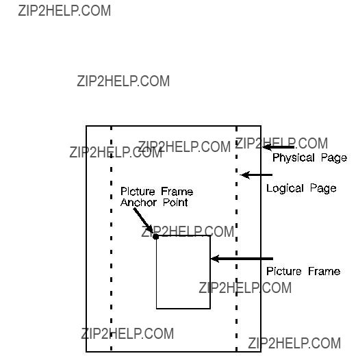
In addition to text and raster graphics,
Picture Frame.
Figure
Printable Area
The printable area is the area of the physical page in which the printer is able to place a dot. The physical page refers to the size of the media (letter, legal, etc.) installed in the printer.
The relationship between physical page, logical page, default picture frame, and printable area is defined in Table
Table

Table
The HP LaserJet printers perform

3 The Print
Environment

Factory Default Environment
A factory default is a feature setting programmed into the printer at the factory. The group of all of the printer???s feature settings set to their factory settings is referred to as the Factory Default Environment. These features are described in this manual. Since the
1.The font characteristics are determined by the default font. The default font can be the factory default font or the
2.User default values may be selected by the user from the printer???s control panel for these items.
3.Selectable from the printer control panel if duplex is selected.
4.Selectable from the printer???s control panel if a
5.Selectable from the printer???s control panel if a proportional scalable font has been selected as the user default.
Table
User Default Environment
There are several PCL features in the printer for which user defaults may be selected from the printer???s control panel. User default settings are stored in the User Default Environment and are retained even if the printer is turned OFF. Some of these features are listed below (for a complete set of the control panel user default features refer to Chapter 3 of the PCL 5 Comparison Guide.)
Refer to the printer User???s Manual for instructions on how to select these user defaults from the control panel.
The PJL (Printer Job Language) ???SET??? command overrides the PCL user default environment for the duration of a PJL job. If PJL is not active, then the PCL user default environment has precedence. Refer to ???PCL Commands??? in Chapter 1 for more information.
1.For scalable typefaces:
2.Selectable only if duplex is On.
Modified Print Environment
The current printer feature settings constitute the Modified Print Environment. Whenever a feature setting is altered using escape sequences, the new setting is recorded in the Modified Print Environment.
The Modified Print Environment is saved during a macro call or overlay and restored upon its completion.
A Modified Print Environment consists of the current settings for the items listed in Table

Resetting the Print Environment
Resets are used to return the printer to a known environment. Depending on the type of reset performed, the printer returns to either the User Default Environment or the Factory Default Environment.
command, and also enters PJL Mode of operation for printers that support PJL (refer to ???Universal Exit Language Command??? in Chapter 4 for more information). The ECE command should be included to ensure backward compatibility (the UEL command is ignored if received by a printer that does not support PJL).
Cold Reset
A Cold Reset restores the Factory Default Environment which includes resetting the control panel items to their factory default settings. A Cold Reset is performed by power cycling the printer while holding [ON LINE] until a 08 COLD RESET is displayed.

4 PCL Job Control
Commands
Introduction
A job typically consists of three parts:
zCommands providing job control.
zCommands providing page control.
zPrint data.
Table
1.If a number of consecutive pages within a job have the same format (such as margins, VMI, HMI, etc.), the associated page control commands only need to be sent once for that group of pages.

This chapter describes the commands providing job control. Job control commands are usually grouped together and sent at the beginning of a job. Page control commands and data are associated with each printed page of a job. Job control commands include the following:
zPrinter Reset.
zUniversal End of Language/Start of PJL.
zNumber of Copies.
zSimplex/Duplex Print.
zLeft and Top Offset Registration.
zDuplex Page Side Selection.
zJob Separation.
zOutput Bin Selection.
zUnit of Measure.
Printer Reset Command

Universal Exit Language Command
The Universal Exit Language (UEL) command causes the PCL printer language to shut down and exit. Control is then returned to the Printer Job Language (PJL). Both PCL 5 and
? % ??? 1 2 3 4 5 X
The UEL Command
Number of Copies Command
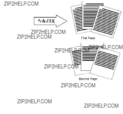
The Number of Copies command designates the number of printed copies of each page.
? & l # X
#= Number of copies (1 to 32767 maximum)
Default = 1 (Configurable from control panel)
Range =
(Values 32767 execute as 32767 values 1 are ignored. Maximum number of copies=99 for LaserJet II, IIP, III, IIID, IIIP and earlier LaserJet printers.)
This command can be received anywhere within a page and affects the current page as well as subsequent pages.
Example
To print 3 copies of a page, send:
?&l3X

Simplex/Duplex Print Command
This command designates either simplex or duplex printing mode for duplex printers. Simplex mode prints an image on only one side of a sheet (page). Duplex mode prints images on both sides of a sheet.
? & l # S
Figure
Figure
Left Offset Registration Command
The Left
? & l # U
The registration commands may cause data loss by moving the logical page outside the printable area.
This command has the same effect regardless of orientation.
This command can be used in both simplex and duplex modes.

Top Offset Registration Command
The Top
? & l # Z
The registration command may cause data loss by moving the logical page outside the printable area.
This command has the same effect regardless of orientation.
This command can be used in both simplex and duplex modes.

Figure
Figure
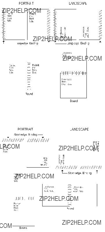
Duplex Page Side Selection Command
The Duplex Page Side Selection command causes a Form Feed and designates which side of the sheet to print.
The ability to skip a page while duplexing may be required at certain locations in a document. For example, a chapter typically begins on the front side of a page.
?&a#G
# = 0 - Select next side 1 - Select front side 2 - Select back side
Default = 0
Range =
If this command is received by a printer which does not have duplex or if duplexing is not enabled, these commands just eject the current page (sheet), positioning the cursor at the default position on the next page.
Example
To print on the front side of a page, regardless of the current side, send the following:
?&a1G
In this example, if the printer is currently formatting a front side, it will stop formatting, eject that page (sheet, skipping the back side), and begin printing on the next front page.

Job Separation Command
Job separation provides a means of identifying one print job from others in the printer???s output tray. It usually does this by physically offsetting one print job from the next.
The Job Separation command toggles the printer???s separation mechanism. This command must be sent between each job to enable the separation mechanism.
? & l 1 T

Output Bin Selection Command
The Output Bin Selection command selects either of the two output paper bins (upper or lower [rear]) for paper output.
? & l # G

Unit of Measure Command
The Unit of Measure command establishes the unit of measure for PCL Unit cursor movements.
The value field defines the number of
zVertical Cursor Position (PCL Units).
zHorizontal Cursor Position (PCL Units).
zVertical Rectangle Size (PCL Units).
zHorizontal Rectangle Size (PCL Units).
In addition, the current unit of measure setting affects the HMI setting, which in turn determines how cursor movement values are rounded. This affects the result of the following commands:
zHorizontal Cursor Position (Columns).
zHorizontal Tab (HT control code).
zSpace (SP control code).
zBackspace (BS control code).
zBitmap Character Delta X (???Delta X (SI),??? Chapter 11).
For example, if the unit of measure is set to 96 (one PCL Unit = 1/96 inch), then the HMI is rounded to the nearest 1/96 inch. If the unit of measure is set to 300 (one PCL Unit = 1/300 inch), the HMI is rounded to the nearest 1/300 inch.

The current unit of measure setting affects all PCL Unit moves, horizontal and vertical rectangle size, bitmap and scalable font metrics (how the cursor moves after printing a character). The Unit of Measure command does not affect the interpretation of binary raster data (bitmap fonts, raster graphics or patterns).
Once the units of measure is changed, it stays in effect until another is selected or the printer is reset. A control panel or ? E reset returns the current unit of measure setting back to the device default setting (300).
The units value is part of the modified print environment. As such, it is saved and restored whenever a macro is called or an overlay invoked, and defaulted when establishing the overlay environment in preparation for an overlay.
Figure

5 Page Control
Commands

Page Size Command
The Page Size command designates the size of the paper which in turn defines the size of the logical page.
? & l # A
PAPER:
#= 1 - Executive (7?? x 10?? in.) 2 - Letter (8?? x 11 in.)
3 - Legal (8?? x 14 in.)
6 - Ledger (11 x 17 in.)
26 - A4 (210mm x 297mm)
27 - A3 (297mm x 420mm)
ENVELOPES:
Upon receipt of this command any unprinted pages are printed, the top margin, text length, and left and right margins are set to their user defaults, and any automatic macro overlay is disabled. The cursor is moved to the left edge of the logical page at the top margin on the following page (see Figure
The factory default Page Size is Letter (A4 for 220v option printer); however, a user default Page Size may be selected from the control panel. The Page Size command takes precedence over the printer???s control panel FORM setting.

PAPER SOURCE COMMAND
The Paper Source command designates the location to feed paper, or it prints the current page.
? & l # H
#= 0 - Print the current page
(paper source remains unchanged).
1 - Feed paper from the a
3 - Feed envelope from manual input.
4 - Feed paper from lower tray.
5 - Feed from optional paper source.
6 - Feed envelope from optional envelope. feeder1
1 Must be used in conjunction with Page Size command, envelope selection.
the PCL 5 Comparison Guide or the printer User???s Manual for paper source feature implementation details for specific HP LaserJet printers.
The Paper Source command causes the current page to be printed and the cursor to be moved to the left edge of the logical page at the top margin position for the next page (see Figure
Example
To feed paper from the manual feed slot, send:
?&l2H
If the selection requires operator action (such as manually feeding paper), a printer message appears in the display, prompting for the appropriate action (see the printer User???s Manual for specific behavior).

Logical Page Orientation Command
Orientation defines the position of the logical page and the default direction of print with respect to the physical page as shown in Figure
? & l # O
#= 0 - Portrait
1 - Landscape
2 - Reverse Portrait
3 - Reverse Landscape
Default = 0
Range =
Notes
Note
This command can be used only once per page. To print multiple directions per page use the Print Direction command.
This command affects the
The Orientation command causes the page length, top margin, text length, left and right margins, horizontal motion index (HMI), and vertical motion index (VMI) to return to their user default values, and disables the automatic macro overlay. All data received prior to this command is printed, and a Form Feed and Carriage Return executed. The cursor is moved to the left edge of the logical page at the top margin cursor position (see Figure
The factory default orientation is portrait. Landscape orientation may be selected as the user default orientation using the control panel.
The HP LaserJet 2000, LaserJet IID, LaserJet IIP and all PCL 5 printers automatically rotate all fonts to the current orientation.
Table
Table

Figure
The orientation of the
Most

Figure

Print Direction Command
The Print Direction command rotates the logical page coordinate system with respect to the current orientation without performing a page eject. This rotation is performed in 90?? increments in a counterclockwise direction. This allows printing in four directions on the same page.
? & a # P
#= 0 - 0?? rotation.
90 - 90?? ccw rotation.
180 - 180?? ccw rotation.
270 - 270?? ccw rotation.
example, rotating a default page (portrait orientation, 0?? print direction) 90?? causes data to print in the landscape direction across the ???portrait??? page.
z The margins are translated (when the print direction changes by 90??, the left margin becomes the new top margin, the former top margin becomes the new right margin, etc.)

Figure
Text Area

Figure
Left Margin Command
The Left Margin command sets the left margin to the left edge of the specified column.
? & a # L
#= Column number
Default = Column 0 (Left bound of logical page)
Range = 0 - Right margin
The first column within a line is column 0, which is located at the left edge of the logical page (the HMI setting defines the distance between columns, which thereby defines the maximum number of columns on the logical page). If the value field specifies a column greater than the current right margin, the command is ignored.
Margins represent a physical position and once set do not change with subsequent changes in HMI.
If the cursor is to the left of the new left margin, the cursor is moved to the new left margin.
Example
To set the left margin to column 5, send:
?&a5L
Right Margin Command
The Right Margin command sets the right margin to the right edge of the specified column.
? & a # M
#= Column number
Default = Logical Page right bound
Range = Current left margin - Logical page right bound
The maximum right column is located at the right edge of the logical page (the HMI setting defines the distance between columns, which thereby defines the maximum number of columns on the logical page). If the value field specifies a column which is greater than the right edge of the logical page, the right margin is set to the right edge of the logical page. If the value field specifies a column less than the left margin, the command is ignored.
Margins represent a physical position and once set do not change with subsequent changes in HMI.
If the cursor position is to the right of the new right margin, the cursor is moved to the new right margin.
Example
To set the right margin to column 45, send:
?&a45M
Clear Horizontal Margins Command
The Clear Horizontal Margins command resets the left and right margins. The left margin is set to the left edge of the logical page (column 0) and the right margin is set to the right edge of the logical page.
? 9

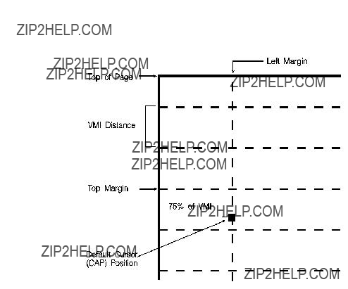
Top Margin Command
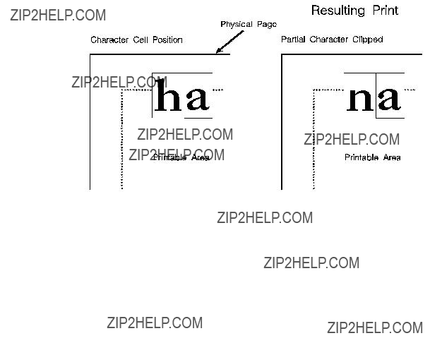
The Top Margin command designates the number of lines between the top of the logical page and the top of the text area.
The cursor is actually positioned down 75% of the VMI distance (0.75 ??? VMI) from the top margin. This positions the cursor at the relative base line position of a character cell for correct character positioning.
Example
To set the top margin to line 4, send:
?&l4E
Figure

Text Length Command
The Text Length command designates the number of lines (at a given VMI) within the logical page available for printing text, the text area. This effectively defines the bottom margin.
? & l # F
#= Number of lines
Default = 1/2 inch less than maximum text length1
Range = Logical page length minus top margin
1 Maximum text length = INT(logical page length - top margin). However, if the max text length is less than ??inch, the text length is set to the maximum allowable.
The value field (#) sets the text length in lines referenced from the top margin. If a value greater than the logical page length minus the top margin is specified or if the current VMI is 0, the command is ignored. The user default text length is invoked whenever the orientation, page length, page size, or top margin is changed. The user default text length is computed as follows:
Example
To select a text length of 60 lines, send:
?&l6??F

Perforation Skip Command
The perforation region is the distance from the bottom of the text area of one page to the top of the text area (top margin) of the next page. When perforation skip is enabled, a Line Feed or
? & l # L

Horizontal Motion Index (HMI) Command
The Horizontal Motion Index (HMI) command designates the width of the columns.
? & k # H
current unit of measure setting. For example, if the unit of measure is set to 96 (one PCL Unit = 1/96 inch), then the HMI is rounded to the nearest 1/96 inch. If the unit of measure is set to 300 (one PCL Unit = 1/300 inch), the HMI is rounded to the nearest 1/300 inch.
Example
To print the printer???s resident 16.66 pitch Line Printer font at 17.75 cpi, send ?(s16.66H to select the Line Printer font, then send the command ?&k6.76H to change HMI. This value field is calculated as follows:
Each character then occupies 6.76/120 inch or 1/17.75 inch.
To use Courier 12 point (10 cpi) and print 80 characters across A4 paper, requires adjusting the HMI value. The HMI value is calculated as follows:
* This value was obtained from Figure

Vertical Motion Index (VMI) Command
The Vertical Motion Index (VMI) command designates the height of the rows. (The vertical distance the cursor moves for a Line Feed operation.)
? & l # C
#= number of 1/48 inch increments between rows.
Default = 8
Range = 0 - Current logical page length up to a maximum of 32767
If the specified VMI is greater than the current logical page length, the command is ignored.
The value field is valid to 4 decimal places. A ?? in the value field indicates no vertical movement.
This command affects the Line Feed and
The factory default VMI is 8, which corresponds to 6
Example
To designate a VMI of 6 (8
?&l6C (6/48 = 1/8 inch/line)
The following equation converts
Common VMI Settings
To print 66 lines per page on
?&l7.27C 7.27 = (10/66) x 48
To print 66 lines per page on letter or
?&l5.45C 5.45 = (7.5/66) x 48

Line Spacing Command
The Line Spacing command sets the number of lines printed per inch. Only the values listed below are valid.
? & l # D
6 Cursor Positioning
Introduction
This section describes the cursor positioning commands.
Although the printer does not actually have a cursor, the PCL cursor position refers to the Current Active Position (CAP), like the blinking underline character (cursor) used on most computers. This ???cursor??? identifies the current position on the page; the pointer, where a printing command begins laying out page data. The cursor can be moved anywhere within the logical page using a combination of horizontal and vertical cursor positioning commands and control codes.
In addition to cursor commands positioning the cursor, the cursor is automatically positioned after certain operations, such as printing characters and graphics. After printing a character, the cursor is positioned to the right, at a distance equal to the width of that character. This is controlled by the character design described under ???Character Width??? in Chapter 10, and allows printing characters without requiring a cursor position command for each character printed. When printing graphics, the cursor can also be positioned at a new location. These new positions are identified in the graphics sections.
Vector Graphics.

Absolute vs. Relative Cursor Positioning
Either absolute or relative motion can be specified.
Absolute motion always specifies the distance to move referenced from the top margin at the left bound of the logical page (0,0), regardless of the current active position (CAP) (see Figure
Relative motion specifies the distance to move referenced from the current active position (CAP) (see Figure
Figure
Cursor Positioning Units
Cursor positioning is done in PCL coordinate system units. The units of the
PCL Units
The current unit size used in PCL Unit moves is determined by the value specified in the Unit of Measure command, defining the number of
zVertical Cursor Position (PCL Units).
zHorizontal Cursor Position (PCL Units).
zVertical Rectangle Size (PCL Units).
zHorizontal Rectangle Size (PCL Units).
In addition, the current unit of measure setting affects how cursor movement values are rounded, in turn affecting the result of the following commands:
zHorizontal Cursor Position (Columns).
zHorizontal Tab (HT control code).
zSpace (SP control code).
zBackspace (BS control code).
zBitmap Character Delta X (Delta X (SI), Chapter 11).
For more information, refer to the next section, ???Horizontal Cursor Positioning (Columns) Command.???
If no unit of measure value is specified, the default number of
Decipoints
In PCL terminology, a decipoint is 1/720 inch or
Columns & Rows
The width of a column is defined by the current horizontal motion index (HMI), as described under ???Horizontal Motion Index (HMI) Command??? in Chapter 5. The distance between rows is defined by the current vertical motion index (VMI), as described under ???Vertical Motion Index (VMI) Command??? in Chapter 5. HMI is the distance between consecutive characters. VMI is the distance between consecutive lines of text. HMI and VMI are described in more detail in Chapter 5.

Horizontal Cursor Positioning (Columns)
Command
This Horizontal Cursor Positioning command moves the cursor to a new column on the current line.
? & a # C
A value field (#) with a plus sign (+) indicates the new position is to the right of and relative to the current cursor position; a minus sign
If a request is made for a location outside the printer???s logical page, the CAP is moved to the appropriate logical page limit.
Horizontal Cursor Positioning (Decipoints)
Command
This Horizontal Cursor Positioning command moves the cursor to a new position along the horizontal axis.
? & a # H
#= Number of Decipoints (1/720 inch)
Default = NA
Range = 0 - logical page right bound (rounded to the first decimal place)
A value field (#) with a plus sign (+) indicates the new position is to the right of and relative to the current cursor position; a minus sign
If a request is made for a location outside the printer???s logical page, the current active position (CAP) is moved to the appropriate logical page limit.
The value field is valid to two decimal places.
Horizontal Cursor Positioning (PCL Units)
Command
This Horizontal Cursor Positioning command moves the cursor to a new position along the horizontal axis.
? * p # X

Horizontal Cursor Positioning Control Codes
Four control codes can be used to position the cursor horizontally on the current line. These control codes are explained below.
CR - Carriage Return
Moves the current active position (CAP) to the left margin on the current line. (Refer to ???Line Termination Command??? later in this chapter.)
SP - Space
Moves the current active position (CAP) to the right by one column position. Space may be a printable character or a control code. If a character is defined for the Space code, Space is printable; otherwise, it is a control code. For proportionally spaced fonts, a Space control code moves the cursor by the current HMI value; however, a printable space moves the cursor the width of the character. For fixed pitch fonts, a space, whether control code or printable, moves the cursor according to the HMI value.
BS - Backspace
Moves the current active position (CAP) left a distance equal to the width of the last printed symbol or space. If the active position is already at the left margin, no action is taken. If the cursor is currently beyond the right margin, BS positions the cursor just to the left of the right margin. When using fixed pitch fonts, the Backspace distance is defined by the current print pitch (HMI setting).
When using
Multiple backspaces each move back the distance of the last printed symbol or space. For example, if ???world??? was printed with a proportional font and then 5 backspaces were performed, the distance moved back would be five times the width of the ???d.???
HT - Horizontal Tab
Moves the current active position (CAP) to the next tab stop on the current line. The tab stops are at the left margin and every 8th column between the left margin and the right bound of the logical page. If the new horizontal position crosses the right margin, the new horizontal position is set to the right margin. If the current HMI value is 0, the command is ignored.

Vertical Cursor Positioning (Rows) Command
This Vertical Cursor Positioning command moves the cursor to a new line in the same column position.
? & a # R
If a request is made for a location outside the printer???s logical page, the current active position (CAP) is moved to the appropriate logical page limit.

Vertical Cursor Positioning (Decipoints)
Command
This Vertical Cursor Positioning command moves the cursor to a new position along the vertical axis.
? & a # V
If a request is made for a location outside the printer???s logical page, the current active position (CAP) is moved to the appropriate logical page limit.

Vertical Cursor Positioning (PCL Units) Command
This Vertical Cursor Positioning command moves the cursor to a new position along the vertical axis.
Note
Note
? * p # Y
#= Number of PCL Units
Default = NA
Range =
A value field (#) with a plus sign (+) indicates the new position is downward from and relative to the current cursor position; a minus sign
Since the top margin can be changed using a printer command, the physical location of the point (0,0) may change. This affects the cursor position on the page.
If a request is made for a location outside the printer???s logical page, the current active position (CAP) is moved to the appropriate logical page limit.
The current unit size used in PCL Unit moves is determined by the value specified in the Unit of Measure command. If no other value is specified, the number of
The
? =
Vertical Cursor Positioning Control Codes
Two control codes can be used to position the cursor vertically. These control codes are explained below.
LF - Line Feed
Advances the current active position (CAP) to the same horizontal position on the next line. The distance to the next line is defined by the current line spacing (defined by the last VMI or line spacing setting). (Refer to ???Line Termination Command??? later in this chapter.)
FF - Form Feed
Advances the current active position (CAP) to the same horizontal position at the top of the text area on the next page. (Refer to ???Line Termination Command??? later in this chapter.)
Line Termination Command
The Line Termination command controls the way the printer interprets CR, LF, and FF control characters. All CR, LF and FF control characters received after the Line Termination Command are interpreted as shown below.
? & k # G
#= 0- CR=CR; LF=LF; FF=FF
1-
2- CR=CR;
3-
Default = 0
Range =
For example, if a value field of 1 is sent, the printer interprets each Carriage Return (CR) received as a Carriage Return (CR) and Line Feed (LF) control code. A Line Feed or Form Feed would be sent as is.
If a value of 3 is sent, the printer interprets each Carriage Return (CR) received as a Carriage Return (CR) and Line Feed (LF); it interprets each Line Feed (LF) received as a Carriage Return (CR) and Line Feed (LF); and it interprets each Form Feed (FF) received as a
Carriage Return (CR) and Form Feed (FF).

Push/Pop Cursor Position Command
The Push/Pop Cursor Position command allows the current cursor position to be stored and recalled.
A value field of 0 pushes the cursor position onto the stack, leaving the current position unaffected. A value field of 1 pops the position from the stack, restoring it as the current cursor position.
Twenty positions may be pushed. If you try to save more than 20 positions, the command is ignored. If you try to restore more
positions than were pushed, the command is ignored. A printer reset restores the current active position stack to the top (all saved positions are discarded).
The positions stored in the stack are not changed with an orientation change. Therefore, the positions are relative to the top left corner of the current orientation. Also, a position pushed in one orientation and popped in another can result in a position that is outside the logical page. If the position popped is outside the current logical page, the position is moved to the appropriate logical page limit.
7 Fonts
Introduction
A font is a group of symbols that have similar characteristics. A font is described by its symbol set, spacing, height, pitch, style, stroke weight, typeface and orientation.
A typical document is printed using several fonts. A large font may be used for the title and chapter headings of a document, a standard size font may be used for the body of the document, and key words or phrases may be highlighted, using a bold or italic font.
For example, this text is printed using a Century Schoolbook typeface; its height is 10 point, its style is upright, and its stroke weight is medium. Examples of different fonts are shown in Figure
Figure
A font must be selected for printing by the user. One font is selected at a time. It is selected by identifying the specific characteristics of the font. Font selection commands identify font characteristics to the printer (refer to Summary of Font Selection by Characteristic for detailed font selection information).
PCL 5 printers feature scalable fonts. With the addition of this feature, the printer has two font formats available: bitmap and scalable. A bitmap font is available in its one, defined size only. A scalable font, on the other hand, can be selected (scaled) for a range of sizes (refer to ???Bitmap Fonts and Scalable Typefaces??? later in this chapter for additional information).
Font Sources
A number of fonts (and typefaces, as described later) are supplied with the printer. These fonts reside in permanent ROM (read only memory), and are referred to as internal fonts. Additional fonts can be added easily by inserting font cartridges or SIMM modules into the printer, or downloading them from the host computer.
A cartridge font plugs into a font cartridge slot on the printer.
SIMM font modules plug into a printed circuit board inside the printer. These
Soft fonts are supplied as files on flexible disk transferred (downloaded) into the printer???s user (RAM) memory. Once a soft font has been downloaded into the printer???s RAM, it may be selected for printing.
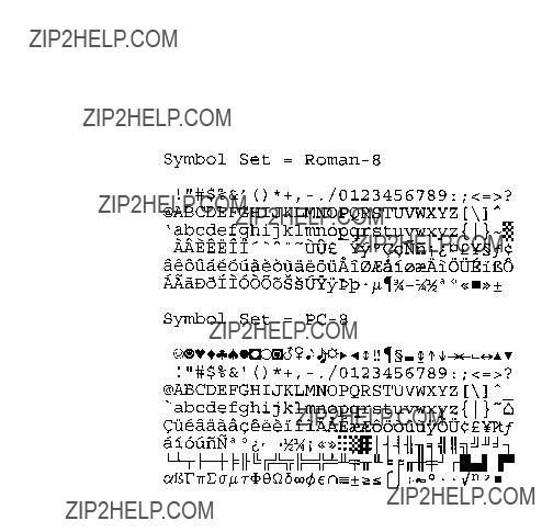
Symbol Set
Symbol set identifies the specific collection of symbols provided by a font. Each symbol set is defined with a specific application in mind. For example, the legal and math symbol sets were designed to support legal and scientific applications. The following figure shows two common symbol sets,
Figure

Spacing
Another characteristic that differentiates fonts is spacing. Fonts have either fixed or proportional spacing.
Figure
Figure

Pitch
Pitch describes the number of characters printed in a horizontal inch. Pitch only applies to
Figure
Height
The height of a font is the measurement of the body of the type in PCL points. A PCL point is 1/72 inch in bitmap fonts, and approximately 1/72 inch in scalable fonts. The body of the type is slightly larger than the distance from the bottom of a descender to the top of an unaccented capital letter.
Figure
This loose measure from near the bottom of a descender to just above the top of an unaccented capital letter is sometimes referred to as the ???Em.???

Style
Style is defined by three characteristics: posture (upright, italic), width (condensed, normal, expanded, etc.), and structure (solid, outline, shadow etc.). Examples of upright and italic styles are shown.
Figure
Stroke Weight
Stroke weight describes the thickness of the strokes that compose characters. Examples of medium and bold stroke weights are shown in the figure below.
Figure

Typeface Family
Typeface identifies the design of the symbols of the font. Each typeface family has unique and distinguishing design characteristics. The following example shows typefaces from various typeface families.
Figure

Orientation
Orientation defines the position of the logical page with respect to the physical page as shown in Figure
Figure
The HP LaserJet IID, IIP, 2000, and all PCL 5 LaserJet printers automatically rotate fonts to the current orientation (all fonts are available in all four orientations). (Earlier printers required fonts in the orientation which matched the orientation of the page. Thus, orientation is not as important as it once was.)
The orientation of a font is still a consideration when the amount of user memory (RAM) is a concern. Internal and other

Bitmap Fonts and Scalable Typefaces

Figure
Figure
Internal Fonts
Internal fonts are those fonts that are provided with the printer.
Both internal bitmap and scalable font formats are provided. Internal bitmap and scalable fonts and symbol sets for current models of HP LaserJet family printers are listed in Chapter 2 of the PCL 5 Comparison Guide. Font and symbol set listings for earlier printer models can be found in the User???s Manual for each printer.
Special Effects
HP PCL 5 printers allow you to create special effects when printing characters. These effects are achieved through the use of the print model feature, or through the use of
The print model provides a simple means for printing patterned or shaded characters using the printer???s predefined

8 PCL Font Selection
Introduction
Several characteristics identify a font (as described in Chapter 7, Fonts). Font characteristic selection commands, described in this chapter, are used to specify the desired font characteristics for printing. Commands are included for the following characteristics: symbol set, spacing, pitch, height, style, stroke weight, and typeface family.
The printer maintains a font select table in its operating code that contains the characteristic values of the current font. Whenever the printer receives a font select command (escape sequence) specifying a new characteristic value, the printer records that characteristic in the table. After the table is updated (receives new characteristic values), and text is ready to be printed, the printer performs a font select. The printer searches the available fonts and scalable typefaces to select one that matches (or most closely matches) the characteristics as listed in the font select table.
Font Selection Priority
The printer selects a font based on a prioritization of its design characteristics, then its resolution, then its physical location in the printer, and finally, its orientation. Font selection priority considerations are shown in the following list:
1.Bitmap fonts designed at 600 dpi are not available for selection at 300 dpi. In 600 dpi mode, font priority is as follows: 600 dpi bitmap, scalable, 300 dpi bitmap.
2.Although location is not a font characteristic, it is a font selection consideration.
When selecting a font, the printer compares the highest priority characteristic in the font select table to the corresponding characteristic of the available fonts. If only one font is available that matches, that font is selected. If several fonts match, the printer compares the next highest priority characteristic to the corresponding characteristic of the available fonts and so on down the list. When only one font remains, that font is selected. However, if after comparison of all the font design characteristics, more than one font still remains, then the resolution and location are considered.

There are four locations where a font may be stored: printer ROM (Read Only Memory), SIMM module ROM, cartridge ROM, and printer RAM (random access memory; user memory). These font locations are shown below, listed from the highest to lowest priority. The font that matches the characteristics is selected from the highest priority location.
Priority of Locations
1.In printers with two cartridge slots, one slot has priority over the other. Refer to Appendix E of the PCL 5 Comparison Guide for cartridge slot priority information for the different HP LaserJet printers.
Font Select Table
The initial font specification in a job should be made using all of the font characteristics.
To select a
To subsequently select a font with the same characteristics differing only in one aspect, only the single characteristic must be specified. For example, to select a font differing only in stroke weight (in this case, medium rather than bold), the printer???s font select table could be changed as follows:

Primary and Secondary Fonts
The printer maintains two independent font select tables for use in selecting a primary font and a secondary font. All of the characteristics previously described apply to both tables. This provides access to two distinct fonts, only one of which is selected
at a given time. To alternate between the primary and the secondary font, the control codes ??????SI?????? (Shift In; ASCII 15) is used to designate primary and ??????SO?????? (Shift Out; ASCII 14) is used to designate secondary.
The factory default state is primary font designated.
Font Resolution
With the introduction of the LaserJet 4 printer, fonts can be printed at 600 dpi resolution. All scalable fonts automatically print at either 300 or 600 dpi resolution. A bitmapped font which was designed at 300

Symbol Set Command
The Symbol Set command identifies the specific set of symbols in a font. ???Symbols??? are the alphanumeric, punctuation, or any other printable characters or symbols which may be included.
EC ( ID Primary Symbol Set Command
ID = Symbol Set ID value (see Appendix C in the PCL 5
Comparison Guide)
EC ) ID Secondary Symbol Set Command
If the font is a scalable typeface, symbol set is determined from the values contained in the printer???s font selection table. To specify a different symbol set, send a symbol set selection command prior to the Font Selection ID command. (Also see ???Font Selection by ID Command,??? later in this chapter.)

A few symbol sets are listed below. For a more complete list, refer to Appendix C in the PCL 5 Comparison Guide.
Example
To specify ASCII as the symbol set for the primary font, send:
EC(0U
To specify
EC)8U
The HP LaserJet printers provide several
Spacing Command
When proportional spacing is specified and a
For
The user default primary and secondary spacings are implicitly set by selection of a user default font from the printer???s control panel (refer to the printer User???s Manual).
Example
To specify proportional spacing for the primary font, send:
EC(s1P
To specify fixed spacing for the secondary font, send:
EC)s0P
Pitch Command
The Pitch command designates the horizontal spacing of a fixed- spaced (bitmap or scalable) font in terms of the number of
characters per inch. This characteristic is ignored when selecting a
EC ( s # H - Primary pitch
EC ) s # H - Secondary pitch
#= # = Pitch in characters/inch
Default = 10
Range = 0.00
The value field (#) is valid to two decimal places.
If a pitch is specified that is not available, the next greater available pitch is selected. If no greater value is available, the closest available lesser value is selected.
The factory default primary and secondary pitches are ten characters per inch.
The user default primary and secondary pitches are implicitly set by selection of a users default font from the printer???s control panel (refer to the printer User???s Manual).
The range of valid pitch selections for a
The lower end of the pitch range is limited as a result of the font height limitation of 999.75 points. For example, the smallest available pitch for the internal Courier typeface would be about 0.12.
The upper end of the pitch range is similarly limited by the minimum recommended font height of 4 points. For Courier, this translates to a maximum recommended pitch of 30 (30 cpi), while for Letter Gothic the maximum recommended pitch is 36. When requested pitch values are outside of HP???s recommended limits, unsatisfactory results can occur.
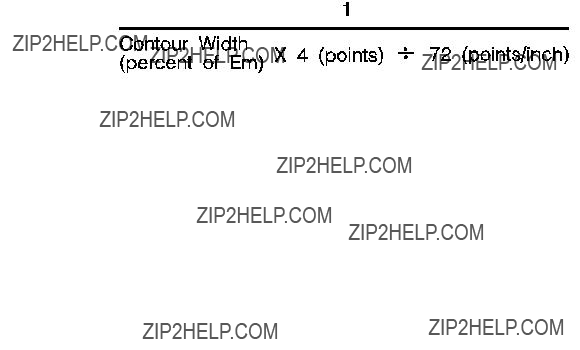
The following formula can be used to as a rule of thumb for computing a maximum recommended pitch:
Example
To specify 10 pitch for the primary font, send:
EC(s10H
To specify 16.66 pitch for the secondary font, send:
EC)s16.66H
Height Command
The Height command specifies the height of the font in points. This characteristic is ignored when selecting a
EC ( s # V - Primary Height
EC ) s # V - Secondary Height
#= Height in points
Default = 12
Range = 0.25 - 999.75
The value field (#) is valid to two decimal places. If the requested height is unavailable, the closest height is selected. All bitmap fonts whose heights are within a quarter point of the specified height are considered to have the specified height. For scalable fonts the value field is from .25 to 999.75 points in increments of 0.25 point (values are rounded to the nearest quarter point).
The factory default primary and secondary heights are 12 point. In PCL bitmap fonts, a point is 1/172 (0.01389) inch. For scalable fonts, the definition of a point varies in TrueType a point is 1/172 inch, while Intellifont fonts have 72.307 points to the inch.
The user default primary and secondary heights are implicitly set by selection of a user default font from the printer???s control panel (refer to the printer User???s Manual).

Example
To specify a height of 12 points for the primary font, send:
EC(s12V
To specify a height of 14.4 points for the secondary font, send:
EC)s14.4V
If the above sequence was used for selection of a scalable font, the actual font would be scaled to 14.5 points.
Style Command
The Style command identifies the posture of a character, its width, and structure of the font symbols.
EC ( s # S - Primary Style
EC ) s # S - Secondary Style
Default = 0
Range = 0 - 32767 (values greater than 32767 are set to 32767)
Style values for the most common typefaces are listed in Table
Table

Example
To specify an upright style for the primary font, send:
EC(s0S
To specify an italic style for the secondary font, send:
EC)s1S
Figure
Stroke Weight Command
The Stroke Weight command designates the thickness of the strokes that compose the characters of a font.
EC ( s # B - Primary stroke weight
EC ) s # B - Secondary stroke weight
Default = 0
Range = - 7 to 7 (less than
The value field (#) specifies the thickness of the strokes used in the design of the font. The supported stroke weight values are
Table

If the specified stroke weight is greater than or equal to 0 and is not available, the next thicker available stroke weight is selected. If no thicker stroke weight is available, the closest available thinner stroke weight is selected.
If the specified stroke weight is less than zero and is not available, the next thinner available stroke weight is selected. If no thinner stroke weight is available, the closest available thicker stroke weight is selected.
The factory default primary and secondary stroke weights are zero (medium).
The user default primary and secondary stroke weights are implicitly set by selection of a user default font from the printer???s control panel (refer to the printer User???s Manual).

Typeface Family Command
The Typeface Family command designates the design of the font.
If the value field (#) specifies a typeface that is unavailable, this characteristic is ignored during font selection.
The factory default primary and secondary typefaces are Courier.
The user default primary and secondary typefaces are implicitly set by selection of a user default font from the printer???s control panel (refer to the printer User???s Manual).
There is some variation in how font selection occurs between HP LaserJet models. The typeface selection compatibility for two types of values is identified for various HP LaserJet printers in Chapter 2 of the PCL 5 Comparison Guide.
1.These values are not applicable to all HP LaserJet family printers. See the
PCL 5 Comparison Guide for specifics.
Some typeface
C in the PCL 5 Comparison Guide.
Example
To specify CG Times as the typeface family for the primary font, send:
EC)s4101T
To specify Line Printer as the typeface family for the secondary font, send:
EC)s0T
Orientation
The Orientation command (EC&l#O) designates the position of the logical page with respect to the physical page. Earlier printers could only print bitmap fonts and raster graphics in the orientation for which they were designed. However, the HP LaserJet IID, IIP, 2000, and all PCL 5 HP LaserJet printers have the capability to automatically rotate bitmap fonts and raster graphics to match the page orientation; therefore, all fonts are available in all four page orientations and print directions. Whenever a scalable font is selected, it is created in the current orientation for printing. Refer to ???Logical Page Orientation Command??? and ???Print Direction Command??? in Chapter 5 for more information.
Font Selection Examples
Bitmap,
This example illustrates how to select a primary, bitmap, Line Printer,
Table
The following escape sequences can be sent to the printer to select a primary font with the above characteristics:
EC(0UEC(s0PEC(s16.66HEC(s8.5VEC(s0SEC(s0BEC(s0T
The previous sequence can be shortened by combining sequences that have the same two characters following the EC character:
EC(0UEC(s0p16.66h8.5v0s0b0T

Scalable,
This example illustrates how to select a primary, scalable, CG Times,
Sending shortened font selection commands can result in selection of an unexpected font. This is due to failure to track previously specified characteristics and their selection priority in relation to the current font selection. Thus, it is recommended that all of the characteristics be sent to ensure that the correct font is selected.

Summary of Font Selection by Characteristic
The following summarizes the procedure the printer uses to select a font. Selection by characteristic is an elimination process. The nine steps are performed in the following order:
1Symbol Set - if the specified symbol set exists, that symbol set is selected; otherwise,
2Spacing - if proportional spacing is specified and available, proportional spacing is selected. If proportional spacing is specified but is not available, fixed spacing is selected in the current pitch. (A
3Pitch - applies only to fixed spaced fonts. If fixed spacing is specified and available, fixed spacing in the specified pitch is selected.
Bitmap Fonts: For a
Scalable Fonts: For a
4Height - the closest height available from the remaining fonts is selected. The closest height is in terms of absolute difference. All bitmap fonts whose heights are within a quarter point of the specified height are considered to have the specified height.

1.In printers with two cartridge slots, one slot has priority over the other. Refer to Appendix E of the PCL 5 Comparison Guide for cartridge slot priority information for the different HP LaserJet printers.
9Orientation - for bitmap fonts the last criteria considered for the selection is its orientation. If two fonts still remain and match in all the above characteristics except orientation, that font which matches the current page orientation is selected.
If there is a soft font (highest priority location) available that matches all selection characteristics, but is not in the current orientation, and there is an identical font available in a cartridge or internal font (lower priority location) that is in the current orientation, the soft font is selected and rotated.

Font Selectionby ID Command
Soft fonts can be specified using their associated ID numbers. (ID numbers are assigned to soft fonts using the Font ID command described in Chapter 9, Font Management).
EC ( # X - Designates soft font # as primary
EC ) # X - Designates soft font # as secondary
If the font is a scalable typeface, symbol set is determined from the values contained in the printer???s font selection table. To specify a different symbol set, send a symbol set selection command prior to the Font Selection ID command.
For shared or

Examples
To specify the font associated with ID number 7 as the primary font, send:
EC(7X
To specify the font associated with ID number 5 as the secondary font, send:
EC)5X
Select Default Font Command
The Default Font command sets all of the font characteristics to those of the user (control panel selected) default font.
In addition to selecting fonts using the PCL font selection commands, fonts can also be selected and printed in

Transparent Print Data Command
The Transparent Print Data command provides printing access to those characters which the printer normally defines as unprintable. These characters include decimal character codes 0,
EC & p # X [Transparent Print Data]
# =Number of bytes of transparent print data.
Default = N/A
Range = 0 - 32767
Each transparent print data byte is interpreted as a single character code. The appropriate character is printed if one exists; otherwise, a Space is processed. For example, control codes such as LF, CR, FF are treated as print data while in Transparent Print Data mode.
Underline Command
The Underline command controls automatic text underlining.
EC & d # D - Enable underline
#= 0 - Fixed position
3 - Floating position
Default = 0
Range = 0, 3 (values outside range are ignored)
EC & d @ - Disable underline
Once underlining is enabled, any positive horizontal movement causes an underline to be drawn. Positive horizontal movement includes the printing of text and positive horizontal cursor motion.
When fixed position underlining is enabled, the underline is drawn five dots below the baseline and is three dots thick. (The baseline is the dot row on which all of the characters in a given line appear to stand, see Chapter 11.) When floating position underline is enabled, the underline position is determined by the greatest underline distance below the baseline of all of the fonts printed on the current line. (The underline distance for a font is defined in the font header, see Chapter 11.)
9 Font Management
Introduction
Font management provides mechanisms for manipulating soft fonts. It provides the means for controlling which soft fonts are saved in user memory (RAM) or deleted. This is accomplished by assigning a font as either temporary or permanent, or deleting a soft font. In addition, font management includes the command for assigning ID numbers to RAM fonts. It also provides a mechanism for copying ROM fonts (internal, cartridge, or SIMM) to RAM for the purpose of assigning ID numbers.
Downloading Soft Fonts
The process of transferring soft fonts from a host computer to the printer???s user memory (RAM) is called downloading. Designate a unique identification (ID) number prior to the download of a font. This number is then associated with the soft font. This number is assigned using the Font ID command, described later in this chapter. Subsequent manipulation of the soft font is accomplished using the font???s ID number. If a font is already associated with this ID number in the printer, the existing font is deleted during the download.
Several commands are required to define a font before downloading it to the printer. These commands are described in detail in Chapter 11.
Once downloaded, a soft font occupies a portion of user memory (RAM). The number of soft fonts that can be stored in user memory is limited only by the amount of available user memory.

Temporary vs. Permanent Fonts
Once downloaded, a font is automatically designated as temporary. A temporary soft font is deleted from user memory during a printer reset or when a Typeface List, a Font Printout or a
Deleting Fonts
There are several mechanisms provided by PCL font management that delete soft fonts from user memory. These include commands to delete all soft fonts, all temporary soft fonts, or an individual soft font by reference to its font ID number (refer to the Font ID and the Font Control commands described on the following pages).

Font ID Command
The Font ID command is used to specify an ID number for use in subsequent font management commands. The ID number of a font can be used to select the font for printing (refer to ???Font Selection by ID??? in Chapter 8).
EC *c#D
Example
To specify a font ID number of 1, send:
EC*c1D

Font Control Command
The Font Control command provides mechanisms for manipulating soft fonts.
EC * c # F
#= 0 - Delete all soft fonts
1 - Delete all temporary soft fonts
2 - Delete soft font (last ID specified)
3 - Delete Character Code (last ID and Character Code specified)
4 - Make soft font temporary (last ID specified)
5 - Make soft font permanent (last ID specified)
6 - Copy/Assign current invoked font as temporary (last ID specified)
Examples
To remove all soft fonts from user memory, send:
EC *c0F
To remove only those soft fonts that are temporary, send:
EC *c1F
To delete the soft font with an ID of 1, send:
EC *c1d2F

To delete the character ???p??? (112 decimal) in a bitmap or bound scalable font with an ID of 1, send:
EC *c1d112e3F
(A space is printed in place of the deleted character. Also, the EC*c#E Character Code command used in the above sequence ???...112e...,??? is described in Chapter 11.)
To make the soft font with an ID of 2 temporary, send:
EC *c2d4F
To make the soft font with an ID of 2 permanent, send:
EC *c2d5F
Font Management Example
This example illustrates several typical font management operations. It assumes a bitmap soft font is stored and available on an
1 Set the font ID number to 2:
EC*c2D
2Download a soft font file using the
COPY /B filename PRN
Note that the soft font is associated with font ID 2.
3Make the soft font permanent to prevent its deletion during a printer reset:
EC*c5F
4 Designate the permanent soft font as primary:
EC(2X
Unbound Scalable Fonts
Prior to introduction of the HP LaserJet IIIP printer, a downloaded scalable font was restricted to a single symbol set. Now scalable fonts with no symbol set affiliation can be downloaded. These new fonts are called unbound fonts.
To download unbound fonts, the ???PCL Font Header for Intellifont Unbound Scalable Fonts??? or the ???Format 15 Font Header for Scalable Fonts??? (TrueType) must be used (see Chapter 11).
Bound and Unbound Fonts
The terms ???bound??? and ???unbound??? refer to the symbol set capacity of a font. A bound font identifies a font which is restricted (bound) to a single symbol set. An unbound font (or unbound typeface) indicates the capacity to be bound to a set of symbols selected from a complementary symbol index (such as the Master Symbol List (MSL), or the Unicode symbol index).
Font Selection and Unbound Fonts
When a font is requested for printing, the printer selects a font which most closely matches the current font selection characteristics (symbol set, spacing, pitch, height, style, stroke weight, and typeface). Refer to ???Summary of Font Selection by Characteristics??? in Chapter 8 for detailed font characteristic selection information.
Since symbol set is the highest font selection priority and typeface is the lowest, the printer searches for the symbol set first. A list of all fonts that match the requested symbol set is made. This includes bitmap, bound, and unbound fonts. Since bitmap and bound scalable fonts contain only one symbol set, they can be easily identified. However, determining which unbound fonts match a symbol set is more complex. Symbol set compatibility for unbound fonts is determined by identification of groups of symbols referred to as symbol collections.
Symbol Collections
The symbols in an unbound font (typeface) can be divided into symbol collections. These symbol collections identify the symbols according to some language basis or special application usage. Some symbol collections include: Basic Latin, East European, Turkish, Math,
The symbols within a symbol collection do not change from one unbound font to the next. For example, the Basic Latin collection always contains the same symbols. Different fonts may contain different symbol collections. For example, the internal Univers typeface contains the Latin, Math, and
When searching unbound scalable fonts (during font selection) for those that match the requested symbol set, the printer actually searches for symbol collections. To identify symbol collections which meet the needs of the requested symbol set, the printer uses two numbers: the Character Requirements number and the Character Complement number.
Character Complement Numbers
The ???Intellifont Unbound Scalable Font Header??? (header) includes a 64 bit field (bytes
The Character Complement number identifies the symbol collections in the font. Each bit in this field corresponds to a symbol collection (not all bits are currently defined; refer to Appendix D in the PCL 5
Comparison Guide).
Intellifont example: If bits 63 and 34 are cleared (set to zero) it indicates that the unbound font contains the Basic Latin (bit 63) and Math (bit 34) symbol collections and that the character index is in HP???s MSL numbers (bit 0).
TrueType example: If bits 31, 30, and 0 are cleared (set to zero), it indicates that the unbound font contains ASCII, Latin 1 extensions and is based on Unicode numbers.
Character Requirements Number
The other number the printer uses to determine symbol set compatibility, the Character Requirements number, is provided as part of the information contained in the symbol set. The Character Requirements number is a
Intellifont example: If a symbol set based on HP???s MSL numbers requires one or more characters from the standard Latin collection and some of the characters from the Math collection then bits 63 and 34 are set to one (refer to Appendix D in the PCL 5 Comparison Guide for information regarding the various symbol collections).
TrueType example: If a symbol set based on Unicode numbers requires one or more characters from the standard ASCII collection and some of the characters from the Latin 5 collection, then bits 31, 28 and 0 are set to one (refer to Appendix D in the PCL 5 Comparison Guide for information regarding the various symbol collections).
As stated above, to determine which unbound scalable fonts contain the symbols for the specific symbol set, the printer must identify those unbound fonts that contain the symbol collections of the requested symbol set. To do this, the printer accesses the Character Requirements number for the requested symbol set. If, for example, the
Final Font Selection
After the process above is complete, the printer contains a list of all fonts (bitmap, bound, and unbound) which support the requested symbol set. (If no fonts are found for the specified symbol set,
Symbol Set Mapping Table
The printer receives character codes in the range
There are hundreds of symbols available in unbound fonts in
HP LaserJet printers, more than can be identified by the character code range (0 - 255). A list of these symbols is provided in the symbol indexes, such as the Master Symbol List (MSL) and the Unicode list In Appendix D of the PCL 5 Comparison Guide). Each symbol in the list is identified by a unique MSL or Unicode number. Symbols in unbound fonts are identified by this number.
Since the printer identifies symbols by their symbol index number (range from 0 to 65535), but receives character codes (range
The printer contains a symbol set mapping table for each available symbol set. These tables list the character code range and corresponding list of symbol index numbers. Using this mapping the printer identifies which indexed character is printed for the character code in the current symbol set.
A partial symbol set mapping table is shown in Table
Table
Printing a Character
When an unbound font is selected for printing and a character code is received, the printer accesses the requested symbol set mapping table to identify the MSL or Unicode number. For example, if the
10
Sets
Introduction
Symbol Set ID Code - EC*c#R
Define Symbol Set - EC(f#W [symbol set data]
Symbol Set Control - EC*c#S
To define a symbol set, you must first designate a symbol set ID code. Next, use the Define Symbol Set command to download the list of characters (character codes and related symbol index numbers) for the symbol set. Once this is accomplished, you may select the symbol set for printing in the same manner as any symbol set using the symbol set selection sequence: EC(ID
Once a
Symbol Set ID Code Command
The Symbol Set ID Code command assigns a symbol set ID code to a
The ID code corresponds to the symbol set ID selection value which is used to identify the symbol set during font selection.
EC * c # R
#= Symbol Set ID Code (decimal)
Default = 0
Range = 0 - 32,767 (larger values are outside the legal range)
When downloading a symbol set, the symbol set ID value must match the Encoded Symbol Set Designator field in the
As mentioned above, the symbol set ID code is related to a symbol set ID value. The relationship between the ID code and the symbol set ID selection value is shown by the following formula:
Symbol Set ID code = (# * 32) + (ID - 64)
where: ???#??? represents the number portion of the ID selection value which may range from
For example:
Assume the ID selection value selected for this symbol set is 17Q, then:
(17 * 32) + (81 - 64) = 561
The symbol set ID code is 561.
When selecting an ID code, select one which is not being used currently. (If an ID code is selected which is already being used in the printer, that symbol set is redefined.) The first step in selecting an ID code is to determine an ID selection value. Since it may be difficult to determine which ID selection values are being used, it is best to select one which has not been assigned. Refer to Appendix C in the PCL 5 Comparison Guide to select a number/letter (ID selection value) combination which has not been assigned.
After the ID selection value has been determined, use the conversion formula (shown above) to convert the ID value to an ID code.
To create a
1Identify the symbols (symbol index numbers) for the symbol set from the MSL or Unicode list in Appendix D of the PCL 5 Comparison Guide. List them in the appropriate character code order.
2Identify the symbol collections (and Character Requirement bits) that contain the symbols (Appendix D of the PCL 5 Comparison Guide).
3Identify the Define Symbol Set command header information.
4Identify a symbol set ID selection value and convert it into its symbol set ID code.
5Designate the ID code using the Symbol Set ID Code command.
6Download the symbol set header data and MSL or Unicode numbers using the Define Symbol Set command.
To print using the symbol set, it must be selected using the Select Symbol Set command - EC(ID, where ID is the symbol set ID selection value used to calculate the symbol set ID code.

Define Symbol Set
This command defines the characters and character mapping for a
EC ( f # W [symbol set definition data]
#= Number of bytes in symbol set definition
Default = n/a
Range = 0 - 32767
If a
The following abbreviations are used to define the data type of each field in the symbol set header:
Font Header Field Data Type Notation
Header Size (UI)
Set the header size to the size of the header data ??? the number of bytes from Header Size (byte 0) to the last byte just before the beginning of the Symbol Map data bytes. This value is 18 or greater.
Encoded Symbol Set Designator (UI)
This field must match the ID code in the Symbol Set ID code command.
This field contains the symbol set ID code. The symbol set ID code is calculated from a symbol set ID selection value using the following formula:
Symbol Set ID Code = (# * 32) + (ID - 64)
where # is the decimal number (0 to 1023) and ID is the ASCII character code of the letter.
For example:
Assume the ID selection value selected for this symbol set is 17Q, then:
(17 * 32) + (81 - 64) = 561
The symbol set ID code is 561.
Format (UB)
Set this field to 1 for MSL (Intellifont) or 3 for Unicode (TrueType).
Unrecognized values cause the symbol set definition to be ignored.
Symbol Set Type (UB)
This field defines the printable and unprintable codes for the symbol set.
First Code (UI)
Specifies the first character code in the set.
Last Code (UI)
The Last Code specifies the last character code in the set.
Together, the First Code through the Last Code identify the range of character codes which map to the symbol index numbers (characters) in the Symbol Map field.
Character Requirements (Array of UB) and character requirement
This
Each bit in the field represents a specific collection. Setting a bit to 1 indicates that collection is required; setting the bit to 0 indicates that collection is not required. (Bit 63 refers to the most significant bit of the first byte, and bit 0 refers to the least significant bit of the eight byte field.) The bit representations for the collections are shown below. (The symbols for each collection are shown in Appendix D
of the PCL 5 Comparison Guide.)

MSL Symbol Index Character Requirements

Unicode Symbol Index Character Requirements Bits
Examples of values for the field include:
Symbol Map (Array of UI)
The symbol map contains a list of symbol index numbers. This list identifies symbols for the symbol set. (Refer to Appendix D in the PCL 5 Comparison Guide for a MSL and Unicode symbol indexes.) The symbol map pairs (maps) a character code to a symbol index number. The range of character code numbers (paired with symbol index numbers) is the range from the First Code through the Last Code fields in the header. The first symbol index number in the Symbol Map field is mapped to the character code whose value is that of the First Code field; the second symbol index number is mapped to the ???First Code + 1??? character code; the third symbol index number is mapped to the ???First Code + 2,??? etc., through the last symbol index number, which is mapped to the value in the Last Code field. The number of symbol index characters in the array must match the number of character codes in the range, First Code through Last Code.
If no printable symbol (symbol index number) is associated with a given character code (as with codes 128 through 160 of
Symbol Set Control Command
This command provides a means for making
EC * c # S
# = 0
1- Delete all temporary
2- Delete current
(last symbol set ID code specified).
4 - Make current
Downloaded symbol sets default to temporary.
Internal symbol sets cannot be deleted or made temporary.

The following two examples illustrate the concept of
Unicode Symbol Index Example
Symbol Map Data:
Symbol Map Data: (continued)
11 Soft Font Creation
Introduction
A font that is downloaded (transferred) from a computer to a printer is called a soft font. A PCL soft font contains a font header and a set of character definitions. The font header and character definitions contain all the information needed to format a font for use in the HP LaserJet printers.
Every PCL font header begins with a font descriptor, which identifies the basic characteristics common to all characters of a font, such as font type, baseline position, character cell width and height, character orientation, symbol set, etc.
Every PCL character definition contains a character descriptor and a body of character data. Furthermore, the character definition always consists of one or more character data blocks. Each character data block begins with its own character data block header.
The character descriptor is a block of data that identifies the characteristics for a specific character, such as its position, and the cursor position after printing. The character data which follows defines the shape of the character.
This chapter describes the font header and character definition formats for PCL Bitmap fonts, Intellifont scalable and TrueType scalable fonts. By formatting a font consistent with the header format requirements, a user may download this information (the font) to the printer using the Font Header command and the Character Descriptor/Data command. One additional command, the Character Code command, required to identify the ASCII character code assigned to each character, is also described in this chapter.
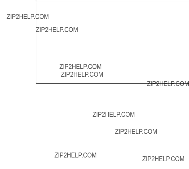
The definition of a font with a quantity n characters would appear as shown below.
Table
Font ID Command
Font Header
Character Code1
Character Descriptor1
Character Data1
Character Code2
Character Descriptor2
Character Data2
M
Character Coden
Character Descriptorn
Character Datan

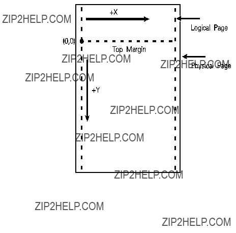
Coordinate System
Both bitmap and scalable characters are designed in an area referred to as a cell or window, and each has its own coordinate system and set of units.
Bitmap Fonts
Characters of a bitmap font are designed within a rectangular area referred to as a cell. The bitmap character cell is illustrated in Figure
Intellifont Scalable Fonts
Characters of an Intellifont scalable font are designed within a rectangular area known as the Agfa Design Window (Figure

The master font design size is 250 points (a CG point=.01383 inches). There are 8782 units per Em at the Master Font Size.
Figure
TrueType Scalable Fonts
TrueType scalable font character coordinates are typically based on a system of 2048 units per Em. The baseline is defined by

Font Header Command
The Font Header command is used to download font header data to the printer.
EC ) s # W [font header data]
The value field (#) identifies the number of bytes in the font header. The font header fields are described under Font Header Format, later in this chapter.
Font Header Format
The font header describes those characteristics of a font which are common to all its characters. Five font headers are included here:
zFormat 0 Font Header for PCL Bitmapped Fonts - This font header, shown in Table
zFormat 20 Font Header for
zFormat 10 Font Header for Intellifont Bound Scalable Fonts - For creating Intellifont scalable fonts which are restricted (bound) to a single symbol set. This font header is shown in .
zFormat 11 Font Header for Intellifont Unbound Scalable Fonts - For creating Intellifont scalable fonts which are not bound to a single symbol set, but are instead composed of a range of compatible symbol collections. This font header is shown in .
zFormat 15 TrueType Scalable Font Header - This new font header supports TrueType scalable fonts (bound or unbound). This font header is shown in Table

Note
Notes
Use the Font ID command to designate a unique ID number prior to the download of a font header. If an existing font is already associated with this ID, the existing font is deleted upon the download of the font header. Unless otherwise specified, inappropriate values in a font header field invalidates the font download process; a font is not created and the associated font data is discarded.
Intellifont scalable font formatting also requires the Intellifont Scalable Typeface Format document, which supplements the information provided here. For information on how to obtain this document, refer to ???Related Documents??? in the front of this manual.
The figures that follow illustrate the font header formats for the various font classifications. The individual fields for the font headers are described following the figures.
Although some LaserJet printer models do not use all of the data in the font header and thus ignore many of the fields, a font creator should use valid values in all of the font header fields. This ensures font compatibility across the LaserJet printer family and with future printers, which may use these fields.
Those font header fields identified as ???reserved??? should be set to zero.
Table
Table
Table
Bitmapped) (continued)
Table
Scalable)
Table
Table
Table
Scalable Fonts) (continued)
Table
Scalable Fonts) (continued)
Table
Fonts)
Table
Data Types
In the font header and character descriptor information that follows, the abbreviations shown below are used to define the data type of each field:
Table

Table
Font Descriptor Size (UI)
Specifies the number of bytes in the font descriptor. See the font header figure for the appropriate font descriptor size.
Header Format (UB)
The Header Format byte identifies the font to format (see below).
Table
Font Type (UB)
Font type describes the font???s relation to symbol sets.
Table
0Bound font. Character codes 32 to 127 [decimal] are printable.
1Bound font. Character codes 32 to 127 [decimal] and 160 to 255 [decimal] are printable.

Table
2Bound font. All character codes 0 to 255 are printable, except 0, 7 to 15, and 27 [decimal] (see note below).
10Unbound font. Character codes correspond to HP MSL numbers (for Intellifont unbound scalable fonts).
11Unbound font. Character codes correspond to Unicode numbers (for TrueType unbound scalable fonts).
Style MSB (UI)
The Style MSB (byte 4) is combined with the Style LSB (byte 23) to make the style word. The contents of the style word are described below. The Style word (decimal) is calculated using the formula:
Style Word = Posture + (4 x Width) + (32 x Structure)
The binary structure of the Style word is shown below.
Table
Table

Example
Assuming a font style of ???italic compressed contour??? is desired, the value (#) would be:
1 + (2??4) + (3??32) = 105
Baseline Position (UI)
Bitmap Font - Specifies the distance from the top of the cell to the baseline. The baseline is the dot row on which all of the characters in a given line appear to stand (see ). The measurement of this distance is in font resolution dots, as defined in the Resolution Field of a Format 20 font header (default=300 dpi).
Intellifont Scalable - Specifies a
TrueType Scalable - Baseline Position must be set to zero.
Cell Width (UI)
Specifies the width of the cell. The cell must be wide enough to accept the widest character. The cell width range is 1 to 65535.
Bitmap Font - Specified in PCL coordinate system dots.
Scalable Font - Specified in design units.
Cell Height (UI)
Specifies the height of the cell. The design cell for a font must be tall enough to accept the tallest character and greatest descender. The legal range is 1 to 65535.
Bitmap Font - Specified in PCL coordinate system dots.
Scalable Font - Specified in design units.
Figure
Orientation (UB)
Specifies the orientation of the font. All characters within the font must have the same orientation as those specified in the font header; otherwise they are discarded as they are downloaded.
0 = portrait (0 degrees; the orientation of the raster scan of the printer)
1 = landscape (90 degrees counterclockwise)
2 = reverse portrait (180 degrees counterclockwise)
3 = reverse landscape (270 degrees counterclockwise)

Spacing (B)
Specifies the spacing of the font. A value of zero (0) specifies fixed spacing and one (1) specifies proportional spacing.
Symbol Set (UI)
Specifies the symbol set for the font. This value is computed by taking the value of the value field for the symbol set, multiplying it by 32, adding the decimal (ASCII) value of the termination character (the symbol set ID character value) of the escape sequence, and subtracting 64.
For example, to compute the value for the ASCII
0U = (0??32) +
The legal range of symbol set escape sequence field values is 0 to 2047. Refer to Appendix C in the PCL 5 Comparison Guide for the HP defined symbol set values for use in the font header.
HP reserves the right to define the symbol set escape sequence value field values of 0 to 1023. Symbol set escape sequence value field values 1024 to 2047 are available for use by independent font vendors.
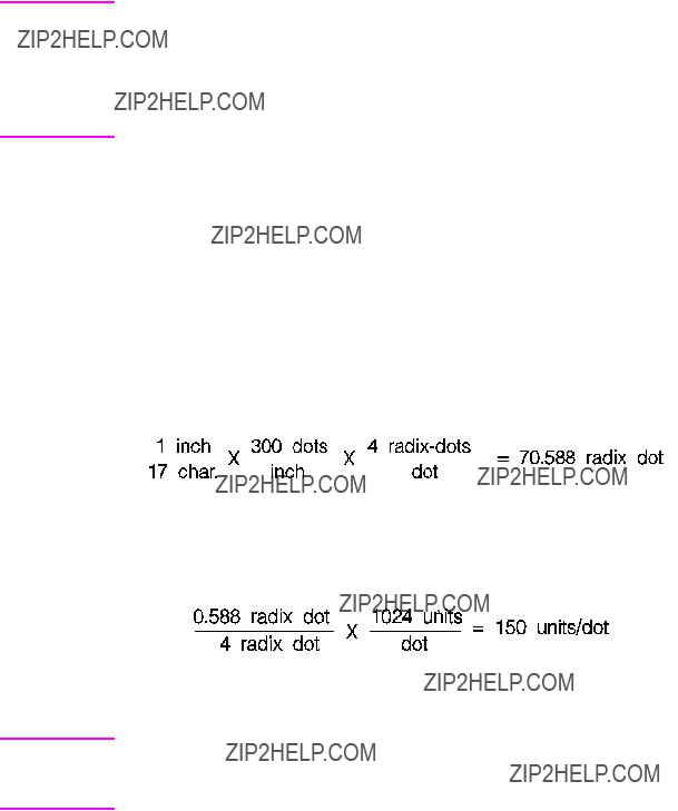
Notes
Note
EN
Symbol set escape sequence termination characters can be any upper case ASCII character ???A??? through ???Z.??? ???Q??? is reserved for use with HP ???Specials??? symbol sets and is not recommended for general use.
Symbol set ID???s of ???@??? and ???X??? do not have a corresponding Symbol Set selection command, sets marked as such can be selected only with the Font ID.
This field must have a value of 56 for a type 10 or 11 font (unbound Intellifont scalable) to be valid.
Pitch (UI)
Bitmap Font - Specifies the pitch of the font in quarter dots (four
For example, a a 17 cpi font designed at 300 dpi has a pitch value of 70 radix dots as calculated:
The remainder 0.588 is converted back to dots and then to
Pitch Extended is set to 150
For a proportional font, the width ???printed??? for a control code Space is determined by the pitch value, unless an HMI command is received following the selection of the font.
Scalable Fonts - Contains the master design space width (escapement) of the font in design units.
Font Header Format

Height (UI)
Bitmap Font - Specifies the design height of the font in
characteristic value of the font. A PCL point is 1 (0.01389) inch.
72
It combines with Height Extended to specify the design height of the font in
For example, a 10 point font at 300 dpi has a height of 166
as calculated:
72
The remainder 0.667 is converted back to dots and then to
Intellifont Scalable - Specifies the master design height of the font in
TrueType Scalable - Set the Height field to zero.
xHeight (UI)
Bitmap Font - Specifies the height of the lower case ???x??? in
Scalable Fonts - Specifies the distance from the baseline to the lower case ???x??? height in design units.
Width Type (SB)
Specifies the proportionate width of characters in the font.
Style LSB (UB)
The least significant byte (LSB) of the Style word. Refer to Style MSB for a description of the Style word.
Stroke Weight (SB)
Specifies the thickness of the strokes used in designing the font. The supported stroke weight values are
Table
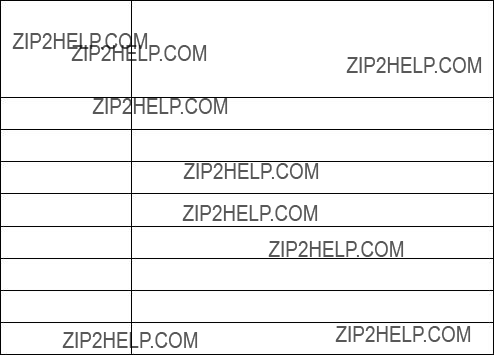
Table
0Medium, Book, or Text
1Semi Bold
2Demi Bold
3Bold
4Extra Bold
5Black
6Extra Black
7Ultra Black
Typeface (UB)
This field specifies the HP typeface number of the font. The current version of this field, supported by the &payette; printer, is described first. Then a previous field, supported in earlier printers, is described.
Current Usage
In the LaserJet 4 printer version of this field, an unsigned short integer is assembled from the two unsigned bytes of data. Printers, when seeking to match a typeface request with available font resources, may treat the typeface number as a single value. If an exact match cannot be made, the request may be ignored (for selection purposes, however, the font select table is updated).
The procedure for allocating typeface numbers for the font products of various vendors, however, will consider the typeface number to be composed of two distinct fields: a vendor field (consisting of the four most significant bits) and a typeface family field (consisting of the 12 least significant bits). The following diagram illustrates this scheme:

Vendor Number - Bits 15 - 12. This value is assigned by HP and is between decimal values 0 and 15.
Typeface Family Number - Bits 11 - 0 This value is between 0 and 4095. See Appendix C in the PCL 5 Comparison Guide.
Typeface Family Values are calculated according to the following formula:
Example
The HP typeface number for Agfa Dom Casual typeface is 4157 (vendor value=1, and typeface value=61):
61 + (1 ?? 4096) = 4157
Previous Usage
The previous treatment of the Typeface field supported the LaserJet IIP, IID and LaserJet III family printers. It consisted of the Typeface Least Significant Byte (LSB; the original,
The previous typeface family value field is shown below. It included a
Table
Table

Serif Style (UB)
Specifies one of the following defined serif styles.
Serif Style values

Table
11Script Calligraphic
12Script Broken Letter
Values for bits 6 & 7
Quality (UB)
This field specifies the quality of the font.
Table
Value Quality
0Data processing (draft)
1Near Letter Quality
2Letter Quality
Placement (SB)
Placement specifies the position of character patterns relative to the baseline.
Bitmap Font - The placement values for bitmap fonts are listed in the following table.
Table
Scalable Font - Set the Placement field to zero.
Underline Position (Distance) (SB)
Bitmap Font - Specifies the distance from the baseline to the top dot row of the underline in font design dots. Zero specifies an underline position at the baseline. A positive value specifies an underline position above the baseline. A negative value specifies an underline position below the baseline.
Scalable Font - Set Underline Position to zero. The Master Underline Position field (see below) identifies this information for scalable fonts.
Underline Thickness (UB)
Specifies the thickness of the underline in font design dots for a bitmap font.
Bitmap Font - A bitmap font prints
Scalable Font - Set Underline Thickness to zero. The Master Underline Thickness field (see below) identifies this information for scalable fonts.
Text Height (UI)
Specifies the font???s optimum
Bitmap Font - Specified in
Scalable Fonts - Specified in design units.
Text Width (UI)
Specifies the font???s average lowercase character width. (This average width may be weighted on the basis of relative frequency.)
Bitmap Font - Specified in
Scalable Font - Specified in design units.
First Code (UI)
First Code specifies the character code of the first printable character in the font. This value is between 0 and 255 inclusive. The Space Character may be printable and will print an image if one is defined, otherwise a Space control code is executed. Currently, PCL 5 LaserJet printers use the Font Type field to determine the first and last codes of the symbol set, as shown below:
Table
Last Code / Number of Characters (UI)
Bound Font: Specifies the last code in the font. This value may be greater than the last code of the symbol set as implied by the font type because there may be components of compound characters that are not part of the symbol set but must be downloaded. The printable codes are implied by the font type (refer to first code described above).
Unbound Font: For an unbound font (type 10 or 11), this field specifies the maximum number of characters that can be down- loaded into the font.
Pitch Extended (UB)
Bitmap Font - This is an addition to the Pitch field which extends the pitch an extra eight bits. The value of this field is in font design units. For example, a 17 pitch font designed at 300 dpi has a Pitch field of 70 (17.5 dots, or 17.1429 cpi) and a Pitch Extended field of 150 (0.1465 dots additional, which adds to 17.6465 dots, or 17.0005 pitch).
An example for calculating the Pitch and Pitch Extended fields is provided in the Pitch field description, above.

Scalable Font - Set Pitch Extended field to zero.
Height Extended (UB)
Bitmap Font - This is an addition to the Height field which extends the height an extra eight bits. The value of this field is in font design units. For example, a 10 point font designed at 300 dpi would have a Height field of 166 (41.5 dots, or 9.96 points) and a Height Extended field of 170 (0.1660 dots additional, which adds to 9.9998 points).
This field is calculated similar to the Pitch Extended field. Refer to the Pitch description, above.
Scalable Font - Set The Height Extended field to zero.
Cap Height (UI)
Cap Height is a percentage of the Em of the font and is used to calculate the distance from the capline (top of an unaccented, uppercase letter, such as an ???H???) to the baseline.
Bitmap Font - Fonts containing a 0 in this field are assumed to have a cap height percentage of 70.87% of Em (Em being a measure, in points, of the height of the body of the font.
The Cap Height data is represented as the product of the cap height percentage and the maximum unsigned integer:
0.7087 ?? 65535 = 46,445
For
Scalable Font - Contains the cap height in design units.
Font Number (ULI)
The Font Number field uses four bytes (byte 44, 45, 46, and 47). The lower three bytes (45, 46, and 47) contain the font number in hexadecimal. This is the number the vendor assigns to their typeface. The most significant byte (byte 44) consists of a flag in the most significant bit indicating whether the font is in its native (0) format or has been converted (1) from another format. The remaining lower seven bits contain the ASCII decimal value for the first initial of the font vendor???s name (this is assigned by
Table
For example, the number that Agfa assigns for a CG Times Bold Italic, native format, font is 92505. This number is converted to hexadecimal and used for the lower three bytes of the Font Number. Bit 8 of byte 44 is 0, since the native format is used and the lower seven bits are the ASCII value for ???C??? (C for Compugraphic; 0100 0011). This process is summarized below.

Figure
This field is ignored by the printer for bitmap fonts.
Font Name (ASC16)
This is a 16 character ASCII field to which you may assign a font name. The font name is used in the Typeface List (or Font List printout), under Name or Typeface (if the printer does not have a name string assigned to the typeface family code in its font selection table).
X Resolution (UI)
The X Resolution field is the pixel resolution in the X scan direction at which the font was designed.

Note
Note
Y Resolution (UI)
The Y Resolution field is the pixel resolution in the Y scan direction at which the font was designed.
This field is not present in the Format 15 Font Header and is not necessary for TrueType fonts.
Scale Factor (UI)
The Scale Factor field indicates the number of design units per Em, and is the unit used for all scalable metrics in the font header. It is used for TrueType and Intellifont scalable soft fonts.
Master Underline Position (SI)
The Master Underline Position is the top of the PCL floating underline with respect to the baseline in design units.
For scalable fonts, the Master Underline Position field replaces the
Master Underline Thickness (Height) (UI)
The Master Underline Thickness field defines thickness of the floating underline in design units.
Font Scaling Technology (UB)
For scalable fonts, this field species the technology to be used for font scaling.
Table
0Intellifont
1TrueType

Variety (UB)
The interpretation of this field depends on the value of the preceding (Font Scaling Technology) byte. For TrueType fonts, this field must be set to zero.
OR Threshold (UI)
Formerly called the ???LRE Threshold,??? this is the pixel size in design units above which the missing pixel recovery process is switched on in Intellifont scaling and rasterization.
Global Italic Angle (SI)
The Global Italic Angle field contains the tangent of the italic angle times 215 (relative to the vertical). Set this field to zero for upright fonts. For detailed information on Global Italic Angle, refer to Intellifont
Scalable Typeface Format.
Global Intellifont Data Size (UI)
The Global Intellifont Data Size identifies the size of the Global Intellifont data block. For detailed information about Global Intellifont
Data Size, refer to Intellifont Scalable Typeface Format.
Global Intellifont Data
For detailed information on Global Intellifont Data refer to Intellifont Scalable Typeface Format.
Character Complement (Array of UB)
This

Individually defined bits are shown in the following two tables:
Table
Table
There are no invalid Character Complement field values. Examples of values for the field include:
Table
Note
Note
EN
Table
??????ffffffff5ffffffe?????? Font indexed in Unicode and is compatible only with East Europe Latin character sets.
Checksum
The Checksum field is over bytes 64 through the end of the header. The checksum should contain a value which, when added to the sum of byte 64 through the reserved byte, equals a value which, when divided by 256 (modulo 256 arithmetic), results in a remainder of 0. For example, if the sum = 10,234 then, 10,234 mod 256 = 250. Therefore, the checksum should = 6 (since 250+6 = 256 which would produce 0 [mod 256]).
In the Format 15 Font Header for TrueType Scalable Fonts, this field is located at the end of the Segmented Font Data section immediately following the descriptor data. See ???Segmented Font Data??? later in this chapter.
Copyright
This field contains ASCII data and is optional.
In the Format 15 Font Header for TrueType Scalable Fonts, this field is located in the Segmented Font Data section immediately following the descriptor data. See ???Segmented Font Data??? later in this chapter.
Segmented Font Data (Format 15)
The Segmented Font Data section immediately follows the main body of a Format 15 Header for TrueType Scalable Fonts. Each segment contains three parts: a Segment Identifier, Segment Size, and Data
Segment.
The Segmented Font Data section is terminated by the Null Segment. (In the deviant case where no Null Segment is encountered prior to the end of the font header &emdash; as defined in the Font Header command &emdash; the font is invalidated. A font also is invalidated in the event that a Null Segment is encountered too soon.)
Font Header Format

Table
Table
x = Font Descriptor Size.
# = Font header length (as defined in Font Header command).
Segment Identifier (UI)
Each entry in the Segmented Font Data Section has its own unique identification number. The following values are defined:
Table
Data segments with an unrecognized identifier are ignored.
Segment Size (UI)
For each entry in the Segmented Font Data section, the Segment Size indicates the number of bytes in the immediately following Data Segment. The size for the Null Segment is 0.
Formats of Data Segments
AP (Application Support Segment) The definition of this segment is reserved.
CC (Character Complement) This field has the same form (i.e., 8 unsigned bytes) and function as does the Character Complement of Format 11 fonts. The Character Complement field should be present with type 10 and 11 (unbound) fonts, but has no role to play in type 0, 1 and 2 (bound) fonts.
CP, copyright This field will consist of ASCII data and is optional.
GI (Global Intellifont Data) Reserved for future use.
GT (Global TrueType Data) This data segment contains first a Table Directory, then five or more tables used by the TrueType font scaler. Every TrueType font needs to have this segment.
The Table Directory is patterned after the initial segment of the TrueType font file as described in True Type Font Files. The Table Directory has a
The Global TrueType Data for every TrueType font entity must contain a head, hhea, hmtx and maxp table.
Another required table is the gdir table. When the font header is downloaded, the gdir table should have a size of 0 and an offset of 0. The gdir table is then built in RAM to accommodate the maximum number of glyphs to be downloaded to the given font ??? with 2 or 4 bytes of offset and 2 bytes of length per glyph. This maximum number of glyphs is obtained from the numGlyphs field of the maxp table. Entries in the gdir table are filled in by the TrueType rasterizer as characters are downloaded.
The optional cvt, fpgm and prep tables, as defined in True Type Font Files, typically appear in the Global TrueType Data Segments of hinted TrueType soft fonts, but should not appear in unhinted fonts.
IF (Intellifont Face Data) Reserved for future use.
PA (PANOSE Description) This data segment of variable length may be used for the purpose of font selection and substitution. Its definition continues to evolve. A
in True Type Font Files.
PF
XW
Checksum
The value of this byte, when added to the sum of all of the bytes from byte 64 of the descriptor through the Reserved byte, should equal 0 in modulo 256 arithmetic.
Font Header Examples
Two examples for downloading a Font Header are provided below; one for a bitmap font and one for an Intellifont scalable font.
Bitmap Example
To download a bitmap font header for a portrait HP
EC*c1D (set Font ID to 1)
EC)s#W (# = 64 bytes of font descriptor data + x bytes of optional data)
An example of the bitmap header is shown on the following page.
Table

Table
....Copyright Statement .... (optional) }= x bytes added to header data
....Application Support ....(optional) }= x bytes added to header data
Intellifont Scalable Example
To download an Intellifont scalable header for an HP
EC*c1D (set Font ID to 1)
EC)s#W (# = 80 bytes of font descriptor data + x bytes of Global Intellifont data + x bytes of optional data)
Table
Table
Table

Character Definitions
Character Code Command
The Character Code command establishes the decimal code that is associated with the next character downloaded. This value is used to reference the character for printing.
EC * c # E
For TrueType fonts, a special code must be used to download glyphs which never stand alone as characters. FFFF (hex) should be used for this purpose.
Example
To designate the character code for an ASCII
EC*c112E

Character Definition Command
The Character Descriptor and Data command is used to download character data blocks to the printer for both bitmap and scalable fonts.
EC ( s # W [character descriptor and data]

Character Descriptor Formats
Character definition formats for PCL Bitmap, Intellifont Scalable and TrueType Scalable fonts are shown on the following pages.
Table
Character Descriptor and Data Format for PCL Bitmap Fonts
The descriptor of a PCL bitmap character is at least 14 bytes long and contains information such as the character???s width and height.
The character data is binary (raster) data that identifies the shape of the character.
Table
Table
and Data Format
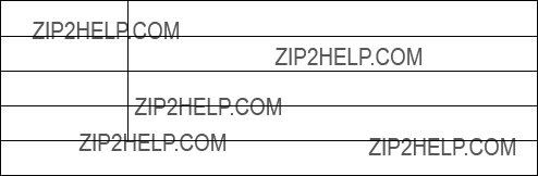
Table
Table
Data Format
Format (UB)
This is the first byte of every character data block header. It specifies the format of the character descriptor and data. The format number used for bitmap fonts is 4. This format must match that of the Font Header.
Table
Value Format
10* Intellifont Scalable
15* TrueType Scalable
* These are described later in this chapter.
If the format number is different from that expected by the device, the character is discarded.

Continuation (B)
This is the second (and last) byte of every character data block header. It specifies whether the following data is the first (0) data block of a new character definition, or a continuation (1) block for a character definition which has already been received by the printer. Because the value field in a Character Definition command is limited to 32767 bytes, characters whose byte count exceed this must be sent in two or more blocks.
Descriptor Size (UB)
This is the first byte of the character descriptor. It specifies the size of the character descriptor in bytes. The descriptor size used by the HP LaserJet printer family for bitmap fonts is 14.
Class (UB)
Specifies the format of the character data. For bitmap fonts only values 1 and 2 are used, as described below.
Table
Value Class
1Bitmap
2Compressed Bitmap
* These are described later in this chapter.
Class 1 - Bitmap Data
Class 1 or bitmap (raster) character data is a string of bytes containing the
The number of bytes of the character data should be exactly Character Width (in bytes) times Character Height. If more
data is received, it is discarded; if less data is received, the character consists of only the data downloaded.
Class 2 - Compressed Bitmap Data
For a compressed bitmap character, the data is composed of a string of bytes using a
The width of each row is determined by the character width (in dots) as specified in the character descriptor for the character. The pixel count (number of 1???s and 0???s bits) for each row in the character cell must equal the character width. For example, in Figure
Once the row has been filled, the row is duplicated as indicated in its first byte, then a new row is started.

Figure

Orientation (UB)
Orientation byte specifies the orientation of the character. The orientation of the character must match the orientation of the font.
Table
Value Orientation
0Portrait
1Landscape
2Reverse portrait
3Reverse landscape
If the orientation is not supported or is different from the orientation specified in the font header, the character is discarded.
Left Offset (SI)
Left offset specifies the distance in dots from the reference point to the left side of the character pattern on the physical page coordinate system (this value is orientation dependent). The left and top offsets locate the character reference point about the cursor position (see Figure
PCL 5 printers support kerning (both negative left and right side bearings) of both
The legal range for the left offset is
Top Offset (SI)
Top offset specifies the distance in dots from the reference point to the top of the character pattern on the physical coordinate system (this value is orientation dependent.) The left and top offsets locate the character reference point about the cursor position (see Figure
Character Width (UI)
The Character Width, used for bitmap fonts only, identifies the width of the character in dots on the physical coordinate system. Generally, this width is from the farthest left black dot to the farthest right black dot. Character width is orientation dependent.
The legal range for character width is 1 to 16384 dots.
Character Height (UI)
Character Height specifies the height of the character in dots on the physical coordinate system. Character height is orientation dependent.
The legal range for character height is 1 to 16384 dots.
Delta X (SI)
Delta X specifies the number of quarter dots (radix dots) by which the horizontal position within the logical page coordinate system is incremented after printing the character. This value is only used by the printer when the font is proportionally spaced.
The legal range for delta X is
Character Data
Character data is a string of bytes containing the

Figure
Figure
Character Descriptor and Data Format for Intellifont Scalable Fonts
The character header contains a block of bytes that identify character outline data. Table
.
Table
Data Format
1.Continuation is supported for classes 1, 2, 3 and 15 only.
2.These bytes appear only on the last continuation.
Table

Table
Contour Tree Data
M
XY Coordinate Data
M
Table
Continuation Block
1.Continuation is supported for Intellifont scalable fonts for class 3 only.
2.This byte appears only on the last continuation.
Table
and Data Format

Format (UB)
This is the first byte of every character data block header. It specifies the format of the character descriptor and data. The format number for Intellifont scalable fonts is 10.
Table
Value Format
4* LaserJet Family (Raster)
10 Intellifont Scalable
15* TrueType Scalable
* These are described elsewhere in this chapter.
If the format number is different from that expected by the device, the character is discarded.
Continuation (B)
This is the second (and last) byte of every character data block header. It specifies whether the following data is the first (0) data block of a new character definition, or a continuation (1) block for a character definition which has already been received by the printer. Because the value field in a Character Definition command is limited to 32767 bytes, characters whose byte count exceed this must be sent in two or more blocks. Table
Descriptor Size (UB)
This is the first byte of the character descriptor. It specifies the size of the character descriptor in bytes. The typical descriptor size for Intellifont scalable fonts is 2.
Class (UB)
Specifies the format of the character data. For Intellifont scalable fonts values 3 and 4 are used, as described below.

Table
3Contour (Intellifont Scalable)
4Compound Contour (Intellifont Scalable) 15* TrueType Scalable
*These are described elsewhere in this chapter.
Class 3
Class 3 is for Intellifont scalable contour character data. The contour character data is organized as described in Table
Class 4 - Intellifont Scalable Compound Character
Data
A class 4 character is a compound character and composition data follows. The composition data is organized as described in Table
Contour Data Size (UI)
The size of the contour data including the size of this field. For a detailed description of this field, refer to Intellifont Scalable Typeface
Format.
Metric Data Offset (SI)
The offset to the Metric Data relative to the address of the Contour Data Size field.

Character Intellifont Data Offset (SI)
The offset to the Character Intellifont Data relative to the address of the Contour Data Size field.
Contour Tree Offset (SI)
The offset to the contour Tree Data relative to the address of the Contour Data Size field.
XY Data Offset (SI)
The offset to the XY data relative to the address of the Contour Data Size field.
Metric Data
For information about Metric Data refer to the Intellifont Scalable Typeface Format document.
Character Intellifont Scalable Data
For information about Character Intellifont Scalable Data, refer to
Intellifont Scalable Typeface Format.
Contour Tree Data
For information about Contour Tree Data, refer to Intellifont Scalable Typeface Format.
XY Coordinate Data
For information about XY Coordinate Data, refer to Intellifont Scalable Typeface Format.
Checksum
This is a checksum of all the contour character data. The checksum value is contained only in the last character data block.

Compound Character Escapement (SI)
The escapement in design units of a compound character.
Number of Components (UB)
The number of components of a compound character.
Component List
This is a list of component descriptions. The list contains Number of Components elements. Each component descriptor consists of 6 bytes as described in Table
Character Descriptor and Data Format for
TrueType Fonts
Table
Table

Table
Table
# = Character data block size as defined in Character Definition command.
Format (UB)
This is the first byte of every character data block header. It specifies the format for character downloading. The number 15 designates the TrueType character format.
Table
15TrueType Scalable
*These are described elsewhere in this chapter.

Continuation (B)
This is the second (and last) byte of every character data block header. It specifies whether the following data is the first (0) data block of a new character definition, or a continuation (1) block for a character definition which has already been received by the printer. Because the value field in a Character Definition command is limited to 32767 bytes, characters whose byte count exceed this must be sent in two or more blocks.
Descriptor Size (UB)
This is the first byte of the character descriptor. It specifies the size of the character descriptor in bytes. The character descriptor includes everything that is both after the continuation byte and prior to the Character Data Size field. The TrueType character descriptor includes this Descriptor Size byte plus the following Class byte. The minimum value for Descriptor Size is therefore 2. (Additional descriptor information, if any, can be added immediately after the Class byte.)
Class (UB)
This field is used to distinguish different character data types within a given character format. (For instance, among Intellifont characters of format 10, the Class byte is used to distinguish compound characters from simple Intellifont contour characters.) All TrueType scalable characters are handed to the TrueType font scaler in the same format, consequently, the Class byte does not provide vital new information. For TrueType, set the Class value to 15.
Table
15TrueType Scalable
*These are described elsewhere in this chapter.
Character Data Size (UI)
The value of the Character Data Size should equal the sum of the sizes of the Character Data Size, Glyph ID, and TrueType Glyph Data fields. This value alerts the PCL interpreter when a continuation block is needed. The minimum possible value is 4. The value of Character Data Size plus Descriptor Size plus 4 (for the Format, Continuation, Reserved and Checksum bytes) will never be less than the value # given in the character download command. If the sum is exactly equal to #, then no continuation block is to be expected for the given character. However, if the sum exceeds #, then a continuation block is needed. A condition for the validity of a downloaded scalable TrueType character is that the sum of the # values for all of that character???s data blocks equals the sum of the Descriptor Size and Character Data Size and 2 (for Reserved and Checksum), plus 2 times the number of character data blocks (for Format and Continuation bytes).
Glyph ID (UI)
This field is used by the TrueType font scaler as an ID number for the glyph data associated with the given character.
TrueType Glyph Data
This field contains the data segment associated with the given character as found in the glyf table of the original TrueType font file. See the description in True Type Font Files.
Checksum (UB)
The value of this byte, when added to the sum of all of the bytes in the Character Data Size, Glyph ID, and TrueType Glyph Data fields, should equal 0 in modulo 256 arithmetic. The Checksum is found only in the last character data block associated with a given character.

Character Definition Examples
Table
Table
Table
Bitmap Landscape Character Example
To download the character descriptor and data for a landscape, 10 pitch, 12 point, upright, medium, Courier
EC*c112E (112 is the decimal character code for an ASCII
EC(s120W [character descriptor and data]
Table
Table
Table

12 Macros
Attention: Product Specials 11311 Chinden Blvd. Boise, ID 83714
(208)
Macro Creation
Designate a unique identification (ID) number prior to the definition of a macro using the Macro ID command. This number is assigned to the macro. If a macro is already associated with this ID number, the previously existing macro is deleted from user memory during the definition of the new macro. Subsequent macro operations are accomplished using the macro ID number.
A macro is created in the printer in several steps. First, the start macro command is sent to the printer to indicate the start of a macro definition. Next, the printer commands, control codes, and data that constitute the macro are sent to the printer, in the intended order of their execution. Finally, the End Macro command is sent to the printer to indicate the end of the macro definition
Table
To invoke a macro, send the Macro ID command with the ID number of the macro, then send the Macro Control command with a value field of 2, 3, or 4 (EC&f2X, EC&f3X, or EC&f4X). This performs the macro in the specified mode: Execute (value field=2), Call (value field=3), or Overlay (value field=4). Refer to the following section ???Macro Invocation??? for a description of these modes.

Macros occupy a portion of user memory. The number of macros that can be stored simultaneously in user memory is limited only by the amount of available user memory.
Macro Invocation
The overlay environment consists of the current settings for the following features with the remainder of the environmental features set to their user default values:
saved when a macro is called, nor is it restored upon completion. The Push/Pop Cursor Position command can be used to save and recall a cursor position.
Temporary / Permanent Macros
During its definition, a macro is automatically designated as temporary. A temporary macro is deleted from user memory during a printer reset. A macro can be designated as permanent to prevent the printer from deleting it during a printer reset. A macro is designated as temporary or permanent by reference to its ID number, using the Macro Control command described later in this chapter.
Deleting Macros
There are several mechanisms provided by PCL macro control for explicit deletion of macros from user memory. These include commands to delete all macros, all temporary macros, or an individual macro by reference to its macro ID number, using the Macro Control command described later in this chapter.
Both temporary and permanent macros are deleted from memory whenever the printer???s power is turned off.
Macro ID
The Macro ID command specifies an ID number for use in subsequent macro commands.
EC & f # Y
#=Macro ID number
This number is used in subsequent macro operations.
The factory default macro ID is 0.
Example
To establish a macro ID number of 5, send:
EC & f 5 Y

Macro Control
The macro control command provides mechanisms for definition, invocation, and deletion of macros.
EC & f # X
Other than call and execute, no macro control operations may occur within a macro.
A printer reset command (ECE or UEL) is not allowed in a macro.
HP LaserJet printers. Refer to the ???PCL Feature Support Matrix??? in Chapter 1 of the &cguide; for specifics.
PCL macro control commands are not allowed while in
Macros can be supplied in ROM (read only memory), such as custom macro cartridges or on SIMM modules. The following considerations apply to all
z
zThe ID numbers for
zIn case of conflicting ID numbers in
1Cartridge macros. (In printers that have two cartridge slots, one cartridge has priority over the other. This priority depends on the printer. Refer to Appendix E of the PCL 5 Comparison Guide for the macro cartridge priority.)
2SIMM macros. SIMM 1=highest, then SIMM 2, etc.
Example
To define a macro with an ID of 7, send:
EC&f7y0X
z
z
z
escape sequences, control codes, and data
z
z
z
To stop the macro definition, send:
EC&f1X
To make the macro with an ID of 7 permanent, send:
EC&f7y10X
To enable the macro with an ID of 7 for automatic overlay, send:
EC&f7y4X
To delete the macro with an ID of 7, send:
EC&f7y8X
Macro Control Example
The following illustrates the definition of a letterhead macro.
Table
Table
This macro now can be executed, called, or enabled for automatic overlay.

13 The PCL Print Model
Introduction
The Print Model feature allows images and characters to be filled with any of the printer???s predefined shading or
Print model operation defines a pattern, source image, and destination image. These images are applied to each other using the print model???s transparent and opaque modes to produce a resulting image that is a combination of the others. The print model features, listed below, are illustrated in Figure
zPattern
zSource Image
zDestination Image
zSource Transparency Mode
zPattern Transparency Mode
Figure

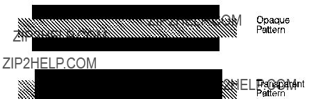
Pattern Transparency Mode
The transparency or opaqueness of the white pixels in the pattern. When set to 0 (transparent), these pixels have no effect on the destination; when set to 1 (opaque), they are applied through the black pixels of the source pattern to the destination.
Figure
Figure
In the first example (1a), the transparency mode for both the source image and the pattern is transparent. Since the source mode is ???transparent,??? only the
In the second example (1b), the source mode is still ???transparent,??? but the pattern mode is ???opaque??? ??? so the pattern???s white pixels are applied to the destination. The resulting image shows the entire circle region visible and patterned.
In the third example (1c), the source mode is ???opaque??? and the pattern mode is transparent. Since the source mode is opaque, the entire source image (the circle and the surrounding square) appears overlaid onto the destination. The pattern, however, is allowed to pour through only onto the
In the fourth example (1d), both source and pattern modes are ???opaque.??? The entire source image is overlaid onto the destination, and the entire circle is patterned.
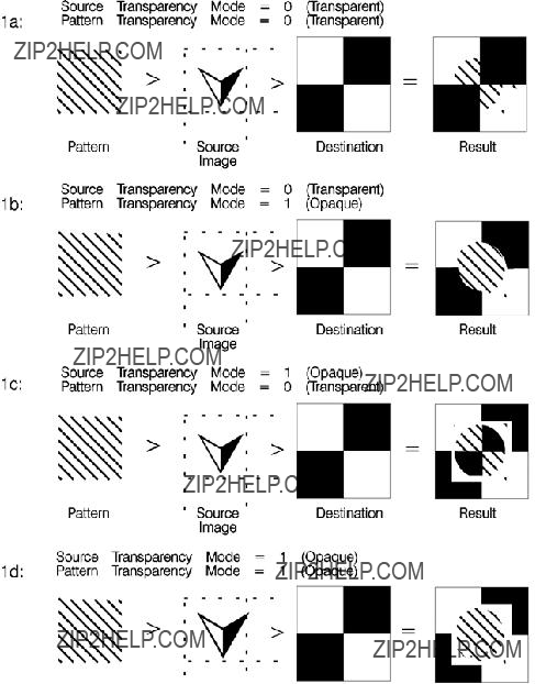
Figure
Command Sequence
The following illustration shows the Print Model Command Sequence for selecting a current pattern and using it to fill a destination image.
Table

Table
???
???
End of Page Data
Source Transparency Mode Command
The Select Source Transparency Mode command sets the source image???s transparency mode to transparent or opaque.
EC * v # N
#=0 - Transparent 1 - Opaque
With a transparency mode of ???0??? (transparent), the white regions of the source image are not be copied onto the destination. With a transparency mode of ???1??? (opaque), the white pixels in the source are applied directly onto the destination.
Refer to the preceding definitions and the discussion of Figure

Pattern Transparency Mode Command
The Pattern Transparency Mode command sets the pattern???s transparency mode to transparent or opaque.
EC * v # O
#=0 - Transparent 1 - Opaque
A transparency mode of ???0??? (transparent) means that the white regions of the pattern image are not copied onto the destination. A transparency mode of ???1??? (opaque) means that the white pixels in the pattern are applied directly onto the destination.

Pattern ID (Area Fill ID) Command
The Pattern ID command (formerly called Area Fill ID) identifies the specific shading,
PCL Rectangular Area Fill Graphics.)
EC * c # G
Table
Selecting
# = ID number of
1.Not supported on all LaserJet family printers. Refer to the ???PCL Feature Support Matrix??? in Chapter 1 of the PCL 5 Comparison Guide for specifics.
#=ID number of
For rectangular areas, the pattern material is determined by both the pattern ID and the value of the Fill Rectangular Area command. For other images, the pattern material is determined by the pattern ID and the value of the Select Pattern command.
Figure

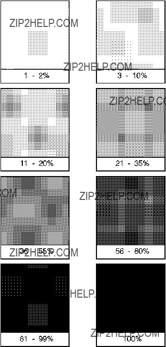
Figure

Figure

Select Current Pattern Command
The Select Current Pattern command identifies the type of pattern to be applied onto the destination.
EC * v # T
#=0 - Solid black (default) 1 - Solid white
2 - Shading pattern
3 -
4 -
This command selects which type of pattern is applied. For values 2, 3, and 4, the shading level (Figure

In addition to the eight shading patterns and six
z
zSet Pattern Reference Point EC*p#R
zPattern Control EC*p#Q <Unknown> <list> >
To create a user pattern, a user defines a binary raster data image as a base pattern. This base pattern is downloaded to the printer using the
To apply the pattern to an image, the printer duplicates or tiles (like placing ceramic tiles) the pattern across and down the page. This pattern can be applied to any image, or used as rectangular area fill.
Figure
A

Figure
Pattern Reference Point
The pattern reference point is a position on the logical page at which the base pattern is positioned for tiling. The upper left corner of the base pattern is positioned at this point (see ). The default pattern reference point is position 0,0. However, it is possible to set the pattern reference point to the current cursor position. This allows the pattern to be positioned or adjusted for fill areas. The pattern reference point may be shifted more than once for as many fill areas as there are on a page (the area must be filled before the
tile point is moved for the next fill area).
Figure
Figure
The
EC * c # W [pattern data]
#=Number of pattern data bytes
The value field (#) identifies the number of pattern data bytes that follow the
Table
With the introduction of the LaserJet 4 printer,
Table

Patterns are identified by some value (ID number). This is the current pattern ID number.
If the Pattern ID command is not used to assign an ID number to the user pattern, the existing (current) pattern ID value is used. If a pattern is already associated with the ID, that pattern is replaced with the new pattern.
Format (Byte 0)
This field, byte 0, must be set to ???0.???
Continuation (Byte 1)
This field, byte 1, must be set to ???0.??? (This byte is for future printer support and does not currently provide any continuation operation.)
Pixel Encoding (Byte 2)
This field, byte 2, should be set to ???1.??? (This byte is reserved for future printer operation.)
Reserved (Byte 3)
This field, byte 3, is not currently used and must be set to 0.
Height in Pixels (Bytes 4 and 5)
This field, bytes 4 and 5, identifies the number of rows (height) of the pattern.
Width in Pixels (Bytes 6 and 7)
This field, bytes 6 and 7, identifies the number of pixels (width) of the pattern.
Pattern Image
This field contains the raster data for the pattern.
Master X Resolution (UI)
The Master X Resolution field is the pixel resolution in the X scan direction at which the pattern was designed.
Master Y Resolution (UI)
The Master Y Resolution field is the pixel resolution in the Y scan direction at which the pattern was designed.
This example shows how the
11111111111111111111111111111111
01111111111111111111111111111110
00111111111111111111111111111100
00011111111111111111111111111000
00001111111111111111111111110000
00000111111111111111111111100000
00000011111111111111111111000000
00000001111111111111111110000000
00000000111111111111111100000000
00000000011111111111111000000000
00000000001111111111110000000000
00000000000111111111100000000000
00000000000011111111000000000000
00000000000001111110000000000000
00000000000000111100000000000000
00000000000000011000000000000000
This translates into the following 64 bytes in hexadecimal values:
Table
When using the 300 dpi
Byte 0 - Format = 0 (00 hex)
Byte 1 - Continuation = 0 (00 hex)
Byte 2 - Pixel Encoding = 1 (01 hex)
Byte 3 - Reserved = 0 (00 hex)
Byte 4/5 - Height in Pixels = 0 / 16 (00 / 10 hex)
Byte 6/7 - Width in Pixels = 0 / 32 (00 / 20 hex)
Byte eight begins the first bytes of binary data.
The PCL code below downloads the
1 Specify the pattern ID number:
EC*c3G
Assigns an ID number of 3 to the pattern data which follows.
2 Send the
EC*c72W
Specifies that 72 bytes are to follow (8 bytes for header plus 64 bytes of pattern data).

3 Send the pattern header and binary data:
The
In the previous example, the raster data code is presented in hexadecimal, however, the numbers in the escape sequences are decimal.

Set Pattern Reference Point Command
The Set Pattern Reference Point command causes the printer to tile patterns with respect to the current cursor position. This command also specifies whether the pattern rotates with the print direction or remains fixed.
This command applies to
Pattern Control Command
The Pattern Control command provides a means for manipulating
EC * c # Q
#=0 - Delete all patterns (temporary & permanent) 1 - Delete all temporary patterns
2 - Delete pattern (last ID # specified)
3 - Reserved
4 - Make pattern temporary (last ID # specified)
5 - Make pattern permanent (last ID # specified)
For value fields 2, 4, and 5, the Pattern ID (EC*c#G) command is sent prior to the Pattern Control command to identify the specific pattern for the Pattern Control command action.
14 PCL Rectangular
Area Fill Graphics
Rectangular Area Fill Procedure
1For
download the binary pattern data
2Position the cursor (choice of various cursor commands - Chapter 6).

The Pattern Transparency Mode controls how a pattern fills a rectangular area. Pattern Transparency Mode determines what effect transparent or opaque) the white pixels of the pattern have on the rectangular area (refer to ???Pattern Transparency Mode Command??? in Chapter 13).
1. White (1), black (0) or current (5) pattern also can be specified using this command.

Horizontal Rectangle Size (Decipoints) Command
This Horizontal Rectangle Size command specifies the rectangle width in decipoints.
EC * c # H
#=Number of decipoints (1/720 inch)
The printer converts the specified width to printer dots by rounding up to an integral number of dots. For example, 5 decipoints, which corresponds to 2.08 dots in 300 dpi mode, is converted to 3 dots.
Horizontal Rectangle Size (PCL Units) Command
This Horizontal Rectangle Size command specifies the rectangle width in PCL Units.
EC * c # A

Vertical Rectangle Size (Decipoints) Command
This Vertical Rectangle Size command specifies the rectangle height in decipoints.
EC * c # V
#=Number of decipoints (1/720 inch)
The printer converts the specified width to printer dots by rounding up to an integral number of dots. For example, 5 decipoints, which corresponds to 2.08 dots in 300 dpi mode, is converted to 3 dots.
Vertical Rectangle Size (PCL Units) Command
This Vertical Rectangle Size command specifies the rectangle height in PCL Units.
EC * c # B</BLD

Pattern ID (Area Fill ID) Command
The Pattern ID command (formerly called Area Fill ID) identifies the specific shading,
EC * c # G
Table
Selecting
# = ID number of
1.Not supported on all LaserJet family printers. Refer to the ???PCL Feature Support Matrix??? in Chapter 1 of the PCL 5 Comparison Guide for specifics.
The value field (#) identifies the level of shading, the
There are eight HP defined shading patterns defined within the PCL language. To specify one of the eight shading patterns, use any value within the value field range for the desired shade. For example, to select the

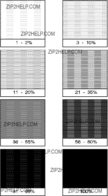
Figure

Figure

Fill Rectangular Area Command
This command fills (prints) a rectangular area of the specified width and height with the specified area fill.
EC * c # P
#=0 - Black fill (rule) 1 - Erase (white) fill 2 - Shaded fill
3 -
4 -
5 - Current pattern fill
The current pattern is not applied to a rectangular area unless specified by this command.
The fill or pattern used as the current pattern is selected using the Select Current Pattern (EC*v#T) command. For a detailed description of the Select Current Pattern command refer to Chapter 13, The PCL
Print Model.
Black fill (value field 0), also known as black rule, and the white fill (value field of 1) ???patterns??? do not have a choice of different patterns, and thus do not require a pattern specification using the Pattern ID command.
The upper left corner of the rectangular area is located at the cursor position when printing a rectangular area. After printing the rectangular area the cursor is returned to the upper left corner; the cursor position does not change positions as a result of printing a rectangular area.
Rectangular areas are independent of the text area and perforation skip mode; these boundaries are ignored (rectangles are not clipped at these boundaries). Addressable rectangular areas are limited to the logical page. Rectangular areas that extend outside the logical page are clipped at the logical page boundaries (refer to Figures
Transparency mode, described in Chapter 13, controls how the area fill pattern is applied to the page. Refer to the following section for a description of how transparency mode affects the rectangular fill area.
A white fill ???erases??? any data placed within the rectangular area prior to receipt of the white fill, regardless of the transparency mode settings. Data placed in a previously erased area is visible.
Pattern Transparency for Rectangular Area Fill
Pattern transparency, described in Chapter 13, under ???Pattern Transparency Mode Command,??? affects how a pattern is applied to the rectangular fill area. Rectangular areas are special case images for transparency mode. The pattern and pattern type are selected by the Pattern ID command (EC*c#G) and the Fill Rectangular Area (EC*c#P) command (described earlier in this chapter).
When applying a pattern (area fill) to the rectangular area, the usual transparency mode settings apply. The pattern transparency mode determines the effect white pixels of the pattern have on the destination for value fields 0 (black fill), 2 (shaded fill), 3
The ???0??? bits of the area fill are either applied (opaque) or ignored (transparent) based on the transparency mode setting (see Figure
The effect of transparency modes on rectangular areas is illustrated in Figure

Figure
Rectangular Area Fill Examples
This section shows example usage of area fill commands to print
Solid Fill (Black/White)
To print a 900 by 1500 Unit black rule (3 inches by 5 inches at 300
1 1. Position the cursor:
EC*p300x400Y
This moves the cursor to PCL Unit position (300, 400) within the PCL coordinate system.
2 2. Specify the width of the rule:
EC*c900A
This sets the rule width to 900 PCL Units (3 inches at 300
3 3. Specify the height of the rule:
EC*c1500B
This sets the rule height to 1500 PCL Units (5 inches at 300
4 4. Print the rule:
EC*c0P
This example prints a black filled rectangular area.
5 5. Position the cursor inside the rectangular area:
EC*p600x700Y
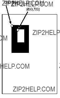
66. Specify the width and height for the smaller white fill rectangular area:
EC*c300a600B
7 7. Select the white fill and print.
EC*c1P
Figure
Shaded Fill
To print a 900 by 1500 Unit 25% shaded rectangle (3 inches by 5 inches at 300
1 Position the cursor:
EC*p300x400Y
This moves the cursor to PCL Unit position (300, 400) within the PCL coordinate system.
2 Specify the width of the rectangle:
EC*c900A
This sets the rectangle width to 900 PCL Units (3 Inches at 300

3 Specify the height of the rectangle:
EC*c1500B
This sets the rectangle to 1500 PCL Units (5 inches at 300
4 Specify the Pattern ID:
EC*c25G
This sets the Pattern ID to 25.
1 Print the rectangular shaded area:
EC*c2P
This example prints the following:
Figure
To print a 900 by 1500 Unit rectangular area (3 inches by 5 inches at 300
1. Position the cursor: EC*p300x400Y
Moves the cursor to PCL Unit position (300,400) within the PCL coordinate systems.
2. Specify the width of the rectangle: EC*c900A
Sets the rectangle width to 900 PCL Units (3 inches at 300
3. Specify the height of the rectangle: EC*c1500B
Sets the rectangle height to 1500 PCL Units (5 inches at 300
4. Specify the Pattern ID:
EC*c1G
Sets the Pattern ID to 1.
5. Print the rectangular

This example prints the following:
Figure
This example shows how to print a
The following commands define a 600 PCL Unit square rectangular area, select ID number 3, and print the
1 Position the cursor:
EC*p300x400Y
Moves the cursor to PCL Unit position (300,400) within the PCL coordinate systems.
2 Specify the width and height of the rectangle:
EC*c600a600B
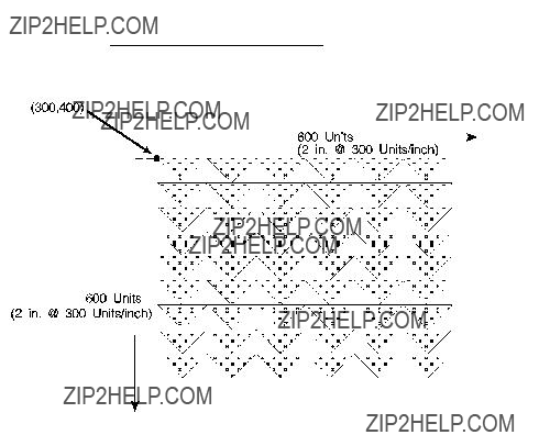
Sets the rectangle width and height both to 600 PCL Units (2 x 2 inches at 300 Units/inch).
3 Specify the Pattern ID:
EC*c3G
Sets the Pattern ID to 3.
4 Print the
EC*c5P
This example prints as shown in Figure
Figure

15 Raster Graphics
Introduction
A raster image is an image composed of dots. Pictures in newspapers or on television screens (also, a page printed by this printer) are examples of raster images. The PCL language includes commands for printing raster graphic images. These commands enable the LaserJet printer to receive binary data and print it as a raster image.
The binary data used to create a raster image is divided into dot rows: a row describes a
Figure
Since it takes a considerable amount of data to create even a small raster image, several methods are provided to reduce the amount of data needed to define an image. (Note, that the above illustration creates a rectangle 0.013 by 0.027 inches; a binary ???1??? = 1 dot = 1/300 inch.) These reduction techniques include

several binary data compression methods, and additional reduction techniques associated with the raster area feature (see Figure
Figure
Data compression methods include:
In addition to the compression methods, the raster area feature provides some other raster reduction techniques which utilize a defined raster area. The raster area is defined by a width and height which are set using the Raster Width and the Raster Height commands.
Zeroed rows at the top and within the raster image can be eliminated by using the
Trailing zeroed full rows at the end of the raster image need not be sent. The printer automatically fills in any unsent zeroed rows from the end of the raster image (last raster row with any ???1???s) to the bottom of the raster area.
The final data reduction technique provided by the raster area involves the printer???s ability to fill in trailing zeros to the edge of the raster area. Any zeros following the last ???1??? in the raster row to the edge of the picture area need not be sent. The printer automatically fills them. This technique eliminates the need to transmit raster data rows that are all the same length, as required in a raster image which does not use the raster area feature.
The raster area represents a boundary. Within this boundary the printer
When the raster area reduction techniques are used in conjunction with the raster compression techniques, a considerable savings in data can be realized. This results in a saving of host storage and data transmission time. However, these reduction techniques do not reduce the amount of printer memory required for page formatting.
Raster Graphics Command Sequence
PCL raster commands include: Start Raster Graphics and End Raster Graphics commands, Transfer Raster Data by Row, Raster Compression, Raster Presentation, Raster Resolution, Raster Height and Raster Width (which define the raster area), and Raster Y Offset commands. The normal sequence of execution for these commands is shown below:
Table
Raster Presentation
Raster Resolution
Raster Height
Raster Width
Start Raster Graphics
Y Offset
Raster Compression
Transfer Raster Data
M
Transfer Raster Data
Y Offset
Transfer Raster Data
M
Y Offset
Raster Compression
Transfer Raster Data
M
Raster Compression
Transfer Raster Data
End Raster Graphics
The emphasis in the previous command sequence is that the Raster Presentation Mode, Raster Resolution, Raster Height, and Raster Width are all set outside the start..data..end sequence of commands. Also, the entire image is sent during the start..data..end sequence, choosing the most effective compression method for each raster row of data.


Raster Graphics Resolution Command
Raster graphics can be printed at various resolutions. This command designates the resolution of subsequent raster data transfers in
EC * t # R
#= 75 - 75
150 - 150
200 - 200
300 - 300
600 - 600
This command must be sent prior to the start graphics command. The factory default resolution is 75
1.Only available if the printer is configured for resolution=600 dpi.
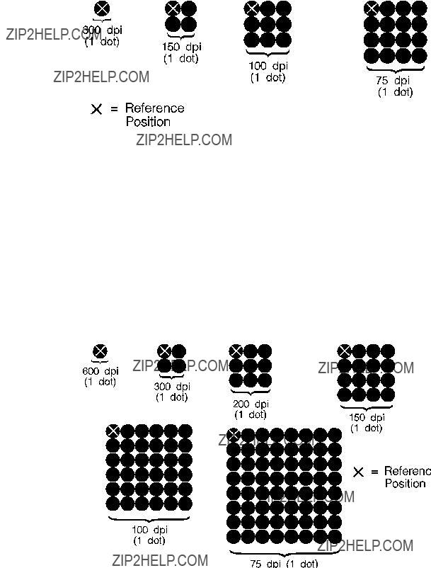
Figure
Raster Graphics Presentation Mode Command
The Raster Graphics Presentation command specifies the orientation of the raster image on the logical page.
EC * r # F
#=0 - Raster image prints in orientation of logical page 3 - Raster image prints along the width of the physical
page
A value of 0 indicates that a raster row ???will be printed in the positive
A value of 3 indicates that the raster graphics will be printed along the width of the physical page, regardless of logical page orientation. In portrait orientation, a raster row is printed in the positive
In landscape orientation, a raster row is printed in the positive
Table

Figure
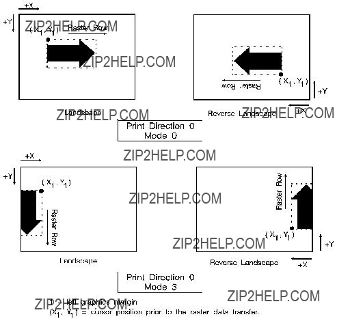
Figure

Raster Height Command
The Raster Height command specifies the height in raster rows of the raster area. Height is the direction perpendicular to the direction that raster rows are laid down, hence, height is subject to the current raster presentation mode and print direction (see Figure

Upon receiving an End Raster Graphics (EC*rC) command, the cursor position is set to the left graphics margin of the next raster row after the raster height boundary.
Figure
Raster Width Command
The Raster Width command specifies the width in pixels of the raster area. Width is in the direction that the raster rows are laid down, hence, width is subject to the current raster presentation mode and print direction (see Figure

Figure
Start Raster Graphics Command
The Start Raster Graphics command identifies the beginning of the raster data and also specifies the left graphics margin.
A value of 0 specifies that the left graphics margin is at the default left margin of the page
Once a Start Raster Graphics command is received by the printer, raster graphics resolution, raster graphics presentation mode, raster height, raster width, and left raster graphics margin are fixed until an end raster graphics command is received.

Once in Raster Graphics Mode, PCL commands and text imply an End Raster Graphics (EC*rC) except for the following commands:
zTransfer Raster Data
zSet Raster Compression Method
zRaster Y Offset
In addition, the following commands are ignored (i.e., locked out) while in Raster Graphics Mode and do not imply an End Raster Graphics command:
If source and/or transparency modes have been set, frequent start/end graphics commands in an image can result in a memory overflow condition.
Raster Y Offset Command
The Raster Y Offset command moves the cursor position vertically the specified number of raster lines from the current raster position in the raster area.
EC * b # Y
#=Number of raster lines of vertical movement
This command is recognized only while in raster graphics mode and only within the raster area.

Set Compression Method Command
The Set Compression Method command allows you to code raster data in one of four compressed formats:
EC& * b # M
#=0- Unencoded
1-
2- Tagged Imaged File Format (TIFF) rev. 4.0
3- Delta row compression
4- Reserved
5- Adaptive compression
Unencoded (Method 0)
This is a simple binary transfer of data: no compression. Each bit describes a single dot. Bit 7 of the first byte corresponds to the first dot within the raster row, bit 0 corresponds to the eighth dot, and so on.
A repetition count of 0 signifies the pattern in the data byte is not repeated (it occurs only once). A repetition count of 1 signifies the pattern occurs twice. The repetition count can range from 0 to 255 for a repetition of 1 to 256 times.
[(Repetition count byte
Tagged Image File Format Encoding (Method 2)
Tagged image file format encoding interprets raster data as TIFF ???Packbits.??? This format combines features of methods 0 and 1. A control byte precedes the raster data (pattern bytes). The control byte identifies whether the pattern byte(s) represent a byte that is to be repeated some number of times (up to 127), or represent some number of bytes (up to 127) which are to be printed as is (literal).
The sign of the number in the control byte identifies whether the byte or bytes that follow represent a literal pattern or byte to be repeated. A positive number (1 to 127) indicates that the bytes are literal. A negative number
As mentioned, for a byte to be repeated, the control byte must be a negative value as represented by the twos complement. For example, to repeat a pattern three times would require the twos complement of the number 3. The twos complement is computed as follows. The binary of 3 is 00000011. Complement each bit to get 11111100, then add one to this value to produce 11111101, the twos complement. The decimal value of this number, 253, used in the control byte, produces a repetition of 3 bytes for a total of 4 occurrences of the pattern.

The range of numbers for the control byte is shown below.
Table
Table
1.These negative values are represented by taking the twos complement of the value of the number.

TIFF encoding also allows you to include a
Examples:
The following examples show how a raster row can be coded using
Table
Unencoded
EC*r1A
EC*b0m7WUUUUATT
EC*rC
EC*r1A
EC*b1m6W(3)U(0)A(1)T
EC*rC
TIFF Encoding
EC*r1A
EC*rC
In the TIFF encoding example above, parenthetical expressions
are used to identify control bytes. For example, the byte
Delta Row Compression (Method 3)
Delta row compression identifies a section of bytes in a row that is different from the preceding row, and then transmits only that data that is different (the delta data). If a row is completely different from its preceding row, then the entire row must be sent as the delta (not very efficient); if only one bit is different, then only one byte is identified and sent. To reassemble the raster data rows, the printer takes the current row (referred to as the seed row) and makes the changes indicated by the delta data, to create the new row. The new row (which becomes the new seed row) is used by the next delta compression data to create another row.
A delta compression row consists of two parts, a command byte and the replacement bytes, as shown below:
[(Command byte)(1 to 8 Replacement bytes)]
The command byte identifies two things: 1) the number of replacement (delta) bytes that follow; and, 2) where to position the replacement byte string (the left offset). The replacement bytes are some number (up to eight bytes) of consecutive bytes that are used to create the new row from the seed row.

If more than eight replacement (delta) bytes are needed, additional command byte/replacement bytes may be added, as shown below:
EC*3m#W [(Command Byte)(1 to 8 Replacement Bytes)][(Command Byte)(1 to 8 Replacement Bytes)]. . .
In the command byte, the upper three bits identify the number of replacement (delta) bytes (which can be 1 to 8 bytes). The lower five bits identify the location the replacement bytes are to be positioned. This position is identified as some number of bytes in, from the first untreated byte, referred to as the offset. For example, if there are 5 replacement bytes and the offset is 7, then the replacement bytes replace byte 7, 8, 9, 10, and 11 (the five bytes beginning at byte 7 from the seed row).
If there is more than one replacement in a row, the second offset is counted from the next untreated byte in the row: the first byte following the last replacement byte.
Figure

As mentioned, the offset is contained in the lower five bits of the command byte allows for offset values from 0 to 31. Compression mode allows offsets larger than 31 bytes as follows:
zAn offset value of
zA value of 31 indicates that the next byte following the command byte is an additional offset byte which adds to the first (32) offset value. This allows offset values larger than 31. Also, if this second offset byte is set to 255 (all ones), additional offset bytes follow until the required offset value is obtained. When the formatter detects an offset byte less than 255, it is assumed to be the last offset value and the offset bytes are then totaled (added). The following example shows an offset larger than 31:
Figure
The total offset 414, which is the sum of the three offset values: 31 + 255 + 128.
Seed Row
The seed row is basically the current raster data row; the row being printed. It is maintained by the printer for use by delta row compression. The delta compression replacement bytes are applied to the seed row to create the new row. This new data row is printed and becomes the new seed row.
The seed row is updated by every raster graphic transfer, regardless of the compression method. This allows delta compression method to be mixed with other methods to achieve better compression performance.
Repeating a Row
EC*b0W
When using the delta compression method, it is possible to repeat or copy the previous raster row using the Raster Data Transfer command. This is accomplished by setting the Raster Data Transfer command, value field, to zero.
Printing A Zeroed Row (Setting the Seed Row to Zero)
EC*b1Y
Example: Delta Row Compression
The following example demonstrates how to compress the following data using the delta row compression. (The bytes highlighted in italic type indicate those bytes needing replacement ??? those bytes that are different from the previous row, the seed row.)
Table
EC*r1A ??? The start raster graphics command initializes the seed row to all zeros.
Row 1 ??? EC*b3m2W(00000001)(11111111)
The 3m selects the delta row compression method and the 2W indicates that 2 bytes of data to follow. The first three bits of the first data byte, the command byte, signify a single byte replacement (all three bits are 0). The next five bits indicate an offset of 1 byte from the current position. The replacement byte follows and contains
11111111.
Row 2 ??? EC*b2W(00000010)(11110000)
The first three bits of the command byte indicate that one byte will be replaced, and the next five bits indicate a relative offset of 2, so the replacement will occur 2 bytes from the current position. The replacement byte follows and contains 11110000.
Row 3 ??? EC*b5W(00000000)(00001111)(00100010) (10101010)(10101010)
As in the other rows, the first three bits of the command byte are zero, indicating a single byte replacement. The five offset bytes indicate a relative offset of zero bytes. The replacement byte follows and is 00001111. The third byte is another command byte and the first three bits signify the replacement of two bytes (the top three bits are 001). The offset bits indicate an offset of two bytes from the current position. The fourth and fifth bytes are the two replacement bytes.
Adaptive Compression (Method 5)
Adaptive compression enables the combined use of any of the four previous compression methods (0 through 3), and it includes the ability to print empty (all zeros) rows or to duplicate rows.
Adaptive compression interprets a raster image as a block of raster data rather than as individual rows. The result of this interpretation is that the Transfer Raster Data (EC*b#W) command is sent only once at the beginning of a raster data transfer, and the value field (#) identifies the number of bytes in the block (all rows). For the other compression methods, the Transfer Raster Data command is sent at the beginning of each row and the value field (#) identifies the number of bytes for that row only.
The size of a block is limited to 32,767 bytes. (32,767 bytes is the number of compressed bytes and not the size of the uncompressed data). To transfer greater than 32,767 bytes, send multiple blocks.
Adaptive compression uses three control bytes at the beginning of each row within the block. The first of these bytes, the command byte, identifies the type of compression for the row. The two following bytes identify the number of bytes or rows involved. The format for adaptive compression raster rows is shown below:
<command byte><# of bytes/rows - upper byte><# of bytes/rows - lower byte> ...
...<first raster row byte>...<last raster row byte>
The command byte designates the compression method, empty row, or row duplication. Command byte values are shown below.
Table
For command byte values 0 - 3, the two <# of bytes/rows> bytes specify the number of bytes (row length) for the row. For command byte values 4 and 5, these bytes identify the number of empty or duplicate rows to print. The maximum value for these two bytes is 65,535; however, the image is clipped to the logical page. Thus, the value of these bytes should not exceed the maximum number of bytes/rows that can be printed on the current logical page size.
If an out of range command byte is encountered, the remainder of the block is skipped, the cursor is not updated, and the seed row is cleared.
Compression methods 0 - 3 are the compression methods used by the Set Compression Method command. Value fields 4 and 5 are features for the adaptive compression method and are explained below.
Empty Row
A command byte of 4, empty row, causes a row of zero???s to be printed. The number of rows printed depends on the value contained in the two <# of bytes/rows> bytes following the command byte. The empty row operation resets the seed row to zero and updates the cursor position.
Duplicate Row
A command byte of 5, duplicate row, causes the previous row to be printed again. The row can be duplicated the number of times indicated by the value contained in the <# of bytes/row> byte.
Duplicate Row updates the cursor position but does not change the seed row.

zFor method 3 - Since delta row compression requires that the seed row be available whenever raster graphics mode is entered,
the seed row is initialized to zeros upon raster graphics mode
entry (EC*r#A). The seed row is also initialized upon receipt and completion of each raster block.
zFor method 3 - If the row length terminates the data before the control byte value is satisfied (literal byte count greater than row length), the data following the control byte (if any) is printed as text. The cursor is incremented.
zFor method 3 - if the row length is equal to one, the current row is duplicated, and the cursor is incremented.

Transfer Raster Data Command
The Transfer Raster Data command is used to transfer a row of raster data to the printer.

End Raster Graphics Command
The End Raster Graphics command signifies the end of a raster graphic data transfer.
EC * r C
zReceipt of this command causes 5 operations:
zResets the raster compression seed row to zeros.
zMoves the cursor to the raster row immediately following the end of the raster area (if a source raster height was specified).
zAllows raster commands which were previously locked out to be processed.
zSets compression mode to 0 (no compression)
zDefaults the left graphics margin to
Raster Graphics Example
To transfer an unencoded raster graphic image (see Figure
Table
1. Position the cursor:
EC*p300x400 This moves the cursor to PCL Unit position Y(300, 400) within the PCL coordinate
system.
2. Specify the raster graphics resolution:
3. Specify the raster graphics presentation method:
5. Transfer the raster data to the printer:
Divide the image into dot rows and transfer each dot row to the printer as a string of bytes, as illustrated on the following page.
6. Signify the end of the raster graphic image transfer:
Table
The brackets and commas are not part of the raster data command; they are used only to delineate the data.
Figure
16 Status Readback
Introduction
This chapter describes the PCL status readback features. PCL status is requested from the printer with the commands described in this chapter. Following a status request, the printer generates a status response. This response consists of ASCII data which is sent directly from the printer, through the I/O, back to the host. Status readback allows you to obtain information from the printer such as: available printer (user) memory, current available fonts and symbol sets, and the ID numbers
of downloaded macros and
The contents of this chapter are listed below:
zIntroduction
???Memory Status Request
???Entity Status Request
zStatus Response Syntax
zSet Status Readback Location Type Command
zSet Status Readback Location Unit Command
zInquire Status Readback Entity Command
zEntity Status Responses
???Font
???Font Extended
???Macro
???
???Symbol Set
zEntity Error Codes
zFree Space Command
???Memory Status Response
???Memory Error Response

zFlush All Pages Command
zEcho Command
zStatus Readback Programming Hints
For status readback to work, the host system must contain a
Memory Status Request
It is possible to identify the amount of available user memory using the memory status request. Being able to identify the available memory enables a user to determine whether sufficient memory is available for the entity being downloaded, potentially avoiding a printer memory overflow condition (control panel error 20, memory overflow).
An example memory request with its associated response is shown below.
Table
Table
Entity Status
It is possible to request status for the printer???s entities. An entity is a font, symbol set, macro, or
Location type refers to the memory locations which store entities. These memory locations include internal ROM, RAM (for downloaded entities), cartridges,
Location unit refers to a specific location (or device) within the location type. For example, location unit ???1??? for location type ???cartridge,??? identifies the left cartridge on a printer with two cartridges; or, unit ???1??? for location type ???downloaded,??? identifies the temporary fonts (as opposed to permanent).
The location type and unit are described in detail under the location type and unit status readback command descriptions provided later in this chapter.
Once the location type and unit are specified, the status can be requested using the Inquire Status Readback Entity command. This command identifies the entity (font, symbol set, macro, or
A basic entity status request is shown in the example below. This example identifies a status request for downloaded permanent fonts. The example also includes a status readback response at the bottom. Note that this example shows only one possible request/response; for more detailed information, refer to the status readback command descriptions provided later in this chapter.
Table
Table
In addition to the normal status responses, if an invalid request is made, the printer returns an error response. Error responses are described under the Inquire Status Readback Entity command, later in this chapter.

Note
Note
Status Response
When the printer receives a status request (command), it processes that request and forms the response data. This data is then stored in an I/O status buffer. The response is saved in this buffer until it is either read (by any user) or the printer is turned off.
In addition to clearing the status buffer by reading the status response or by turning off the printer, status responses are cleared if one the following settings are changed:
zPrinter resolution (600/300)
zPage protection
zLanguage personality
Status requests and their associated response are processed in the order in which they are received.
The number of responses the printer can buffer varies, depending on internal printer operations. When requesting status, especially in the case where multiple applications or users are sharing one printer, HP recommends that you request one item, and then read its response prior to making another request.
Since the printer may contain a status response requested by a previous application???s operation, it is important to use the Echo command (described later in this chapter) to synchronize your application???s request with the printer???s responses. Refer to the Echo command description and to the ???Programming Hints??? section at the back of this chapter for additional information.
The number of status responses a printer can buffer varies from printer to printer. The HP LaserJet 4 printer can store 5 responses. Refer to the PCL 5 Comparison Guide for printer specific information.
A status response is returned to the printer I/O port from which it was requested.

Status Response Syntax
All status responses start with the letters ???PCL??? followed by a Carriage Return control code (decimal 13; <CR>) and a Line Feed control code (decimal 10; <LF>). In addition, each remaining line of the response is terminated by a Carriage Return and Line Feed control code. Finally, status responses are terminated by a Form Feed control code (decimal 12; <FF>). The basic syntax for the status response is shown below.
PCL<CR><LF>
INFO TITLE<CR><LF>
KEYWORDn=DATAn<CR><LF>
KEYWORDn=DATAn<CR><LF>
M
<FF>
TITLE, KEYWORDn, and DATAn are strings that vary depending on the particular status readback command being executed. Each status readback response has one or more keyword lines associated with it. A slight variation of this is the Echo command response. This response is shown below.
PCL<CR><LF>
INFO MEMORY<CR><LF> TOTAL=100000<CR><LF> LARGEST=25000<CR><LF> <FF>

Set Status Readback Location Type Command
The Set Location Type command sets the status location type to the specified value. Location type is used in conjunction with the location unit to identify an entity location for a status request (Inquire Status Readback Entity command).
EC * s # T
#=0- Invalid location
1 - Currently selected
2 - All Locations
3 - Internal
4 - Downloaded Entity
5 - Cartridge
7 -
If a value outside the range is received, the location type is set to 0.
When the location type is 0 and an Inquire Entity command is received, an error response is generated (refer to the ???Status Response Error Codes??? section later in this section for additional information).
A printer reset returns the location type setting to 0.
The printer retains the location type setting. If the Set Status Readback Location Type command is not sent to change the setting for an entity request, then the existing location type setting is used.
Set Status Readback Location Unit Command
The Set Location Unit command sets the status location unit to the specified value. Location unit is used in conjunction with the location type to identify an entity location for a status request (Inquire Status Readback Entity command). Note that the unit value is interpreted differently, depending on the location type specified.
EC * s # U
Table
* - For location type values 0, 1 and 2, the unit value is ignored; it may be any value.

Inquire Status Readback Entity Command
The Inquire Entity command identifies the entity type and causes the printer to create a status response for the entity specified in the status readback location (type and unit).
EC * s # I
#=0- Font 1 - Macro
2 -
3 - Symbol Set (for unbound scalable fonts)
4 - Font Extended
The entity status responses for the value field parameters vary depending on the setting of the location type and location unit (refer to the Set Location Type and Set Location Unit commands described on the preceding pages).
The entity status and error responses are described on the following pages.
Entity Status Responses
The status response for an Inquire Status Readback Entity command varies depending on the type of entity requested. The status responses for font, font extended, macro,
and symbol set are described below.
Font Response
The status response information returned for font (inquire entity value field 0) varies. Depending on whether the printer???s font is a bitmap, unbound scalable, or bound scalable, different keywords are returned. The response is also somewhat different if the location type is set to 1 (currently selected, as explained in more detail later). The list of possible keywords for a font request is shown below.
SELECT=
SYMBOLSETS=
LOCTYPE=
LOCUNIT=
An example of an inquire entity font (entity type 0) status response is shown below. Notice the variation in the keyword lines for the three fonts, listed in order below:
Internal, bitmap, Line Printer
Internal, unbound scalable, CG Times italic
Downloaded, bound scalable, (CG Palacio)
Font status:
PCL
INFO FONTS
SELECT=???<Esc>(8U<Esc>(s0p16.67h8.5v0s0b0T???
SELECT=???<Esc>(s1p__v1s0b4101T???
SYMBOLSETS=???0D,0I,0N,0S,0U,1E,1F,1G,...???
SELECT=???<Esc>(1U<Esc>(s1p__v0s0b4111T<Esc>(21X???
M
In a font status response, individual fonts are identified by the ???SELECT=??? keyword line, as shown in the example above. This line identifies the font by specifying the font selection characteristics (symbol set, spacing, pitch, height, style, stroke weight, and typeface). The characteristics are listed as they would be sent to the printer to select the font (in priority order, highest priority to lowest). ???SELECT=??? is returned for all font types.

Unbound Scalable Fonts
For unbound fonts, since multiple symbol sets can be associated with an unbound font, the ???SYMBOLSETS=??? keyword is added to list the available symbol sets and the symbol set sequence is no longer present in the ???SELECT=??? line. For example, the printer???s internal unbound scalable Courier (medium, fixed spaced) font and CG Times (bold italic, proportional spaced) fonts would be returned as shown below.
PCL
INFO FONTS
SELECT=???<Esc>(s0p__h0s0b4099T???
SYMBOLSETS=???0D,0I,0N,0S,0U,1E,1F,1G,...
SELECT=???<Esc>(s1p__v1s3b4101T???
SYMBOLSETS=???0D,0I,0N,0S,0U,1E,1F,1G,...???
Soft Fonts
For soft fonts (bitmap, bound scalable or unbound scalable), the font ID number is also included at the end (a font downloaded with an ID of 27 would be presented as ??? ...<Esc>(27X ??? ). For example, a downloaded bitmap Courier with a font ID of 39 and a downloaded, unbound scalable, Dom Casual typeface with a font ID of 78 would be returned as shown below.
PCL
INFO FONTS SELECT=???<Esc>(8U<Esc>(s0p10.00h12.0v0s0b3T<Esc>(39X??? SELECT=???<Esc>(s1p__v1s0b4148T<Esc>(78X??? SYMBOLSETS=???0D,0I,0N,0S,0U,1E,1F,1G,...???
Location Type 1 (Currently Selected) Font
For a status location type 1 (currently selected) font, only a single font, the printer???s currently selected font, is returned. The keywords and data returned are described as follows.
z???LOCTYPE=??? and ???LOCUNIT=??? are returned after the ???SELECT=??? line for each font.
z???SELECT=??? line changes for bound and unbound scalable fonts.
???For all scalable fonts, the actual size (either height or pitch) is listed in place of the underscores.
???For unbound scalable fonts, the symbol set currently bound to the font is listed.
zFor all fonts, if the font is a secondary font, then the ???(??? characters are replaced by ???)??? characters in the ???SELECT=??? line.
???LOCTYPE=??? identifies the location type of the currently selected font. The value returned corresponds to the value field of the Set Status Readback Type command.
???LOCUNIT=??? identifies the location unit of the currently selected font. The value returned corresponds to the value field of the Set Status Readback Unit command.
For example, if the printer???s currently selected font is a bold 14 point Presentation bitmap font selected from a cartridge, and a font entity request with the location type set to 1 is made, the response would be returned as shown below.
PCL
INFO FONTS SELECT=???<Esc>(1U<Esc>(s0p10.00h14.0v0s3b11T LOCTYPE=5
LOCUNIT=1
For example, assume the printer???s currently selected font is unbound scalable Dom Casual font with the following characteristics:
zdownloaded (font ID of 78)
ztemporary
z
zsecondary font
z18 point
If an entity request is made with the location type set to 1 (currently selected), the following response is returned.
PCL
INFO FONTS SELECT=???<Esc>)8U<Esc>)s1p18.00v1s0b4148T<Esc>)78X??? LOCTYPE=4
LOCUNIT=1

Font Extended Response
The font extended response (inquire entity value field 4) provides a way to return the name and internal ID number of the font, as well as the ???SELECT=??? line. It is the same as a font status response (inquire entity value field 1), in that ???SELECT=,??? ???SYMBOLSETS=,??? ???LOCTYPE=,??? and ???LOCUNIT=??? are returned in the same manner. They are not
???DEFID=??? identifies the font???s internal ID number. This is the number which appears on the font printout. It is the number used to select the font as the default font from either the printer???s control panel or from
PJL (refer to the Printer Job Language Technical Reference Manual for information on PJL font selection). The ???DEFID=??? number consists of two parts, a location and an ID number, such as ???I 21,??? where ???I??? is the location and ???21??? is the font???s internal ID number. The possible locations are listed below:
Since temporary soft fonts do not have an internal ID number (they cannot be selected as the default from the control panel or PJL), NONE is returned as their ???DEFID=NONE???.
The font???s internal ID number is assigned to fonts by the printer. This number is different than the soft font download ID number assigned to a downloaded font using the Font ID (EC*c#D) command.

???NAME=??? is returned for font extended status requests only. It identifies the name of the font, such as, Courier, Times Roman, Univers, etc., and its treatment (such as BdIt - bold italic) as listed in the font printout.
For example, the font extended response for the printer???s internal bitmap Line Printer font and a downloaded unbound CG Palacio temporary font would be returned as shown below.
PCL
INFO FONTS EXTENDED
SELECT=???<Esc>(8U<Esc>(s0p10.00h12.0v0s0b0T???
DEFID=???I 45???
NAME=???Line Printer???
SELECT=???<Esc>(s1p__v1s3b4111T<Esc>(7X???
SYMBOLSETS=???0D,0I,0N,0S,0U,1E,1F,1G,...???
DEFID=NONE
NAME=???CG Palacio BdIt???
SELECT=???...
M
Or, for example, a font extended response with the location type set to 1 (currently selected) where the currently selected font is the internal CG Times (18 point specified for printing) bold, the response would be returned as shown below.
PCL
INFO FONTS EXTENDED
SELECT=???<Esc>(8U<Esc>(s0p18.00h0s3b4101T???
DEFID=???I 002???
NAME=???CG Times Bd???
LOCTYPE=3
LOCUNIT=1
Macro Response
The status response for macros (inquire entity value field 1) lists all of the macro IDs (???IDLIST=???) for the macros in the specified location.
A macro status response might appear as shown below.
PCL
INFO MACROS
IDLIST=???1,3,8,29,32???
The status response for
A
PCL
INFO PATTERNS
IDLIST=???1,2,9,13,27,456???
If the location type is set to 1 (currently selected), then ???LOCTYPE=??? and ???LOCUNIT=??? lines are added.
???LOCTYPE=??? is returned for a status location type 1 request only. It identifies the location type of the currently selected pattern.
???LOCUNIT=??? is returned for a status location type 1 request only. It identifies the location unit of the currently selected pattern.
A
PCL
INFO PATTERNS
IDLIST=???88???
LOCTYPE=4
LOCUNIT=2
If the current pattern is set to one of the internal
PCL
INFO PATTERNS
ERROR=NONE

Entity Error Codes
If you request
zInvalid Entity
zInvalid Location
zNone
zInternal Error
ERROR=INVALID ENTITY
If the entity type specified in the escape sequence is out of range or unsupported, an invalid entity error is returned. For example, if the Inquire Entity command contained an out of range value of 8 (EC*s8I), the following error response would be generated.
PCL
INFO ENTITY
ERROR=INVALID ENTITY
ERROR=INVALID LOCATION
If the entity type is valid but the location (either the type, the unit, or the combination) is invalid or if the specified device is not installed, an invalid location error is returned. For example, if you requested a status for a cartridge type but identified an out of range location unit of 9 (EC*s5t9U), the following error response would be generated:
PCL
INFO FONTS
ERROR=INVALID LOCATION

ERROR=NONE
If the entity type and location are valid, but there are no entities of the specified type in that location, or if the type is inappropriate for the specified entity (internal
PCL
INFO SYMBOLSETS
ERROR=NONE

Free Space Command
The Free Space command returns the amount of available memory. This response returns two values: the total available memory, and the largest available block of memory (refer to the ???Memory Status Response??? section later in this chapter for additional information).
EC * s 1 M

Note
Note
Note
If you determine there is insufficient memory to hold the data to be downloaded, some action is required. One method to make more memory available is to send the Flush All Pages command. This causes the printer to clear (process) the current page data from memory without accepting any new data for processing (refer to the ???Flush All Pages Command??? described later in this section). Another, more comprehensive method to clear memory is to send the Printer Reset (ECE) command. This not only removes data (deletes all temporary entities and the font cache) but also restores the User Default Environment settings (refer to the Printer Reset command
in Chapter 4, ???Job Control Commands???).
To print characters from a scalable font, the printer converts the scalable character outlines into sized bitmaps. These bitmapped characters are created on a
The bitmap characters used on the first page of a job can remain in memory until the end of a job. These stored bitmap characters are referred to as the font cache.
When an HP LaserJet 4 printer (or later) reaches a memory low condition it automatically deletes all of the font cache. It is possible to delete the cache immediately using a Printer Reset command. A Printer Reset clears the font cache, clears temporary entities, and restores the user default environment.
Memory Status Response
A Free Space status response returns two values:
TOTAL=
LARGEST=
???TOTAL=??? identifies the total available user memory (in bytes). This value includes the largest block available and all smaller blocks.
Data downloaded to the printer is stored in a block (continuous section of free memory). If the printer does not have a large enough block to store the data, then the data is discarded and a memory error results.
???LARGEST=??? identifies the largest continuous block of available memory (in bytes).
An example response is shown below:
PCL
INFO MEMORY
TOTAL=100000
LARGEST=25000
The above example indicates that the printer has 100,000 bytes of available memory and the largest continuous block is 25,000 bytes.
Memory Error Response
If the Free Memory command value field is out of range (not 1), then the memory status response returns an invalid unit error. For example, if the Free Space command with a value of 2 (EC*s2M) were sent, the following error would be returned:
PCL
INFO MEMORY
ERROR=INVALID UNIT

Flush All Pages Command
The Flush All Pages command suspends accepting input data until all pages currently in the printer are printed. This gives the printer time to clear some memory.
EC & r # F
# =0- Flush all complete pages
All Pages command. If the memory status readback response indicates sufficient memory available to process a job, the Flush
All Pages command does need not be used. If the memory response indicates insufficient memory available to run the job, then the application should use the Flush All Pages command to make memory available, and then check available memory a second time.
When possible, use the Flush All Pages command only at the beginning of a print job, prior to the receipt and processing of any data. This minimized, to minimize performance reduction.

Echo Command
The Echo command echoes its value field (in ASCII format) back to the host.
EC * s # X
#=Echo value (ASCII)
If multiple users are requesting status, it can be difficult to distinguish one user???s status response from another. The Echo command provides the means to label status responses. Since the
at the beginning of a status request enables users to identify their status response data.
If the application sends the Echo command and Free Space command, the printer returns the response to the first Echo command and Free Space command, along with the response to the second request. The application will assume that the response received is the response to its last request. If the application uses random numbers in the Echo command, this type of
Echo Response
The Echo command returns the following response:
PCL
ECHO ValueField
where ???ValueField??? is the Echo command value field value that was selected (within the range
For example, if the Echo command,
PCL
ECHO
Status Readback Programming Hints
The following hints can assist in using the status readback feature.
zPCL status readback is useful during the development of applications. Status readback allows you to determine that fonts, macros,
zIf the printer does not contain sufficient memory to accept a downloaded entity, the printer discards the data. Status readback can be used to determine if the printer accepted a downloaded entity.
zStatus responses are directed to the printer???s I/O port from which the request is received. If the status is not read and the printer switches to another I/O port, the status response is not directed to that port. The status response returns if the printer switches back to the original port (see note on following page).
zYour application should work correctly when an unexpected status response is received. For example, when requesting a PCL status, it is possible that PJL could return an unsolicited status response, if PJL is enabled.
???All PCL status responses begin with the ???PCL??? header and end with the <FF> control code. When reading PCL status responses, your application should be able to read all the data between the ???PCL??? header and the <FF> control code. It should ignore any other status response syntax.
???Lines within the PCL status response begin with a specific keyword (those described in this chapter) and end with the <CR> and <LF> control codes. Future printers may support new keywords in the PCL status response. Your application should be designed to ignore those lines which it does not understand.
zThe first PCL status readback command an application should send is the PCL Echo command. A random number should be generated for the value field each time the command is sent. Your application should ignore all printer status readback data until the PCL Echo status readback response is received, echoing the number the application sent.
zTo clear any possible unread status responses from previous applications, an application, upon starting up, may want to read any pending responses until they are cleared from the printer.
