Using
HP 9000 Networking for
Manufacturing Part Number:
E0302
U.S. A.
??Copyright 2002
Using
HP 9000 Networking for
Manufacturing Part Number:
E0302
U.S. A.
??Copyright 2002

Legal Notices
The information in this document is subject to change without notice.
Warranty. A copy of the speci???c warranty terms applicable to your Hewlett- Packard product and replacement parts can be obtained from your local Sales and Service Of???ce.
Restricted Rights Legend. Use, duplication or disclosure by the U.S. Government is subject to restrictions as set forth in subparagraph (c) (1) (ii) of the Rights in Technical Data and Computer Software clause at DFARS
(c) (2) of the Commercial Computer Software Restricted Rights clause at FAR
3000 Hanover Street
Palo Alto, California 94304
U.S.A.
Use of this manual and ???exible disk(s) or tape cartridge(s) supplied for this pack is restricted to this product only. Additional copies of the programs may be made for security and
Copyright Notices. ??copyright 2002
Reproduction, adaptation, or translation of this document without prior written permission is prohibited, except as allowed under the copyright laws.
2

Contents
Patches Required for the March 2002
2. Overview of Installation and Con???guration
Planning
3. Con???guring VLANs Using SAM
4. Con???guring VLANs by Editing vlanconf File
5. Using lanadmin
Using the lanadmin
3

Contents
4

Tables
Table
5

Tables
6

Figures
Figure
7

Figures
8

What are
A Virtual LAN (VLAN) is a logical or virtual network segment that can span multiple physical network segments. Using VLANs, you can group
???department, such as engineering and manufacturing,
???type of user, such as power users or those with special needs,
???application, or
???project
instead of physical location (Figure
LAN 2
Physical View
Manufacturing VLAN
Logical View
VLANs isolate broadcast and multicast traf???c by determining which destinations should receive that traf???c, thereby making better use of switch and
What are
VLANs create broadcast domains using switches instead of routers. While VLANs in some environments may reduce the number of routers needed (and their latency), you still need a router if you want the VLANs to communicate with each other.

What are
Following are some of the features of
???
???HP VLANs are for use over fast Ethernet or gigabit Ethernet LAN cards running on
???

What are
Bene???ts of
Bene???ts of
The advantages of
???Physically dispersed workgroups can be logically connected within the same broadcast domain to appear as if they are on the same physical LAN.
???A single physical link can simultaneously serve several IP subnets when
???Switches no longer need to classify and tag traf???c. They focus on forwarding packets.
???Workgroups requiring increased security can be logically connected within the same broadcast domain. Broadcast traf???c will be isolated within the secure group.
???End stations using VLANs can offer rudimentary class of service (CoS) locally by prioritizing traf???c for certain activities.
???
???

What are
Types of VLANs Supported by
Types of VLANs Supported by
The types of
???
Members of the same
???Protocol
???IP Subnet
Please refer to ???Planning

What are
Network switches and end stations that know about VLANs are said to be
When a
VLAN ID 12 bits
You must con???gure VLAN tagging on switch ports that interface to
To transmit tagged frames, you must con???gure a VLAN on the
What are
Server
HP Gigabit or Fast Ethernet
LAN Card Port

What are
System and Software Requirements
System and Software Requirements
Following are the hardware and software requirements for VLANs as of March 2002:
???Type of HP System Required
???
???OS Required
???
???VLANs work over all HP HSC and PCI 100Base LAN cards and all HP HSC and PCI 1000Base LAN cards.
Patches Required for the March 2002
The following patches are required in order to use the
These patch numbers are current at the time of publication and may be superseded. Check to see if these patches are superseded, and download patches at the following URL:

What are
System and Software Requirements

What are
Supported Switches
Supported Switches
???HP ProCurve 9304M
???HP ProCurve 4000M/8000M
???Extreme Summit 7i
???Cisco Catalyst 6509

What are
Unsupported Functionality
Unsupported Functionality
???GARP VLAN registration protocol (GVRP) is currently not supported.
???
???Any
???
???FDDI, Token Ring, ATM, 100VG, EISA, and

Overview of Installation and Con???guration
Planning
Planning
The following requirements must be satis???ed before setting up VLANs in an
???In order for both end stations of a VLAN to communicate, both the
???For VLANs to communicate with each other, an external
???If a hub is connected to a network of VLANs, every port on the hub must belong to the same VLAN. Hubs do not have the ability to provide VLANs to individual ports.
VLAN awareness does not provide any bene???t in a shared LAN environment (using hubs or repeaters). In these shared LAN environments, all stations see all traf???c whether it is VLAN tagged or not.
LAN Card with Two
VLANs Con???gured

 Port A2
Red VLAN
Green VLAN

 Port A4

Overview of Installation and Con???guration
How to Con???gure VLANs on the Switch
How to Con???gure VLANs on the Switch
IEEE 802.1Q compliant devices and legacy/untagged VLANs can coexist on the same networks, but legacy/untagged VLANS require a separate link, whereas the 802.1Q tagged VLANs can combine several VLANs into one link. On
When you assign a switch port to a given VLAN, you must implement the VLAN tag if the switch port will carry traf???c for more than one VLAN. Otherwise, the port VLAN assignment can remain untagged because the tag is not needed. On a given switch, use the untagged designation for a port VLAN assignment where the port is connected to a

Overview of Installation and Con???guration
How to Con???gure VLANs on the Switch

CAUTION
Overview of Installation and Con???guration
How to Con???gure VLANs on
How to Con???gure VLANs on
Choose Con???guration Method: Use SAM; Edit vlanconf; Use lanadmin
There are three ways to con???gure VLANs: the ???rst two methods preserve con???guration changes across reboots; the third applies changes immediately but doesn???t preserve con???guration changes across reboots:
To permanently save your con???gurations, you can either:
???Use the
If you use, SAM, con???guration doesn???t require a reboot to take effect.
or
???Edit the /etc/rc.con???g.d/vlanconf con???guration ???le using an editor such as ???vi.??? Changes will not take effect until the next reboot. Refer to ???Con???guring VLANs by Editing the vlanconf File??? in this document for instructions on editing the con???guration ???le for VLANs.
To temporarily con???gure VLANs on a live system, you can:
???Use the lanadmin command from the
If you use the lanadmin command to administer VLANs, those changes are not preserved across reboots. See ???Using the lanadmin Command for Administering VLANs??? for details on the lanadmin command.

Overview of Installation and Con???guration
Con???guration Process
Con???guration Process
Following are the steps to con???gure
1.Determine the network topology affected. Either draw the affected network topology or list it. Include all affected end
2.De???ne the VLANs. Decide, according to your requirements, which systems belong to which logical groups.
3.Assign VLAN IDs to each VLAN. Ensure that the assignments are consistent across endstations and switches; otherwise, stations will not communicate with each other. A VLAN ID can be any number between 0 and 4094 that is used only once within that port.
4.Determine which LAN card ports need tagged VLANs and which do not. Typically, you may need to put a server LAN card port in several VLANs while a desktop LAN card port can belong to just one VLAN.
5.Assign VLAN IDs to each LAN card port on end stations and switches. Mark VLANs on the switches as tagged or untagged according to the LAN card port to which they are connected.
6.On
Overview of Installation and Con???guration
Properties of a VLAN
Properties of a VLAN
When a VLAN is created on a given LAN card port, (see ???Creating a VLAN???), the system generates a virtual PPA or VPPA which can be used to send and receive 802.1Q tagged frames on that LAN card. Each
1.A VPPA is associated with a VLAN, the properties of which are determined by the create (or modify) command. The PPA of a physical interface doesn???t have a VLAN associated with it.
2.A VLAN doesn???t have a unique hardware instance. VPPA values are assigned such that they don???t overlap with hardware instance numbers of physical interfaces on the system.
Note: the PPA assigned to a LAN card port is the same as its hardware instance number.
3.A VLAN shares all the link properties of the physical interface on which it is con???gured. Any changes to the underlying physical interface will be propagated to all its VPPAs.
In the sample lanscan output in the section ???Displaying a VLAN and its Properties,??? lan5000 shares all the properties (such as speed, duplexity, MTU, MAC address) of the physical port with which it is associated, lan0.
4.All frames transmitted via a VPPA are VLAN tagged. Frames transmitted via a physical PPA are sent untagged.
5.lanadmin
6.lanadmin interactive mode displays and clears driver statistics for VPPAs.
Overview of Installation and Con???guration
Special Case of VLAN ID
Special Case of VLAN ID
Frames
VLAN ID 0 means that the frame doesn???t belong to any VLAN but has 802.1p priority information. Ensure that any switches used with
Promiscuous Mode Characteristics
Only one stream can be running in un???ltered promiscuous mode per physical interface plus all its VLAN interfaces put together.
The promiscuous stream will be able to see all frames transmitted or received on the physical LAN card

Overview of Installation and Con???guration
Allowable Values for HP VLANs
Allowable Values for HP VLANs
Table
For the format of the /etc/rc.con???g.d/vlanconf ???le, refer to
Overview of Installation and Con???guration
Allowable Values for HP VLANs
1 Default is an empty string; lanadmin will display it as UNNAMED.
Overview of Installation and Con???guration
Using VLANs with MC/ServiceGuard
Using VLANs with MC/ServiceGuard
You can create MC ServiceGuard
Example:
Overview of Installation and Con???guration
How is 802.1p Priority Set?
How is 802.1p Priority Set?
IP packets are classi???ed and marked into different priority levels and the markings are transported through a type of service (ToS) octet in the IPv4 header and a traf???c class ???eld in the IPv6 header.
Priority may be set by user, destination address, input port, output port, access priority, or by VLAN. User priority is a

Overview of Installation and Con???guration
How do Pri and ToS Override Affect My Inbound and Outbound frames?
How do Pri and ToS Override Affect My Inbound and Outbound frames?
Consider the following command.
lanadmin
This command will create a VLAN interface on PPA 6, with VID as the VLAN ID, PRI as the 802.1p priority, TOS as the IPv4 ToS value.
???All frames transmitted via the newly created interface will be VLAN tagged.
???The VLAN ID ???eld in the tag will be VID without exception.
???Please note that
The following information applies only to inbound and outbound IP traf???c.
???The 802.1p priority value in the VLAN tag is determined by the PRI, PO, and TOS settings as shown in Table
???The ToS value of an inbound IP packet header is determined by TOS, TO, and PRI settings as shown in Table

Overview of Installation and Con???guration
How do Pri and ToS Override Affect My Inbound and Outbound frames?

Overview of Installation and Con???guration
Setting 802.1p Priority, ToS, and Overrides
Setting 802.1p Priority, ToS, and Overrides
802.1p priority is the priority in the tag in the frame header. Switches can use the 802.1p priority.
ToS is the IP precedence in the IP header. Switches ignore ToS. Routers may use it.
The Priority Override Levels for Outbound Traf???c are as follows:
The ToS Override Levels for Inbound Traf???c are as follows:
Where to Get More Information
For information on using the lanadmin command to temporarily modify
man vlan.

Overview of Installation and Con???guration
Where to Get More Information


Con???guring VLANs Using SAM
Con???guring VLANs Using SAM
Con???guring VLANs Using SAM
You can use SAM to con???gure VLANs by completing the following steps:
1.Log in as root.
2.Check the
3.At the
4.At the SAM main window, double click:
Networking and Communications
5.There are then 2 ways to access VLAN con???guration. Either choose the icon Virtual LAN, or choose Network Interface Cards and then show the VLANs by using the List Pulldown.
SAM displays a list of
Figure

Con???guring VLANs Using SAM
Con???guring VLANs Using SAM
6.On the Virtual LAN screen, available
Figure
On this screen, you can optionally add a VLAN Name (31 chars, and unique within a LAN card), priority, ToS, and overrides. See the chapter ???Overview of Installation and Con???guration:??? or the online help for details.

Con???guring VLANs Using SAM
Con???guring VLANs Using SAM
Figure
Con???guring VLANs Using SAM
Con???guring VLANs Using SAM
On the Modify VLAN Properties screen, the ???elds are all optional; the data elements are the same as discussed in the chapter ???Overview of Installation and Con???guration:??? VLAN name, VPPA, priority, ToS, and overrides.
Figure
7.At any time, view the online help pulldown menu for doing any of the listed tasks or for ???nding help on a speci???c ???eld.

Con???guring VLANs Using SAM
Con???guring VLANs Using SAM


Con???guring VLANs by Editing vlanconf File
Modifying Parameters in vlanconf File
Modifying Parameters in vlanconf File
Following is the format of the /etc/rc.con???g.d/vlanconf ???le. To permanently save changes to this ???le, either use SAM or use a text editor such as ???vi.??? If you use the lanadmin command line interface to make changes to VLANs, your con???guration will not be preserved after reboots unless you modify the vlanconf ???le manually.
#vlanconf: configuration values to create VLAN Virtual
#Interface. This file will maintain the VLAN
#information across reboot, and will be modified
#by SAM. You can also edit this file.
#
# VLAN_PHY_INTERFACE : Physical interface name, see

# For each VLAN configuration, add a set of variable # assignments like the ones below, changing the index to ???[1]???, # ???[2]??? et cetera.
##############################################################
#
#Sample Entry
#VLAN_PHY_INTERFACE[1]=

Con???guring VLANs by Editing vlanconf File
Modifying Parameters in vlanconf File
#VLAN_ID[1]=
#VLAN_PRIORITY[1]=
#VLAN_TOS[1]=
#VLAN_PRI_OVERRIDE[1]=
#VLAN_TOS_OVERRIDE[1]=
#VLAN_NAME[1]=??????
#VLAN_VPPA[1]=
Example:
Following is an example where the physical interface lan0 has been assigned a VLAN ID of 1, default values for VLAN priority, VLAN ToS, VLAN priority override, VLAN ToS override, the name ???Red,??? and a VLAN PPA of 5000.
VLAN_PHY_INTERFACE[0]=lan0
VLAN_ID[0]=1
VLAN_PRIORITY[0]=0
VLAN_TOS[0]=0
VLAN_PRI_OVERRIDE[0]=CONF_PRI
VLAN_TOS_OVERRIDE[0]=IP_HEADER
VLAN_NAME[0]=Red
VLAN_VPPA[0]=5000

Using lanadmin

Using lanadmin
Using the lanadmin
Using the lanadmin
Administering VLANs
To con???gure VLANs, you use either the
If you use the lanadmin command line interface, your con???guration will not be preserved after reboots unless you also save the con???guration in the vlanconf ???le by either using SAM or editing it. See ???Modifying Parameters in vlanconf File??? in this document for the format of the
/etc/rc.con???g.d/vlanconf ???le.
lanadmin Syntax
If you use the lanadmin command line interface to work with VLANs, you can display the general usage string by typing:
lanadmin
General usage string:
lanadmin
[name <name> (31 characters alphanumeric string)]
[tos_override <level>(IP_HEADER, ETHER_HEADER, CONF_TOS or CONF_PRI,
default IP_HEADER)]
[pri_override <level>(CONF_PRI,IP_HEADER or CONF_TOS, default CONF_PRI)] <ppa>
[tos <ToS value> (range
[name <name> (31 characters alpha numeric string]
[tos_override <level>(IP_HEADER, ETHER_HEADER,

Using lanadmin
Using the lanadmin
CONF_TOS or CONF_PRI)
[pri_override <level>(CONF_PRI,IP_HEADER or CONF_TOS)] <vppa>
Using lanadmin to Create a VLAN
Assume that the system has the following con???guration as shown by the lanscan command output.
lanscan
MAC
Type Support Mjr#
ETHER Yes 119
ETHER Yes 119
To con???gure a VPPA with VLAN ID 454 and a priority of 6 on ???lan0???, execute the following command.
lanadmin
Successfully configured
lan5000: vlanid 454 name UNNAMED pri 6 tos 0 tos_override IP_HEADER pri_override
CONF_PRI ppa 0
This command created a VLAN ???lan5000??? on top of the physical interface lan0. The PPA associated with this VLAN, 5000, is referred to as a VPPA, short for Virtual PPA. Note: the parameters that were not speci???ed in the command have been assigned default values.
Displaying a VLAN and its Properties
You can use the default lanscan command to view all the interfaces as follows.
lanscan

Using lanadmin
Using the lanadmin
The VLAN (lan5000) appears in lanscan output just like a physical interface. VPPAs are identi???ed by the string ???VLANx??? in the hardware path, where x is a number and is unique per VPPA. In the lanscan output, VPPAs of a given physical interface are displayed just after the corresponding physical interface.
The verbose option of the lanscan command displays more information about the VLAN.
lanscan
Driver Specific Information vlan
.......................................................................
Vlan ID
454 0 6 0 CONF_PRI IP_HEADER UNNAMED
Using lanadmin to Set 802.1p Priority, ToS, and Overrides
The lanadmin
Using lanadmin to Query for VLANs on a System
The following command can be used to query for the list of VPPAs con???gured and their properties.
lanadmin
A sample output for the successful command is as follows:
Note: UNNAMED will be displayed as the VLAN name if there is no name associated with the VPPA.
Using lanadmin
Using the lanadmin
Querying for a Single VPPA on a System You can query the Virtual PPA using the following command:
lanadmin
The info command will return the output in the following format when successful.
Example: lanadmin
Querying for a Base VPPA Value You can determine the minimum acceptable value for a Virtual PPA using the following command:
lanadmin
Example: lanadmin
5000
Using lanadmin to Modify a VLAN
The properties of a VLAN can be modi???ed using lanadmin. For example, to change the VLAN ID to 53 and priority to 3, on lan5000, type:

Using lanadmin
Using the lanadmin
lanadmin
Successfully modified lan5000
Old value: vlanid 454 pri 6
New value: vlanid 53 pri 3
After the modi???cation, the lanscan
Driver Specific Information vlan
.......................................................................
Using lanadmin to Delete a VLAN
Before deleting a VLAN, ensure that there are no applications or upper layer protocols active on the VLAN by running:
lanadmin
This command displays the applications and commands that are presently using the interface. For example, if the only thing done to lan5000 is con???gure an IP address, the lanadmin
lanadmin
ifconfig ifconfig
Since ifconfig command is used to con???gure an IP address the same is displayed. There are two entries because when an IPv4 address is con???gured using ifconfig, it con???gures both IP and ARP on the interface.
To remove the IP and ARP streams, do:
ifconfig lan5000 unplumb.
The lanadmin

Using lanadmin
Using the lanadmin
lanadmin
The lanadmin
lanadmin
ifconfig ifconfig mib2agt scopeux
In addition to IP and ARP being con???gured on the interface, two applications, mib2agt and scopeux, are using the interface. These applications are started during system bootup via the startup scripts
/sbin/rc2.d/S565SnmpMib2 and /sbin/rc2.d/S810mwa respectively. To stop these utilities, run the stop sequence of the scripts. To delete the lan5001 interface, type the following commands:
ifconfig lan5001 unplumb /sbin/rc2.d/S565SnmpMib2 stop /sbin/rc2.d/S810mwa stop
Now, lanadmin
Once the interface is deleted, you can restart the script by issuing the start sequence:
/sbin/rc2.d/S565SnmpMib2 start /sbin/rc2.d/S810mwa start
NOTE: The start and stop sequence of the startup scripts will affect all the interfaces on the system, and they must be restarted once the delete operation is completed.
The output from the commands just described may not look exactly the same on your system. The output can vary depending on the applications using the interfaces in your environment.

Using lanadmin
Using the lanadmin

A Troubleshooting

Troubleshooting
This chapter provides guidelines for troubleshooting VLANs. It contains the following sections:
???Diagnostic Flowcharts.
???Use of lanadmin and lanscan commands and scripts for testing or troubleshooting VLANs.

Troubleshooting
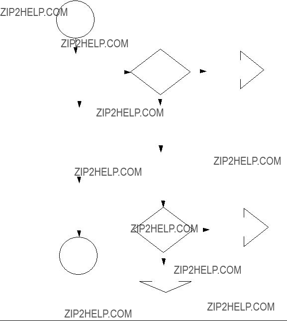
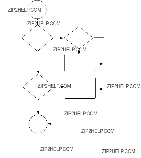
Diagnostic Flowcharts
Diagnostic Flowcharts
Table
Troubleshooting
Flowchart 1: Link Level Tests
Flowchart 1: Link Level Tests
Check communications between link levels on the source and target host using the linkloop , lanscan, and lanadmin commands. The source interface should be a VPPA, that is, a PPA corresponding to a VLAN interface. The destination MAC address is the remote VPPA???s MAC address.

Troubleshooting
Flowchart 1: Link Level Tests
Link Level
Tests
linkloop Test
lanscan and lanadmin Tests
Troubleshooting
Flowchart 1: Link Level Tests
Troubleshooting
Flowchart 1: Link Level Tests
Flowchart 1a Procedures
???Execute linkloop to remote host. If linkloop is successful, continue to Network Test. Else if linkloop fails note which error was returned.
???If loopback failed error = ???Address has bad format??? or ???not an individual address??? then correct the link level address with the proper station address format/value and repeat the Link Level Test.
???Otherwise, loopback failed because the remote host did not respond. Double check the remote host address and VLAN ID, or choose another remote host and
???Ensure VLAN IDs are the same by using lanadmin
???Ensure switches along the path are con???gured with the correct VLAN ID and marked ???tagged??? or ???untagged??? as appropriate.
???Ensure MTUs match as well.
???Ensure that link parameters for autonegotiation, ???ow control speed and duplexity are compatible.
???Ensure that the link is up. Refer to the documentation for each speci???c link for details.
If linkloop is successful, continue to Network Test. You may also want to contact the node manager of the remote that did not respond (if this was the case).

Troubleshooting
Flowchart 1: Link Level Tests
lanscan
and lanadmin
Test

Troubleshooting
Flowchart 1: Link Level Tests
Flowchart 1b Procedures
???Execute lanscan command and verify your interface is displayed by the system.
???If it is displayed, run lanscan
lanadmin
???If the interface is not displayed, run lanadmin
???If the problem is ???xed, Stop. Else, check for any error messages.
???If there are error messages correct them according to the error message.
???If there are no error messages, return to the network Test.

Troubleshooting
Flowchart 2: Network Level Tests
Network
Level
Tests
ARP Test
ping Test

Troubleshooting
Flowchart 2: Network Level Tests
Flowchart 2 Procedures
???See Flowchart 2a to validate ARP entries and remote host availability.
???See Flowchart 2b to check communication between network layers on source and target host using ping.
Troubleshooting
Flowchart 2: Network Level Tests
Flowchart 2a: ARP Test
ARP Test

Troubleshooting
Flowchart 2: Network Level Tests
Flowchart 2a Procedures
???Use ARP to verify that an entry exists for the remote host in your system's ARP cache by executing arp hostname
???If there is no ARP entry for the remote host, check to see if the remote host is up. If not, bring up remote host and continue to ping Test.
???If the ARP entry is incorrect or not complete, use ARP to enter the correct station address of the remote system and continue to ping Test. Otherwise, continue to ping Test.

Troubleshooting
Flowchart 2: Network Level Tests
Execute ping remotehost
YES

Troubleshooting
Flowchart 2: Network Level Tests
Flowchart 2b Procedures
???Execute ping to remote host using ping.
???If ping is successful, stop. If not, validate network, remote host, and con???guration settings. Verify the routing tables using the netstat

Troubleshooting
Flowchart 2: Network Level Tests
ping not successful
YES
Network
error?
NO
Call HP
ping
Test
Troubleshooting
Flowchart 2: Network Level Tests
Flowchart 2b (continued) Procedures
???If network unreachable error, go to the Con???guration Tests.
???If no response from ping, validate switches in path support VLANs and remote host supports them as well. Otherwise, recon???gure network path, or con???gure VLANs on remote host and/or switches then repeat ping Test. Return to linkloop test.
???If you receive an unknown hosts error, add the missing host name and repeat ping Test.
???If you receive ???error=SendTo: No route to host???, then using route add route table entry for the missing host and repeat ping Test. Otherwise, call HP.

Troubleshooting
NetTL Trace and Log of VLANs
NetTL Trace and Log of VLANs
The nettl tool can be used to troubleshoot VLANs. Following is a sample trace output from a Gigabit Ethernet card:
Tracing Output from a Gigabit Ethernet Card
^^^^^^^^^^^^^^^^^^^^^^Gigabit Ethernet LAN/9000 Networking^^^^^^^^^^^^^^^^^^
~~~~~~~~~~~~~~~~~~~~~~~~~~~~~~~~~~~~~~~~~~~~~~~~~~~~~~~~~~~~~~~~~~~~~~~~~~~~
=================================== Ethernet====================================
================================ IP Header (inbound
.........
.......
1424: 90 91 92 93 94 95 96 97 98 99
^^^^^^^^^^^^^^^^^^^^^^Gigabit Ethernet LAN/9000 Networking^^^^^^^^^^^^^^^^^^

~~~~~~~~~~~~~~~~~~~~~~~~~~~~~~~~~~~~~~~~~~~~~~~~~~~~~~~~~~~~~~~~~~~~~~~~~~~~
Logging Example
If you try to create a VLAN with a VLANID that is already present on the physical PPA you get the following output in verbose formatting mode:
*********************************VLAN Subsystem*****************************
~~~~~~~~~~~~~~~~~~~~~~~~~~~~~~~~~~~~~~~~~~~~~~~~~~~~~~~~~~~~~~~~~~~~~~~~~~~
<2003> Create: User specified VLANID 53 is already in use by another VLAN. (Error) The VLANID specified is already in use by another
VLAN created on the same physical interface(PPA). Choose another VLANID or try creating the VLAN on another physical interface(PPA).

Troubleshooting
NetTL Trace and Log of VLANs

Glossary
802.1p: IEEE Standard supplement, now incorporated in IEEE 802.1D. De???nes 8 priority levels for traf???c classi???cation at the data link level and suggests how they might be used.
802.1Q: IEEE Standard that speci???es the architecture for VLAN tagging, association, and
Alias: Name of the interface that corresponds to a given Internet address on a system.
Canonical format indicator: The CFI bit indicates that all MAC addresses present in the MAC data ???eld are in canonical
Card Instance Number: A number that uniquely identi???es a device within a class. A class of devices is a logical grouping of similar devices.
CoS: Class of Service. The ability to provide different levels of service to various traf???c ???ows. A ???ow may be determined explicitly via tags or implicitly from the frame contents (such as the IP address or ToS ???eld). Class of Service (CoS) network management is when similar types of traf???c (for example, voice, video, or data) are grouped together and assigned a priority. Unlike Quality of Service (QoS) traf???c management, CoS does not guarantee a level of service in terms of bandwidth and delivery time.
Destination Address: A ???eld in the message packet format identifying the end node(s) to which the packet is being sent.
Ethernet: A 10 Mbit/s LAN, developed by Digital Equipment Corporation, Intel, and Xerox Corporation, upon which the IEEE 802.3 network is based.
Fast Ethernet: A commonly used name applied to
HSC: High speed connect bus.
Hardware Path: An identi???er assigned by the system according to the physical location (slot) of a card in the hardware backplane.
Hostname: Name of system on the network.
Hub: A network interconnection device that allows multiple devices to share a single logical link segment. Hubs are generally either 10 Mbit/s or 100 Mbit/s devices.
IEEE: The Institute of Electrical and Electronics Engineers. A national association, whose activities include publishing standards applicable to various electronic technologies. The IEEE technical committees are numbered and grouped by area. For example, the 800 committees study local area network technologies. The 802.3 committee produced the standard for a CSMA/CD local area network, which has been adopted by ANSI.
Internet Address: The network address of a computer node. This address identi???es both which network the host is on and which host it is. Refer to the Installing and Administering LAN/9000 Software manual for detailed information about network addressing.

Glossary
IP:
IP: Internet protocol.
IP Address: See Internet Address glossary entry.
LAN: See Local Area Network.
Local Area Network (LAN): A data communications system that allows a number of independent devices to communicate with each other.
Local Network: The network to which a node is directly attached.
Maximum Transmission Unit (MTU).
Largest amount of data that can be transmitted through that interface. This value does not include the LLC or MAC headers.
NetTL. HP???s tracing and logging facility for
Network Interface: A communication path through which messages can be sent and received. A hardware network interface has a hardware device associated with it, such as a LAN card. A software network interface does not include a hardware device, for example the loopback interface. For every IP address instance, there must be one network interface con???gured.
NIC: Network interface card.
PCI: Peripheral component interconnect.
PPA: Physical point of attachment. A PPA is the point at which a system is attached to a physical communications medium. All communication on that physical medium funnels through the PPA.
QoS: Quality of Service. The ability to provide guarantees for data transfer
SAM: System admin manager.
Shared media LAN: A local area network (LAN) that shares all its bandwidth among all stations.
Switch: A network interconnection device that allows multiple connected senders and receivers to communicate simultaneously in contrast to a hub (repeater) where only one device can send at a time. Some switches have ???xed port speeds (10 Mbit/s or 100 Mbit/s) while others allow port speeds to be con???gured or autonegotiated.
Tag aware: Devices such as switches, routers, and
TCP: Transmission control protocol.
Topology: The physical and logical geometry governing placement of nodes in a computer network. Also, the layout of the transmission medium for a network.
ToS: IPv4 Type of Service ???eld which indicates the desired service expected by an IP packet for delivery through routers across the IP internetwork. The size of this ???eld is 8 bits, which contain bits for precedence, delay, throughput, and reliability characteristics.
UTP (Unshielded Twisted Pair) Cabling: A data cable type consisting of pairs of wires twisted together without an electrically shielding jacket.

Glossary
VPPA:
Virtual PPA or VPPA: Virtual Interfaces which are dynamically created by you (using lanadmin or SAM). The interfaces are ???virtual??? because they do not have a unique hardware instance. A virtual PPA is the PPA associated with a VLAN.
VLAN: Virtual LAN.VLANs, are a mechanism to determine which end stations should receive broadcast traf???c, since it should not be sent arbitrarily to every connected user. Each packet transmitted by an
VLAN ID: A VLAN ID uniquely identi???es the VLAN to which a frame belongs.
VLAN tag: A
VPPA: see Virtual PPA.

Glossary
Virtual PPA or VPPA: