Installation and
Getting Started Guide
ProCurve Series 5400zl Switches
PoE
Power over Ethernet Devices
www.procurve.com
Installation and
Getting Started Guide
ProCurve Series 5400zl Switches
PoE
Power over Ethernet Devices
www.procurve.com

ProCurve Series 5400zl Switches
Installation and Getting Started Guide

?? Copyright 2005 - 2007
This document contains proprietary information, which is protected by copyright. No part of this document may be photocopied, reproduced, or translated into another language without the prior written consent of
Publication Number
Applicable Products
Disclaimer
OF ANY KIND WITH REGARD TO THIS MATERIAL,
INCLUDING, BUT NOT LIMITED TO, THE IMPLIED
WARRANTIES OF MERCHANTABILITY AND FITNESS FOR A PARTICULAR PURPOSE.
The only warranties for HP products and services are set forth in the express warranty statements accompanying such products and services. Nothing herein should be construed as constituting an additional warranty. HP shall not be liable for technical or editorial errors or omissions contained herein.
Warranty
See the Customer Support/Warranty booklet included with the product.
A copy of the specific warranty terms applicable to your
Safety
Before installing and operating these products, please read the ???Installation Precautions??? in chapter 2, ???Installing the Series 5400zl Switches???, and the safety statements in appendix C, ???Safety and Regulatory Statements???.
8000 Foothills Boulevard, m/s 5552 Roseville, California

Contents
1Introducing the ProCurve Series 5400zl Switches
Front of the Switch . . . . . . . . . . . . . . . . . . . . . . . . . . . . . . . . . . . . . . . . . . . . . .
LEDs . . . . . . . . . . . . . . . . . . . . . . . . . . . . . . . . . . . . . . . . . . . . . . . . . . . . . .
LED Mode Select Button and Indicator LEDs . . . . . . . . . . . . . . . . . . . .
Console Port . . . . . . . . . . . . . . . . . . . . . . . . . . . . . . . . . . . . . . . . . . . . . .
Reset Button . . . . . . . . . . . . . . . . . . . . . . . . . . . . . . . . . . . . . . . . . . . . . .
Clear Button . . . . . . . . . . . . . . . . . . . . . . . . . . . . . . . . . . . . . . . . . . . . . . .
Back of the Switch . . . . . . . . . . . . . . . . . . . . . . . . . . . . . . . . . . . . . . . . . . . . .
Power Connector . . . . . . . . . . . . . . . . . . . . . . . . . . . . . . . . . . . . . . . . . .
Redundant Power Supply . . . . . . . . . . . . . . . . . . . . . . . . . . . . . . . . . . . .
Switch Features . . . . . . . . . . . . . . . . . . . . . . . . . . . . . . . . . . . . . . . . . . . . . . .
2 Installing the Series 5400zl Switches
Included Parts . . . . . . . . . . . . . . . . . . . . . . . . . . . . . . . . . . . . . . . . . . . . . . . . . .
Installation Procedures . . . . . . . . . . . . . . . . . . . . . . . . . . . . . . . . . . . . . . . . . .
Summary . . . . . . . . . . . . . . . . . . . . . . . . . . . . . . . . . . . . . . . . . . . . . . . . . . .
5.Mount the Switch . . . . . . . . . . . . . . . . . . . . . . . . . . . . . . . . . . . . . . . . .
. . . . . . . . . . . . . . . . . . . . . . . . . . . . . . . . . . . . . . . . . . . . . . . . . . . . . .
6. Install the Grounding Wire . . . . . . . . . . . . . . . . . . . . . . . . . . . . . . . . .
7. Connect the Switch to a Power Source . . . . . . . . . . . . . . . . . . . . . .
iii

8. (Optional) Connect a Power Supply Shelf
to the switch . . . . . . . . . . . . . . . . . . . . . . . . . . . . . . . . . . . . . . . . . . . . .
EPS Operation . . . . . . . . . . . . . . . . . . . . . . . . . . . . . . . . . . . . . . . . .
Operating Characteristics of the EPS (J8714A) . . . . . . . . . . . . . .
Power Supply Shelf LEDs . . . . . . . . . . . . . . . . . . . . . . . . . . . . . . . .
Connecting the Power Supply Shelf . . . . . . . . . . . . . . . . . . . . . . .
9. Connect the Network Devices . . . . . . . . . . . . . . . . . . . . . . . . . . . . . .
Hot Swapping Switch Modules . . . . . . . . . . . . . . . . . . . . . . . . . . . . . . . . . . .
Adding or Replacing Modules . . . . . . . . . . . . . . . . . . . . . . . . . . . . . . . .
Example Network Topologies . . . . . . . . . . . . . . . . . . . . . . . . . . . . . . . . . . .
Basic Connectivity . . . . . . . . . . . . . . . . . . . . . . . . . . . . . . . . . . . . . . . . .
Use as an Edge Switch . . . . . . . . . . . . . . . . . . . . . . . . . . . . . . . . . . . . . .
3 Getting Started With Switch Configuration
Recommended Minimal Configuration . . . . . . . . . . . . . . . . . . . . . . . . . .
Using the Switch Setup Screen . . . . . . . . . . . . . . . . . . . . . . . . . . . . . . . .
Where to Go From Here . . . . . . . . . . . . . . . . . . . . . . . . . . . . . . . . . . . . . .
Using the IP Address for Remote Switch Management . . . . . . . . . . . . . . . .
Starting a Telnet Session . . . . . . . . . . . . . . . . . . . . . . . . . . . . . . . . . . . . .
Starting a Web Browser Session . . . . . . . . . . . . . . . . . . . . . . . . . . . . . . .
Replacing Power Supplies . . . . . . . . . . . . . . . . . . . . . . . . . . . . . . . . . . . . . . . .
Replacing Fan Trays . . . . . . . . . . . . . . . . . . . . . . . . . . . . . . . . . . . . . . . . . . . . .
Replacing the Management Module . . . . . . . . . . . . . . . . . . . . . . . . . . . . . . . .
Replacing the Management Module Compact Flash Card . . . . . . . . . . . . .
Installing a Compact Flash Card . . . . . . . . . . . . . . . . . . . . . . . . . . . . . . .
Replacing the Management Module Battery . . . . . . . . . . . . . . . . . . . . . . . . .
Installing a New Battery . . . . . . . . . . . . . . . . . . . . . . . . . . . . . . . . . . . . . .
iv

Diagnosing with the LEDs . . . . . . . . . . . . . . . . . . . . . . . . . . . . . . . . . . . . . . . .
Proactive Networking . . . . . . . . . . . . . . . . . . . . . . . . . . . . . . . . . . . . . . . . . . .
Hardware Diagnostic Tests . . . . . . . . . . . . . . . . . . . . . . . . . . . . . . . . . . . . . .
Testing
Testing
Testing
Restoring the Factory Default Configuration . . . . . . . . . . . . . . . . . . . . . . .
Downloading New Code . . . . . . . . . . . . . . . . . . . . . . . . . . . . . . . . . . . . . . . .
HP Customer Support Services . . . . . . . . . . . . . . . . . . . . . . . . . . . . . . . . . .
Before Calling Support . . . . . . . . . . . . . . . . . . . . . . . . . . . . . . . . . . . . . .
Physical . . . . . . . . . . . . . . . . . . . . . . . . . . . . . . . . . . . . . . . . . . . . . . . . . . .
Environmental . . . . . . . . . . . . . . . . . . . . . . . . . . . . . . . . . . . . . . . . . . . . .
Acoustic . . . . . . . . . . . . . . . . . . . . . . . . . . . . . . . . . . . . . . . . . . . . . . . . . .
Switch 5400zl and
Switch 5412zl and
Network Connectors . . . . . . . . . . . . . . . . . . . . . . . . . . . . . . . . . . . . . . . .
B Switch Ports and Network Cables
Switch Ports . . . . . . . . . . . . . . . . . . . . . . . . . . . . . . . . . . . . . . . . . . . . . . .
Twisted Pair . . . . . . . . . . . . . . . . . . . . . . . . . . . . . . . . . . . . . . . . . . .
v

Cables . . . . . . . . . . . . . . . . . . . . . . . . . . . . . . . . . . . . . . . . . . . . . . . . . . . .
Copper Cables . . . . . . . . . . . . . . . . . . . . . . . . . . . . . . . . . . . . . . . . .
10 Mbps or 100 Mbps Network Connections . . . . . . . . . . . . . . . . . . . .
Crossover
10 Mbps or 100 Mbps Network Connection . . . . . . . . . . . . . . . . . . . . .
1000 Mbps Network Connections . . . . . . . . . . . . . . . . . . . . . . . . . . . .
C Safety and Regulatory Statements
Informations concernant la s??curit?? . . . . . . . . . . . . . . . . . . . . . . . . . . . . . .
Hinweise zur Sicherheit . . . . . . . . . . . . . . . . . . . . . . . . . . . . . . . . . . . . . . . . .
Safety Information (Japan) . . . . . . . . . . . . . . . . . . . . . . . . . . . . . . . . . . . . . .
Safety Information (China) . . . . . . . . . . . . . . . . . . . . . . . . . . . . . . . . . . . . . .
EMC Regulatory Statements . . . . . . . . . . . . . . . . . . . . . . . . . . . . . . . . . . . . .
U.S.A. . . . . . . . . . . . . . . . . . . . . . . . . . . . . . . . . . . . . . . . . . . . . . . . . . . . .
vi
1
Introducing the ProCurve Series
5400zl Switches
The ProCurve Series 5400zl Switches include the Switch 5406zl, 5412zl and their bundles, the Switch
Figure

Introducing the ProCurve Series 5400zl Switches
Figure

Introducing the ProCurve Series 5400zl Switches
Switch 5412zl, Switch
Figure

Introducing the ProCurve Series 5400zl Switches
Figure
See ???Switch Features??? on page
Introducing the ProCurve Series 5400zl Switches
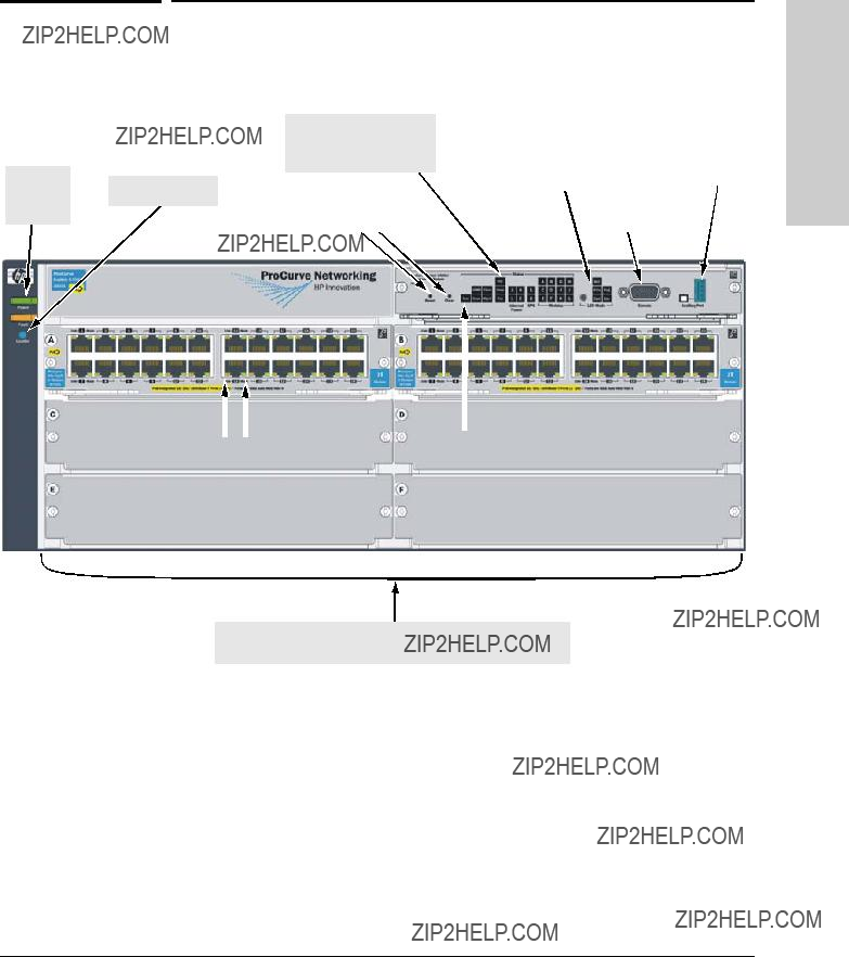
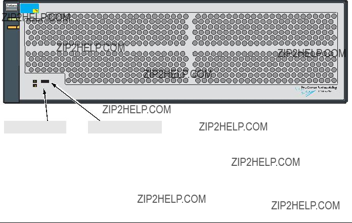
Front of the Switch
Front of the Switch
Status LEDs for the Fans, Power Supplies, and Switch Modules
Power
Switch Modules and slots
with Link and Mode LEDs for each port located on each module
Figure
This illustration shows the

Introducing the ProCurve Series 5400zl Switches
Front of the Switch


Introducing the ProCurve Series 5400zl Switches
Front of the Switch
1 The blinking behavior is an on/off cycle once every 1.6 seconds, approximately.
Introducing the ProCurve Series 5400zl Switches
Front of the Switch
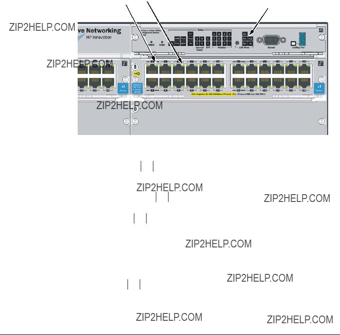
LED Mode Select Button and Indicator LEDs
To optimize the amount of information that can be displayed for each of the switch ports, the Series 5400zl Switches use a Mode LED for each port. The operation of this LED is controlled by the LED Mode Select button on the switch chassis, and the current selection is indicated by the mode indicator LEDs near the button. Press the button to change from one mode to the next.
Figure
???If the Activity Act indicator LED is lit, each port Mode LED displays activity information for the
???If the Full Duplex FDx indicator LED is lit, the port Mode LEDs light for those ports that are operating in full duplex.
???If the speed Spd indicator LED is lit, the port LEDs behave as follows to indicate the connection speed for the port:
???Off = 10 Mbps
???Blinking = 100 Mbps (the blinking behavior is a repeated on/off cycle once every 0.5 sec.)
???On = 1000 Mbps
???If the PoE PoE indicator LED is lit, the Link and Mode LEDs indicate PoE status:
Link LED:
???On = PoE is enabled on this port
???Off = PoE is disabled on this port.

Introducing the ProCurve Series 5400zl Switches
Front of the Switch
???Slow Blinking = Internal PoE fault on this port.
???Fast Blinking = This port is denied PoE power or has an external load fault.
Mode LED:
???On = PoE power is be supplied on this port
???Off = PoE is not being supplied on this port.
Console Port
This port is used to connect a console to the switch by using the serial cable supplied with the switch. This connection is described under ???Connecting a Console to the Switch??? in chapter 2, ???Installing the Series 5400zl Switches???. The console is a
Reset Button
This button will reset the switch when powered on. This action clears any temporary error conditions that may have occurred, executes the switch self test, and resets all network activity counters to zero. The counters are displayed in the switch console interface, the switch web browser interface, and through SNMP network management applications, such as ProCurve Manager.
Press the Reset button also after changing the module type that is installed in any of the switch module slots while the switch is powered on. In this case, the switch must be reset to initialize the new module type. See ???Hot Swapping Switch Modules??? on page
Clear Button
This button is used for the following purposes:
???Deleting Passwords - When pressed by itself for at least one second, the Clear button deletes any switch console access passwords that you may have configured. Use this feature if you have misplaced the password and need console access.
This button is provided for your convenience, but its presence means that if you are concerned with the security of the switch configuration and operation, you should make sure the switch is installed in a secure location, such as a locked wiring closet.
Introducing the ProCurve Series 5400zl Switches
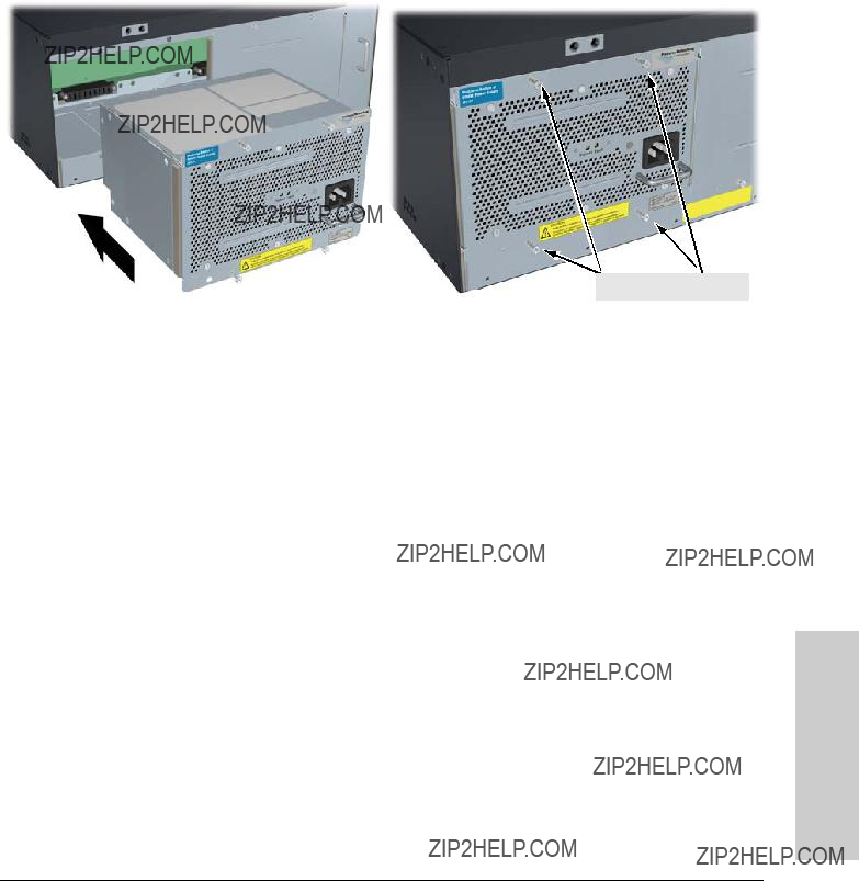
Back of the Switch
???Restoring Factory Default Configuration - When pressed with the Reset button in a specific pattern, the Clear button clears any configura- tion changes you may have made through the switch console, the web browser interface, or SNMP management, and restores the factory default configuration to the switch. For the specific method to restore the factory default configuration, see ???Restoring the Factory Default Configuration??? in chapter 4, ???Troubleshooting??? of this manual.
Back of the Switch
.
AC power connector
Grounding lug
 mounting holes
Slot for installing optional redundant power supply
Power and Fault LEDs
Figure
External PoE power connectors
Figure

Introducing the ProCurve Series 5400zl Switches
Back of the Switch
Power Connector
The Series 5400zl Switches do not have a power switch; they are powered on when connected to an active AC power source. The Series 5400zl Switches automatically adjust to any voltage between
Because the switch can run on a single supply, removing a redundant supply will not interrupt switch operation. However, on the 5412zl one power supply will only supply enough power to run the module slots
???ProCurve Switch zl Internal Power Supply Installation Guide.
???ProCurve Power over Ethernet (PoE) for zl and yl Products Planning and Implementation Guide.

Introducing the ProCurve Series 5400zl Switches
Switch Features
Switch Features
The features of the Series 5400zl Switches include:
???6 or 12 slots for installing any of the available Switch zl Modules. Supported Modules: As of this printing, the supported zl modules include:
???
???
???
???
???
???
???
???
???
???10
???10
???10
???10
???10
???
???the modules can be installed in any order and in any combination and can be ???hot swapped???.
???the supported
???high
???

Introducing the ProCurve Series 5400zl Switches
Switch Features
???automatic learning of the network addresses in the switch???s 16,000- address forwarding table, with configurable address aging value.
???
???easy management of the switch through several available interfaces:
???web browser
???console
???ProCurve
???Supported by ProCurve Network
???support for the Spanning Tree Protocol to eliminate network loops.
???support for up to 256 IEEE
???Layer 3 routing functionality:
???IP static routes
???RIP V1 and V2
???IRDP - ICMP Router Discovery Protocol
???OSPF- Open Shortest Path First
???DHCP relay
???support for many other advanced features to enhance network perfor- mance, security, and control??? for a description, see the Management and Configuration Guide which is on the ProCurve Web site. See page
???The auxiliary port is reserved for future development.
???Support for IEEE 802.3af standard and
2
Installing the Series 5400zl Switches
The Series 5400zl Switches are easily installed. They come with an accessory kit that includes the brackets for mounting the switch in a standard
Included Parts
The Series 5400zl Switches have the following components shipped with them:
???ProCurve Series 5400zl Switches Installation and Getting Started Guide, this manual
???ProCurve Manager - CD ROM and booklet
???Customer Support/Warranty booklet
???Accessory kits
5406zl Accessory Kit
two mounting brackets
eight 10 mm M4 screws to attach the mounting brackets to the switch
four
5412zl Accessory Kit
two mounting brackets - these brackets are twice as long as the brackets for the 5406zl switches
eight 10 mm M4 screws to attach the mounting brackets to the switch
four
???Console cable
???Power cord, one of the following:

Installing the Series 5400zl Switches
Included Parts
J a p a n P o w e r
C o r d W a r n i n g

N o t e
Installing the Series 5400zl Switches
Installation Procedures
Installation Procedures
Summary
Follow these easy steps to install your switch. The rest of this chapter provides details on these steps.
1.Prepare the installation site (page
2.Install switch modules (page
Make sure you use only ProCurve Switch zl Modules in your Series 5400zl Switches.
3.Install power supplies (page
4.Verify the switch passes self test (page
5.Mount the switch (page
6.Install the Grounding Wire (page

Installing the Series 5400zl Switches
Installation Procedures
7.Connect the switch to a power source (page
8.Connect a Power Supply Shelf
9.Connect the network devices (page
10.Connect a console to the switch
At this point, the switch is fully installed. See the rest of this chapter if you need more detailed information on any of these installation steps.


Installing the Series 5400zl Switches
Installation Procedures
Installing the Series 5400zl Switches
Installation Procedures
1. Prepare the Installation Site
Cabling Infrastructure
Ensure the cabling infrastructure meets the necessary network specifications. See the following table for cable types and lengths, and see appendix B, ???Switch Ports and Network Cables??? on page
Table
Category 5 or better,
100 meters
Note: The ProCurve
The Auto
Fiber Optic Cables
Note:

Installing the Series 5400zl Switches
Installation Procedures
Length Limits
???62.5 ??m cable:
???160 Mhz/km =
???200 Mhz/km =
???50 ??m cable:
???400 Mhz/km =
Installation Location
Before installing the switch, plan its location and orientation relative to other devices and equipment:
???In the front of the switch, allow at least 7.6 cm (3 inches) of space for the
???In the back of the switch, allow at least 10.2 cm (4 inches) of space for the power cord and cooling.
???On the sides of the switch, leave at least 7.6 cm (3 inches) for cooling.
C a u t i o n
M o d u l e
I n s t a l l a t i o n N o t e s
Installing the Series 5400zl Switches
Installation Procedures
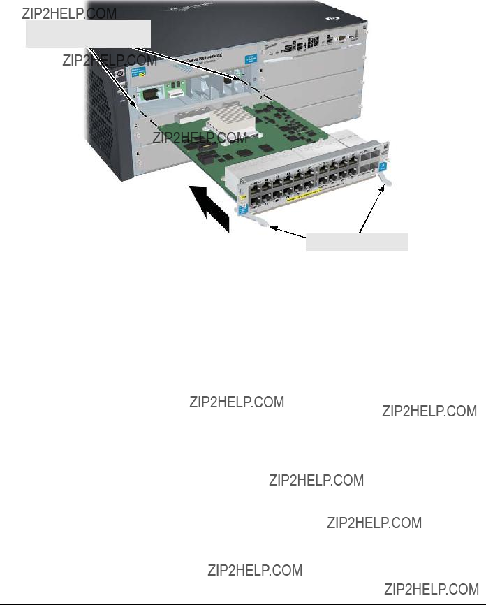
2. Install Switch Modules
Install switch modules into the slots as shown in the illustration below. For installation details, see the instructions in the manual that comes with the module.
Make sure you install only ProCurve Switch zl Modules.
Avoid any electrostatic discharge problems by handling the modules only by their bulkheads.
The slot cover can be removed, and the module can be installed with either a
???Any of the supported Switch zl Modules can be installed in any of the slots.
???The modules can be ???hot swapped???, installed after the switch is already powered on, and normally will be immediately operational. But, if you are replacing a module with a different type than what was previously installed in the slot, the switch must be rebooted after the module is installed. See ???Hot Swapping the Switch Module??? on page
???Ensure you fully insert the modules. That is, press the module into the slot using the extractor handles, until the bulkhead on the module is contacting the front face of the switch chassis.
???Once the module is fully inserted, screw in the two retaining screws to secure the module in place. The screws should be tightened until they are secure, but not overtightened.
???If you do not use one or more of the slots, ensure the slot cover plate is still attached over the slot for safe operation and proper switch cooling. For safety, you should not have more than one module slot uncovered at a time.
???Although these procedures show the
Installing the Series 5400zl Switches
Installation Procedures
Insert module into the guides and slide it in until it is fully inserted.
Open extractor handles
Figure

Installing the Series 5400zl Switches
Installation Procedures
Use the extractor handles to seat the module completely.
Then tighten the retaining screws on the module until they are secure, but do not overtighten them.
Figure

Installing the Series 5400zl Switches
Installation Procedures
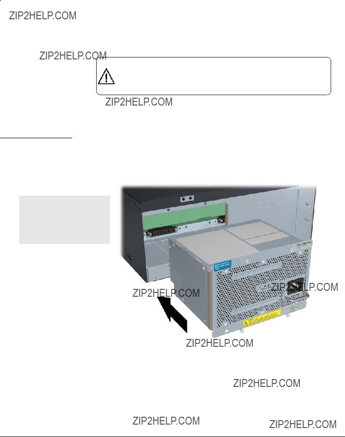
For safety and proper switch cooling, if either of the power supply slots are not being used, make sure to attach the cover plate over the slot. Please see the ???Installation Precautions??? on page
For installation details, see the instructions in the manual that comes with the power supply.
Insert the power supply into the opening, then slide it all the way in until it connects to the switch. The power supply face plate will be flush with the back face of the switch.
Figure
Installing the Series 5400zl Switches
Installation Procedures
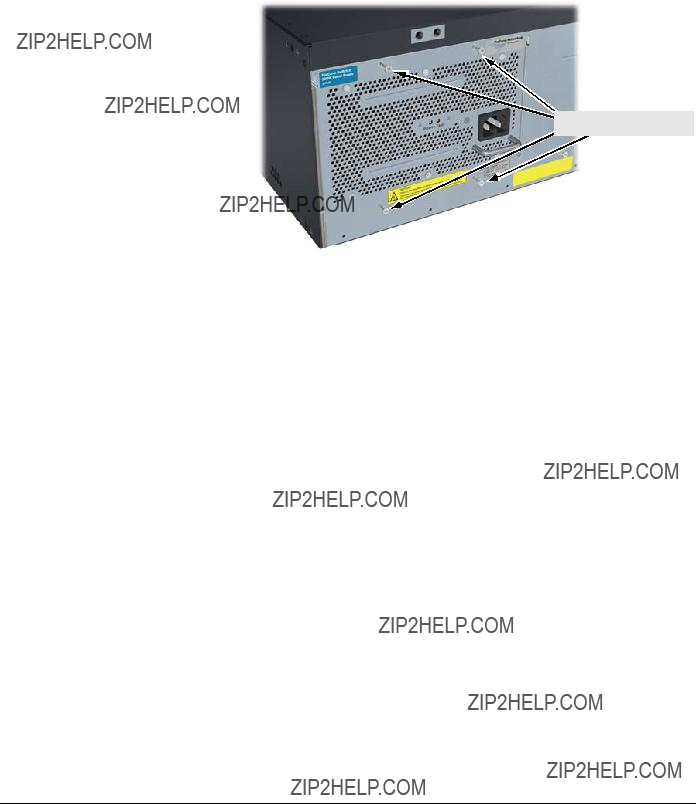
Once the power supply is installed, tighten the four retaining screws that hold it in place. The screws can be tightened with either a
tighten the four screws
Figure

Installing the Series 5400zl Switches
Installation Procedures
4. Verify the Switch Passes Self Test
After you have installed any modules and the optional second power supply, but before mounting the switch in its network location, you should first verify it is working properly by plugging it into a power source and verifying it passes its self test.
If you have installed a second power supply, repeat these procedures with the second power supply to verify it works correctly also.
1.Connect the power cord supplied with the switch to the power connector on the back of the switch, and then into a properly grounded electrical outlet.

Installing the Series 5400zl Switches
Installation Procedures
Figure
When the switch is powered on, it performs its diagnostic self test. The entire download, initialization, and self test process can take up to 2 minutes for a fully loaded chassis, depending on the number and type of modules installed in the switch.
LED Behavior:
During the self test:
???Initially, Power, Fault, Locator, and all the switch chassis LEDs are on. Then, after approximately 30 seconds, all the module LEDs go on as the modules receive power and code is downloaded to them, the Fault LED goes off, and the chassis LEDs turn orange and then go off except Test, Fan, and Power, which turn green.
???When the download of code to the modules is completed, the module LEDs go off. You may see each port LED go on briefly, in sequence, as the port is tested.
???For the duration of the self test, the Test LED stays on.
When the test completes successfully:
???The Power LED stays on, and the Status LEDs on the switch chassis stay on for the devices installed: one for each switch module installed, one for each power supply installed, and one for all the fans.
???The Fault, Locator, and Test LEDs are off.
???The port LEDs on the switch modules go into their normal operational mode:
E q u i p m e n t C a b i n e t
N o t e
W A R N I N G
Installing the Series 5400zl Switches
Installation Procedures
???If the ports are connected to active network devices, the Link LEDs stay on and the Mode LEDs behave according to the mode selected. In the default mode (Activity), the Mode LEDs should flicker showing network activity on the port.
???If the ports are not connected to active network devices, the LEDs will stay off.
5.Mount the Switch
After the modules and optional power supply are installed and you have verified the switch passes self test, you are ready to mount the switch in a stable location. The Series 5400zl Switches can be mounted in these ways:
???in a rack or cabinet
???on a horizontal surface
Rack or Cabinet Mounting
The Series 5400zl Switches are designed to be mounted in any
If you are installing the switch in an equipment cabinet, in place of the
For safe operation, please read the ???Installation Precautions??? on page
1.Use a #1 Phillips
For the Switch 5406zl, each bracket is attached with four screws as shown in the following illustration.
Although these procedures show the

Installing the Series 5400zl Switches
Installation Procedures
8 mm
M4 screws
Figure
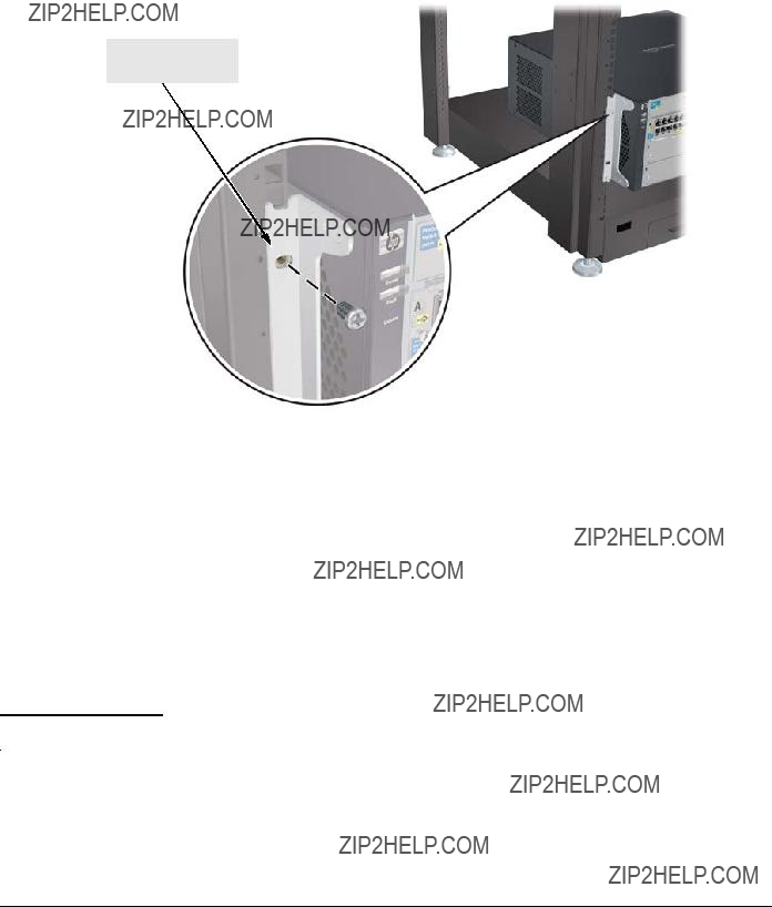
2.Partially install a screw into the top hole of a pair of holes that are 0.5 inches apart in each rack/cabinet upright as shown in the illustration below. Ensure that the screws are at the same level in each upright.
Partially install a screw into the top hole of a close
Figure
3.Place the switch in the rack and lower it so the notches in the bottom of the bracket slide onto the screws, then tighten these screws.

Installing the Series 5400zl Switches
Installation Procedures
lower the switch with mounting brackets onto the partially installed screws, then tighten these screws
Figure
Installing the Series 5400zl Switches
Installation Procedures
4.Install the other screw into the upper hole in each bracket. Tighten these screws.
install and tighten the other
Figure
Horizontal Surface Mounting
Place the switch on a table or other horizontal surface. Use a sturdy surface in an uncluttered area. You may want to secure the networking cables and switch power cord to the table legs or other part of the surface structure to help prevent people from tripping over the cords.

Installing the Series 5400zl Switches
Installation Procedures
6. Install the Grounding Wire
If a grounding wire is to be attached to the switch chassis, the grounding lug must be removed and a wire crimped to it and the grounding lug must be reinstalled.
1.Use a #1 Phillips
2.Crimp the grounding lug to a properly grounded grounding wire.
3.
Grounding lug
Grounding  lug screws
Figure
7. Connect the Switch to a Power Source
1.Plug the included power cord into the switch???s power connector and into a nearby properly grounded AC power source.
If a redundant power source is available, it is desirable to power one switch power supply from the regular AC source, and the other power supply from the redundant AC source. This will provide redundancy in AC power to the switch, as long as the switch PoE power usage falls within the capability of one power supply. If both power supplies are plugged into a common AC source, there is still power supply redundancy, that is, protection against power supply failure, but if the AC source fails, the switch will lose all power.
2.

Installing the Series 5400zl Switches
Installation Procedures
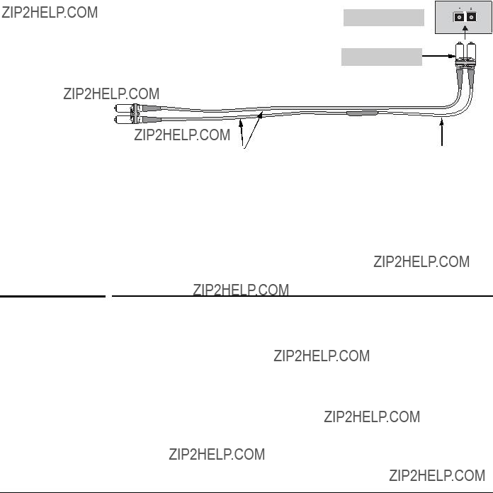
8. (Optional) Connect a Power Supply Shelf
to the switch
1. Connect the supplied external power supply (EPS) cables to the switch and to the Power Supply Shelf.
2. Tighten the thumb screws on all connectors to prevent any accidental disconnects.
3. Plug the power supply cords into the power connector and into a nearby properly grounded AC power source.
Installing the Series 5400zl Switches
Installation Procedures
Operating Characteristics of the EPS (J8714A)
The Power Supply Shelf has two EPS Ports. The EPS can provide a maximum of up to 900 watts of PoE power to each of the two EPS ports depending on which power supply is used. It is important to understand the PoE power requirements of the 5400zl Series switches because if the PoE power is not planned and implemented correctly the end devices connected to the switch ports may not receive power if an internal switch PoE power supply should fail. For further information regarding the Power Supply Shelf PoE capabilities, see the ProCurve Power over Ethernet (PoE) for zl and yl Products Planning and Implementation Guide and the ProCurve Power Supply Shelf Installation and Getting Started Guide, which is on the ProCurve Web site. See page
Power Supply Shelf LEDs
The EPS LEDs are duplicated on the front and back of the device. The following graphic shows an example of the front of the EPS. There are two dual colored (green/orange) LEDs for each EPS port:
???Device Connected
???Power Status
ProCurve Switch zl
Power Supply Shelf
J8714A PoE
E1 E2


Power Status LEDsDevice Connected LEDs

Installing the Series 5400zl Switches
Installation Procedures
Connecting the Power Supply Shelf
To Power
Source
5406zl
EPS Cables
Figure
5406zl
EPS Cables
To Power
Source
5406zl
Figure
Although these examples show the EPS connecting to the 5406zl switch, it can also be connected to a 5412zl switch in the same manner. These examples also show the switch and the EPS using the J8713A power supply, the J8712A power supply can also be used. It depends on how much PoE power is required.
For more information on PoE requirements see the Power over Ethernet (PoE) for zl and yl Products, Planning and Implementation Guide.

Installing the Series 5400zl Switches
Installation Procedures

Installing the Series 5400zl Switches
Installation Procedures
10. (Optional) Connect a Console to the Switch
The Series 5400zl Switches have a
???Monitor switch and port status and observe network activity counters
???Modify the switch???s configuration
???Read the event log and access diagnostic tools to help in troubleshooting
???Download new software to the switch
???Add passwords and other security features to control access to the switch from the console, web browser interface, and network management stations
The console can be accessed through these methods:
???
???
The Series 5400zl Switches can simultaneously support one
Terminal Configuration
To connect a console to the switch, configure the PC terminal emulator as a
???any baud rate from 2400 to 115200 (the switch automatically senses the speed)
???8 data bits, 1 stop bit, no parity, and flow control set to None
???for Windows Terminal program, also disable (uncheck) the ???Use Function, Arrow, and Ctrl Keys for Windows??? option
???for the Hilgrave HyperTerminal program, select the ???Terminal keys??? option for the ???Function, Arrow, and Ctrl keys act as??? parameter
If you want to operate the console using a different configuration, ensure you change the settings on both the terminal and on the switch. Change the switch settings first, then change the terminal settings, and reestablish the console session.
Installing the Series 5400zl Switches
Installation Procedures
Direct Console Access
To connect a console to the switch, follow these steps:
1.Connect the PC or terminal to the switch???s Console Port using the console cable included
with the switch. (If your PC or terminal has a 25- pin serial connector, first attach a
2.Turn on the terminal or PC???s power and, if using a
PC, start the PC terminal program.
3.Press the Enter key two or three times and you
will see the copyright page and the message ???Press any key to
continue???. Press a key, and you will then see the switch console CLI prompt.
Telnet Console Access
To access the switch through a telnet session, follow these steps:
1.Ensure the switch is configured with an IP address and that the switch is reachable from the telnet workstation (for example by using a Ping command to the switch???s IP address)
2.Start the telnet program and connect to the switch???s IP address.
3.The copyright page and the message ???Press any key to continue??? will display. Press a key, and the switch console CLI prompt will display.
If you want to continue with console management of the switch at this time through either a direct connection or a telnet session, see chapter 3, ???Getting Started With Switch Configuration??? for some basic configuration steps. For more detailed information, refer to the Management and Configuration Guide which is on the ProCurve Web site. See page

Installing the Series 5400zl Switches
Hot Swapping Switch Modules
Hot Swapping Switch Modules
The switch modules can be ???hot swapped??? (except for the Management Module, it is not hot swappable), that is installed or replaced while the switch is powered on (See Module Installation Notes on page
Adding or Replacing Modules
If a module has to be replaced with one of the same type, or you are expanding the switch capability by adding a module in a slot where one was not previ- ously installed (since the last switch reboot), the replaced or new module is immediately operational; there is no interruption to the switch operation.
Changing the Module Type
If you exchange a module with a different type of module though, for example a
You can reboot the switch by any of the following methods:
???Pressing the Reset button on the front of the switch.
???Unplugging and plugging in the power cord (power cycle). If two power supplies are installed, both power cords would have to be unplugged.
???Issuing the boot command from the switch console CLI, or selecting the boot Switch option from the switch console menu, the web browser interface, or ProCurve Manager.
Until the switch is rebooted, the module will not operate and the Module
Status LED for the affected slot will continue to flash.

Installing the Series 5400zl Switches
Example Network Topologies
Example Network Topologies
This section shows a few example network topologies in which the Series 5400zl Switches can be implemented. Although these examples show the
Basic Connectivity
Series 5400zl Switch
Phones, APs and other peripherals
Figure
The Series 5400zl Switches can provide basic network connectivity to a high number of PoE devices. These devices can be easily connected, as shown in the above illustration.

Installing the Series 5400zl Switches
Example Network Topologies
Use as an Edge Switch
Figure
When your network expands and the users need to access resources beyond the edge of the local network, the Series 5400zl Switches are excellent platforms for that expansion. With the flexibility of 6 slots, the high port count
In the above illustration, two Switch 5406zls are connected to a ProCurve
Routing Switch 9308, which can serve as a campus backbone or core switch.
The 1000 Mbps
The connections are trunked, through a configuration change on the Switch 5406zl, to provide redundancy and load sharing for higher bandwidth.

3
Getting Started With Switch Configuration
This chapter is a guide for using the console Switch Setup screen to quickly assign an IP (Internet Protocol) address and subnet mask to the switch, set a Manager password, and, optionally, configure other basic features.
For more information on using the switch console and the other switch management interfaces: the web browser interface and the SNMP manage- ment tool, ProCurve Manager, please see the Management and Configuration Guide which is on the ProCurve Web site. See page
Recommended Minimal Configuration
In the factory default configuration, the switch has no IP (Internet Protocol) address and subnet mask, and no passwords. In this state, it can be managed only through a direct console connection. To manage the switch through in- band (networked) access, you should configure the switch with an IP address and subnet mask compatible with your network. Also, you should configure a Manager password to control access privileges from the console and web browser interface. Other parameters in the Switch Setup screen can be left at their default settings or you can configure them with values you enter.
Many other features can be configured through the switch???s console interface, to optimize the switch???s performance, to enhance your control of the network traffic, and to improve network security. Once an IP address has been config- ured on the switch, these features can be accessed more conveniently through a remote Telnet session, through the switch???s web browser interface, and from an SNMP network management station running a network management program, such as ProCurve Manager. For a listing of switch features available with and without an IP address, refer to ???How IP Addressing Affects Switch Operation??? in the Management and Configuration Guide which is on the ProCurve Web site. See page
For more information on IP addressing, refer to ???IP Configuration??? in the
Management and Configuration Guide.
Switch With Started Getting
Configuration

Getting Started With Switch Configuration
Using the Switch Setup Screen
The quickest and easiest way to minimally configure the switch for manage- ment and password protection in your network is to use a direct console connection to the switch, start a console session, and access the Switch Setup screen.
1. Using the method described in the preceding section, connect a terminal device to the switch and display the switch console command (CLI) prompt (the default display).
The CLI prompt appears displaying the switch model number, for example:
ProCurve 5400zl#
2. At the prompt, enter the setup command to display the Switch Setup screen. The following illustration is an example of a Setup screen with default settings.
TIMEP
TimeP Mode [Disabled] : Disabled
Figure
Getting Started With Switch Configuration
3.Use the Tab key to select the Manager Password field and enter a manager password of up to 16 characters.
4.Tab to the IP Config (DHCP/Bootp) field and use the Space bar to select the Manual option.
5.Tab to the IP Address field and enter the IP address that is compatible with your network.
6.Tab to the Subnet Mask field and enter the subnet mask used for your network.
7.Press Enter, then S (for Save).
The following is information on the fields in the Setup screen. For more information on these fields, see the Management and Configuration Guide which is on the ProCurve Web site. See page
Note: The IP address and subnet mask assigned for the switch must be compatible with the IP addressing used in your network. For more information on IP addressing, see the Management and Configuration Guide which is on
the ProCurve Web site. See page
Switch With Started Getting
Configuration

Getting Started With Switch Configuration
Where to Go From Here
The above procedure configures your switch with a Manager password, IP address, and subnet mask. As a result, with the proper network connections, you can now manage the switch from a PC equipped with Telnet, a web browser interface, or from an
Some basic information on managing your switch is included in the next section. For more information on the console, web browser, and SNMP management interfaces and all the features that can be configured on the Series 5400zl Switches, please see the Management and Configuration Guide which is on the ProCurve Web site. See page
To Recover from a Lost Manager Password: If you cannot start a con- sole session at the manager level because of a lost Manager password, you can clear all passwords and user names by getting physical access to the switch and pressing and holding the Clear button for a full second.
Getting Started With Switch Configuration
Using the IP Address for Remote Switch Management
Using the IP Address for Remote Switch Management
With your Series 5400zl Switches, you can use the switch???s IP address to manage the switch from any PC that is on the same subnet as the switch. You can use either a Telnet session or a standard web browser to manage the switch.
Starting a Telnet Session
To access the switch through a Telnet session, follow these steps:
1.Ensure the switch is configured with an IP address and that the switch is
reachable from the PC that is running the Telnet session (for example, by using a ping command to the switch???s IP address).
2.Start the Telnet program on a PC that is on the same subnet as the switch and connect to the switch???s IP address.
3.You will see the copyright page and the message ???Press any key to continue???. Press a key, and you will then see the switch console command (CLI) prompt, for example (assuming there is no password):
ProCurve 5400zl#
Enter help or ? to see a list of commands that can be executed at the prompt. Entering any command followed by help provides more detailed context help information about the command. Entering any command followed by ? displays a list of options that are available at that point in the command entry.
Starting a Web Browser Session
Your Series 5400zl Switch can be managed through a graphical interface that you can access from any PC or workstation on the network by running your web browser and typing in the switch???s IP address as the URL. No additional software installation is required to make this interface available; it is included in the switch???s onboard software.
An example web browser interface screen is shown in the next illustration.
Switch With Started Getting
Configuration

Getting Started With Switch Configuration
Using the IP Address for Remote Switch Management
ProCurve Switch 5406zl - Status:xl Information
J8699A ProCurve Switch 5406zlxl l
P oE Status
Figure
For more information on using the web browser interface, please see the
Management and Configuration Guide which is on the ProCurve Web site. See page
An extensive help system is also available for the web browser interface. To access the help system though, the subnet on which the switch is installed must have access to the internet, or ProCurve Manager needs to be installed on a network management station that is on the subnet.
4
Replacing Components
H o t S w a p p i n g
C a u t i o n
This chapter shows you how to remove and install the following components:
???Power supplies (see page
???Management module (see page
???Management module components Flash Disk (see page
For a complete list of parts and part numbers, see page
The ProCurve Switch 5400zl supports ???hot swapping??? - the ability to replace the following hardware components while the switch is operating: a fan tray, power supply (if a second power supply is installed), interface module.
The Management module and its components are not hot swappable.
The hot swapping feature allows you to remove or install modules without powering off or rebooting the switch.
The ProCurve 5400zl Switch and its components are sensitive to static discharge. Use an antistatic wrist strap and observe all static precautions when hot swapping components. For example, connect your antistatic wrist strap to the ground point on the front of the switch, above the rightmost power supply bay.
Components Replacing

Replacing Components
Replacing Components
Replacing Power Supplies
Replacing Power Supplies
If your ProCurve 5400zl Switch is configured with redundant power supplies, you will not suffer any loss of traffic or performance if a power supply fails. Replace the failed component as soon as possible. One of the Internal Power LEDs on the management module will blink simultaneously with the switch Fault LED indicating which power supply failed.
Although these procedures show the
To remove an AC power supply:
1.Ensure the AC power supply is not plugged into an AC power source on the failed power supply.
2.Using either a
Figure
Replacing Components
Replacing Power Supplies
3.Insert the power supply into the opening. Slide it all the way in until it connects to the switch. The power supply face plate will be flush with the back face of the switch.
tighten the four screws
Figure
4.Tighten the four retaining screws that hold it in place. Be careful not to overtighten the screws.
For more detail refer to the ProCurve Switch zl Internal Power Supply Installation Guide
Components Replacing

Replacing Components
Replacing Fan Trays
To replace a fan tray:
1.Using either a
2.Install the new fan tray assembly and tighten the retaining screws.
Replacing Components
Figure

Replacing Components
Replacing the Management Module
Replacing the Management Module
The switch does not have to be powered off to remove the management module, however when the management module is removed all ports will lose communication. ProCurve Networking recommends replacing the Manage- ment module, flash disk and battery (on the Management module) during scheduled down time.
To install (or replace) a Management Module:
1.On the module unscrew the retaining screws enough to disconnect them from the threaded holes in the switch.
2.Using the extractor handles, pull the module out from the slot.
3.Remove the flash disk from the failed module and install it into the replacement module.
4.Remove the battery from the failed module and dispose of properly.
5.Install the new battery that came with the replacement module. See the following pages for replacement instructions.
6.Install the replacement module into the switch.
7.Use an equal amount of pressure and push both extractor handles closed to completely seat the module.
8.Tighten the retaining screws.
Retaining Screws
Extractor Handles
Components Replacing
Replacing Components
Replacing Components
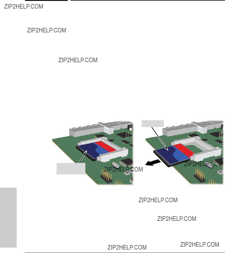
Replacing the Management Module Compact Flash Card
Replacing the Management Module
Compact Flash Card
The Compact Flash card is the primary
Installing a Compact Flash Card
To install (or replace) a Compact Flash card:
1.Using either a
2.Using the extractor handles, pull the management module out from the slot.
Slide out
CompactFlash
Memory disk
Figure
3.Slide out the old flash card.
4.Slide in the new flash card being careful not to bend any pins.
5.Reinstall the management module into the switch.
6.Use an equal amount of pressure and push both extractor handles closed to completely seat the module.
7.Tighten the retaining screws.
Replacing Components
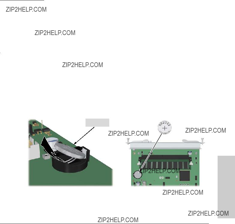
Replacing the Management Module Battery
Replacing the Management Module Battery
The battery on the management module is used to keep time for the internal switch clock. There is no indicator LED for when the battery dies. The only indication will be the internal clock will not keep the correct time.
Installing a New Battery
To install (or replace) a New Battery:
1. Using either a
2. Using the extractor handles, pull the module out from the slot.
Battery
Figure
Components Replacing

Replacing Components
Replacing the Management Module Battery
Mettre au rebut les batteries usag??es conform??ment aux instructions du fabricant.
Replacing Components
5
Troubleshooting
This chapter describes how to troubleshoot your Series 5400zl Switches. Note that this document describes troubleshooting mostly from a hardware perspective. You can perform more
Technical support
Product manuals (all)
ProCurve Switch 3500yl or 6200yl Series.
(You may want to bookmark this Web page for easy access in the future.)
This chapter describes the following:
???basic troubleshooting tips (page
???diagnosing with the LEDs (page
???Proactive Networking tools (page
???hardware diagnostic tests (page
???restoring the factory default configuration (page
???downloading new code (page
???HP Customer Support Services (page
Basic Troubleshooting Tips
Most problems are caused by the following situations. Check for these items first when starting your troubleshooting:
???Faulty or loose cables. Look for loose or obviously faulty connections. If they appear to be OK, make sure the connections are snug. If that does not correct the problem, try a different cable.
Troubleshooting
Troubleshooting
Troubleshooting
Basic Troubleshooting Tips
???
???Improper Network Topologies. It is important to make sure you have a valid network topology. Common topology faults include excessive cable length and excessive repeater delays between end nodes. If you have network problems after recent changes to the network, change back to the previous topology. If you no longer experience the problems, the new topology is probably at fault.
In addition, you should make sure that your network topology contains no data path loops. Between any two end nodes, there should be only one active cabling path at any time. Data path loops will cause broadcast storms that will severely impact your network performance.
With your Series 5400zl Switches, if you wish to build redundant paths between important nodes in your network to provide some fault toler- ance, you should enable Spanning Tree Protocol support on the switch. This ensures that only one of the redundant paths is active at any time, thus avoiding data path loops. Spanning Tree can be enabled through the switch console, the web browser interface, or ProCurve Manager.
The Series 5400zl Switches also support Trunking, which allows multiple network cables to be used for a single network connection without causing a data path loop. See the Management and Configuration Guide for more information on Spanning Tree and on Trunking, which is on the ProCurve Web site. See page
???Connecting to devices that have a fixed
The
???if the connected device is also configured to Auto, the switch will automatically negotiate both link speed and communication mode
???if the connected device has a fixed configuration, for example 100 Mbps, at half or full duplex, the switch will automatically sense the link speed, but will default to a communication of half duplex
Troubleshooting
Basic Troubleshooting Tips
Because the Series 5400zl Switches behave in this way (in compliance with the IEEE 802.3 standard), if a device connected to the switch has a fixed configuration at full duplex, the device will not connect correctly to the switch. The result will be high error rates and very inefficient communications between the switch and the device.
Ensure that all devices connected to the Series 5400zl Switches are configured to auto negotiate, or are configured to connect at half duplex (all hubs are configured this way, for example).
If necessary though, you can modify the configuration of the ports on the Series 5400zl Switches to match the configuration of the connected device. Use the switch console, the web browser interface, or ProCurve Manager to modify the port configuration.
???Check the port configuration. A port on your Series 5400zl Switch may not be operating as you expect because it has been put into a ???blocking??? state by Spanning Tree, GVRP (automatic VLANs), or LACP (automatic trunking). (Note that the normal operation of the Spanning Tree, GVRP, and LACP features may put the port in a blocking state.) Or, the port just may have been configured as disabled through software.
Use the switch console to determine the port???s configuration and verify that there is not an improper or undesired configuration of any of the switch features that may be affecting the port. See the Management and Configuration Guide which is on the ProCurve Web site. See page
For more information on possible network problems and their solutions, refer to the technical note ???Troubleshooting LAN Performance and Intermittent Connectivity Problems???, which can be found on the ProCurve Networking Web site, www.procurve.com, in the Reference Library section.
Troubleshooting
Troubleshooting
Troubleshooting
Diagnosing with the LEDs
Diagnosing with the LEDs
Table
1.Check in the table for the LED pattern you see on your switch
2.Refer to the corresponding diagnostic tip on the next few pages.
Table
1This LED is not important for the diagnosis.
2The blinking behavior is an on/off cycle once every 1.6 seconds, approximately.
3The fast blinking behavior is an on/off cycle once every 0.8 seconds, approximately

Troubleshooting
Diagnosing with the LEDs
Diagnostic Tips:
???The power supplies installed in the switch are not plugged into active AC power sources, or the power supply may have failed.
1.Verify the power cord is plugged into an active power source and to the switch. Ensure these connections are snug.
2.Try power cycling the switch by unplugging and plugging the power cord back in.
3.If the Power LED is still not on, verify the AC power source works by plugging another device into the outlet. Or try plugging the switch into a different outlet or try a different power cord.
If the power source and power cord are OK and this condition persists, the switch power supply may have failed. Call your ProCurve authorized LAN dealer, or use the electronic support services from ProCurve to get assistance. See the Customer Support/Warranty card for more information.
Troubleshooting
???The module installed in the slot that corresponds to the letter that is blinking is an invalid module.
The fact that the Link and Mode LEDs never are lit on the module indicates that it is a ProCurve Switch gl module and should not be used in your zl switch.
Ensure you have installed a zl module in the slot. ProCurve xl/gl modules Zl will fit in the slot, but they are not compatible with your ProCurve zl switch.
module Check to ensure the module has a Blue ???zl module??? symbol on it.
Remove the module from the switch and replace it with a zl module, or recover the slot with the cover plate. You can remove and replace the module without having to power down the switch. Call your ProCurve authorized LAN dealer, or use the electronic support services from ProCurve to get information on supported Switch zl modules. The modules that are available as of the printing of this manual are listed on page
Troubleshooting
Diagnosing with the LEDs
Troubleshooting
???The module installed in the slot that corresponds to the letter that is blinking has experienced a self test or initialization fault.
The modules are all tested whenever the switch is powered on, or reset (through the Reset button on the switch, or the Boot or Reset options in the console or web browser interface), and when they are hot swapped (installed when the switch is powered on).
Since the Link and Mode LEDs on the module were lit at least briefly, that indicates that the module did receive power from the switch, but the subsequent download process failed. Either the module is faulty, or it is a new module type that is not yet supported by the operating code on the switch.
As ProCurve Networking introduces new modules for your ProCurve Switch zl, you may have to update the switch with new operating code that supports the new module. The documentation that came with the module will indicate which version of the operating code is needed to support the module. The modules that are supported in your Switch zl, as of the printing of this manual, are listed on
page
First verify the switch has a version of code that supports the module that is indicating the fault. If the module is not one of the ones listed on page
If you have the correct code installed in the switch, try removing and reinstalling the module. You can do this without having to power down the switch. When the module is reinstalled, it will be retested automatically.
If the fault indication reoccurs, the module may have failed. Remove the module from the switch and replace it with another module, or recover the slot with the cover plate. Call your ProCurve authorized LAN dealer, or use the electronic support services from ProCurve to get assistance. See the Customer Support/Warranty card for more information.
???In the slot corresponding to the letter that is blinking, a module was installed that is a different type than the previously installed module, and the switch has not yet been reset.
When you ???hot swap??? modules in the switch slots, if you install a different module type than the one that was previously installed in the slot, you must reset the switch so the switch processor can properly initialize and configure the new module type. The blinking LED informs you that this change of module types has occurred. The module will not work properly until the switch is reset.
You can reset the switch by any of these methods:
???pressing the Reset button.
???power cycling the switch.
???selecting the reset or reboot option from the console, web browser interface, or ProCurve Manager.
Troubleshooting
Diagnosing with the LEDs
???The network port for which the Link LED is blinking has experienced a self test or initialization failure.
During the module self test, described in tip number 4 earlier in this table, each network port is also tested. If the port self test fails, the individual port is not usable, but the rest of the ports on the module, which have passed their self test, will continue to operate normally.
If the port is a
To verify the port has failed, try removing and reinstalling the module, as described in tip number 4. For the
Troubleshooting
???A fault condition has been detected on the power supply installed in the slot corresponding to the blinking number.
Try removing and reinstalling the power supply.
Caution: Ensure the AC power cord is disconnected from the supply before removing and reinstalling the supply.
Reconnect the power supply to the AC power source. If the error indication reoccurs after the supply is reinstalled, the power supply may be faulty. Call your ProCurve authorized LAN dealer, or use the electronic support services from ProCurve Networking to get assistance. See the Customer Support/Warranty card for more information.
???One or more of the switch cooling fans may have failed.
Try disconnecting power from the switch and wait a few moments. Then reconnect the power to the switch and check the LEDs again. If the error indication reoccurs, one or more of the fans has failed. The switch has multiple fans and may continue to operate OK under this condition if the ambient temperature does not exceed normal room temperature, but for best operation, the switch should be replaced. Contact your ProCurve authorized LAN dealer, or use the electronic support services from ProCurve Networking to get assistance. See the Customer Support/ Warranty card for more information.
???The network port for which the Link LED is blinking has been disabled because port security has been configured on the switch and a security violation has been detected on the port.
For the Port Security feature, you can configure the switch so that whenever a security violation is detected on a port, the switch will disable the port. When a port is disabled by this feature, the port Link LED will be continuously flashed at the fast rate of 0.8 seconds per cycle. The blinking continues until you clear the security violation through the switch console. In the console, you can view the identity of the connected device that committed the security violation.
Once the security violation is cleared, you must
For more information on the Port Security feature, see the Management and Configuration Guide which is on the ProCurve Web site. See page
Troubleshooting
Diagnosing with the LEDs
Troubleshooting
The network connection is not working properly.
Try the following procedures:
???For the indicated port, verify both ends of the cabling, at the switch and the connected device, are securely connected.
???Verify the connected device and switch are both powered on and operating correctly.
???Verify you have used the correct cable type for the connection.
???for any of the
Note: If the module configuration is changed to one of the fixed configuration options though (for example,
???for
???For a 1000 Mbps connection, verify the network cabling complies with the IEEE 802.3ab standard. The cable should be installed according to the ANSI/TIA/EIA-
The cable verification must include all patch cables from any end devices, including the switch, to any patch panels in the cabling path.
???Verify the port has not been disabled through a switch configuration change.
You can use the console interface, or, if you have configured an IP address on the switch, use the web browser interface, or ProCurve Manager network management software to determine the state of the port and
???Verify the switch port configuration matches the configuration of the attached device. For example, if the switch port is configured as ???Auto???, the port on the attached device also MUST be configured as ???Auto???. Depending on the port type,
If the other procedures don???t resolve the problem, try using a different port or a different cable.

Troubleshooting
Proactive Networking
Proactive Networking
The Series 5400zl Switches have
???finding and helping you fix the most common network error conditions (for example, faulty network cabling, and
???informing you of the problem with clear,
???recommending network configuration changes to enhance the performance of your network
The following interfaces provide tests, indicators, and an event log that can be used to monitor the switch and its network connections, and to help you take advantage of these proactive networking features:
???ProCurve Manager - an
???A graphical web browser interface you can use to manage your switch from a PC that is running a supported web browser, for example Microsoft Internet Explorer or Netscape Communicator.
???A
See the ???Troubleshooting??? chapter in the Management and Configuration Guide for more information on using these software tools to diagnose and manage your switch, which is on the ProCurve Web site. See page
Troubleshooting

Troubleshooting
Troubleshooting
Hardware Diagnostic Tests
Hardware Diagnostic Tests
Testing the Switch by Resetting It
If you believe the switch is not operating correctly, you can reset the switch to test its circuitry and operating code. To reset a switch, either:
???Unplug and plug in the power cord (power cycling)
???Press the Reset button on the front of the switch
???Select the reset or reboot option from the console, web browser interface, or ProCurve Manager.
Power cycling the switch, pressing the Reset button, and the software reset or reboot options all cause the switch to perform its
Checking the Switch LEDs
The
See ???Diagnosing With the LEDs??? on page
Checking Console Messages
Useful diagnostic messages may be displayed on the console screen when the switch is reset. As described in chapter 2 under step 8, ???Connect a Console to the Switch???, connect a PC running a

Troubleshooting
Hardware Diagnostic Tests
Testing
If you think the cable should work but still isn???t working, it may not be compatible with the IEEE 802.3 Type
ProCurve Networking also offers a wire testing service. Contact your ProCurve authorized LAN dealer or your local ProCurve Networking sales office for more information.
Testing
You can perform the following communication tests to verify the network is operating correctly between the switch and any connected device that can respond correctly to the communication test.
???Link Test
???Ping Test
These tests can be performed through the switch console interface from a terminal connected to the switch or through a telnet connection, or from the switch???s web browser interface. See the Management and Configuration Guide which is on the ProCurve Web site. See page
These tests can also be performed from an SNMP network management station running a program that can manage the switch, for example, ProCurve Manager.
Testing
Both the switch and the cabling can be tested by running an
Troubleshooting
Troubleshooting
Troubleshooting
Restoring the Factory Default Configuration
Troubleshooting
Downloading New Code
Downloading New Code
When product enhancements occur for the Series 5400zl Switches, new code can be downloaded to the switch through several methods, for product enhancements and new features. Please see the Management and Configu- ration Guide which is on the ProCurve Web site. See page
The new code would be available on the ProCurve Networking Web site, www.procurve.com.
HP Customer Support Services
If you are still having trouble with your switch,
Additionally, your ProCurve authorized network reseller can provide you with assistance, both with services that they offer and with services offered by ProCurve Networking.
Before Calling Support
Before calling your networking dealer or ProCurve Support, to make the support process most efficient, retrieve the following information:
Troubleshooting
A
Specifications
Physical
Electrical
The Series 5400zl Switches automatically adjust to any voltage between
Each installed module may draw 369.6W@50V for PoE
Specifications
Specifications
Specifications
Environmental
1 If you are installing either the J8705A or J8707A modules, or any of the X2 transceivers, the operating ambient temperature should not exceed 40??C (104??F). See transceiver specifications below.
TRANSCEIVERS

Running H/F 1
Acoustic
Switch 5400zl and
Ger??uschemission LpA = 40.2 dB am fiktiven Arbeitsplatz nach DIN 45635 T.19
Noise Emission LpA = 40.2 dB in a virtual workspace according to DIN 45635 T.19
Switch 5412zl and
Ger??uschemission LpA = 45.8 dB am fiktiven Arbeitsplatz nach DIN 45635 T.19
Noise Emission LpA = 45.8 dB in a virtual workspace according to DIN 45635 T.19
Network Connectors
???The 10/100 Mbps
???The 100/1000 Mbps
???The 1000 Mbps
???The copper ports are compatible with the IEEE 802.1ak standards.
???The
???The console port is a standard
Safety
???EN60950
???CSA 22.2 No. 60950
???UL 60950
???IEC 60950
Specifications

Specifications
Lasers
The following products are Class 1 Laser Products.
???Laser Klasse 1:The
???The
???The
The following products are Class 1m Laser Products.
Laser Klasse 1m:
??? The
The transceivers comply with IEC 60825.
Specifications

B
Switch Ports and Network Cables
Switch Ports
Twisted Pair
??? The
??? The
??? The
??? The
Network and Ports Switch
Cables
Switch Ports and Network Cables
Cables
10 Mbps Operation Category 3, 4, or 5
100 Mbps Operation Category 5
1000 Mbps Operation Category 5
(See ???Note on
Note on
Because of the increased speed provided by
When testing your cabling, be sure to include the patch cables that connect the switch and other end devices to the patch panels on your site. The patch cables are frequently overlooked when testing cable and they must also comply with the cabling standards.

Switch Ports and Network Cables
OR
the multimode
Note: To use multimode cables for
Note: Between the transmit and receive ends of the cable, at least 5db of attenuation is required for a reliable connection. This is equivalent to 20Km of the
Network and Ports Switch
Cables

Switch Ports and Network Cables
Note: Conditioning patch cord cables are not supported for
Copper Cables
N o t e
N o t e
Switch Ports and Network Cables
Mode Conditioning Patch Cord for
Mode Conditioning Patch Cord for
The following information applies to installations in which multimode fiber- optic cables are connected to a
Mode Conditioning Patch Cord cables only apply to one Gigabit operation. Mode Conditioning Patch Cord cables are not supported for 10 Gigabit operation.
Unlike
If you experience a high number of transmission errors on the
The patch cord consists of a short length of
If you are using good quality
Network and Ports Switch
Cables
Switch Ports and Network Cables
Installing the Patch Cord
As shown in the illustration below, connect the patch cord to the
If you connect the patch cord directly to the network cabling, you may need to install a
LX connector
To network multimode cabling
Figure
Make sure you purchase a patch cord that has LC connectors on the end that connects to the
The HP

Other Wiring Rules:
???All
???For
???For 10 Mbps connections to the ports, you can use Category 3, 4, or 5
???For 100 Mbps connections to the ports, use Category 5
???For 1000 Mbps connections, Category 5 or better
Network and Ports Switch
Cables
Switch Ports and Network Cables
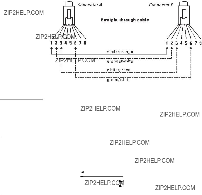
10 Mbps or 100 Mbps Network Connections
Because of the HP
If any of these ports are given a fixed configuration, for example 100 Mbps/ Full Duplex, the ports operate as
Cable Diagram
Figure
Switch Ports and Network Cables
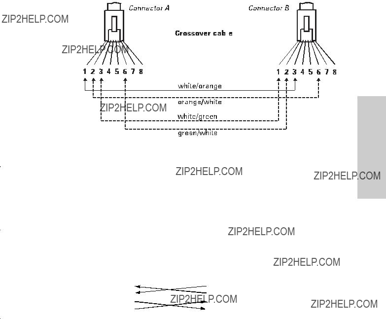
Crossover
10 Mbps or 100 Mbps Network Connection
The HP
If any of these ports are given a fixed configuration, for example 100 Mbps/ Full Duplex, the ports operate as
Cable Diagram
Network and Ports Switch
Cables
Switch Ports and Network Cables
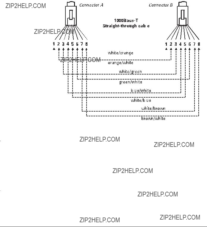
Cable Diagram
.
Pin Assignments
For

C
Safety and Regulatory Statements
Safety Information
!
WARNING
Caution
Grounding
Documentation reference symbol. If the product is marked with this symbol, refer to the product documentation to get more information about the product.
A WARNING in the manual denotes a hazard that can cause injury or death.
A Caution in the manual denotes a hazard that can damage equipment.
Do not proceed beyond a WARNING or Caution notice until you have understood the hazardous conditions and have taken appro- priate steps.
These are safety class I products and have protective earthing terminals. There must be an uninterruptible safety earth ground from the main power source to the product's input wiring terminals, power cord, or supplied power cord set. Whenever it is likely that the protection has been impaired, disconnect the power cord until the ground has been restored.
For LAN cable grounding:
???If your LAN covers an area served by more than one power distribu- tion system, be sure their safety grounds are securely interconnected.
???LAN cables may occasionally be subject to hazardous transient volt- ages (such as lightning or disturbances in the electrical utilities power grid). Handle exposed metal components of the network with Caution.
Servicing
There are no
These products do not have a power switch; they are powered on when the power cord is plugged in.
Regulatory and Safety
Statements
Safety and Regulatory Statements
Informations concernant la s??curit??
Informations concernant la s??curit??
!
WARNING
Caution
Symbole de r??f??rence ?? la documentation. Si le produit est marqu?? de ce symbole,
Dans la documentation, un WARNING indique un danger susceptible d'entra??ner des dommages corporels ou la mort.
Un texte de mise en garde intitul?? Caution indique un danger suscep- tible de causer des dommages ?? l'??quipement.
Ne continuez pas
Cet appareil est un produit de classe I et poss??de une borne de mise ?? la terre. La source d'alimentation principale doit ??tre munie d'une prise de terre de s??curit?? install??e aux bornes du c??blage d'entr??e, sur le cordon d'alimentation ou le cordon de raccordement fourni avec le produit. Lorsque cette protection semble avoir ??t?? endommag??e, d??brancher le cordon d'alimentation jusqu'?? ce que la mise ?? la terre ait ??t?? r??par??e.
Mise ?? la terre du c??ble de r??seau local:
???si votre r??seau local s'??tend sur une zone desservie par plus d'un syst??me de distribution de puissance,
???Les c??bles de r??seaux locaux peuvent occasionnellement ??tre soumis ?? des surtensions transitoires dangereuses (telles que la foudre ou des perturba- tions dans le r??seau d'alimentation public). Manipulez les composants m??talliques du r??seau avec pr??cautions.
Aucune pi??ce contenue ?? l'int??rieur de ce produit ne peut ??tre r??par??e par l'utilisateur. Tout d??pannage, r??glage, entretien ou r??paration devra ??tre confi?? exclusivement ?? un personnel qualifi??.
Cet appareil ne comporte pas de commutateur principal ; la mise sous tension est effectu??e par branchement du cordon d'alimentation.
Statements
Safety and Regulatory

Fahren Sie nach dem Hinweis WARNING oder Caution erst fort, nachdem Sie den Gefahrenzustand verstanden und die entsprech- enden Ma??nahmen ergriffen haben.
Dies ist ein Ger??t der Sicherheitsklasse I und verf??gt ??ber einen sch??tzenden Erdung- sterminal. Der Betrieb des Ger??ts erfordert eine ununterbrochene Sicherheitserdung von der Hauptstromquelle zu den Ger??teingabeterminals, den Netzkabeln oder dem mit Strom belieferten Netzkabelsatz voraus. Sobald Grund zur Annahme besteht, da?? der Schutz beeintr??chtigt worden ist, das Netzkabel aus der Wandsteckdose herausz- iehen, bis die Erdung wiederhergestellt ist.
F??r
???Wenn Ihr LAN ein Gebiet umfa??t, das von mehr als einem Stromverteilungs- system beliefert wird, m??ssen Sie sich vergewissern, da?? die Sicherheitserdungen fest untereinander verbunden sind.
???
Dieses Ger??t enth??lt innen keine durch den Benutzer zu wartenden Teile.
Dieses Ger??t hat keinen Netzschalter; es wird beim Anschlie??en des Netzkabels eingeschaltet.
Regulatory and Safety
Statements

Statements
Safety and Regulatory
Safety and Regulatory Statements
Considerazioni sulla sicurezza
Considerazioni sulla sicurezza
Questo prodotto ?? omologato nella classe di sicurezza I ed ha un terminale protettivo di collegamento a terra. Dev'essere installato un collegamento a terra di sicurezza, non interrompibile che vada dalla fonte d'alimentazione principale ai terminali d'entrata, al cavo d'alimentazione oppure al set cavo d'alimentazione fornito con il prodotto.
Ogniqualvolta vi sia probabilit?? di danneggiamento della protezione, disinserite il cavo d'alimentazione fino a quando il collegaento a terra non sia stato ripristinato.
Per la messa a terra dei cavi LAN:
???se la vostra LAN copre un'area servita da pi?? di un sistema di distribuzione elettrica, accertatevi che i collegamenti a terra di sicurezza siano ben collegati fra loro;
???i cavi LAN possono occasionalmente andare soggetti a pericolose tensioni transitorie (ad esempio, provocate da lampi o disturbi nella griglia d'alimen- tazione della societ?? elettrica); siate cauti nel toccare parti esposte in metallo della rete.
Nessun componente di questo prodotto pu?? essere riparato dall'utente. Qualsiasi lavoro di riparazione, messa a punto, manutenzione o assistenza va effettuato esclusi- vamente da personale specializzato.
Questo apparato non possiede un commutatore principale; si mette scotto tensione all'inserirsi il cavo d'alimentazione.
Safety and Regulatory Statements
Consideraciones sobre seguridad
Consideraciones sobre seguridad
Este aparato se enmarca dentro de la clase I de seguridad y se encuentra protegido por una borna de puesta a tierra. Es preciso que exista una puesta a tierra continua desde la toma de alimentaci??n el??ctrica hasta las bornas de los cables de entrada del aparato, el cable de alimentaci??n o el juego de cable de alimentaci??n suministrado. Si existe la probabilidad de que la protecci??n a tierra haya sufrido desperfectos, desenchufar el cable de alimentaci??n hasta haberse subsanado el problema.
Puesta a tierra del cable de la red local (LAN):
???Si la LAN abarca un ??rea cuyo suministro el??ctrico proviene de m??s de una red de distribuci??n de electricidad, cerciorarse de que las puestas a tierra est??n conectadas entre s?? de modo seguro.
???Es posible que los cables de la LAN se vean sometidos de vez en cuando a voltajes moment??neos que entra??en peligro (rayos o alteraciones en la red de energ??a el??ctrica). Manejar con precauci??n los componentes de metal de la LAN que est??n al descubierto.
Este aparato no contiene pieza alguna susceptible de reparaci??n por parte del usuario. Todas las reparaciones, ajustes o servicio de mantenimiento debe realizarlos sola- mente el t??cnico.
Este producto no tiene interruptor de potencia; se activa cuando se enchufa el cable
de alimentaci??n. Statements Safetyand Regulatory

Safety and Regulatory Statements
Safety Information (Japan)
Safety Information (Japan)
Statements
Safety and Regulatory
Safety and Regulatory Statements
Safety Information (China)
Safety Information (China)
Regulatory and Safety
Statements
Safety and Regulatory Statements
EMC Regulatory Statements
EMC Regulatory Statements
U.S.A.
FCC Class A
This equipment has been tested and found to comply with the limits for a Class A digital device, pursuant to Part 15 of the FCC Rules. These limits are designed to provide reasonable protection against interference when the equipment is operated in a commercial environment. This equipment gener- ates, uses, and can radiate radio frequency energy and, if not installed and used in accordance with the instruction manual, may cause interference to radio communications. Operation of this equipment in a residential area may cause interference in which case the user will be required to correct the interference at his own expense.
Canada
This product complies with Class A Canadian EMC requirements.
Australia/New Zealand
This product complies with Australia/New Zealand EMC Class A requirements.
Japan
VCCI Class A
Statements
Safety and Regulatory

Safety and Regulatory Statements
EMC Regulatory Statements
Korea
Taiwan
Regulatory Model Identification Number
For regulatory identification purposes, the ProCurve Series 5400zl Switches are assigned a Regulatory Model Number. The Regulatory Model Number for these switches is RSVLC- 0503.
This regulatory number should not be confused with the marketing name (ProCurve Series 5400zl Switches), or
product numbers (J8697A, J8698A, J8699A, and J8700A). Statements Safetyand Regulatory

Statements
Safety and Regulatory
Safety and Regulatory Statements
EMC Regulatory Statements
European Community
DECLARATION OF CONFORMITY
according to ISO/IEC Guide 22 and EN 45014
______________________________________________________________________
EN
EN
Supplementary Information:
The product herewith complies with the requirements of the Low Voltage Directive 73/23/EEC and the EMC Directive 89/336/EEC and carries the CE marking accordingly.
The product was tested with
Roseville, 30 Jan 2007
____________________________________
Michael E. Avery, Regulatory Engineering Mgr.
European Contact: Your local
TRE, Herrenberger Stra??e 140,

D
Recycle Statements
Waste Electrical and Electronic
Equipment (WEEE) Statements
Disposal of Waste Equipment by Users in Private Household in the European Union
This symbol on the product or on its packaging indicates that this product must not be disposed of with your other household waste. Instead, it is your responsibility to dispose of your waste equipment by handing it over to a designated collection point for the recycling of waste electrical and electronic equipment. The separate collection and recycling of your waste equipment at the time of disposal will help to conserve natural resources and ensure that it is recycled in a manner that protects human health and the environment. For more information about where you can drop off your waste equipment for recycling, please contact your local city office, your household waste disposal service or the shop where you purchased the product.
Likvidace za????zen?? soukrom??mi dom??c??mi u??ivateli v Evropsk?? unii
Tento symbol na produktu nebo balen?? ozna??uje v??robek, kter?? nesm?? b??t vyhozen spolu s ostatn??m dom??c??m odpadem. Povinnost?? u??ivatele je p??edat takto ozna??en?? odpad na p??edem ur??en?? sb??rn?? m??sto pro recyklaci elektrick??ch a elektronick??ch za????zen??. Okam??it?? t????d??n?? a recyklace odpadu pom????e uchovat p????rodn?? prost??ed?? a zajist?? takov?? zp??sob recyklace, kter?? ochr??n?? zdrav?? a ??ivotn?? prost??ed?? ??lov??ka. Dal???? informace o mo??nostech odevzd??n?? odpadu k recyklaci z??sk??te na p????slu??n??m obecn??m nebo m??stsk??m ????ad??, od firmy zab??vaj??c?? se sb??rem a svozem odpadu nebo v obchod??, kde jste produkt zakoupili.
Bortskaffelse af affald fra husstande i den Europ??iske Union
Hvis produktet eller dets emballage er forsynet med dette symbol, angiver det, at produktet ikke m?? bortskaffes med andet almindeligt husholdningsaffald. I stedet er det dit ansvar at bortskaffe kasseret udstyr ved at aflevere det p?? den kommunale genbrugsstation, der forest??r genvinding af kasseret elektrisk og elektronisk udstyr. Den centrale modtagelse og genvinding af kasseret udstyr i forbindelse med bortskaffelsen bidrager til bevarelse af naturlige ressourcer og sikrer, at udstyret genvindes p?? en m??de, der beskytter b??de mennesker og milj??. Yderligere oplysninger om, hvor du kan aflevere kasseret udstyr til genvinding, kan du f?? hos kommunen, den lokale genbrugsstation eller i den butik, hvor du k??bte produktet.
Seadmete j????tmete k??rvaldamine eramajapidamistes Euroopa Liidus
See tootel v??i selle pakendil olev s??mbol n??itab, et k??nealust toodet ei tohi koos teiste majapidamisj????t- metega k??rvaldada. Teie kohus on oma seadmete j????tmed k??rvaldada, viies need elektri- ja elektrooni- kaseadmete j????tmete ringlussev??tmiseks selleks etten??htud kogumispunkti. Seadmete j????tmete eraldi kogumine ja ringlussev??tmine k??rvaldamise ajal aitab kaitsta loodusvarasid ning tagada, et ringlussev- ??tmine toimub viisil, mis kaitseb inimeste tervist ning keskkonda. Lisateabe saamiseks selle kohta, kuhu oma seadmete j????tmed ringlussev??tmiseks viia, v??tke palun ??hendust oma kohaliku linnakantselei, majapidamisj????tmete k??rvaldamise teenistuse v??i kauplusega, kust Te toote ostsite.
Statements Recycle
Recycle Statements
Recycle Statements
Waste Electrical and Electronic Equipment (WEEE) Statements
Laitteiden h??vitt??minen kotitalouksissa Euroopan unionin alueella
Jos tuotteessa tai sen pakkauksessa on t??m?? merkki, tuotetta ei saa h??vitt???? kotitalousj??tteiden mukana. T??ll??in h??vitett??v?? laite on toimitettava s??hk??laitteiden ja elektronisten laitteiden kierr??tyspisteeseen. H??vitett??vien laitteiden erillinen k??sittely ja kierr??tys auttavat s????st??m????n luonnonvaroja ja varmistamaan, ett?? laite kierr??tet????n tavalla, joka est???? terveyshaitat ja suojelee luontoa. Lis??tietoja paikoista, joihin h??vitett??v??t laitteet voi toimittaa kierr??tett??v??ksi, saa ottamalla yhteytt?? j??tehuoltoon tai liikkeeseen, josta tuote on ostettu.
??limination des appareils mis au rebut par les m??nages dans l'Union europ??enne
Le symbole appos?? sur ce produit ou sur son emballage indique que ce produit ne doit pas ??tre jet?? avec les d??chets m??nagers ordinaires. Il est de votre responsabilit?? de mettre au rebut vos appareils en les d??posant dans les centres de collecte publique d??sign??s pour le recyclage des ??quipements ??lectriques et ??lectroniques. La collecte et le recyclage de vos appareils mis au rebut ind??pendamment du reste des d??chets contribue ?? la pr??servation des ressources naturelles et garantit que ces appareils seront recycl??s dans le respect de la sant?? humaine et de l'environnement. Pour obtenir plus d'informations sur les centres de collecte et de recyclage des appareils mis au rebut, veuillez contacter les autorit??s locales de votre r??gion, les services de collecte des ordures m??nag??res ou le magasin dans lequel vous avez achet?? ce produit.
Entsorgung von Altger??ten aus privaten Haushalten in der EU
Das Symbol auf dem Produkt oder seiner Verpackung weist darauf hin, dass das Produkt nicht ??ber den normalen Hausm??ll entsorgt werden darf. Benutzer sind verpflichtet, die Altger??te an einer R??cknah- mestelle f??r Elektro- und
???????????????? ???????????????? ???????????????????? ?????? ?????????????? ???? ???????????????? ???????????????????? ???????? ?????????????????? ??????????
???? ?????????????? ???????? ?????? ???????????? ?? ???? ???????????????????? ?????? ?????????????????????? ?????? ???? ???????????????????????? ???????????? ?????? ???????????? ???? ???????????????????? ???????? ???? ???? ???????? ?????????????? ?????? ??????????????????????. ????????????????, ?????????? ???????? ?????? ???????????? ???? ???????????????????? ?????? ?????????????? ?????????????????? ?????? ???????????????????????? ?????? ???? ?????????????????????? ???????????? ???????????????? ?????? ?????? ???????????????????? ???????????????? ???????????????????? ?????? ???????????????????????? ????????????????????. ?? ?????????????????? ?????????????? ?????? ???????????????????? ?????? ???????????????? ???????????????????? ?????? ???????? ?????? ???????????????? ???? ???????????????? ?????? ?????????????????? ?????? ?????????????? ?????????? ?????? ???? ?????????????????????? ?????? ?? ???????????????????? ?????????????? ???? ?????????? ?????? ?????????????????????? ?????? ?????????????????? ?????????? ?????? ???? ????????????????????. ?????? ???????????????????????? ?????????????????????? ?????????????? ???? ???? ?????? ???????????????? ???? ???????????????????? ?????? ?????????????? ?????????????????? ?????? ?????? ????????????????????, ?????????????????????????? ???? ???? ?????????????? ???????????? ??????????????, ?????? ???????????? ???????????????? ???????????????? ???????????????? ???????????????????????? ?? ???? ?????????????????? ???????? ?????????????????? ???? ????????????.
K??sz??l??kek mag??nh??ztart??sban t??rt??n?? selejtez??se az Eur??pai Uni?? ter??let??n
A k??sz??l??ken, illetve a k??sz??l??k csomagol??s??n l??that?? azonos szimb??lum annak jelz??s??re szolg??l, hogy a k??sz??l??k a selejtez??s sor??n az egy??b h??ztart??si hullad??kt??l elt??r?? m??don kezelend??. A v??s??rl?? a hullad??kk?? v??lt k??sz??l??ket k??teles a kijel??lt gy??jt??helyre sz??ll??tani az elektromos ??s elektronikai k??sz??l??kek ??jrahasznos??t??sa c??lj??b??l. A hullad??kk?? v??lt k??sz??l??kek selejtez??skori begy??jt??se ??s ??jrahasznos??t??sa hozz??j??rul a term??szeti er??forr??sok meg??rz??s??hez, valamint biztos??tja a selejtezett term??kek k??rnyezetre ??s emberi eg??szs??gre n??zve biztons??gos feldolgoz??s??t. A begy??jt??s pontos hely??r??l b??vebb t??j??koztat??st a lakhelye szerint illet??kes ??nkorm??nyzatt??l, az illet??kes szem??teltakar??t?? v??llalatt??l, illetve a term??ket el??rus??t?? helyen kaphat.

Recycle Statements
Waste Electrical and Electronic Equipment (WEEE) Statements
Smaltimento delle apparecchiature da parte di privati nel territorio dell'Unione Europea
Questo simbolo presente sul prodotto o sulla sua confezione indica che il prodotto non pu?? essere smaltito insieme ai rifiuti domestici. ?? responsabilit?? dell'utente smaltire le apparecchiature consegnan- dole presso un punto di raccolta designato al riciclo e allo smaltimento di apparecchiature elettriche ed elettroniche. La raccolta differenziata e il corretto riciclo delle apparecchiature da smaltire permette di proteggere la salute degli individui e l'ecosistema. Per ulteriori informazioni relative ai punti di raccolta delle apparecchiature, contattare l'ente locale per lo smaltimento dei rifiuti, oppure il negozio presso il quale ?? stato acquistato il prodotto.
Nolietotu iek??rtu izn??cin????anas noteikumi lietot??jiem Eiropas Savien??bas priv??taj??s m??jsaimniec??b??s
????ds simbols uz izstr??d??juma vai uz t?? iesai??ojuma nor??da, ka ??o izstr??d??jumu nedr??kst izmest kop?? ar citiem sadz??ves atkritumiem. J??s atbildat par to, lai nolietot??s iek??rtas tiktu nodotas speci??li iek??rtotos punktos, kas paredz??ti izmantoto elektrisko un elektronisko iek??rtu sav??k??anai otrreiz??jai p??rstr??dei. Atsevi????a nolietoto iek??rtu sav??k??ana un otrreiz??j?? p??rstr??de pal??dz??s saglab??t dabas resursus un garant??s, ka ????s iek??rtas tiks otrreiz??ji p??rstr??d??tas t??d?? veid??, lai pasarg??tu vidi un cilv??ku vesel??bu. Lai uzzin??tu, kur nolietot??s iek??rtas var izmest otrreiz??jai p??rstr??dei, j??v??r??as savas dz??ves vietas pa??vald??b??, sadz??ves atkritumu sav??k??anas dienest?? vai veikal??, kur?? izstr??d??jums tika nopirkts.
Vartotoj?? i?? priva??i?? nam?? ??ki?? ??rangos atliek?? ??alinimas Europos S??jungoje
??is simbolis ant gaminio arba jo pakuot??s rodo, kad ??io gaminio ??alinti kartu su kitomis nam?? ??kio atliekomis negalima. ??alintinas ??rangos atliekas privalote pristatyti ?? speciali?? surinkimo viet?? elektros ir elektronin??s ??rangos atliekoms perdirbti. Atskirai surenkamos ir perdirbamos ??alintinos ??rangos atliekos pad??s saugoti gamtinius i??teklius ir u??tikrinti, kad jos bus perdirbtos tokiu b??du, kuris nekenkia ??moni?? sveikatai ir aplinkai. Jeigu norite su??inoti daugiau apie tai, kur galima pristatyti perdirbtinas ??rangos atliekas, kreipkit??s ?? savo seni??nij??, nam?? ??kio atliek?? ??alinimo tarnyb?? arba parduotuv??, kurioje ??sigijote gamin??.
Verwijdering van afgedankte apparatuur door
Dit symbool op het product of de verpakking geeft aan dat dit product niet mag worden gedeponeerd bij het normale huishoudelijke afval. U bent zelf verantwoordelijk voor het inleveren van uw afgedankte apparatuur bij een inzamelingspunt voor het recyclen van oude elektrische en elektronische apparatuur. Door uw oude apparatuur apart aan te bieden en te recyclen, kunnen natuurlijke bronnen worden behouden en kan het materiaal worden hergebruikt op een manier waarmee de volksgezondheid en het milieu worden beschermd. Neem contact op met uw gemeente, het afvalinzamelingsbedrijf of de winkel waar u het product hebt gekocht voor meer informatie over inzamelingspunten waar u oude apparatuur kunt aanbieden voor recycling.
Pozbywanie si?? zu??ytego sprz??tu przez u??ytkownik??w w prywatnych gospodarstwach domowych w Unii Europejskiej
Ten symbol na produkcie lub jego opakowaniu oznacza, ??e produktu nie wolno wyrzuca?? do zwyk??ych pojemnik??w na ??mieci. Obowi??zkiem u??ytkownika jest przekazanie zu??ytego sprz??tu do wyznaczonego punktu zbi??rki w celu recyklingu odpad??w powsta??ych ze sprz??tu elektrycznego i elektronicznego. Osobna zbi??rka oraz recykling zu??ytego sprz??tu pomog?? w ochronie zasob??w naturalnych i zapewni?? ponowne wprowadzenie go do obiegu w spos??b chroni??cy zdrowie cz??owieka i ??rodowisko. Aby uzyska?? wi??cej informacji o tym, gdzie mo??na przekaza?? zu??yty sprz??t do recyklingu, nale??y si?? skontaktowa?? z urz??dem miasta, zak??adem gospodarki odpadami lub sklepem, w kt??rym zakupiono produkt.
Statements Recycle

Recycle Statements
Recycle Statements
Waste Electrical and Electronic Equipment (WEEE) Statements
Descarte de Lixo El??trico na Comunidade Europ??ia
Este s??mbolo encontrado no produto ou na embalagem indica que o produto n??o deve ser descartado no lixo dom??stico comum. ?? responsabilidade do cliente descartar o material usado (lixo el??trico),
Likvid??cia vyraden??ch zariaden?? v dom??cnostiach v Eur??pskej ??nii
Symbol na v??robku alebo jeho balen?? ozna??uje, ??e dan?? v??robok sa nesmie likvidova?? s domov??m odpadom. Povinnos??ou spotrebite??a je odovzda?? vyraden?? zariadenie v zbernom mieste, ktor?? je ur??en?? na recykl??ciu vyraden??ch elektrick??ch a elektronick??ch zariaden??. Separovan?? zber a recykl??cia vyraden??ch zariaden?? prispieva k ochrane pr??rodn??ch zdrojov a zabezpe??uje, ??e recykl??cia sa vykon??va sp??sobom chr??niacim ??udsk?? zdravie a ??ivotn?? prostredie. Inform??cie o zbern??ch miestach na recykl??ciu vyraden??ch zariaden?? v??m poskytne miestne zastupite??stvo, spolo??nos?? zabezpe??uj??ca odvoz domov??ho odpadu alebo obchod, v ktorom ste si v??robok zak??pili.
Odstranjevanje odslu??ene opreme uporabnikov v zasebnih gospodinjstvih v Evropski uniji
Ta znak na izdelku ali njegovi embala??i pomeni, da izdelka ne smete odvre??i med gospodinjske odpadke. Nasprotno, odslu??eno opremo morate predati na zbirali????e, poobla????eno za recikliranje odslu??ene elektri??ne in elektronske opreme. Lo??eno zbiranje in recikliranje odslu??ene opreme prispeva k ohranjanju naravnih virov in zagotavlja recikliranje te opreme na zdravju in okolju ne??kodljiv na??in. Za podrobnej??e informacije o tem, kam lahko odpeljete odslu??eno opremo na recikliranje, se obrnite na pristojni organ, komunalno slu??bo ali trgovino, kjer ste izdelek kupili.
Eliminaci??n de residuos de equipos el??ctricos y electr??nicos por parte de usuarios particulares en la Uni??n Europea
Este s??mbolo en el producto o en su envase indica que no debe eliminarse junto con los desperdicios generales de la casa. Es responsabilidad del usuario eliminar los residuos de este tipo deposit??ndolos en un "punto limpio" para el reciclado de residuos el??ctricos y electr??nicos. La recogida y el reciclado selectivos de los residuos de aparatos el??ctricos en el momento de su eliminaci??n contribuir?? a conservar los recursos naturales y a garantizar el reciclado de estos residuos de forma que se proteja el medio ambiente y la salud. Para obtener m??s informaci??n sobre los puntos de recogida de residuos el??ctricos y electr??nicos para reciclado, p??ngase en contacto con su ayuntamiento, con el servicio de eliminaci??n de residuos dom??sticos o con el establecimiento en el que adquiri?? el producto.
Bortskaffande av avfallsprodukter fr??n anv??ndare i privathush??ll inom Europeiska Unionen
Om den h??r symbolen visas p?? produkten eller f??rpackningen betyder det att produkten inte f??r sl??ngas p?? samma st??lle som hush??llssopor. I st??llet ??r det ditt ansvar att bortskaffa avfallet genom att ??verl??mna det till ett uppsamlingsst??lle avsett f??r ??tervinning av avfall fr??n elektriska och elektroniska produkter. Separat insamling och ??tervinning av avfallet hj??lper till att spara p?? v??ra naturresurser och g??r att avfallet ??tervinns p?? ett s??tt som skyddar m??nniskors h??lsa och milj??n. Kontakta ditt lokala kommunkontor, din n??rmsta ??tervinningsstation f??r hush??llsavfall eller aff??ren d??r du k??pte produkten f??r att f?? mer information om var du kan l??mna ditt avfall f??r ??tervinning.
Index
Numerics
connections, length limitations ???
connections, length limitations ???
connections, length limitations ???
connections, length limitations ???
ports, cables used with ???
ports, cables used with ???
A
auto
auxiliary or USB port location on switch ???
B
back of switch description ???
slot for redundant power supply ???
IP address ???
battery
replacing battery ???
error indications ???
automatic switch configuration ???
buttons
LED Mode Select button ???
C
cabinet
mounting the switch in ???
cables
cable specifications ???
note on cable requirements ???
cable specifications ???
cable specifications ???
Index
Index ??? 1

Index
cables, twisted pair category 3, 4, 5 ???
crossover cable
note on requirements for
cabling infrastructure ???
deleting passwords ???
location on switch ???
restoring factory default configuration ???
to delete password protection ???
displaying ???
checking when troubleshooting ???
IP address, manually ???
restoring factory defaults ???
connecting the switch to a power source ???
console
checking messages during troubleshooting ???
displaying the CLI prompt ???
how to connect
console port description ???
location on switch ???
use with fixed port configurations ???
D
deleting passwords ???
back of switches ???
DHCP
automatic switch configuration ???
checking the console messages ???
testing
E
edge switch, example topology as ???
EMC regulatory statements ???
EPS
operating characteristics ???
EPS (PoE) power ???
mounting the switch in ???
example network topologies ???
F
factory default configuration, restoring ???
2 ??? Index

fans
replacing fan trays ???
behavior during self test ???
location on switch ???
FDx LED ???
Series 5300XL Switches ???
flash memory
replacing PCMCIA card ???
Clear button ???
Mode Select button and indicator LEDs ???
effects on network connections ???
G
ports, cables used with ???
ports, cables used with ???
ports, cables used with ???
H
horizontal surface, mounting switch on ???
redundant power supply ???
resetting the switch for new module type ???
HP
I
console access, types of ???
included parts ???
connecting the switch to a power source ???
network cable requirements ???
rack or cabinet mounting ???
summary of steps ???
using for switch management ???
L
LED Mode Select button ???
indicator LEDs ???
behavior during self test ???
checking during troubleshooting ???
error indications ???
showing error conditions ???
behavior during self test ???
Index
Index ??? 3

Index
selecting the display ???
showing error conditions ???
on switch modules ???
behavior during error conditions ???
behavior during self test ???
behavior during self test ???
length limitations
Link LEDs ???
M
hot swap feature ???
Mode LEDs description ???
selecting the display ???
location on switch ???
showing error conditions ???
hot swapping ???
list of available types ???
N
network cables
connections ???
network devices
connecting to the switch ???
connecting to ???
standards compliance ???
network topologies, examples of ???
O
P
parts included with the switch ???
configuring ???
deleting with the Clear button ???
physical specifications, switch ???
checking when troubleshooting ???
4 ??? Index

Power LED
behavior during error conditions ???
location on switch ???
behavior during self test ???
power supply
connecting to a power source ???
making redundant power connections ???
power supply shelf ???
installing power supply ???
mounting the switch in a rack or cabinet ???
power requirements ???
R
rack
mounting the switch in ???
to initialize changed module type ???
redundant power connections ???
installation cautions ???
slot for installing ???
management module battery ???
Reset button description ???
location on switch ???
restoring factory default configuration ???
factory default reset ???
troubleshooting procedure ???
S
safety and regulatory statements ???
selecting the Mode LED display ???
Fault LED behavior ???
Self Test LED
behavior during factory default reset ???
showing error conditions ???
for direct console connection ???
location on switch ???
connectors ???
use with fixed port configurations ???
summary
of cables used with the switch ???
supported
Index
Index ??? 5
Index
switch
connecting to a power source ???
electrical specifications ???
front panel description ???
mounting in a rack or cabinet ???
switch chassis
LED descriptions ???
booting the switch to initialize changed module type ???
hot swapping ???
LEDs descriptions ???
switch operation
verifying after installation ???
configuring a subnet mask ???
T
telnet access to the console ???
testing
checking the console messages ???
switch operation ???
tips for troubleshooting ???
troubleshooting ???
checking port configuration ???
common network problems ???
effects of improper topology ???
Proactive Network tools ???
restoring factory default configuration ???
testing the
crossover cable
V
serial cable connection for ???
W
wiring rules for
X
X2 transceivers
6 ??? Index

Technical information in this document is subject to change without notice.
?? Copyright 2005, 2006, 2007
written permission is prohibited except as allowed under the copyright laws.
Printed in Singapore
February 2007
Manual Part Number
