MicroLogix??? Ethernet Interface (ENI)
(Cat. No.
User Manual
MicroLogix??? Ethernet Interface (ENI)
(Cat. No.
User Manual
Important User Information Because of the variety of uses for the products described in this publication, those responsible for the application and use of this
control equipment must satisfy themselves that all necessary steps have been taken to assure that each application and use meets all performance and safety requirements, including any applicable laws, regulations, codes and standards.
The illustrations, charts, sample programs and layout examples shown in this guide are intended solely for purposes of example. Since there are many variables and requirements associated with any particular installation,
Application, Installation and Maintenance of
(available from your local
Reproduction of the contents of this copyrighted publication, in whole or part, without written permission of Rockwell Automation, is prohibited.
Throughout this manual we use notes to make you aware of safety considerations:
ATTENTION
Identifies information about practices or circumstances that can lead to personal injury or
!death, property damage or economic loss
Attention statements help you to:
???identify a hazard
???avoid a hazard
???recognize the consequences
Publication

Table of Contents ii
System Diagram . . . . . . . . . . . . . . . . . . . . . . . . . . . . . . . .
To the
the 5550 Controllers . . . . . . . . . . . . . . . . . . . . . . . . . . . . .
Network Troubleshooting . . . . . . . . . . . . . . . . . . . . . . . . .
Physical Specifications. . . . . . . . . . . . . . . . . . . . . . . . . . . .
Ethernet Specifications . . . . . . . . . . . . . . . . . . . . . . . . . . .
MicroLogix Web Site . . . . . . . . . . . . . . . . . . . . . . . . . . . . .
Dimensions. . . . . . . . . . . . . . . . . . . . . . . . . . . . . . . . . . . .
Publication

Preface
Who Should Use this Manual
Purpose of this Manual
Read this preface to familiarize yourself with the rest of the manual. It provides information concerning:
???who should use this manual
???the purpose of this manual
???related documentation
???conventions used in this manual
???Rockwell Automation support
Use this manual if you are responsible for designing, installing, programming, or troubleshooting control systems that use
You should have a basic understanding of
This manual is a reference guide for the Ethernet Interface (ENI). It describes the procedures you use to install and configure the ENI.
This manual:
???gives you an overview of the ENI
???explains the procedures you need to install and use an ENI
Publication

Preface
Related Documentation
The following documents contain additional information concerning
Rockwell Automation products. To obtain a copy, contact your local
Rockwell Automation office or distributor.
Common Techniques Used in this Manual
The following conventions are used throughout this manual:
???Bulleted lists such as this one provide information, not procedural steps.
???Numbered lists provide sequential steps or hierarchical information.
???Italic type is used for emphasis.
Publication

Preface
Rockwell Automation
Support
Rockwell Automation offers support services worldwide, with over 75 Sales/Support Offices, 512 authorized Distributors and 260 authorized Systems Integrators located throughout the United States alone, plus Rockwell Automation representatives in every major country in the world.
Local Product Support
Contact your local Rockwell Automation representative for:
???sales and order support
???product technical training
???warranty support
???support service agreements
Technical Product Assistance
If you need to contact Rockwell Automation for technical assistance, please review the Troubleshooting information on page
Your Questions or Comments on this Manual
If you find a problem with this manual, or you have any suggestions for how this manual could be made more useful to you, please contact us at the address below:
Rockwell Automation
Control and Information Group
Technical Communication, Dept. A602V
P.O. Box 2086
Milwaukee, WI
or visit our internet page at:
http://www.rockwellautomation.com
Publication

Preface
Publication

Chapter 1
Ethernet Connection
This chapter gives an overview of the Ethernet Network Interface. The following topics are covered:
The
Ethernet/IP is an industry standard open protocol which provides
The ENI allows you to connect
The ENI allows a
When the ENI is connected to a programmable controller, the controller can be used for data acquisition (or Supervisory Control and Data Acquisition, SCADA) functions. This SCADA ability allows the controller to function as a smart RTU over Ethernet.
Publication

Hardware Features
Ethernet Port 
IP Address
The ENI also supports an SMTP mail service that allows an existing controller to send
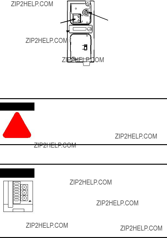
Product Drawing
ETHERNET
INTERFACE MODULE
R
CLASS I, GROUPS A,B,C, AND D, DIV 2
ETHERNET ADDRESS
EXTERNAL POWER REQUIREMENTS
24 V dc
USE EXTERNAL DC SOURCE
FOR CLASS I DIVISION 2
APPLICATIONS. SEE
INSTALLATION INSTRUCTIONS
MADE IN U.S.A.
FAULT 
LINK 
Ethernet TX/RX

POWER 
LED Indicators
The ENI has five LED indicators:
For more detailed information on LED operation, see Chapter 8, Troubleshooting.
Publication
Default Settings
The ENI???s
Table 1.1
(1) The ENI receives NAKs and ACKs, but does not generate them.
Publication

Messaging
When the ENI is connected to a programmable controller (and connected to an Ethernet network), the controller can be accessed from other devices on Ethernet, or initiate communications to other Ethernet/IP devices.
The ENI also supports SMTP mail service, that allows a controller to send
The ENI is compatible with the following devices and applications:
???All MicroLogix, SLC, and
???Personal Computers using the RSLinx (V2.30.00 and higher) DF1
???Other DF1
???RSLinx (V2.30.00 and higher) Ethernet Driver
???CompactLogix
Publication
Ethernet Networks
Basic Ethernet Topology
The ENI Ethernet connector conforms to ISO/IEC
Ethernet
Switch
to PC Ethernet Card or other Ethernet Device
RJ45 connectors on both ends of cable
to ENI
Using a Web Browser with the ENI
You can access information about the ENI via your web browser. Simply enter the ENI???s TCP/IP address into the address field of your browser.
Publication

Publication

Chapter 2
Installation and Wiring
This chapter covers installation and wiring for the ENI. It is divided into the following sections:
???European Communities (EC) Directive Compliance
???Mounting
???External Power Supply Wiring
This product has the CE mark. It is approved for installation within the European Union and EEA regions. It has been designed and tested to meet the following directives.
EMC Directive
This product is tested to meet the Council Directive 89/336/EC Electromagnetic Compatibility (EMC) by applying the following standards, in whole or in part, documented in a technical construction file:
???EN
???EN
This product is intended for use in an industrial environment.
Low Voltage Directive
This product is tested to meet Council Directive 73/23/EEC Low Voltage, by applying the safety requirements of EN
Publication
Safety Considerations
Tests. For specific information required by EN
Open style devices must be provided with environmental and safety protection by proper mounting in enclosures designed for specific application conditions. See NEMA Standards publication 250 and IEC publication 529, as applicable, for explanations of the degrees of protection provided by different types of enclosure.
This equipment is suitable for use in Class I, Division 2, Groups A, B, C, D, or
WARNING
!
Explosion Hazard
???Substitution of components may impair suitability for Class I, Division 2.
???Do not replace components or disconnect equipment unless power has been switched off and the area is known to be
???Do not connect or disconnect connectors or operate switches while circuit is live unless the area is known to be
???This product must be installed in an enclosure. All cables connected to the product must remain in the enclosure or be protected by conduit or other means.
???The ENI must be operated from an external power source.
???All wiring must comply with N.E.C. article
Use only the following communication cables and replacement connectors in Class I Division 2 Hazardous Locations.
Publication

The
ATTENTION
!
Do not remove the protective debris strip until after all the equipment in the panel is mounted and wiring is complete. Once wiring is complete, remove protective debris strip. Failure to remove strip before operating can cause overheating.
1.Mount your DIN rail.
2.Snap the DIN rail latch into the closed position.
3.Hook the top slot over the DIN rail.
4.While pressing the unit against the rail, snap the unit into position.
Publication

Removal
DIN
Side
Rail
View
1.Place a screwdriver in the DIN rail latch at the bottom of the unit.
2.Holding the unit, pry downward on the latch until the unit is released from the DIN rail.
ATTENTION
!
Be careful of metal chips when drilling mounting holes for your equipment within the enclosure or panel. Drilled fragments that fall into the equipment could cause damage. Do not drill holes above mounted equipment if the protective debris strip has been removed.
Mounting
Template
1.Remove the mounting template from the back of this document.
2.Secure the template to the mounting surface.
3.Drill holes through the template.
4.Remove the mounting template.
5.Mount the unit.
Publication
ENI Port Identification
ETHERNET
RS232
FAULT
Ethernet Port (ENI Port 1)
NET
TX/RX TX/RX
IP

Ethernet IP address
PWR
CABLE
EXTERNAL
External Power Supply
Wiring
WARNING
!
EXPLOSION HAZARD - In Class I Division 2 applications, an external, Class 2 power supply must be used. The DC Power Source selector switch on the ENI must be set to EXTERNAL before connecting the power supply to the ENI.
IMPORTANT
24
VDC
DC
NEUT
CHS
GND
Bottom View
???In
???Always connect the CHS GND (chassis ground) terminal to the nearest earth ground. This connection must be made whether or not an external 24V dc supply is used.
Publication

Ethernet Connections
Ethernet
The Ethernet connector is an RJ45,
When to use
???ENI Ethernet port to
???Direct
Publication
Ethernet Cables
Shielded and
With media converters or Ethernet switches, you can also connect to the following media:
???fiber optic
???broadband
???
???
Maintain ENI Connections
The unshielded twisted pair (UTP) patch cable on a switch should be labeled and treated as dedicated. Be careful when moving any cables, as port identity may be effected. If you are using a switch and must move the ENI to a new port for any reason,
You should also discourage any field personal from treating the ports of a switch as ???all the same???. This helps to prevent any problems with network communications being effected by moving cables.
Publication
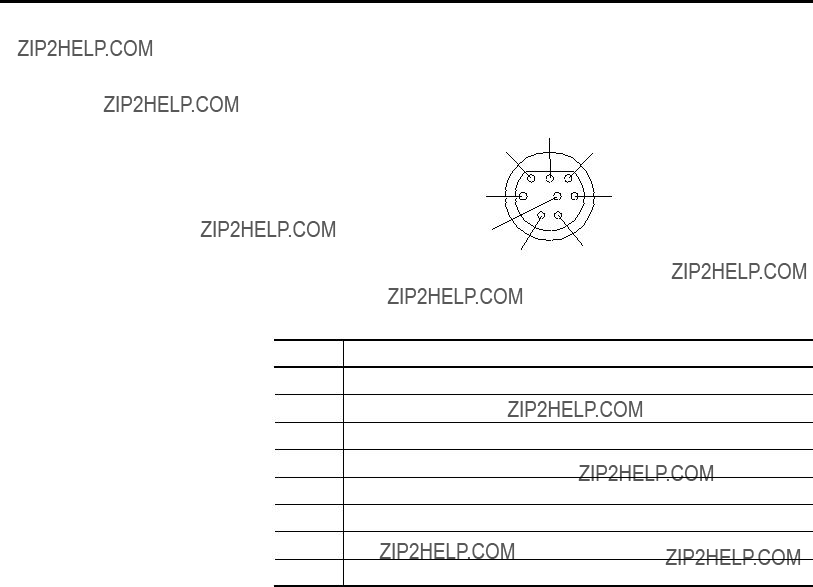
Table 2.1
124V dc
2ground (GND)
3no connection
4ENI input data, RxD
5no connection
6no connection
7ENI output data, TxD
8ground (GND)
Port 2 of the ENI is an
See page
Publication

Chapter 3
This chapter describes ENI operation. The following information is included:
???Allocation of Ethernet Connections
???Program Upload/Download and
Ethernet is the protocol used to transport TCP/IP messages. On top of TCP, Ethernet/IP is the open protocol used by the ENI. Ethernet/IP allows devices to exchange information (data); or to upload, download, and edit logic programs over Ethernet.
To communicate between devices, Ethernet/IP uses a ???connection??? model. Connections are dedicated paths across Ethernet between devices.
The ENI supports a maximum of 6 connections, allowing simultaneous communication with up to 6 other devices or applications. The connections are dedicated as follows:
Publication

Program Upload/Download
and
The ENI allows you to connect from your PC to controllers over Ethernet. The following procedure can be used when the computer has a connection directly onto Ethernet (PCI card, PCMCIA interface, built in TCP/IP port, etc.) and the ENI is plugged into the computer???s
RSLinx on Ethernet (PC Connected to Ethernet)
Follow these steps to configure RSLinx for Ethernet operation.
1. Open RSLinx and open the driver configuration dialog.
Publication

Operation
2.The ???Configure Dialog??? will open, select Ethernet devices from the available drivers, and then click ???OK??? to load the driver into RSLinx.
Once the Ethernet driver is loaded, either highlight and select ???Configure??? or simply double click on the Ethernet driver.
Publication
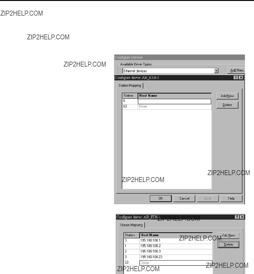
At that point the station mapping screen will appear as illustrated here. Double click on the row below ???Host Name???, and enter the TCP/IP addresses that match the devices on your network that you will need access to.
When you are done entering the stations, click OK to close the station mapping window.
Publication

Operation
3.Open the
RSLogix 500
1. Open RSLogix 500 and select ???Comms???
Publication
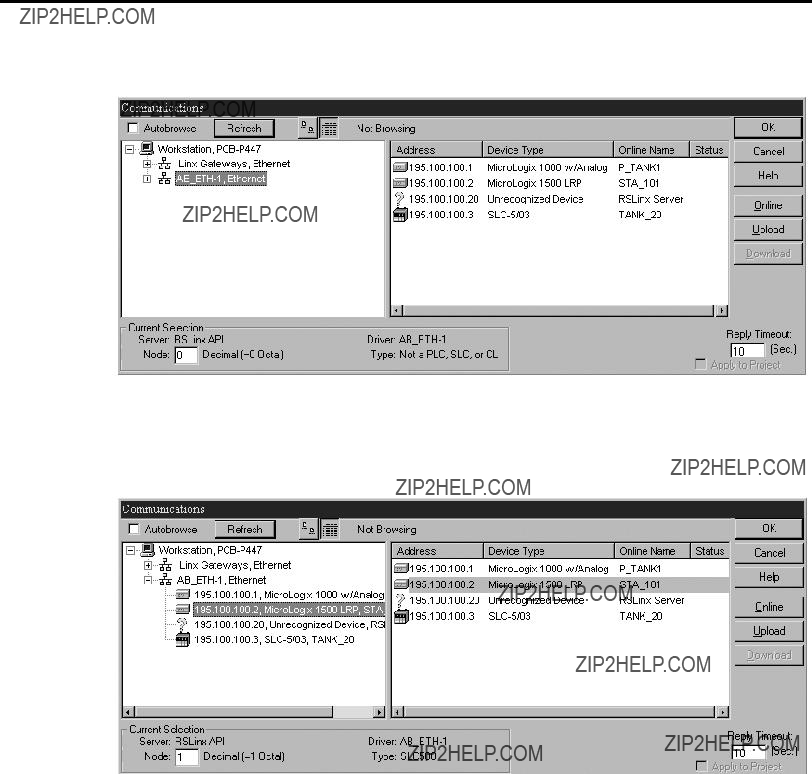
2. Select
3.Either expand the tree (select the + in the box, or select the device from the table to the right. From this point, you can then either go online or perform an upload or download.
Publication

Chapter 4
ENI Configuration (Node 248 to 254)
Configuration Methods
This chapter describes configuration methods and parameters. It is arranged as follows:
???Configuring ENI Data Parameters
???Configuring ENI String Parameters
???ENI Configuration Parameters
The ENI???s IP information can be entered using either:
???the ENI Configuration Utility
???a write message from the
???the BOOTP Utility over Ethernet (BOOTP configuration is described in Appendix B of this manual)
Publication

COM Port Settings
Use the Utility Settings screen to set the following:
???COM Port - The PC???s
???Baud Rate - Select a baud rate or choose Autobaud. See page
???Parameter Upload Behavior and Parameter Download Behavior - This setting controls which parameters will be saved or loaded when you use the Load From or Save To buttons.
Use the ENI IP Addr screen to set the following:
???232 Baud Rate - Select a baud rate or choose Autobaud. See page
???TCP/IP Parameters - See page
Publication
Save to ENI RAM or ENI ROM
You must save the configurations you have set. Click ENI RAM for temporary setups or ENI ROM to permanently save your settings. If you do not save the settings, they will revert to
Use the Email screen to fill in the information for
Publication
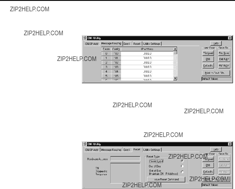
Message Routing
Use the Message Routing screen to fill in the destination addresses for DF1 messaging. Message routing is described in chapter 5.
Reset
Use the Reset screen to issue reset commands and to set the type of behavior that will occur at reset. The reset behavior options are described on page
Publication

Controller Messaging
When using this method, a write message is used to configure the TCP/IP configuration parameters. A CIF write message is initiated to the controller. CIF stands for Common Interface File and is supported by all
The first item to configure is the ENI???s IP address on your network. See the following section, Configuring ENI Data Parameters, for that configuration procedure.
The configuration parameters are described in more detail later in this chapter.
Publication

Configuring ENI Data
Parameters
This example illustrates how to configure the ENI???s TCP/IP address (Node 250).
1.Create an integer data file. Inside the file arrange your TCP/IP data in groups of 4 words (as illustrated in file N50 below).
2.Create your message logic using whatever conditional instructions you may need. In this example, bit B3:0/8 is used to condition the message instruction and message file 10, element 1 is used to manage the message session.
Publication

3.Open the message instruction and enter the appropriate variables. The variables are described in Table 4.1.
Table 4.1 Message Instruction Variables for Configuring ENI Data Parameters
4.With the controller in Run, initiate the message. The new TCP/IP information is transmitted to the ENI.
!248 information on page
Publication

Configuring ENI String
Parameters
Configuring the ENI
This example illustrates configuring the ENI
1.Create a valid string file element as illustrated below. This example has data file 25 configured for string elements. In File ST25, element 0 has a valid
Publication

2.Create your message logic using whatever conditional instructions you may need. This example uses bit B3:0/7 to condition the MSG instruction and message file 10, element 16 to manage the message session.
3.Open the message instruction and enter the appropriate variables. The variables are described in Table 4.2.
Table 4.2 Message Instruction Variables for Configuring ENI String Parameters
Publication

ENI Configuration
Parameters
The following table shows the functions that nodes 248 to 255 perform and their default values. Descriptions of each function can be found following the table.
(1)See page
(2)The ENI address, ???0.0.0.0??? will be replaced by the IP address assigned to the ENI. For example, the string may be ENI191.225.181.52@eni1761.org. If the ENI does not have an assigned IP address, the string will be read as ENI0.0.0.0@eni1761.org.
(3)Changes to the Baud Rate take effect when the ENI power is cycled, or the configuration is saved to flash.
(4)Autodetect of CRC/BCC also occurs when autobaud is selected.
These parameters are described in more detail in the following sections.
Publication
Node 248 - Save/Reset Function
Depending on the value of the Save/Reset option, the ENI performs the following operations when receiving a PCCC Unprotected Write message of one element (integer) to Node 248.
Node 249 - From String
Node 249 holds the ASCII string that is sent with any
???The From String remains at the default value unless changed by the user. See page
???The From String must contain an ???@??? symbol.
???The From String cannot contain any spaces or special ASCII characters.
???The maximum length of the From String is 64 characters. Any additional characters are ignored.
???The From String is sent from a String Table consisting of 84 characters.
???To configure the From String, initiate a message with a string element as the data. The message instruction procedure is shown on page
Publication

Node 250 - TCP/IP Configuration
This procedure describes configuration for the TCP/IP parameters. The TCP/IP parameters are configured by sending a message instruction to the ENI (or by using the ENI Configuration Utility).
1.Configure a 485CIF write message in the
2.Set the destination (target) node to 250. Using node address 250 directs this message to the TCP/IP configuration function.
3.The local integer file must be set up for at least 4 integer locations. The first 4 words define the IP address and are required. All remaining variables are optional.
The table below describes the TCP/IP functions that can be configured. The sections following the table describe the functions in more detail.
Table 4.3 TCP/IP Configuration Parameters
(1) The IP address must be configured. All other functions are optional.
Publication
ENI Configuration (Node 248 to 254)
Subnet Mask
A subnet mask is used to interpret IP addresses when the network is divided into subnets. If your network is not divided into subnets, then leave the subnet mask at the default or allow the ENI Configuration Utility to assign a default.
The subnet mask defaults to
Table 4.4 Subnet Mask
Subnet Mask
???Reading the subnet mask when the IP address is 0.0.0.0 returns a value of 0.0.0.0.
???When you manually configure the subnet mask,
???The ENI validates the configured subnet mask and if:
???The first octet is not equal to 255, the ENI returns status 0x10 and reverts to the previous mask, or
???The first octet is 255, but the remaining mask is not proper, the ENI returns status 0x10 and reverts to the previous mask.
???The definition of ???proper??? is that the mask must be a contiguous series of 1???s with no zeroes in between (i.e. 255.0.0.0 or 255.224.0.0 or 255.192.0.0 are valid, but 255.160.0.0 is not).
Security Mask
The Security Mask, when configured, allows you to restrict controller access to sources with IP addresses that are within some prescribed range. For example, if you wanted to restrict all message sources to be from within a company???s allocated IP address range, a Security Mask could be configured that would block any IP address outside that range. This only applies to messages to the controller. Web page access, for example, is not restricted.
Publication
The security masks default value is 0.0.0.0
The follow examples illustrate the behavior of the security masks:
Table 4.5 Security Mask Behavior
You can use one or two security masks. If you wish to use only one security mask, use Security Mask 1 because it takes precedence over Security Mask 2 (for example, if Security Mask 1 is accepted, Security Mask 2 is not evaluated). Details of the relationship between the two masks are shown in the following table.
Table 4.6 Using Security Mask 1 and Security Mask 2
Security masks 1 and 2 are evaluated using the following logic:
Publication

Node 251 -
The TCP/IP address stored in this location defines the mail server. The ENI sends all
Node 252 - BOOTP Configuration
The ENI allows the BOOTP request to be disabled by clearing the
BOOTP Enable parameter in the channel Configuration File. BOOTP
Enable behaves as follows:
???0 = BOOTP configuration
???1 = soft configuration
When BOOTP Enable is disabled, the ENI will wait for a manual configuration.
The BOOTP enable/disable setting is only evaluated on
See Appendix B for information on using BOOTP.
Node 253 - Baud Rate
The first time the ENI is
The ENI also performs a CRC/BCC check when autobaud is operational. It reads a test PCCC_Diagnostic Status Request to determine if CRC or BCC is being used and adjusts to it.
Publication

Table 4.7 ENI Baud Rate Options
(1) All CompactLogix devices must be configured to use two stop bits when communicating with the ENI at 38.4K.
IMPORTANT
 Hardware
Address
The ENI cannot Autobaud to 57.6K to synchronize to the attached controller. You must manually set the baud rate to 57.6K. If the controller???s baud rate is from 1200 to 38.4K, and the ENI is configured for Autobaud, the ENI will synchronize with the controller???s baud rate.
Autodetect of CRC/BCC occurs when autobaud is selected. CRC is used when a fixed baud rate is selected.
R
CLASS I, GROUPS A,B,C, AND D, DIV 2
ETHERNET ADDRESS
EXTERNAL POWER REQUIREMENTS
24 V dc
USE EXTERNAL DC SOURCE
FOR CLASS I DIVISION 2
APPLICATIONS. SEE
INSTALLATION INSTRUCTIONS
MADE IN U.S.A.
Node 254 - Ethernet Hardware Address
You will find the hardware address on a label affixed to the ENI as shown to the left. The hardware address can also be read from node address 254.
Publication

Chapter 5
Messaging Between the
ENI and DF1 Devices
This chapter describes messaging between the ENI and DF1 devices. The following topics are covered:
???Messaging Between the ENI and DF1 Devices
???Message to Configuration Nodes (Nodes 100 to 149)
???Sending a Message to a Destination Controller (Nodes 0 to 49)
The ENI can route a DF1 message received from the attached controller to a compatible destination TCP/IP device.
This is accomplished by using DF1 node addresses 0 through 49. ENI Node addresses 100 through 149 store TCP/IP destination addresses. When the ENI receives a write message to nodes 100 to 149, it stores the TCP/IP destination address in the corresponding map register.
To configure the destination TCP/IP addresses, you can use either the ENI Configuration Utility, or you can send a 485CIF message to each node as described in this section.
Publication

The table below illustrates the relationship between messages and their corresponding configuration addresses.
Table 5.1 Message Routing
If the received data matches the current configuration, the ENI closes any open communications with the destination device.
If the ENI receives a PCCC read message to any of its configuration addresses (nodes 100 to 149), the ENI responds with the current configuration of that node/address.
Using the configuration shown in Table
Publication

Message to Configuration Nodes (Nodes 100 to 149)
When the ENI receives a message to Node Address 0 to 49, it looks up the TCP/IP address associated with the address at Nodes 100 to 149. The ENI preserves the original DF1 address when sending back a reply.
The following table illustrates the relationship between configuration addresses and their corresponding messaging address.
Table 5.2
(1) See IMPORTANT note below about assigning Nodes to various devices.
Node addresses 0 through 44 are to be used for all other Ethernet devices, such as other
To configure the route address (nodes 100 to 149), write a 485CIF message with 4 integer data words. An example is shown in the next section of this chapter.
Publication
Sending a Message to a Destination Controller (Nodes 0 to 49)
The ENI uses a pair of node addresses to send data messages over TCP/IP. For data, two sets of addresses are used as illustrated in the table below. Node numbers 100 to 149 are used to define or store the actual TCP/IP address, and nodes 0 to 49 are used to send the data to the destination.
Table 5.3 DF1 Message Routing
(1) See IMPORTANT note below about assigning Nodes to various devices.
Node addresses 0 through 44 are to be used for all other Ethernet devices, such as other
The procedure to send configuration data (nodes 100 to 149), or data (nodes 0 to 49) is exactly the same as discussed previously in ???Configuring ENI Data Parameters??? on page
Publication

Open the message instruction and enter the appropriate variables. The variables are described in Table 5.4.
Table 5.4 Message Instruction Variables for Sending a Message to a Destination
Controller
Publication

Publication
Chapter 6
Overview
This chapter describes using the ENI???s
???Overview
The ENI is capable of transmitting
To send an
Publication
Configuring
SMTP
To configure the
???SMTP mail server IP address - configured by sending a write message to node 251
???A ???From??? String - configure by sending a write message to node 249 (from string). The string element text can be stored in a String File as shown below. The string element text (ASCII characters) contains the verbatim ???from??? string. See page
Publication

Destination Addresses
The ENI stores
Message Text
To send the actual
The following table shows the relationship between the
Publication

Message Fields (to, from, subject)
The ENI includes the ???to???, ???from???, and ???subject??? fields in the body of the message.
The default ???from??? text is ENI0.0.0.0@eni1761.org. This can be changed in the ENI configuration, Node 249. See page
The standard format of the ???subject??? line is:
Subject: 1761ENI.MSG(plus the first 32 characters of text)
For example, if the message text was ???The quick brown fox jumped over the lazy dog???s back???, the ???subject??? line would read:
Subject 1761ENI.MSG(The quick brown fox jumped over )
Publication

Sending an
Message
The ENI uses a pair of node addresses to send
1. Start by configuring a MSG instruction.
Publication

2.Open the message instruction and enter the appropriate variables. The variables are described in Table 6.1.
Table 6.1 Message Instruction Variables for Sending an
Publication
Chapter 7
Connecting
The chapter contains an example of using the ENI on an Ethernet network. It is arranged as follows:
???Purpose
???Scope
???General Ethernet Information
???Configuring
???Configuring
???Configure RSLINX and Download The Program To The
???Create MSG Programs for the SLC 5/05 and the 5550 Controllers
System Diagram
Figure 7.1 Example Network
ENI Network
Personal Computer with RSLogix 5000, RSLogix 500 and RSLinx
Publication

Purpose
Scope
The computer must include the following software:
???RSLOGIX5000, version 7.00 or later
???RSLINX, version 2.30.00 or later
???RSLOGIX500
???ENI Configuration Tool
The
The Ethernet Interface Card in the computer is used to connect directly to the SLC 5/05 controller (channel 1) and to the 5550 controller via the
Provide Ethernet connectivity for
Connecting
The ENI must be configured with IP addresses assigned to node numbers 0 to 49. The Destination Node Address in DF1 messages is then used by the ENI to route the message to the proper device on Ethernet.
This application example will show how to configure the ENI module and how to send messages from the
Publication

General Ethernet
Information
Each Ethernet device requires a unique IP address. If your Ethernet network is isolated from the
Table 7.1 Example Network IP Addresses
The subnet mask for each Ethernet device is then, 255.255.0.0.
When using 38400 baud, the number of Stop Bits in
RSLINX and in the L20 controller must be set to 2.
Rungs 0 and 1, shown in Figure 7.2, of the
This is recommended for the
Publication

Figure 7.2 Throttling Message Instructions
Configuring
Refer to Chapter 4 of this manual for information on how to obtain the free ENI Configuration Software Tool.
The first task is to configure the ENI module that will be connected to the computer. This is ENI #1 per Figure 7.1. A
Figure 7.3 ENI Configuration Tool ENI IP Addr Screen
Publication
For this example, we will be using 38400 baud on all serial connections. We will also assign IP addresses to all Ethernet products rather than using BOOTP.
Two tabs in the ENI software tool must be modified for the purposes of this example, the ???ENI IP Addr??? tab and the ???Message Routing??? tab. The IP address for the ENI connected to the
Figure 7.4 ENI #1 Configuration - ENI IP Addr Screen
Figure 7.5 ENI #1 Configuration - Message Routing Screen
Before we download our configuration to ENI #1, we must configure the ???Utility Settings??? tab in the ENI configuration tool. Make this tab look like the following.
Figure 7.6 ENI #1 Configuration - Utility Settings Screen
Publication

Configuring
Then, connect the serial cable between your computer and ENI #1 and click on the ENI IP Addr tab. From this tab, under the ???Save To??? column, click the ENI ROM button. This will download your configuration parameters to ENI #1 and save it to
ENI #2 is connected to the L20 controller. This ENI must be configured with its own IP address (131.200.50.94 for this example) and we must add the IP addresses of the SLC 5/05 controller and the
Table 7.2 Message Routing
At this point we could merely configure ENI #2 as we did ENI #1. Or, we could use the method outlined in Chapter 5 to configure ENI #2. This method sends configuration Messages from the L20 controller via the DF1 link. If for any reason this ENI would need to be replaced, it could then be easily and quickly configured via messages from the L20 controller. A ladder program to accomplish this is as follows:
Publication

Figure 7.7 ENI #2 Configuration - RSLogix 5000 Ladder Program
The above ladder rungs, 2 through 7 and the rungs, 0 and 1 shown earlier in this application example, make up the ladder program for the L20 controller. Details of each MSG Instruction will follow.
In the above program, Rung 2 initiates the string of configuration messages with input instruction ???Reconfig_ENI???. This could be an alias to an input connected to a pushbutton for example, for quick configuration of the ENI module.
Publication

The 5 rungs used to configure ENI #2 are defined as follows:
Table 7.3 ENI #2 Configuration - Rung Descriptions
Rung Function
Rung 2 This rung initiates the process and configures the ENI module???s Serial port for 38400 Baud.
Rung 3 This rung is initiated by the Done bit of the previous MSG and it disables
BOOTP.
Rung 4 This rung configures the ENI with its own IP address.
Rung 5 This rung adds the IP address of the SLC 5/05 controller to the ENI module???s Message Routing table at DF1 node 1. This means that any message sent by the
Rung 6 This rung adds the IP address of the
Rung 7 This rung instructs the ENI module to save the configuration data sent to it in
The following table contains the information needed to send messages to the ENI to configure it for this example. For a complete list of ENI configurable features, please refer to Chapters 4 and 5.
Table 7.4 ENI #2 Configuration - Message Instructions Parameters
Publication

For this example, as mentioned earlier, we will assign the following IP addresses to the devices on Ethernet:
Table 7.5 Example IP Addresses for Ethernet Devices
The Message Instructions for the L20 controller, Rungs 2 through 7, used to configure the ENI module, must be ???PLC2 Unprotected Write??? Message Type. The ???Destination Element??? can be any valid PLC2 command value. ???010??? is used in this example because it is the first available valid value. This parameter is not used by the ENI, but must be a valid value for RSLOGIX5000 to accept it.
An example of the MSG Configuration tab and the Communication tab for the MSG Instruction used to configure the IP address for the ENI (Rung 4) are as follows:
Publication
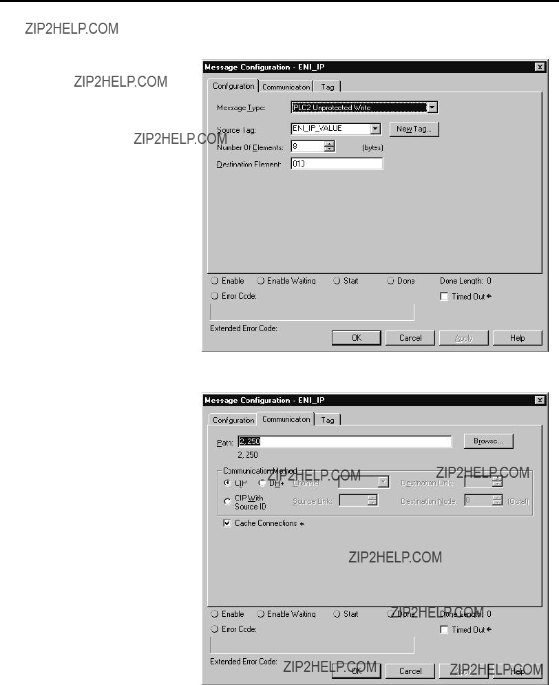
Figure 7.8 ENI #2 Configuration - Message ConfigurationTab
Figure 7.9 ENI #2 Configuration - Message CommunicationTab
Note that the MSG length is 8 bytes or 4 integer words. These 4 words contain the IP address for ENI #2 and are stored in tag ENI_IP_VALUE, which is a tag address containing 4 integer words. This is shown in
Publication

the L20 controller???s tag database shown below. On the MSG Instruction???s Communication tab above, the path is ???2,250???, where the 2 represents the L20 controllers serial port and the 250 tells the ENI module that the 4 words of data contain its IP address.
Figure 7.10 L20 Controller???s Tags
Per Table 7.4, The MSGs in Rungs 2, 3 and 7 are 2 bytes or 1 integer word in length. Their Paths are ???2,253???, ???2,252??? and ???2,248??? respectively; where 253 represents Baud Rate, 252 represents BOOTP Enable/Disable, and 248 represents the Save function.
The single integer data value for these messages is shown in Table 7.4. ???0??? is the value for the Save MSG data tag (ENI_SAVE_TO_FLASH_VALUE), which instructs the ENI to save its configuration to
Per Table 7.4, The MSGs in Rungs 5 and 6 assign IP addresses to node numbers in the ENI module???s Message Routing Table. These two MSG Instructions are the same as the MSG Instruction in Rung 3, except the paths are 2,101 and 2,145 and the data tags have different names; this time containing the IP addresses of the SLC 5/05 and
Publication

Enter your
If you do not change this parameter in your
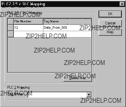
Finally, since Logix controllers do not use the structured data table addressing scheme used by PLC and SLC controllers, we must map file numbers used in the commands sent to any Logix controller to tag names within them. For example, a MSG sent by an SLC 5/05 controller to the L20 controller uses a
While offline in the L20 controller project, click on the Logic
Figure 7.11 File Mapping in RSLogix 5000
Publication
Configure RSLINX and
Download The Program To
The
In the File Number column enter 12. Under the Tag Name, click on the right side in the white box to reveal your Controller Tags and select the tag name you created for this purpose (???Data_From_505??? for this example). More than one entry may be mapped. When finished, your Map PLC/SLC screen for the L20 controller should look like the following:
Figure 7.12 File Mapping for the L20 Controller in RSLogix 5000
Save your program.
The ladder program written for the L20 controller is downloaded to the controller via the two ENI modules. A
Start RSLINX. From the ???Communication??? pull down menu, select ???Configure Drivers???. From the Configure Driver screen, click on the arrow next to the ???Available Drivers Box??? to reveal all RSLINX drivers. Click on ???RS232 DF1 devices???, then click on ???Add New???. Click OK to the
Publication
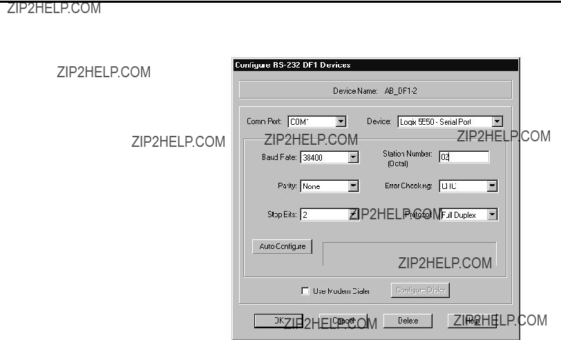
Figure 7.13 Modify DF1 Parameters Using RSLInx
It is very important that the ???Station Number??? match the ???Destn??? number in ENI #1, assigned to the IP address for ENI #2. In this example, we arbitrarily used Destn address 2 to represent IP address 131.200.50.94, which is the IP address of ENI #2.
DO NOT click on the ???Auto Configure??? button on this screen.
When you have properly modified the parameters on this screen, click OK. Then close the Configure Drivers screen.
Open the WHO Active screen by clicking on the Communications
Start RSLOGIX5000. Open the
Publication
Create MSG Programs for the SLC 5/05 and the 5550 Controllers
We must now create MSG ladder programs for our other two controllers on Ethernet. The following is the MSG ladder program for the SLC 5/05 controller, developed with RSLOGIX500. Following the ladder program are four additional screens showing the two tabs for each MSG Instruction. Before saving your program, be sure to configure Channel 1 with its IP address, subnet mask and disable BOOTP. Then, save your program.
Figure 7.14 SLC 5/05 Controller Ladder Program
Publication

Figure 7.15 SLC 5/05 Rung 0 MSG ???General??? Tab
Figure 7.16 SLC 5/05 Rung 0 MSG ???Multihop??? Tab
Publication
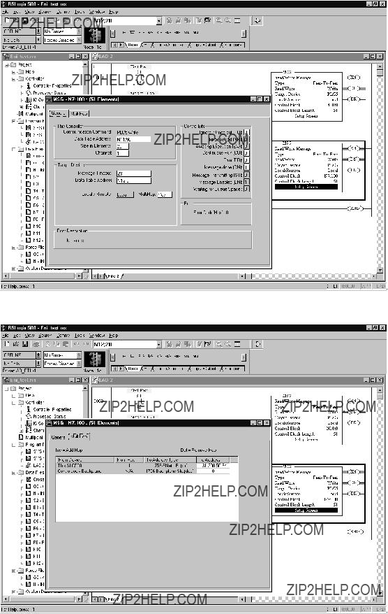
Figure 7.17 SLC 5/05 Rung 1 MSG ???General??? Tab
Figure 7.18 SLC 5/05 Rung 1 MSG ???Multihop??? Tab
Publication

The following is the MSG ladder program for the 5550 controller, developed with RSLOGIX5000. Following the ladder program are four additional screens showing the two tabs for each MSG Instruction. As part of your program, you must configure your
Figure 7.19 ControlLogix 5550 Controller Ladder Program
Publication

Figure 7.20 ControlLogix 5550 Rung 0 Message Configuration Tab
Figure 7.21 ControlLogix 5550 Rung 0 Message Communication Tab
Publication
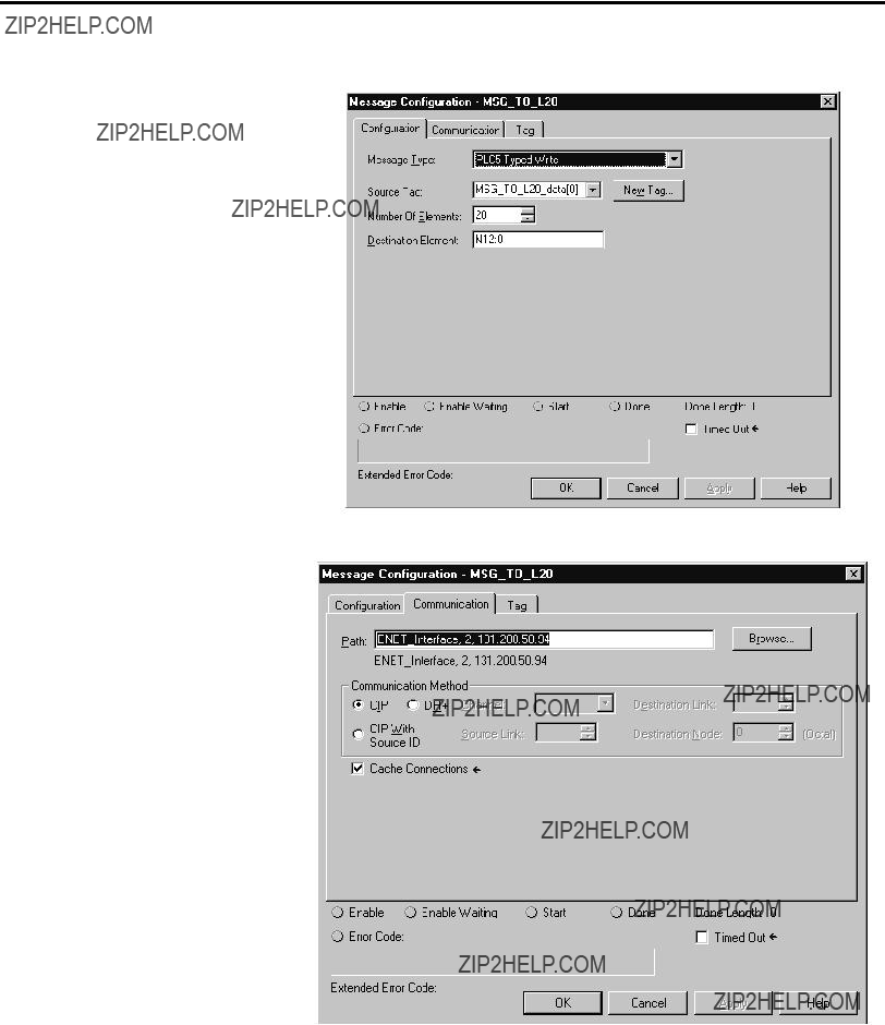
Figure 7.22 ControlLogix 5550 Rung 1 Message Configuration Tab
Figure 7.23 ControlLogix 5550 Rung 1 Message Communication Tab
The
Publication

Configuring an Ethernet
Driver in RSLINX
addresses do not exist in Logix controllers, so they must be mapped to existing tags in these controllers.
From the Logic pull down menu, select ???Map PLC/SLC Messages???. Your mapped table for your 5550 program should look like the following:
Figure 7.24 File Mapping for the ControlLogix 5550 Controller in RSLogix 5000
Save your program.
In order to download your programs to the SLC 5/05 controller and to the 5550 controller via Ethernet, we must configure an Ethernet driver in RSLINX.
In RSLINX, click on the Communications
Modify this screen to include the IP addresses of the SLC 5/05 and the
Publication

Figure 7.25 Configure Ethernet Driver Using RSLinx
From the RSLOGIX500 programming software, you should now be able to download your SLC 5/05 program. Then, from the RSLOGIX5000 software you should now be able to download your 5550 controller program.
Once all programs are downloaded to their respective controllers, place each controller into the RUN mode and a MSG from each controller will be sent to each of the other controllers. Each controller will only send one MSG at any given time. Go online with the SLC 5/05 and 5550 controllers to verify the successful completion of their Messages.
Publication

Chapter 8
Troubleshooting
This chapter covers the following Troubleshooting topics:
???Troubleshooting Using the LED Indicators
???Error Codes Generated by the ENI
???Message Instruction Error Codes
LED Sequence at
Publication

The ENI status LEDs provide a mechanism to determine the current status of the ENI if a programming device is not present or available. The LED behavior is described in the following table.
Publication
Troubleshooting
Error Codes Generated by the ENI
This table shows the error codes that may be generated by the ENI. A full listing of error codes that may be generated by the Message Instruction is shown below.
Message Instruction Error
Codes
When the controller detects an error during the transfer of message data, the controller sets the ER bit and enters an error code that you can monitor from your programming software.
Publication

Publication

Troubleshooting
Publication

Publication

Appendix A
Specifications
Physical Specifications
Ethernet Specifications
MicroLogix Web Site
Communication Rate: 10 Mbps
Connector:
Visit http://www.ab.com/micrologix for more information on MicroLogix products. You can find a variety of application information and White Papers covering specific technical topics.
Publication

Dimensions
Mounting Dimensions
52.07 mm
(2.05 in)
118 mm
(4.64 in)
27.7 mm
(1.09 in)
Product Dimensions
52.07 mm
(2.05 in.)
Allow 15 mm (0.6 in.) clearance for DIN rail latch movement during installation and removal.
107 mm
(4.20 in)
Allow 15 mm (0.6 in.) clearance for DIN rail latch movement during installation and removal.
Publication
Appendix B
BOOTP Configuration Method (default)
BOOTP (Bootstrap protocol) is a
To use BOOTP, a BOOTP Server must exist on the local Ethernet Subnet. The server is a computer that has BOOTP Server software installed and running which reads a text file containing network information for individual nodes on the network.
When the ENI receives a configuration message via BOOTP, it uses the data within the message to configure its TCP/IP parameters.
Table 2.1 TCP/IP Parameters
(1)Depending upon whether your BOOTP server allows these optional fields to be included, you might not be able to configure these parameters using the BOOTPTAB file. If that is the case, configure them using the soft configuration method. See page
Publication
Using BOOTP
When BOOTP is enabled, the following events occur at
???The ENI broadcasts a
???The BOOTP server compares the hardware address with the addresses in its
???The BOOTP server sends a message back to the ENI with the IP address and other network information that corresponds to the hardware address it received.
With all hardware and IP addresses in one location, you can easily change IP addresses in the BOOTP configuration file if your network needs change.
The ENI allows the BOOTP request to be disabled by clearing the BOOTP Enable parameter. See Node 252 - BOOTP Configuration on page
The optional BOOTP Server file contains
???install the
???edit the
???run the
Install the BOOTP Server
To install the DOS BOOTP server:
1.Unzip the software to a known directory.
2.Change to that directory.
3.Type install, and press [Enter].
4.The software is installed in C:\ABIC\BIN. If you are using DOS, put this directory in the path statement of your AUTOEXEC.BAT file.
Publication

Edit the BOOTP Configuration File
The
C:\ABIC\BIN directory. BOOTPTAB is an ASCII file that looks like:
#Legend:gw
#vm
#Default string for each type of Ethernet client defaults5E: ht=1:vm=rfc1048
#Entries for SLC 5/05 processors:
sigma1: tc=defaults5E:ip=12.34.56.1:ha=0000BC1D1234
sigma2: tc=defaults5E:ip=12.34.56.2:ha=0000BC1D5678
sigma3: tc=defaults5E:ip=12.34.56.3:ha=0000BC1D9012
This file contains the information needed to boot the ENI.
You must edit the BOOTPTAB file to include the name, IP address, and hardware address for each ENI you want the server to boot. To edit this file:
1.Open the BOOTPTAB file using a text editor such as Notepad or Wordpad.
The file contains text that look like this:
#Default string for each type of Ethernet client
defaults5E: ht=1:vm=rfc1048
These are the default parameters for the ENI and must always precede the client lines in the BOOTPTAB file.
The file also contains a line that looks like this:
#Entries for SLC 5/05 processors: sigma1:tc=defaults5E:ip=12.34.56.1:ha=0000BC1D 1234
The ???#??? character defines the line as information, not configuration data.
(1)1 = 10 MB Ethernet
(2)Use rfc 1048.
Publication

HP 9000
HP UNIX Computer
2.Make one copy of the configuration template for each ENI in your system.
3.Edit each copy of the template as follows:
a.Replace ???sigma1??? with the name of the ENI. Use only letters and numbers; do not use underscores.
b.Replace ???12.34.56.1??? with the IP address to be assigned to the ENI.
c.Replace ???ha=0000BC1D1234??? with the ENI???s hardware address. Use only hexadecimal digits
4.Save, close, and make a backup copy of this file.
Example BOOTPTAB File
In this example there are three SLC 5/05 processors and an HP 9000 programming terminal. The names and hardware addresses are device specific:
802.3 Ethernet (TCP/IP)
BOOTP Server
Publication
BOOTP Configuration Method (default)
Based on this configuration, the BOOTPTAB file looks like:
#Legend:gw
#vm
#Default string for each type of Ethernet client defaults5E: ht=1:vm=rfc1048
#Entries for SLC 5/05 processors:
sigma1: tc=defaults5E:ip=12.34.56.1:ha=0000BC1D1234
sigma2: tc=defaults5E:ip=12.34.56.2:ha=0000BC1D5678
sigma3: tc=defaults5E:ip=12.34.56.3:ha=0000BC1D9012
Run the Boot Server Utility You can run either the
If you have BOOTP enabled and the message BOOTP response not received appears, check the cabling connections and the BOOTP server system.
Both utilities are located in the C:\ABIC\BIN directory and use the information contained in the BOOTPTAB file.
Be sure to place the BOOTPTAB file in the directory from which you are running the BOOTP utility. If this file is not found in that directory, the utility will try to find the file in the directory specified by the environment variable ABIC_CONFIG.
(1)1 = 10 MB Ethernet
(2)Use rfc 1048.
Publication

Running the
To run the
1.At the DOS prompt, type:
DTLBOOTD
Once you invoke the utility, it runs until the specified exit parameter is satisfied. Exit any time by pressing [Esc].
2.Apply power to all ENIs. At
address and other configuration data to the client via a BOOTP reply.
Running the
To run the
1.Start Microsoft Windows??, if it is not already running.
2.Start the utility. It will run until you terminate it by closing the DTLBOOTW.EXE window and exiting from Windows.
3.Apply power to all ENIs. At
Publication

Glossary
ASA (Advanced System Architecture)
Autobaud
A feature that allows a communications port to automatically synchronize to the device or network that it is attached to. This feature typically minimizes the amount of configuration required, and also makes is easier to replace devices.
Auto BCC/CRC
Sends a test message during autobaud to detect which Error Detecting setting to use, BCC or CRC. This will not occur for fixed baud rate settings. The ENI uses CRC for fixed baud rates.
Baud Rate
The speed of communication between devices on a network. All devices must communicate at the same baud rate. For example, the
CIP (Control and Information Protocol)
DNI (DeviceNet Network Interface)
DF1
DF1 is a standard (open)
DF1 Protocol
A
ENI (Ethernet Network Interface)
Ethernet Network
A local area network with a baseband communication rate of 10M bits per second.
Publication

Glossary 2
A
IP (Internet Protocol)
IP specifies the format of packets and the addressing scheme. Most networks combine IP with a
IP by itself is something like the postal system. It allows you to address a package and drop it in the system, but there's no direct link between you and the recipient. TCP/IP, on the other hand, establishes a connection between two hosts so that they can send messages back and forth for a period of time.
IP Address
A
NetLinx Services
The NetLinx services occur over the
Network
A series of stations (nodes) connected by some type of communication medium. A network may be made up of a single link or multiple links.
Node
Also called a station. An address or software location on the network.
MTA (Mail Transfer Agent)
The software function responsible for delivering outgoing mail to its final destination.
Publication

Glossary 3
PCCC (Programmable Controller Communications Commands)
An EIA standard that specifies electrical, mechanical, and functional characteristics for serial binary communication circuits.
Security Mask
The Security Mask, when configured, allows you to restrict incoming TCP/IP and/or UDP messages to have source IP addresses that are within some prescribed range. For example, if you wanted to restrict all message sources to be from within a company???s allocated IP address range, a Security Mask could be configured that would block any IP address outside that range.
SMTP (Simple Mail Transfer Protocol)
This protocol defines the interface and commands with the Mail Transfer Agent and defines how the ENI will deliver the outgoing mail.
Term that refers to how many ???different??? networks a message must traverse to reach its destination. For the ENI, a
TCP (Transmission Control Protocol)
TCP is one of the main protocols in TCP/IP networks. Whereas the IP protocol deals only with packets, TCP enables two hosts to establish a connection and exchange streams of data. TCP guarantees delivery of data and also guarantees that packets will be delivered in the same order in which they were sent.
TCP/IP (Transmission Control Protocol/Internet Protocol)
The suite of communications protocols used to connect hosts on the Internet. TCP/IP uses several protocols, the two main ones being TCP and IP. TCP/IP is built into the UNIX operating system and is used by the Internet, making it the de facto standard for transmitting data over networks. Even network operating systems that have their own protocols, such as Netware, also support TCP/IP.
UCMM (Unconnected Message Manager)
The UCMM is an object defined in the CIP protocol. This object is responsible for handling connection requests and unconnected message traffic.
Publication

Glossary 4
UTP (Unshielded Twisted Pair)
The type of cable used in 10BaseT systems.
Publication

Index
A
contacting for assistance
ASA
definition
Auto BCC/CRC
definition
Autobaud
definition
B
Baud Rate
configuring
BOOTP
edit configuration file
IP address
C
CE Mark
CIP
definition
Common Techniques Used in this Manual
Configuration
BOOTP
controller messaging
list of parameters
via message instruction
Configuration Utility
Configuring
BOOTP host
Connections
allocation of Ethernet connections
Contacting
D
DF1
DF1 Protocol
default settings
Dimensions
DNI
definition
DOS Host
for BOOTP
E
EMC Directive
ENI
configuration
port identification
ENI Configuration Utility
Error Codes
Ethernet Connections
Ethernet Hardware Address
Ethernet Network
connections
ENI connection
Ethernet Port
Example
BOOTP
using the CompactLogix serial port to connect to an Ethernet network
Explosion Hazard
Publication

2 Index
F
Fault LED
definition
G
Grounding
H
Hardware Features
Hazardous Location
I
Installation and Wiring
Integer Files
IP
definition
IP Address
ENI
L
LED Indicators
LED Sequence at
LInk LED
Low Voltage Directive
M
Manuals, Related
Memory Map
Mounting
dimensions
MTA
definition
N
Netlinx Services
definition
Network
definition
Node
definition
O
Operating Modes
Operation
P
PCCC
definition
Peer Connections
Power Supply Wiring
R
Related Publications
cables
ENI port
pin assignments
RSLinx
Publication

Index 3
Publication

4 Index
Publication

Publication
?? 2001 Rockwell International Corporation. Printed in the U.S.A.