Revision history
iii
HP Mini 1101, HP Mini 110, HP Mini 110 by Studio Tord Boontje, and Compaq Mini 110
Maintenance and Service Guide
?? Copyright 2009
Development Company, L.P.
Bluetooth is a trademark owned by its proprietor and used by
The information contained herein is subject to change without notice. The only warranties for HP products and services are set forth in the express warranty statements accompanying such products and services. Nothing herein should be construed as constituting an additional warranty. HP shall not be liable for technical or editorial errors or omissions contained herein.
Second Edition: October 2009
First Edition: May 2009
Document Part Number:
Revision A
Revision history
iii
iv Revision history

Safety warning notice
WARNING! To reduce the possibility of
v
vi Safety warning notice

Table of contents
vii
viii
ix
x
1 Product description
1

2 Chapter 1 Product description

3

4 Chapter 1 Product description

2 External component identification
Components included with the device may vary by region and model. The illustrations in this chapter identify the standard features on most device models.
Top components
TouchPad

Light
6 Chapter 2 External component identification
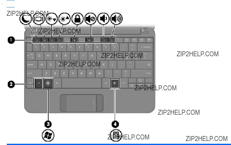
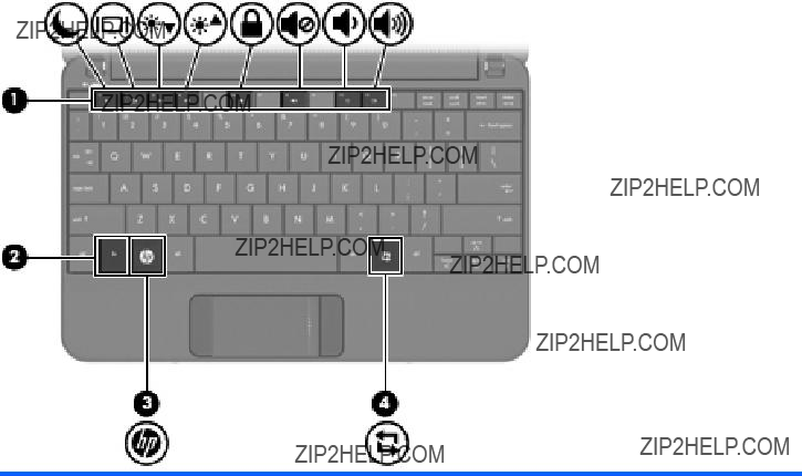
Keys
 NOTE: Refer to the illustration that most closely matches your computer.
8 Chapter 2 External component identification

Front components
batteries in the device are fully charged. If the device is not plugged into an external power source, the light stays off until the battery reaches a low battery level.

NOTE: A wireless network must be set up in order to establish a wireless connection.
10 Chapter 2 External component identification
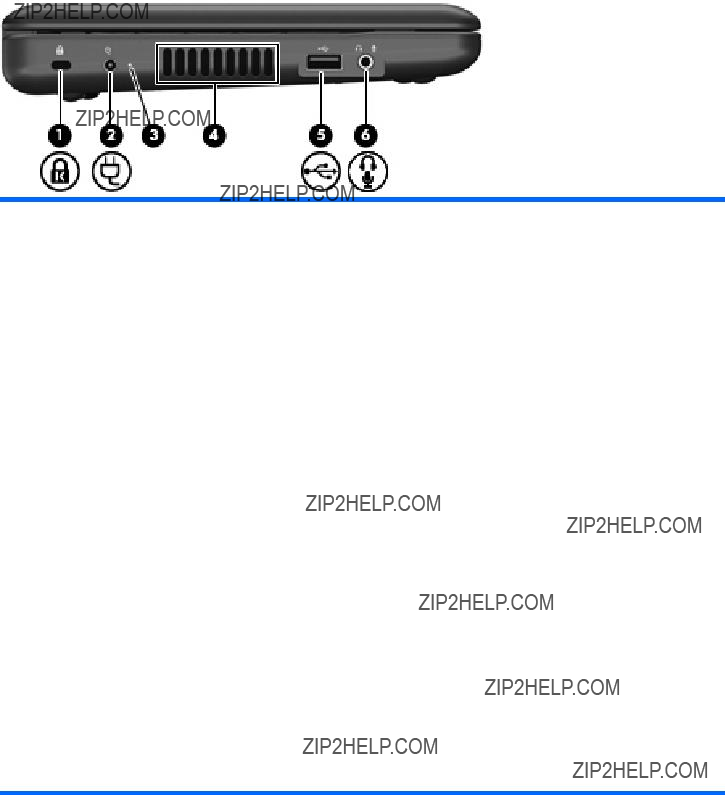
WARNING! To reduce the risk of personal injury, adjust the volume before putting on headphones, earbuds, or a headset. For additional safety information, refer to the Regulatory, Safety and Environmental Notices.
NOTE: When an audio component is connected to the jack, the device speakers are disabled.
The audio component cable must have a
12 Chapter 2 External component identification

Display components
Display components 13

Bottom components
14 Chapter 2 External component identification

Wireless antennas
*The antennas are not visible from the outside of the device. For optimal transmission, keep the areas immediately around the antennas free from obstructions.
To see wireless regulatory notices, refer to the section of the Regulatory, Safety and Environmental Notices that applies to your country or region.
Wireless antennas 15
3 Illustrated parts catalog
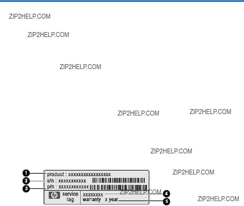
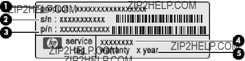
Service tag
When ordering parts or requesting information, provide the computer serial number and model description provided on the service tag:
(1)Product name: This is the product name affixed to the front of the device.
(2)Serial number (s/n): This is an alphanumeric identifier that is unique to each product.
(3)Part number/Product number (p/n): This number provides specific information about the product's hardware components. The part number helps a service technician to determine what components and parts are needed.
(4)Model description: This is the alphanumeric identifier used to locate documents, drivers, and support for the device.
(5)Warranty period: This number describes the duration of the warranty period for the device.
16 Chapter 3 Illustrated parts catalog

Device major components
(1)Display assembly (includes 1 webcam, 1 microphone, 1 speaker box, and 2 WLAN antenna transceivers/cables; WWAN on select models only)
See Display assembly components on page 25 for a comprehensive list of display assembly spare parts.
For use with black HP models only
Device major components 17

(2)Keyboard
For use only on black and blue models with Windows operating system installed
18 Chapter 3 Illustrated parts catalog

Device major components 19

20 Chapter 3 Illustrated parts catalog
Device major components 21

22 Chapter 3 Illustrated parts catalog

Argentina, Armenia, Aruba, Australia, Austria, Azerbaijan, the Bahamas, Bahrain, Bangladesh, Barbados, Belarus, Belgium, Belize, Benin, Bermuda, Bhutan, Bolivia, Bosnia and Herzegovina, Botswana, Brazil, the British Virgin Islands, Brunei, Bulgaria, Burkina Faso, Burundi, Cameroon, Cape Verde, the Central African Republic, Chad, Chile, Colombia, Comoros, the Congo, Costa Rica, Croatia, Cyprus, the Czech Republic, Denmark, Djibouti, Dominica, the Dominican Republic, East Timor, Ecuador, Egypt,
El Salvador, Equatorial Guinea, Eritrea, Estonia, Ethiopia, Fiji, Finland, France, French Guiana, Gabon, Gambia, Georgia, Germany, Ghana, Gibraltar, Greece, Grenada, Guadeloupe, Guatemala, Guinea,
the Republic of Moldova, Romania, Russia, Rwanda, Samoa, San Marino,
Sao Tome and Principe, Saudi Arabia, Senegal, Serbia, the Seychelles, Sierra Leone, Singapore, Slovakia, Slovenia, the Solomon Islands, Somalia, South Africa, South Korea, Spain, Sri Lanka, St. Kitts and Nevis, St. Lucia, St. Vincent and the Grenadines, Suriname, Swaziland, Sweden, Switzerland, Taiwan, Tajikistan, Tanzania, Togo, Tonga, Trinidad and Tobago, Tunisia, Turkey, Turkmenistan, Tuvalu, Uganda, Ukraine,
the United Arab Emirates, the United Kingdom, Uruguay, Uzbekistan, Vanuatu, Venezuela, Vietnam, Yemen, Zaire, Zambia, and Zimbabwe
(11)WWAN module
NOTE: Not available for computers with Mobile Mi installed.
For use on the following model numbers only: HP:
Device major components 23

24 Chapter 3 Illustrated parts catalog

Display assembly components
Display assembly components 25

26 Chapter 3 Illustrated parts catalog

Mass storage devices
 NOTE: Each hard drive spare part kit and
(1)Hard drive (select models only)
Mass storage devices 27

Miscellaneous parts
28 Chapter 3 Illustrated parts catalog

Sequential part number listing
Brazil, the British Virgin Islands, Brunei, Bulgaria, Burkina Faso, Burundi, Cameroon, Cape Verde, the Central African Republic, Chad, Chile, Colombia, Comoros, the Congo, Costa Rica, Croatia, Cyprus, the Czech Republic, Denmark, Djibouti, Dominica, the Dominican Republic, East Timor, Ecuador, Egypt, El Salvador, Equatorial Guinea, Eritrea, Estonia, Ethiopia, Fiji, Finland, France, French Guiana, Gabon, Gambia, Georgia, Germany, Ghana, Gibraltar, Greece, Grenada, Guadeloupe, Guatemala, Guinea,
Sequential part number listing 29

30 Chapter 3 Illustrated parts catalog
Sequential part number listing 31

32 Chapter 3 Illustrated parts catalog

Sequential part number listing 33

34 Chapter 3 Illustrated parts catalog

Sequential part number listing 35

36 Chapter 3 Illustrated parts catalog

4 Removal and replacement procedures
Preliminary replacement requirements
Tools required
You will need the following tools to complete the removal and replacement procedures:
???
???Magnetic screwdriver
???Phillips P0 and P1 screwdrivers
Service considerations
The following sections include some of the considerations that you must keep in mind during disassembly and assembly procedures.
 NOTE: As you remove each subassembly from the device, place the subassembly (and all accompanying screws) away from the work area to prevent damage.
Plastic parts
 CAUTION: Using excessive force during disassembly and reassembly can damage plastic parts. Use care when handling the plastic parts. Apply pressure only at the points designated in the maintenance instructions.
Cables and connectors
 CAUTION: When servicing the device, be sure that cables are placed in their proper locations during the reassembly process. Improper cable placement can damage the device.
Cables must be handled with extreme care to avoid damage. Apply only the tension required to unseat or seat the cables during removal and insertion. Handle cables by the connector whenever possible. In all cases, avoid bending, twisting, or tearing cables. Be sure that cables are routed in such a way that they cannot be caught or snagged by parts being removed or replaced. Handle flex cables with extreme care; these cables tear easily.
Preliminary replacement requirements 37

Drive handling
CAUTION: Drives are fragile components that must be handled with care. To prevent damage to the device, damage to a drive, or loss of information, observe these precautions:
Before removing or inserting a hard drive, shut down the device. If you are unsure whether the device is off or in Hibernation, turn the device on, and then shut it down through the operating system.
Before handling a drive, be sure that you are discharged of static electricity. While handling a drive, avoid touching the connector.
Handle drives on surfaces covered with at least one inch of
Avoid dropping drives from any height onto any surface.
After removing a hard drive, an optical drive, or a diskette drive, place it in a
Avoid exposing a hard drive to products that have magnetic fields, such as monitors or speakers.
Avoid exposing a drive to temperature extremes or liquids.
If a drive must be mailed, place the drive in a bubble pack mailer or other suitable form of protective packaging and label the package ???FRAGILE.???
38 Chapter 4 Removal and replacement procedures

Grounding guidelines
Electrostatic discharge damage
Electronic components are sensitive to electrostatic discharge (ESD). Circuitry design and structure determine the degree of sensitivity. Networks built into many integrated circuits provide some protection, but in many cases, ESD contains enough power to alter device parameters or melt silicon junctions.
A discharge of static electricity from a finger or other conductor can destroy
An electronic device exposed to ESD may not be affected at all and can work perfectly throughout a normal cycle. Or the device may function normally for a while, then degrade in the internal layers, reducing its life expectancy.
CAUTION: To prevent damage to the device when you are removing or installing internal components, observe these precautions:
Keep components in their
Use nonmagnetic tools.
Before touching an electronic component, discharge static electricity by using the guidelines described in this section.
Avoid touching pins, leads, and circuitry. Handle electronic components as little as possible.
If you remove a component, place it in an
The following table shows how humidity affects the electrostatic voltage levels generated by different activities.
CAUTION: A product can be degraded by as little as 700 V.
Typical electrostatic voltage levels
Preliminary replacement requirements 39
Packaging and transporting guidelines
Follow these grounding guidelines when packaging and transporting equipment:
???To avoid hand contact, transport products in
???Protect
???Keep
???Place items on a grounded surface before removing items from their containers.
???Always be properly grounded when touching a component or assembly.
???Store reusable
???Use transporters and conveyors made of antistatic belts and roller bushings. Be sure that mechanized equipment used for moving materials is wired to ground and that proper materials are selected to avoid static charging. When grounding is not possible, use an ionizer to dissipate electric charges.
Workstation guidelines
Follow these grounding workstation guidelines:
???Cover the workstation with approved
???Use a wrist strap connected to a properly grounded work surface and use properly grounded tools and equipment.
???Use conductive field service tools, such as cutters, screwdrivers, and vacuums.
???When fixtures must directly contact dissipative surfaces, use fixtures made only of
???Keep the work area free of nonconductive materials, such as ordinary plastic assembly aids and Styrofoam.
???Handle
???Avoid contact with pins, leads, or circuitry.
???Turn off power and input signals before inserting or removing connectors or test equipment.
40 Chapter 4 Removal and replacement procedures
Equipment guidelines
Grounding equipment must include either a wrist strap or a foot strap at a grounded workstation.
???When seated, wear a wrist strap connected to a grounded system. Wrist straps are flexible straps with a minimum of one megohm ??10% resistance in the ground cords. To provide proper ground, wear a strap snugly against the skin at all times. On grounded mats with
???When standing, use foot straps and a grounded floor mat. Foot straps (heel, toe, or boot straps) can be used at standing workstations and are compatible with most types of shoes or boots. On conductive floors or dissipative floor mats, use foot straps on both feet with a minimum of one megohm resistance between the operator and ground. To be effective, the conductive strips must be worn in contact with the skin.
The following grounding equipment is recommended to prevent electrostatic damage:
???Antistatic tape
???Antistatic smocks, aprons, and sleeve protectors
???Conductive bins and other assembly or soldering aids
???Nonconductive foam
???Conductive tabletop workstations with ground cords of one megohm resistance
???
???Field service kits
???Static awareness labels
???
???Nonconductive plastic bags, tubes, or boxes
???Metal tote boxes
???Electrostatic voltage levels and protective materials
The following table lists the shielding protection provided by antistatic bags and floor mats.
Preliminary replacement requirements 41
Component replacement procedures
This chapter provides removal and replacement procedures.
There are as many as 65 screws, in 9 different sizes, that must be removed, replaced, or loosened when servicing the device. Make special note of each screw size and location during removal and replacement.
Service tag
When ordering parts or requesting information, provide the computer serial number and model description provided on the service tag:
(1)Product name: This is the product name affixed to the front of the device.
(2)Serial number (s/n): This is an alphanumeric identifier that is unique to each product.
(3)Part number/Product number (p/n): This number provides specific information about the product's hardware components. The part number helps a service technician to determine what components and parts are needed.
(4)Model description: This is the alphanumeric identifier used to locate documents, drivers, and support for the device.
(5)Warranty period: This number describes the duration of the warranty period for the device.
42 Chapter 4 Removal and replacement procedures
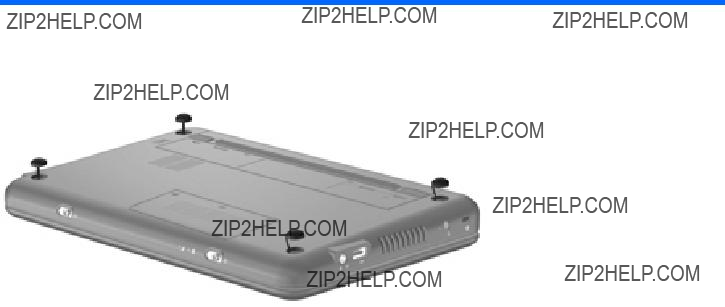
Device feet
The device feet are
Component replacement procedures 43
Battery
Before disassembling the device, follow these steps:
1.Shut down the device. If you are unsure whether the device is off or in Hibernation, turn the device on, and then shut it down through the operating system.
2.Disconnect all external devices connected to the device.
3.Disconnect the power from the device by first unplugging the power cord from the AC outlet and then unplugging the AC adapter from the device.
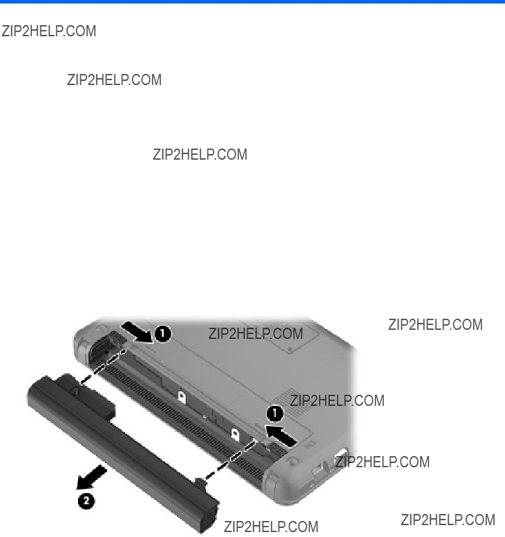
Remove the battery:
1.Turn the device
2.Slide the battery release latches (1) to release the battery.
3.Remove the battery (2).
Reverse this procedure to install a battery.
44 Chapter 4 Removal and replacement procedures
SIM
 NOTE: This section applies only to device models with WWAN capability.
NOTE: If there is a SIM inserted in the SIM slot, it must be removed before disassembling the computer. Be sure that the SIM is reinserted in the SIM slot after reassembling the computer.
Before removing the SIM, follow these steps:
1.Shut down the computer. If you are unsure whether the computer is off or in Hibernation, turn the computer on, and then shut it down through the operating system.
2.Disconnect all external devices connected to the computer.
3.Disconnect the power from the computer by first unplugging the power cord from the AC outlet and then unplugging the AC adapter from the computer.
4.Remove the battery (see Battery on page 44).
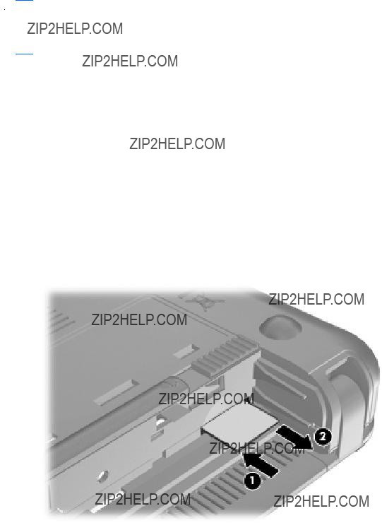
Remove the SIM:
1.Press in on the SIM (1). (The module is partially ejected from the SIM slot.)
2.Remove the SIM (2) from the SIM slot.
Reverse this procedure to insert the SIM.
Component replacement procedures 45

Memory module
Before removing the memory module, follow these steps:
1.Shut down the device. If you are unsure whether the device is off or in Hibernation, turn the device on, and then shut it down through the operating system.
2.Disconnect all external devices connected to the device.
3.Disconnect the power from the device by first unplugging the power cord from the AC outlet and then unplugging the AC adapter from the device.
4.Remove the battery (see Battery on page 44).
5.If your device has WWAN capability, remove the SIM (see SIM on page 45).
Remove the memory module:
1.Loosen the 2 Phillips 2.0??3.0 captive screws (1) that secure the memory module compartment cover to the computer.
2.Swing the cover up and away from the inside of the computer (2), and then remove the cover (3).
3.Spread the retaining tabs (1) on each side of the memory module slot to release the memory module. (The edge of the module opposite the slot rises away from the device.)
46 Chapter 4 Removal and replacement procedures
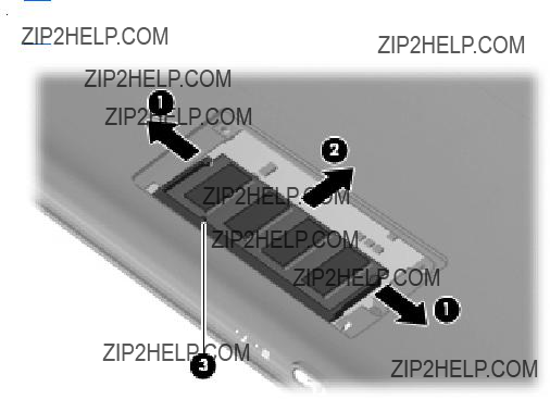
4.Remove the memory module (2) by pulling the module away from the slot at an angle.
 NOTE: Memory modules are designed with a notch (3) to prevent incorrect insertion into the memory module slot.
Reverse this procedure to install a memory module.
Component replacement procedures 47

Keyboard
48 Chapter 4 Removal and replacement procedures

Component replacement procedures 49

Before removing the keyboard, follow these steps:
1.Shut down the device. If you are unsure whether the device is off or in Hibernation, turn the device on, and then shut it down through the operating system.
2.Disconnect all external devices connected to the device.
3.Disconnect the power from the device by first unplugging the power cord from the AC outlet and then unplugging the AC adapter from the device.
4.Remove the battery (see Battery on page 44).
5.If your device has WWAN capability, remove the SIM (see SIM on page 45).
50 Chapter 4 Removal and replacement procedures
Remove the keyboard:
1.Remove the 3 Phillips SP2.0??3.0 screws that secure the keyboard to the device.
2.Turn the device
3.Turn the device upside down, and locate the keyboard release access on the bottom of the computer, inside the battery bay.
4.Insert a flexible tool into the opening, and then press inward to release the keyboard.
5.Turn the device
Component replacement procedures 51

6.Slide the keyboard back until its top edge rests on the display assembly (2).
7.Release the zero insertion force (ZIF) connector (1) to which the keyboard cable is attached.
8.Disconnect the cable (2), and then remove the keyboard.
9.Remove the keyboard.
Reverse this procedure to install the keyboard.
52 Chapter 4 Removal and replacement procedures
RTC battery
Before removing the
1.Shut down the device. If you are unsure whether the device is off or in Hibernation, turn the device on, and then shut it down through the operating system.
2.Disconnect all external devices connected to the device.
3.Disconnect the power from the device by first unplugging the power cord from the AC outlet and then unplugging the AC adapter from the device.
4.Remove the battery (see Battery on page 44).
5.If your device has WWAN capability, remove the SIM (see SIM on page 45).
6.Remove the Keyboard (see Keyboard on page 48).
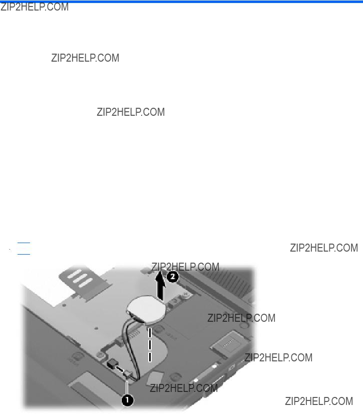
Remove the RTC battery:
1.Disconnect the RTC battery cable (1) from the system board.
2.Detach the RTC battery (2) from the system board.
 NOTE: The RTC battery is attached to the system board with
Reverse this procedure to install the RTC battery.
Component replacement procedures 53

Mass storage devices
 NOTE: Each hard drive spare part kit and
Before removing the hard drive or
1.Shut down the device. If you are unsure whether the device is off or in Hibernation, turn the device on, and then shut it down through the operating system.
2.Disconnect all external devices connected to the device.
3.Disconnect the power from the device by first unplugging the power cord from the AC outlet and then unplugging the AC adapter from the device.
4.Remove the battery (see Battery on page 44).
5.If your device has WWAN capability, remove the SIM (see SIM on page 45).
6.Remove the keyboard (see Keyboard on page 48).
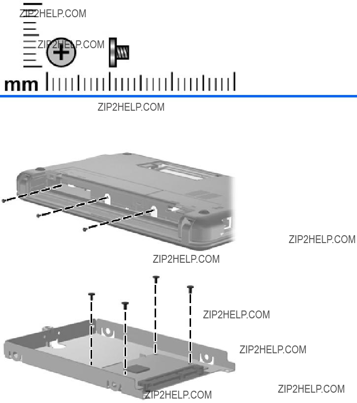
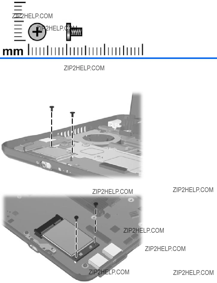
To remove the mass storage assembly:
1.Loosen the Phillips SP2.5??10.0 captive screw (1), and remove the two Phillips PM2.0??5.0 screws (2) that secure the assembly to the device.
54 Chapter 4 Removal and replacement procedures

2.Use the Mylar tab to slide the assembly to the left (3) to disconnect it, and remove the assembly (4).
Continue with one of the following sections for hard drive or
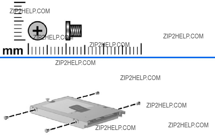
Hard drive
1.Remove the 4 Phillips SP3.0??4.0 screws (1) that secure the hard drive bracket to the hard drive.
2.Using the Mylar tab, lift the bracket (2) away from the hard drive.
Reverse this procedure to install a hard drive.
To remove the
1.Remove the 4 Phillips SP2.0??3.0 screws (1) that secure the
Component replacement procedures 55

2.Lift the
Reverse this procedure to install a
56 Chapter 4 Removal and replacement procedures

Top cover
Before removing the top cover, follow these steps:
1.Shut down the device. If you are unsure whether the device is off or in Hibernation, turn the device on, and then shut it down through the operating system.
2.Disconnect all external devices connected to the device.
3.Disconnect the power from the device by first unplugging the power cord from the AC outlet and then unplugging the AC adapter from the device.
4.Remove the battery (see Battery on page 44).
5.If your device has WWAN capability, remove the SIM (see SIM on page 45).
6.Remove the memory module (see Memory module on page 46).
7.Remove the keyboard (see Keyboard on page 48).
8.Remove the hard drive or
1.Turn the device upside down, with the front toward you.
2.Use a thin, flat tool to release the 4 tethered rubber feet.
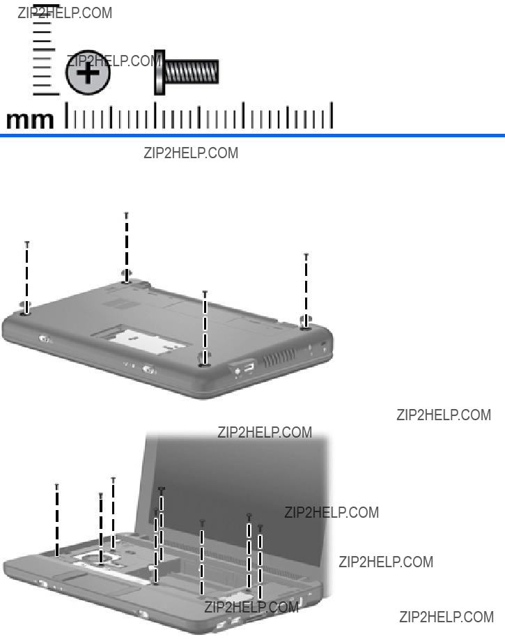
3.Remove the four Phillips PM2.5??7.0 screws (1), and the Phillips SP2.0??5.0 screw (2) that secure the top cover to the base enclosure.
Component replacement procedures 57
4.Turn the device
5.Open the device as far as possible.
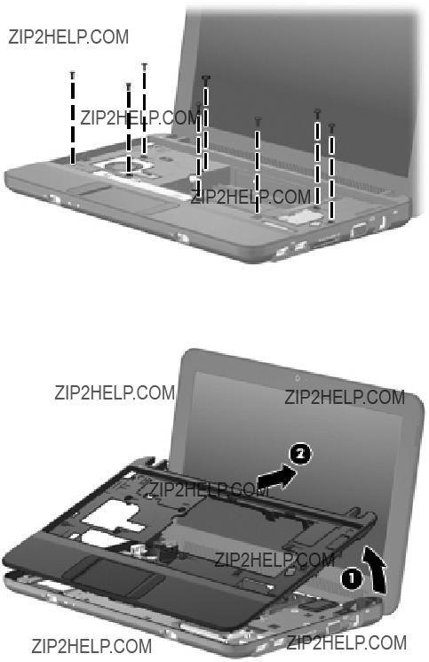
6.Remove the 8 Phillips PM2.5??7.0 screws that secure the top cover to the base enclosure.
7.Lift the inside edge of the top cover (1) and swing it up. Then slide the top cover back slightly to rest against the display assembly (2) at an angle.
8.Release the ZIF connector (1) to which the TouchPad button board cable is connected.
58 Chapter 4 Removal and replacement procedures
9.Disconnect the TouchPad button board cable (2) from the system board, and then remove the top cover.
Reverse this procedure to install the top cover.
Component replacement procedures 59

WLAN module
the British Virgin Islands, Brunei, Bulgaria, Burkina Faso, Burundi, Cameroon, Cape Verde,
the Central African Republic, Chad, Chile, Colombia, Comoros, the Congo, Costa Rica, Croatia, Cyprus, the Czech Republic, Denmark, Djibouti, Dominica, the Dominican Republic, East Timor, Ecuador, Egypt, El Salvador, Equatorial Guinea, Eritrea, Estonia, Ethiopia, Fiji, Finland, France, French Guiana, Gabon, Gambia, Georgia, Germany, Ghana, Gibraltar, Greece, Grenada, Guadeloupe, Guatemala, Guinea,
the People's Republic of China, Peru, the Philippines, Poland, Portugal, the Republic of Moldova, Romania, Russia, Rwanda, Samoa, San Marino, Sao Tome and Principe, Saudi Arabia, Senegal, Serbia, the Seychelles, Sierra Leone, Singapore, Slovakia, Slovenia, the Solomon Islands, Somalia, South Africa, South Korea, Spain, Sri Lanka, St. Kitts and Nevis, St. Lucia,
St. Vincent and the Grenadines, Suriname, Swaziland, Sweden, Switzerland, Taiwan, Tajikistan, Tanzania, Togo, Tonga, Trinidad and Tobago, Tunisia, Turkey, Turkmenistan, Tuvalu, Uganda, Ukraine, the United Arab Emirates, the United Kingdom, Uruguay, Uzbekistan, Vanuatu, Venezuela, Vietnam, Yemen, Zaire, Zambia, and Zimbabwe
60 Chapter 4 Removal and replacement procedures
CAUTION: The WWAN module and the WLAN module are not interchangeable.
To prevent an unresponsive system, replace the wireless module only with a wireless module authorized for use in the device by the governmental agency that regulates wireless devices in your country or region. If you replace the module and then receive a warning message, remove the module to restore device functionality, and then contact technical support through Help and Support.
Before removing the WLAN module, follow these steps:
1.Shut down the device. If you are unsure whether the device is off or in Hibernation, turn the device on, and then shut it down through the operating system.
2.Disconnect all external devices connected to the device.
3.Disconnect the power from the device by first unplugging the power cord from the AC outlet and then unplugging the AC adapter from the device.
4.Remove the battery (see Battery on page 44).
5.If your device has WWAN capability, remove the SIM (see SIM on page 45).
6.Remove the following components:
a.Keyboard (see Keyboard on page 48)
b.Hard drive or
c.Top cover (see Top cover on page 57)
Remove the WLAN module:
1.Remove the 2 Phillips PM2.0??4.0 screws (1) that secure the WLAN module to the system board. (The edge of the module opposite the slot rises away from the device.)
2.Disconnect the wireless antenna cables (2) from the terminals on the WLAN module.
3.Remove the WLAN module (3) by pulling the module away from the slot at an angle.
Reverse this procedure to install the WLAN module.
Component replacement procedures 61

WWAN module
 NOTE: Not available for computers with Mobile Mi installed.
 CAUTION: The WWAN module and the WLAN module are not interchangeable.
To prevent an unresponsive system, replace the wireless module only with a wireless module authorized for use in the device by the governmental agency that regulates wireless devices in your country or region. If you replace the module and then receive a warning message, remove the module to restore device functionality, and then contact technical support.
Before removing the WWAN module, follow these steps:
1.Shut down the device. If you are unsure whether the device is off or in Hibernation, turn the device on, and then shut it down through the operating system.
2.Disconnect all external devices connected to the device.
3.Disconnect the power from the device by first unplugging the power cord from the AC outlet and then unplugging the AC adapter from the device.
4.Remove the battery (see Battery on page 44).
5.Remove the SIM (see SIM on page 45).
6.Remove the following components:
a.Keyboard (see Keyboard on page 48)
b.Hard drive or
c.Top cover (see Top cover on page 57)
Remove the WWAN module:
1.Remove the 2 Phillips PM2.0??4.0 screws (1) that secure the WWAN connector module (3) to the system board. (The edge of the module opposite the slot rises away from the device.)
2.Disconnect the wireless antenna cables (2) from the terminals on the WWAN module.
 NOTE: The red WWAN antenna cable is connected to the WWAN module ???Main??? terminal. The blue WWAN antenna cable is connected to the WWAN module ???Aux??? terminal.
62 Chapter 4 Removal and replacement procedures

3.Remove the WWAN module (3) by pulling the module away from the slot at an angle.
Reverse this procedure to install the WWAN module.
Component replacement procedures 63

USB/audio board
Before removing the USB/audio board, follow these steps:
1.Shut down the computer. If you are unsure whether the computer is off or in Hibernation, turn the computer on, and then shut it down through the operating system.
2.Disconnect all external devices connected to the computer.
3.Disconnect the power from the computer by first unplugging the power cord from the AC outlet and then unplugging the AC Adapter from the computer.
4.Remove the battery (see Battery on page 44).
5.If your device has WWAN capability, remove the SIM (see SIM on page 45).
6.Remove the following components:
a.Keyboard (see Keyboard on page 48).
b.Hard drive or
c.Top cover (see Top cover on page 57).
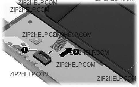
Remove the USB board:
1.Release the ZIF connector (1) to which the USB/audio board cable is connected, and disconnect the cable (2).
2.Release the USB/audio board from the clip attached to the base enclosure (3), and remove the USB/audio board (4).
64 Chapter 4 Removal and replacement procedures
Reverse this procedure to install the USB/audio board.
Component replacement procedures 65

Power/battery
Before removing the power/battery
1.Shut down the device. If you are unsure whether the device is off or in Hibernation, turn the device on, and then shut it down through the operating system.
2.Disconnect all external devices connected to the device.
3.Disconnect the power from the device by first unplugging the power cord from the AC outlet and then unplugging the AC adapter from the device.
4.Remove the battery (see Battery on page 44).
5.If your device has WWAN capability, remove the SIM (see SIM on page 45).
6.Remove the following components:
a.Keyboard (see Keyboard on page 48)
b.Hard drive or
c.Top cover (see Top cover on page 57)
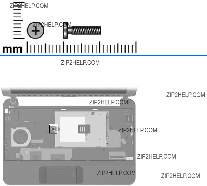
Remove the power/battery
1.Disconnect the power cable (1).
2.Remove the 2 Phillips BP2.5??5.0 screws (2) that secure the power/battery
66 Chapter 4 Removal and replacement procedures
3.Remove the power/battery
Reverse this procedure to install the power/battery
Component replacement procedures 67

Fan
 NOTE: To properly ventilate the device, allow at least a
Before removing the fan, follow these steps:
1.Shut down the device. If you are unsure whether the device is off or in Hibernation, turn the device on, and then shut it down through the operating system.
2.Disconnect all external devices connected to the device.
3.Disconnect the power from the device by first unplugging the power cord from the AC outlet and then unplugging the AC adapter from the device.
4.Remove the battery (see Battery on page 44).
5.If your device has WWAN capability, remove the SIM (see SIM on page 45).
6.Remove the following components:
a.Keyboard (see Keyboard on page 48)
b.Hard drive or
c.Top cover (see Top cover on page 57)
Remove the fan:
1.Disconnect the fan cable (1).
2.Remove the 2 Phillips PM2.5??5.0 screws (2) that secure the fan to the base enclosure.
68 Chapter 4 Removal and replacement procedures

3.Remove the fan (3).
Reverse this procedure to install the fan.
Component replacement procedures 69

Heat sink assembly
Before removing the heat sink assembly, follow these steps:
1.Shut down the device. If you are unsure whether the device is off or in Hibernation, turn the device on, and then shut it down through the operating system.
2.Disconnect all external devices connected to the device.
3.Disconnect the power from the device by first unplugging the power cord from the AC outlet and then unplugging the AC adapter from the device.
4.Remove the battery (see Battery on page 44).
5.If your device has WWAN capability, remove the SIM (see SIM on page 45).
6.Remove the following components:
a.Keyboard (see Keyboard on page 48)
b.Hard drive or
c.Top cover (see Top cover on page 57)
d.WLAN module (see WLAN module on page 60)
e.Fan (see Fan on page 68)
Remove the heat sink assembly:
1.Remove the 4 Phillips SP1.5??1.05 screws (1) that secure the heat sink assembly to the system board.
 NOTE: The screws are numbered 1 through 4. Follow this order when removing the screws.
70 Chapter 4 Removal and replacement procedures
2.Remove the heat sink assembly (2).
 NOTE: Due to the adhesive quality of the thermal material located between the heat sink assembly and system board components, it may be necessary to move the heat sink assembly from side to side to detach the assembly.
 NOTE: The thermal material must be thoroughly cleaned from the surfaces of the heat sink assembly and the system board each time the heat sink assembly is removed. Thermal paste is used on the processor (1), and thermal tape is used on the Northbridge chip (2). Replacement thermal material is included with all heat sink assembly and system board spare part kits.
Reverse this procedure to install the heat sink assembly.
Component replacement procedures 71

System board
Before removing the system board, follow these steps:
1.Shut down the device. If you are unsure whether the device is off or in Hibernation, turn the device on, and then shut it down through the operating system.
2.Disconnect all external devices connected to the device.
3.Disconnect the power from the device by first unplugging the power cord from the AC outlet and then unplugging the AC adapter from the device.
4.Remove the battery (see Battery on page 44).
5.If your device has WWAN capability, remove the SIM (see SIM on page 45).
6.Remove the following components:
a.Keyboard (see Keyboard on page 48)
b.Hard drive or
c.Top cover (see Top cover on page 57)
When replacing the system board, be sure that the following components are removed from the defective system board and installed on the replacement system board:
???WLAN module (see WLAN module on page 60)
???WWAN module, if included (see WWAN module on page 62)
???RTC battery (see RTC battery on page 53)
???Heat sink assembly (see Heat sink assembly on page 70)
72 Chapter 4 Removal and replacement procedures

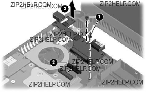
Remove the system board:
1.Release the tape securing the WWAN antennas (1).
2.Disconnect the following cables from the system board:
(2)Display panel cable
(3)Microphone cable
(4)Speaker cable
(5)WLAN cables
(6)WWAN cables (select models only)
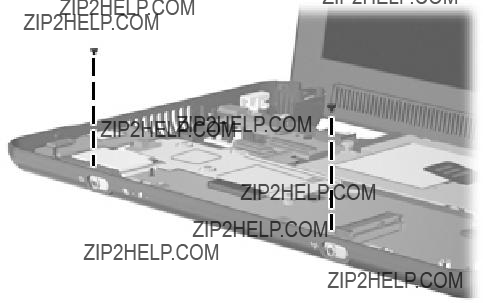
3.Remove the 2 Phillips PM1.5??2.0 screws (1) that secure the actuators for the power switch and wireless on/off switch to the system board.
4.Remove the actuators (2).
Component replacement procedures 73
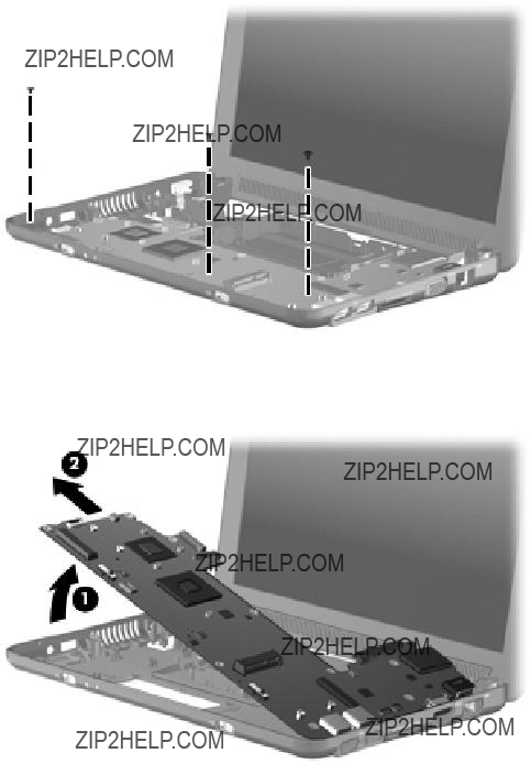
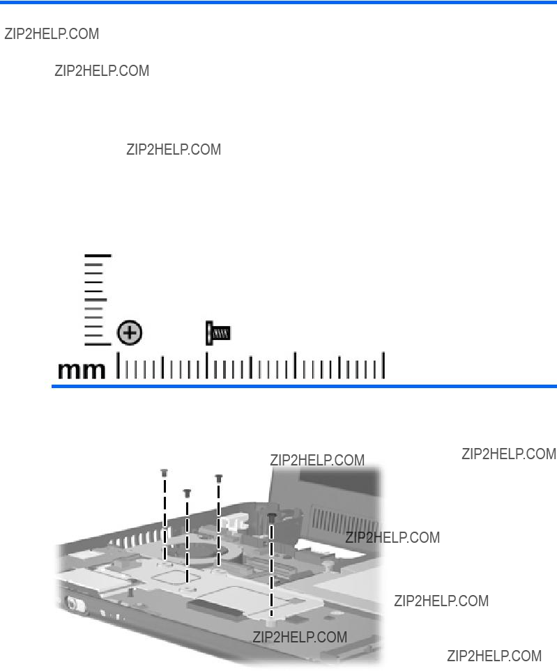
5.Remove the 3 Phillips PM2.5??5.0 screws that secure the system board to the base enclosure.
6.Grasp the system board at the midpoint of the left side (1), and lift it up.
7.Pull the system board (2) out to the left at an angle to remove it.
8.Remove the system board.
Reverse the procedure to install the system board.
74 Chapter 4 Removal and replacement procedures

Display assembly
 NOTE: Each display assembly spare part kit includes 1 webcam, 1 microphone, 1 speaker box, and 2 WLAN antenna transceivers/cables; WWAN on select models only.
Component replacement procedures 75

Before removing the display assembly, follow these steps:
1.Shut down the device. If you are unsure whether the device is off or in Hibernation, turn the device on, and then shut it down through the operating system.
2.Disconnect all external devices connected to the device.
3.Disconnect the power from the device by first unplugging the power cord from the AC outlet and then unplugging the AC adapter from the device.
4.Remove the battery (see Battery on page 44).
76 Chapter 4 Removal and replacement procedures

5.If your device has WWAN capability, remove the SIM (see SIM on page 45).
6.Remove the following components:
a.Keyboard (see Keyboard on page 48)
b.Hard drive or
c.Top cover (see Top cover on page 57)
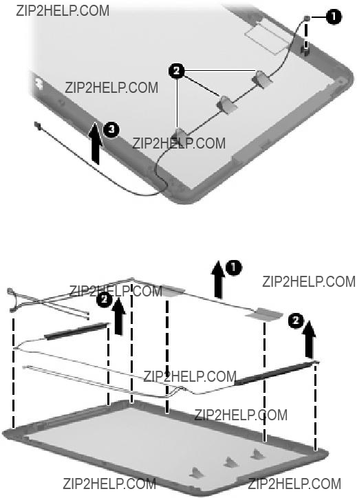
Remove the display assembly:
1.Release the tape securing the WWAN antennas (1).
2.Disconnect the following cables from the system board:
(2)Display panel cable
(3)Microphone cable
(4)Speaker cable
(5)WLAN cables
(6)WWAN cables (select models only)
 CAUTION: Support the display assembly when removing the following screws. Failure to support the display assembly can result in damage to the display assembly and other device components.
3.Remove the 4 Phillips PM2.5??5.0 screws (1) that secure the display assembly to the device.
 NOTE: One screw on the left hinge (2) also secures the display panel cable ground strap.
Component replacement procedures 77

4.Remove the display assembly (3).
5.If it is necessary to replace the display bezel, perform the following steps:
a.Remove the display hinge covers (1).
b.Flex the inside edges of the top and bottom (2), and then the left and right sides (3) of the display bezel until the bezel disengages from the display enclosure.
c.Remove the display bezel (4).
78 Chapter 4 Removal and replacement procedures
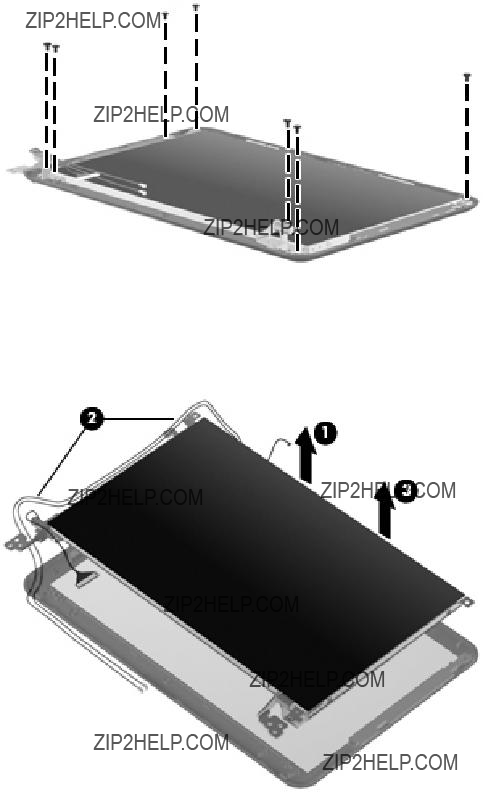
6.If it is necessary to replace the display panel, perform the following steps:
a.Remove the 7 Phillips PM2.0??3.0 screws that secure the display panel to the display enclosure.
b.Lift the display panel up from the display enclosure (1).
c.Disconnect the webcam cable (2) from the system board (2)
d.Remove the display panel (3) from the display enclosure.
7.If it is necessary to replace the speaker assembly, perform the following steps:
a.Remove the three Phillips PM2.0??3.0 screws (1) that secure the speaker assembly to the display enclosure.
Component replacement procedures 79
b.Remove the speaker assembly (2).
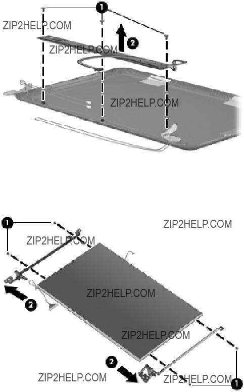
8.If it is necessary to replace the display hinges, perform the following steps:
a.Remove the 2 Phillips PM2.0??3.0 screws (1) that secure each hinge to the display enclosure.
b.Remove the hinges (2).
9.If it is necessary to replace the display panel cable, perform the following steps: a. Peel back the Mylar protection on the back of the display panel (1).
80 Chapter 4 Removal and replacement procedures
b.Disconnect the display panel cable (2).
10.If it is necessary to replace the webcam module, perform the following steps:
a.Disconnect the webcam cable (1) from the webcam.
b.Remove the webcam (2).
11.If it is necessary to replace the microphone receiver, perform the following steps:
a. Release the microphone receiver from the clip (1) that secures it to the display enclosure.
Component replacement procedures 81
b.Pull the receiver through the tabs (2), and remove the microphone receiver (3).
12.If it is necessary to replace the wireless antenna transceivers and cables, detach the cables from the adhesive (1) that secures them to the display enclosure, and then remove the cables (2).
Reverse this procedure to reassemble and install the display assembly.
82 Chapter 4 Removal and replacement procedures

5 Setup Utility
Starting the Setup Utility
The Setup Utility is a
The utility reports information about the device and provides settings for startup, security, and other preferences.
To start the Setup Utility:
???Open the Setup Utility by turning on or restarting the device, and then pressing f10 while the ???F10 = BIOS Setup Options??? message is displayed in the
Using the Setup Utility
Changing the language of the Setup Utility
The following procedure explains how to change the language of the Setup Utility. If the Setup Utility is not already running, begin at step 1. If the Setup Utility is already running, begin at step 2.
1.Open the Setup Utility by turning on or restarting the device, and then pressing f10 while the ???F10 = BIOS Setup Options??? message is displayed in the
2.Use the arrow keys to select System Configuration > Language, and then press enter.
3.Use the arrow keys to select a language, and then press enter.
4.When a confirmation prompt with your language selected is displayed, press enter.
5.To save your change and exit the Setup Utility, use the arrow keys to select Exit > Exit Saving Changes, and then press enter.
Your change goes into effect immediately.
Navigating and selecting in the Setup Utility
Because the Setup Utility is not operating
???To choose a menu or a menu item, use the arrow keys.
???To choose an item in a list or to toggle a field, for example an Enable/Disable field, use either the arrow keys or f5 or f6.
Starting the Setup Utility 83

???To select an item, press enter.
???To close a text box or return to the menu display, press esc.
???To display additional navigation and selection information while the Setup Utility is open, press f1.
Displaying system information
The following procedure explains how to display system information in the Setup Utility. If the Setup Utility is not open, begin at step 1. If the Setup Utility is open, begin at step 2.
1.Open the Setup Utility by turning on or restarting the device, and then pressing f10 while the ???F10 = BIOS Setup Options??? message is displayed in the
2.Select the Main menu. System information such as the system time and date, and identification information about the device is displayed.
3.To exit the Setup Utility without changing any settings, use the arrow keys to select Exit > Exit Discarding Changes, and then press enter.
Restoring default settings in the Setup Utility
The following procedure explains how to restore the Setup Utility default settings. If the Setup Utility is not already running, begin at step 1. If the Setup Utility is already running, begin at step 2.
1.Open the Setup Utility by turning on or restarting the device, and then pressing f10 while the ???F10 = BIOS Setup Options??? message is displayed in the
2.Use the arrow keys to select Exit > Load Setup Defaults, and then press enter.
3.When the Setup Confirmation is displayed, press enter.
4.To save your change and exit the Setup Utility, use the arrow keys to select Exit > Exit Saving Changes, and then press enter.
The Setup Utility default settings go into effect when the device restarts.
 NOTE: Your password, security, and language settings are not changed when you restore the factory default settings.
Exiting the Setup Utility
You can exit the Setup Utility with or without saving changes.
???To exit the Setup Utility and save your changes from the current session:
If the Setup Utility menus are not visible, press esc to return to the menu display. Then use the arrow keys to select Exit > Exit Saving Changes, and then press enter.
???To exit the Setup Utility without saving your changes from the current session:
If the Setup Utility menus are not visible, press esc to return to the menu display. Then use the arrow keys to select Exit > Exit Discarding Changes, and then press enter.
After either choice, the device restarts and loads the operating system.
84 Chapter 5 Setup Utility

Setup Utility menus
The menu tables in this section provide an overview of Setup Utility options.
 NOTE: Some of the Setup Utility menu items listed in this chapter may not be supported by your device.
Main menu
Security menu
System Configuration menu
Setup Utility menus 85

Diagnostics menu
86 Chapter 5 Setup Utility

6 Specifications
Device specifications
NOTE: Applicable product safety standards specify thermal limits for plastic surfaces. The device operates well within this range of temperatures.
Device specifications 87

88 Chapter 6 Specifications


Hard drive specifications
* 1 GB = 1 billion bytes when referring to hard drive storage capacity. Actual accessible capacity is less. Actual drive specifications may differ slightly.
NOTE: Certain restrictions and exclusions apply. Contact technical support for details.
90 Chapter 6 Specifications
Performance

System DMA specifications
92 Chapter 6 Specifications

System interrupt specifications
System interrupt specifications 93

System I/O address specifications
94 Chapter 6 Specifications

System I/O address specifications 95

System memory map specifications
96 Chapter 6 Specifications
7 Screw listing
This section provides specification and reference information for the screws and screw locks used in the device. All screws listed in this section are available in the Screw Kit, spare part number
Phillips PM1.5??1.0 screw
Where used: 4 screws that secure the heat sink to the system board
Phillips PM1.5??1.0 screw 97
Where used: Two screws that secure the power and wireless switch actuators to the base enclosure
98 Chapter 7 Screw listing
Phillips PM2.0??3.0 screw
Where used: 3 screws that secure the keyboard to the device
Where used: Four screws that secure the
Phillips PM2.0??3.0 screw 99

Where used: Seven screws that secure the display panel to the display enclosure
Where used: Three screws that secure the speaker assembly to the display enclosure
Where used: Four screws that secure the hinges to the display panel
100 Chapter 7 Screw listing
Phillips PM2.0??3.0 captive screw
Phillips PM2.0??3.0 captive screw 101
Phillips PM2.0??4.0 screw
Where used: Two screws that secure the WLAN module to the system board
Where used: Two screws that secure the WWAN to the system board
102 Chapter 7 Screw listing

Phillips PM2.0??5.0 screw
Where used: Two screws that secure the hard drive or
Where used: One screw that secures the top cover to the base enclosure
Phillips PM2.0??5.0 screw 103

Phillips PM2.5??5.0 screw
Where used: Two screws that secure the power/battery
Where used: Four screws that secure the display assembly and top cover to the device
104 Chapter 7 Screw listing

Where used: Two screws that secure the fan to the system board
Where used: Three screws that secure the system board to the base enclosure
Where used: Four screws that secure the display assembly to the base enclosure
Phillips PM2.5??5.0 screw 105
Phillips PM2.5??7.0 screw
Where used: Four screws that secure the top cover to the base enclosure
Where used: Eight screws that secure the top cover to the base enclosure
106 Chapter 7 Screw listing
Phillips PM2.5??10.0 captive screw
Where used: One captive screw, with a
Phillips PM2.5??10.0 captive screw 107
Phillips PM3.0??4.0 screw
Where used: Four screws that secure the hard drive bracket to the hard drive
108 Chapter 7 Screw listing

8 Backup and recovery
Select the section in this chapter that applies to the operating system installed on your computer.
109

Mobile Mi backup and recovery
Use the instructions in this section if Mobile Mi is installed on your computer.
To protect your information, back up your files and folders. Then if the system fails, you can restore your important files from copies. You can also use the options listed in this section to restore the operating system and programs that were installed at the factory.
Backing up your information
Successful recovery after a system failure depends on whether you have completely backed up your files. You should back up your files on a regular basis to maintain
You can back up important personal files and folders to the Mini Mobile Drive (select models only), to an external hard drive, or to a USB flash drive (purchased separately).
When to back up
???On a regular basis
???Before the system is repaired or restored
???Before you add or modify hardware or software
Restoring your information
In case of system failure or instability, you can restore the operating system and programs installed at the factory.
CAUTION: The restore process reformats hard drive, completely erasing all information. All the files you have created and any software installed on the device are permanently removed. The restore process reinstalls the original operating system, software, and drivers. Software, drivers, and updates not installed with the factory image must be reinstalled using Update Manager.
The device provides the following restore options:
???System Restore (installed on the device): You can use the System Restore utility to restore the original operating system and programs.
???HP Mi Restore Image Creator (USB flash drive): If you are unable to boot (start up) the device, and if you are unable to use System Restore, you can use another computer to download the HP Mi Restore Image Creator utility and create a bootable USB flash drive (purchased separately). You can then use the USB flash drive to install the HP Mi recovery image and programs on your device.
Note the following before beginning the restore process:
???The device must be connected to AC power during the restore process.
???The restore process may take several hours to complete.
???If possible, all personal files should be backed up.
110 Chapter 8 Backup and recovery
Using System Restore
 NOTE: System Restore is the recommended option to restore the original operating system.
To restore the original operating system and programs using the System Restore utility that is installed on the device, follow these steps:
1.Turn on or restart the device, and then press the esc key repeatedly while the ???F10 = BIOS Setup Options??? message is displayed in the
The ???System Restore??? page opens.
2.Use the arrow keys to select System Restore, and then press enter.
3.Follow the
Using HP Mi Restore Image Creator
 NOTE: Use HP Mi Restore Image Creator if you are unable to boot (start up) the device, and if you are unable to use System Restore.
You will need the following before you begin this restore process:
???A
 NOTE: This USB flash drive should have bootable capability. Refer to the USB flash drive manufacturer for additional information.
???An additional computer running either a Windows?? or Linux operating system
To perform this restore option, you download the HP Mi Restore Image Creator utility and Mini operating system onto another computer and then transfer the necessary files to the USB flash drive. The drive can then be used to reboot your device and restore the system.
Follow the specific operating system instructions in this section to restore your system.
 CAUTION: The restore process reformats and completely erases the hard drive on the Mini. All the files you have created and any software installed on the device are permanently removed. The restore process reinstalls the original operating system, software, and drivers. Software, drivers, and updates not installed with the factory image must be reinstalled using Update Manager.
Restoring using a Windows computer
To download the files to a computer running a Windows operating system and then restore your device, follow these steps:
1.From your Windows computer, go to http://www.hp.com.
2.Select the Support & Drivers tab.
3.Under ???Step 1: Start by selecting a task,??? select Download drivers and software (and firmware) .
4.Under ???Step 2: Enter a product name / number,??? type the part number/product number (p/n) of your Mini, and then select Go.
 NOTE: The p/n is located on the service tag affixed to the bottom of your Mini.
5.Under ???Which operating system is used with your product???? select HP Mi or Linux .
Mobile Mi backup and recovery 111

6.Select HP Mi Restore Image Creator (for Windows).
7.Select Download only.
8.Save ImageCreator.msi to the Windows computer.
9.
10.Insert the USB flash drive into a USB port on the Windows computer.
CAUTION: The restore process reformats and completely erases the USB flash drive. All the files on the USB flash drive are permanently removed.
11.Launch HP Mi Restore Image Creator from the Start menu.
12.Select Download HP Mini recovery image.
13.Select the target USB flash drive, and then select Start to download the latest Mini recovery image from the HP Web site.
The recovery image will be downloaded and saved to the Windows computer and then written to the USB flash drive.
14.When the download and write processes are complete, remove the USB flash drive.
15.Insert the USB flash drive into a USB port on your Mini.
16.Change the boot order by turning on or restarting the device, and then pressing f9 repeatedly while the ???F9 = Change Boot Device Order??? message is displayed in the
17.Use the arrow keys to select the USB flash drive, and then press enter.
18.Press enter again to begin restoring the device.
19.Follow the
20.After the operating system and programs are installed, remove the USB flash drive.
 NOTE: After the operating system and programs are installed, the device automatically restarts. You are then prompted to set up your device.
21.Use Update Manager to reinstall any updates not installed with the factory image.
22.Restore your personal files.
 NOTE: After this process is complete, you can uninstall the HP Mi Restore Image Creator utility from the Windows computer and delete the downloaded recovery image from the USB flash drive. (The image must be deleted manually.)
Restoring using a Linux computer
To download the files to a computer running a Linux operating system and then restore your device, follow these steps:
1.From your Linux computer, go to http://www.hp.com.
2.Select the Support & Drivers tab.
112 Chapter 8 Backup and recovery

3.Under ???Step 1: Start by selecting a task,??? select Download drivers and software (and firmware) .
4.Under ???Step 2: Enter a product name / number,??? type the part number/product number (p/n) of your Mini, and then select Go.
 NOTE: The p/n is located on the service tag affixed to the bottom of your Mini.
5.Under ???Which operating system is used with your product???? select HP Mi or Linux .
6.Select HP Mi Restore Image Creator (for Linux).
7.Select Download only.
8.Save
9.Install
10.Insert the USB flash drive into a USB port on the Linux computer
 CAUTION: The restore process reformats and completely erases the USB flash drive. All the files on the USB flash drive are permanently removed.
11.Open a terminal window and type the following command at the command prompt: sudo
12.Select Download restore image/HP Mi Restore Image.
13.Select the target USB flash drive, and then select Start to download the latest Mini recovery image from the HP Web site.
The recovery image will be downloaded and saved to the Linux computer, and then written to the USB flash drive.
14.When the download and write processes are complete, remove the USB flash drive.
15.Insert the USB flash drive into a USB port on your Mini.
16.Change the boot order by turning on or restarting the device, and then pressing f9 repeatedly while the ???F9 = Change Boot Device Order??? message is displayed in the
17.Use the arrow keys to select the USB flash drive, and then press enter.
18.Press enter again to begin restoring the device.
19.Follow the
20.After the operating system and programs are installed, remove the USB flash drive.
 NOTE: After the operating system and programs are installed, the device automatically restarts. You are then prompted to set up your device.
21.Use Update Manager to reinstall any updates not installed with the factory image.
22.Restore your personal files.
 NOTE: After this process is complete, you can uninstall the HP Mi Restore Image Creator utility from the Linux computer and delete the downloaded recovery image from the USB flash drive. (The image must be deleted manually.)
Mobile Mi backup and recovery 113

Windows 7 backup and recovery
Use the instructions in the section if Windows 7 is installed on your computer.
To protect your information, back up your files and folders. In case of system failure, you can use the backup files to restore your computer.
CAUTION: In the event of a hard drive failure, you cannot use your computer to access the Disaster Recovery utility. Therefore, HP recommends that you download the Disaster Recovery utility SoftPaq, and then extract it to a USB flash drive as soon as possible after software setup. For details, refer to ???Downloading and extracting the Disaster Recovery utility??? later in this chapter.
Depending on your computer model, you may have one of the following backup and recovery solutions:
???Roxio BackOnTrack
???HP Recovery Manager
 NOTE: For detailed information, perform a search for these topics in Help and Support.
Backing up and recovering using Roxio BackOnTrack
Successful recovery after a system failure depends on whether you have completely backed up your files. If Roxio BackOnTrack is preinstalled on your computer, BackOnTrack allows you to create a backup of your computer image. You should create the initial backup immediately after software setup. As you add new software and data files, you should continue to back up your system on a regular basis to maintain a reasonably current backup.
Note the following guidelines when backing up your information:
???Store personal files in the Documents library and back up this folder regularly.
???Back up templates stored in their associated programs.
???Save customized settings in a window, toolbar, or menu bar by taking a screen shot of your settings. The screen shot can be a
To copy the screen and paste it into a
1.Display the screen.
2.Copy the screen:
???To copy the active window, press alt+fn+prt sc.
???To copy the entire screen, press fn+prt sc.
3.Open a
4.Save the document.
Creating a copy of the hard drive
The back up drive function of BackOnTrack creates a Disaster Recovery Set that is an exact image of your hard drive data. You can back up the image to an external hard drive (purchased separately).
To create a Disaster Recovery Set using BackOnTrack, follow these steps:
114 Chapter 8 Backup and recovery

 NOTE: Be sure that the computer is connected to AC power before you start the backup process.
1.Select Start>All Programs> Roxio.
2.SelectBackOnTrack>BackOnTrack Home>Disaster Recovery.
3.Select Backup drive.
4.Select a drive to back up.
5.Add a comment to describe the backup.
 NOTE: Comments are optional, but adding comments can help you remember the purpose of the backup. The date and list of drives being backed up are automatically included in the description.
6.Select a destination for the Disaster Recovery Set.
 NOTE: The destination cannot be a network drive.
7.Select the action button at the
8.Follow the
Performing a recovery
In case of system failure or instability, the computer provides the following ways to recover your files:
???BackOnTrack Disaster Recovery utility: You can use Disaster Recovery to recover your hard drive image (including your files, programs, and operating system) after a hard drive failure.
???BackOnTrack Instant Restore utility: You can use Instant Restore to quickly restore your computer to a working state if a
 NOTE: For more information about computer system states, refer to the BackOnTrack software help.
Using the Disaster Recovery utility
 NOTE: To perform a recovery with Disaster Recovery, you need a USB flash drive (purchased separately). For optimum performance, the capacity of the drive should be no larger than 2 GB.
Disaster Recovery recovers data from a Disaster Recovery Set that you previously created with Roxio BackOnTrack. Disaster Recovery is available from the HP Web site in a compressed file called a
SoftPaq.
 NOTE: Running the SoftPaq makes the USB drive bootable.
 CAUTION: Before performing a disaster recovery, you must download the Disaster Recovery utility and extract it to a USB flash drive.
Downloading and extracting the Disaster Recovery utility
To download and extract Disaster Recovery, follow these steps:
1.Connect a bootable USB flash drive or external drive to a USB port on your computer.
2.Open your Web browser, go to http://www.hp.com/support, and select your country or region.
Windows 7 backup and recovery 115

3.Enter the SoftPaq number SP42226 in the Search box, press enter, and then follow the
4.Select Download only to save the file to your computer.
5.When prompted, select Save, and then select the external drive from the list of storage locations.
6.After the file is downloaded, navigate to the USB flash drive or external drive, and then double- click the SoftPaq file to format the USB flash drive and extract the Disaster Recovery files.
7.If prompted to do so, restart your computer after the installation is complete.
Restoring your hard drive image
To restore your hard drive image using Disaster Recovery, follow these steps:
1.Connect the external hard drive containing the Disaster Recovery Set to your computer.
2.Connect the bootable USB flash drive containing the extracted Disaster Recovery utility to a USB port on your computer.
3.Change the boot device order by turning on or restarting the computer, and then press f9.
4.Use the arrow keys to select the USB flash drive, and then press enter.
5.At the Roxio BackOnTrack Disaster Recovery screen, select Disaster Recovery>Next.
6.Browse to the external hard drive containing the Disaster Recovery Set, and then select Next.
7.Select Next to proceed with the recovery.
 NOTE: This process may take several minutes.
8.After a message on the screen reports a successful recovery, select Finish.
Using the Instant Restore utility
You can restore your computer from Windows when the operating system is functioning. If the operating system is not functioning, you can also access the utility by restarting your computer.
 NOTE: For more information about the Instant Restore utility, refer to the BackOnTrack software Help.
Using the Instant Restore utility when the operating system is functioning
To recover information when the operating system is functioning properly, follow these steps:
1.Save and close all open documents and close any open programs.
2.Select Start>All Programs>Roxio.
3.Select BackOnTrack>BackOnTrack Home>Instant Restore.
4.Select Restore State, and then select a restore state.
5.Select the action button in the
6.Select Yes to confirm your selected restore state.
When the restore process is complete, the computer restarts and a notification message is displayed.
116 Chapter 8 Backup and recovery

Using the Instant Restore utility when the operating system is not functioning
To recover information when the operating system is not functioning, follow these steps:
1.Restart the computer.
 NOTE: If the operating system has stopped responding and the computer screen is blue, restart the computer by turning the power switch off and then on.
2.When the computer logo (HP or Compaq) is displayed on the screen, press the f6 button repeatedly until the Windows status bar is displayed.
3.When the Roxio BackOnTrack screen is displayed, follow the
Using Windows Backup and Restore
To create a backup using Windows Backup and Restore, follow these steps:
 NOTE: Be sure that the computer is connected to AC power before you start the backup process.
NOTE: The backup process may take over an hour, depending on file size and the speed of the computer.
1.Select Start>All Programs>Maintenance>Backup and Restore.
2.Follow the
 NOTE: Windows includes the User Account Control feature to improve the security of your computer. You may be prompted for your permission or password for tasks such as installing software, running utilities, or changing Windows settings. Refer to Help and Support for more information.
Using system restore points
When you back up your system, you are creating a system restore point. A system restore point allows you to save and name a snapshot of your hard drive at a specific point in time. You can then revert back to that point if you want to reverse subsequent changes made to your system.
 NOTE: Recovering to an earlier restore point does not affect data files saved or
You also can create additional restore points to provide increased protection for your system files and settings.
When to create restore points
???Before you add or extensively modify software or hardware.
???Periodically, whenever the system is performing optimally.
 NOTE: If you revert to a restore point and then change your mind, you can reverse the restoration.
Creating a system restore point
1.Select Start>Control Panel>System and Security>System.
2.In the left pane, select System protection.
Windows 7 backup and recovery 117

3.Select the System Protection tab.
4.Under Protection Settings, select the disk for which you want to create a restore point.
5.Select Create.
6.Follow the
Restoring to a previous date and time
To revert to a restore point (created at a previous date and time) when the computer was functioning optimally, follow these steps:
1.Select Start>Control Panel>System and Security>System.
2.In the left pane, select System protection.
3.Select the System Protection tab.
4.Select System Restore.
5.Follow the
Backing up and recovering using HP Recovery Manager
If your computer includes HP Recovery Manager, tools provided by the operating system and by HP Recovery Manager software are designed to help you with the following tasks for safeguarding your information and restoring it in case of a system failure:
???Backing up your information
???Creating a set of recovery discs
???Creating system restore points
???Recovering a program or driver
???Performing a full system recovery
Backing up your information
As you add new software and data files, you should back up your system on a regular basis to maintain a reasonably current backup. Back up your system at the following times:
???At regularly scheduled times
 NOTE: Set reminders to back up your information periodically.
???Before the computer is repaired or restored
???Before you add or modify hardware or software Note the following when backing up:
???Create system restore points using the Windows System Restore feature, and periodically copy them to a disc.
???Store personal files in the Documents library, and periodically back up this folder.
???Back up templates stored in their associated programs.
118 Chapter 8 Backup and recovery

???You can back up your information to an optional external hard drive, a network drive, or discs.
???When backing up to discs, use any of the following types of discs (purchased separately):
 NOTE: DVDs store more information than CDs, so using them for backup reduces the number of recovery discs required.
???When backing up to discs, number each disc before inserting it into an optical drive.
???Save the customized settings in a window, toolbar, or menu bar by taking a screen shot of the settings. The screen shot can be a
To copy the screen and paste the image into a
1.Display the screen.
2.Copy the screen:
To copy only the active window, press alt+prt sc. To copy the entire screen, press prt sc.
3.Open a
4.Save the document.
Creating a set of recovery discs
HP recommends that you create recovery discs to be sure that you can restore your system to its original factory state if you experience serious system failure or instability. Create these discs after setting up the computer for the first time.
 NOTE: This task will require an optional external or shared optical drive.
Handle these discs carefully and keep them in a safe place. The software allows the creation of only one set of recovery discs.
Note the following guidelines before creating recovery discs:
???You will need
 NOTE:
NOTE:
???The computer must be connected to AC power during this process.
???Only one set of recovery discs can be created per computer.
???Number each disc before inserting it into an optical drive.
???If necessary, you can exit the program before you have finished creating the recovery discs. The next time you open Recovery Manager, you will be prompted to continue the disc creation process.
Windows 7 backup and recovery 119

To create a set of recovery discs:
1.Select Start>All Programs>Recovery Manager>Recovery Disc Creation.
2.Follow the
Performing a recovery
 NOTE: You can recover only files that you have previously backed up. HP recommends that you use Recovery Manager to create a set of recovery discs (entire drive backup) as soon as you set up your computer.
Recovery Manager software allows you to repair or restore the system if you experience system failure or instability. Recovery Manager works from recovery discs that you create or from a dedicated recovery partition (select models only) on the hard drive. However, computers that include a
 NOTE: Windows has its own
NOTE: Recovery Manager recovers only the software that was preinstalled at the factory. Software not provided with this computer must be downloaded from the manufacturer???s Web site or reinstalled from the disc provided by the manufacturer.
Recovering using the recovery discs
To restore the system from the recovery discs:
1.Back up all personal files.
2.Insert the first recovery disc into an optional optical drive, and restart the computer.
3.Follow the
Recovering using the partition on the hard drive (select models only)
On some models, you can perform a recovery from the partition on the hard drive, which is accessed by pressing either the Start button or f11. This restores the computer to its factory condition.
 NOTE: Computers with an SSD may not have a recovery partition. If the computer does not have a recovery partition, you will not be able to recover using this procedure. Recovery discs have been included for computers that do not have a partition. Use these discs to recover your operating system and software.
To restore the system from the partition, follow these steps:
1.Access Recovery Manager in either of the following ways:
Select Start>All Programs>Recovery Manager>Recovery Manager.
??? or ???
a.Turn on or restart the computer.
b.Press f11 while the ???Press f11 for recovery message is displayed on the screen.
120 Chapter 8 Backup and recovery
 NOTE: It may take several minutes for Recovery Manager to load.
2.In the Recovery Manager window, select System Recovery.
3.Follow the
Windows 7 backup and recovery 121

Windows Vista backup and recovery
Use the instructions in this section if Windows Vista is installed on your computer.
Backing up your information
Recovery after a system failure is as complete as your most current backup. You should create your initial backup immediately after software setup. As you add new software and data files, you should continue to back up your system on a regular basis to maintain a reasonably current backup.
You can back up your information to an optional external hard drive, a network drive, or discs.
Note the following when backing up:
???Store personal files in the Documents folder, and back it up regularly.
???Back up templates that are stored in their associated programs.
???Save customized settings that appear in a window, toolbar, or menu bar by taking a screen shot of your settings. The screen shot can be a
To create a screen shot:
1.Display the screen you want to save.
2.Copy the screen image:
To copy only the active window, press alt+fn+prt sc. To copy the entire screen, press fn+prt sc.
3.Open a
4.Save the document.
???When backing up to discs, use any of the following types of discs (purchased separately):
 NOTE: DVDs and DVDs with
??? When backing up to discs, number each disc before inserting it into the optical drive of the computer. To create a backup using Backup and Restore Center, follow these steps:
 NOTE: Be sure that the computer is connected to AC power before you start the backup process.
NOTE: The backup process may take over an hour, depending on file size and the speed of the computer.
1.Select Start > All Programs > Maintenance > Backup and Restore Center.
2.Follow the
122 Chapter 8 Backup and recovery

 NOTE: Windows?? includes the User Account Control feature to improve the security of your computer. You may be prompted for your permission or password for tasks such as installing software, running utilities, or changing Windows settings. Refer to Help and Support for more information.
Performing a recovery
In case of system failure or instability, the computer provides the following tools to recover your files:
???Windows recovery tools: You can use the Backup and Restore Center to recover information you have previously backed up. You can also use Windows Startup Repair to fix problems that might prevent Windows from starting correctly.
???f11 recovery tools: You can use the f11 recovery tools to recover your original hard drive image. The image includes the Windows operating system and software programs installed at the factory.
 NOTE: If you are unable to boot (start up) your computer, you must purchase a Windows Vista?? operating system DVD to reboot the computer and repair the operating system. For additional information, refer to the ???Using a Windows Vista operating system DVD (purchased separately)??? section in this guide.
Windows Vista backup and recovery 123

Using the Windows recovery tools
To recover information you previously backed up, follow these steps:
1.Select Start > All Programs > Maintenance > Backup and Restore Center.
2.Follow the
 NOTE: Windows includes the User Account Control feature to improve the security of your computer. You may be prompted for your permission or password for tasks such as installing software, running utilities, or changing Windows settings. Refer to Help and Support for more information.
To recover your information using Startup Repair, follow these steps:
 CAUTION: Using Startup Repair completely erases hard drive contents and reformats the hard drive. All files you have created and any software installed on the computer are permanently removed. When reformatting is complete, the recovery process restores the operating system, as well as the drivers, software, and utilities from the backup used for recovery.
1.If possible, back up all personal files.
2.If possible, check for the presence of the Windows partition and the HP Recovery partition. To find the partitions, select Start > Computer.
 NOTE: If the Windows partition and the HP Recovery partition have been deleted, you must recover your operating system and programs using the Windows Vista operating system DVD and the Driver Recovery disc (both purchased separately). For additional information, refer to the ???Using a Windows Vista operating system DVD (purchased separately)??? section in this guide.
3.Restart the computer, and then press f8 before the Windows operating system loads.
4.Select Repair your computer.
5.Follow the
 NOTE: For additional information on recovering information using the Windows tools, perform a search for these topics in Help and Support.
124 Chapter 8 Backup and recovery

Using f11
CAUTION: Using f11 completely erases hard drive contents and reformats the hard drive. All files you have created and any software installed on the computer are permanently removed. The f11 recovery tool reinstalls the operating system and HP programs and drivers that were installed at the factory.
Software not installed at the factory must be reinstalled.
To recover the original hard drive image using f11, follow these steps:
1.If possible, back up all personal files.
2.If possible, check for the presence of the HP Recovery partition. To find the partition, select
Start > Computer.
 NOTE: If the HP Recovery partition has been deleted, you must recover your operating system and programs using the Windows Vista operating system DVD and the Driver Recovery disc (both purchased separately). For additional information, refer to the ???Using a Windows Vista operating system DVD (purchased separately)??? section in this guide.
3.Turn on or restart the computer, and then press esc while the ???Press the ESC key for Startup Menu??? message is displayed at the bottom of the screen.
4.Press f11 while the ???Press <F11> for recovery??? message is displayed on the screen.
5.Follow the
Using a Windows Vista operating system DVD (purchased separately)
If you are unable to boot (start up) your computer, you must purchase a Windows Vista operating system DVD to reboot the computer and repair the operating system. Make sure that your most recent backup (stored on discs or on an external drive) is easily accessible. To order a Windows Vista operating system DVD, go to http://www.hp.com/support, select your country or region, and follow the
 CAUTION: Using a Windows Vista operating system DVD completely erases hard drive contents and reformats the hard drive. All files you have created and any software installed on the computer are permanently removed. When reformatting is complete, the recovery process helps you restore the operating system, as well as drivers, software, and utilities.
To initiate recovery using a Windows Vista operating system DVD, follow these steps:
 NOTE: This process takes several minutes.
1.If possible, back up all personal files.
2.Restart the computer, and then insert the Windows Vista operating system DVD into the optical drive before the Windows operating system loads.
3.When prompted, press any keyboard key.
4.Follow the
5.Select Next.
6.Select Repair your computer.
7.Follow the
Windows Vista backup and recovery 125

Windows XP backup and recovery
Use the instructions in this section if Windows XP is installed on your computer.
To protect your information, use the Windows?? Backup utility (select models only) to back up files and folders or create recovery points. In case of system failure, you can use the backup files to restore your computer.
Windows provides the following options:
???Backing up individual files and folders
???Backing up all files and folders
???Scheduling automatic backups
???Creating recovery points
???Recovering information
 NOTE: For detailed instructions, perform a search for these topics in Help and Support.
NOTE: In case of system instability, HP recommends that you print the recovery procedures and save them for later use.
Backing up your information
Recovery after a system failure is as complete as your most current backup. You should create your initial backup immediately after software setup. As you add new software and data files, you should continue to back up your system on a regular basis to maintain a reasonably current backup.
You can back up individual files or folders to an optional external hard drive or to a network drive.
Note the following when backing up:
???Store personal files in the My Documents folder, and back it up periodically.
???Back up templates stored in their associated programs.
???Save customized settings that appear in a window, toolbar, or menu bar by taking a screen shot of your settings. The screen shot can be a time saver if you have to reset your preferences.
To copy the screen and paste it into a
a.Display the screen you want to save.
b.Copy the screen image:
To copy only the active window, press alt+fn+prt sc. To copy the entire screen, press fn+prt sc.
c.Open a
d.Save the document.
To create a backup using the Windows Backup utility (select models only), follow these steps:
126 Chapter 8 Backup and recovery

 NOTE: Be sure that the computer is connected to AC power before you start the backup process.
NOTE: The backup process may take over an hour, depending on file size and the speed of the computer.
1.Select Start > All Programs > Accessories > System Tools > Backup.
2.Follow the
Performing a recovery
In case of system failure or instability, the computer provides the following tools to recover your files:
???Windows recovery tools (select models only): You can use the Windows Backup utility to recover information you have previously backed up.
???Operating System and Driver Recovery discs (included with your computer): You can use the discs to recover your operating system and programs installed at the factory.
Recovering your information
To recover information you previously backed up, follow these steps:
1.If possible, back up all personal files.
2.Select Start > All Programs > Accessories > System Tools > Backup. The Backup or Restore Wizard opens.
3.Select Restore files and settings >Next.
4.Follow the
 NOTE: For additional information on initiating a recovery in Windows, perform a search for this topic in Help and Support.
Recovering the operating system and programs
 CAUTION: The recovery process reformats and completely erases the hard drive. All files you have created and any software installed on the computer are permanently removed. The recovery process reinstalls the original operating system, software, and drivers. Software, drivers, and updates not installed by HP must be manually reinstalled.
To recover your operating system and programs, follow these steps:
1.If possible, back up all personal files.
2.Insert the Operating System disc into the optical drive.
3.Shut down the computer.
4.Turn on the computer.
5.Follow the
6.After the operating system is installed, remove the Operating System disc and insert the Driver Recovery disc.
7.Follow the
Windows XP backup and recovery 127

9 Connector pin assignments
128 Chapter 9 Connector pin assignments


External monitor
130 Chapter 9 Connector pin assignments

Universal Serial Bus
132 Chapter 9 Connector pin assignments

10 Power cord set requirements
The wide range input feature of the device permits it to operate from any line voltage from 100 to 120 volts AC or from 220 to 240 volts AC.
The
Power cord sets for use in other countries and regions must meet the requirements of the country or region where the device is used.
Requirements for all countries and regions
The requirements listed below are applicable to all countries and regions:
???The length of the power cord set must be at least 1.5 m (5.0 ft) and no more than 2.0 m (6.5 ft).
???All power cord sets must be approved by an acceptable accredited agency responsible for evaluation in the country or region where the power cord set will be used.
???The power cord sets must have a minimum current capacity of 10 amps and a nominal voltage rating of 125 or 250 V AC, as required by the power system of each country or region.
???The appliance coupler must meet the mechanical configuration of an EN 60 320/IEC 320 Standard Sheet C13 connector for mating with the appliance inlet on the back of the device.
Requirements for all countries and regions 133

Requirements for specific countries and regions
1.The flexible cord must be Type
2.The flexible cord must be Type
3.The appliance coupler, flexible cord, and wall plug must bear a ???T??? mark and registration number in accordance with the Japanese Dentori Law. The flexible cord must be Type VCT or VCTF,
4.The flexible cord must be Type RVV,
5.The flexible cord must be Type VCTF,
134 Chapter 10 Power cord set requirements
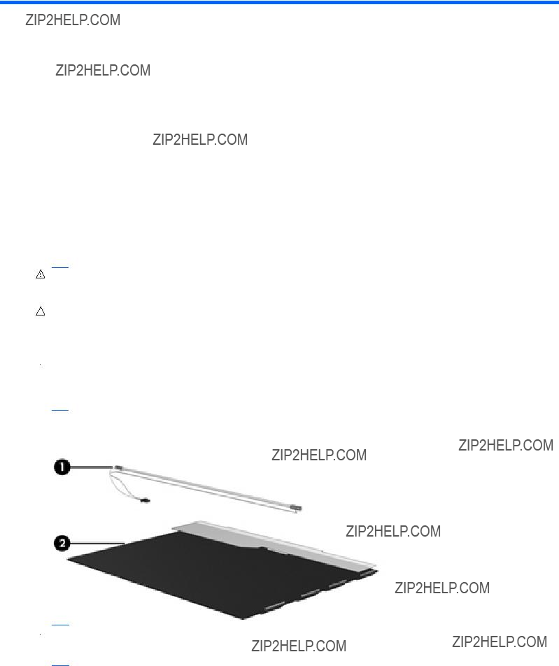
11 Recycling
Battery
When a battery has reached the end of its useful life, do not dispose of the battery in general household waste. Follow the local laws and regulations in your area for computer battery disposal.
Display
WARNING! The backlight contains mercury. Exercise caution when removing and handling the backlight to avoid damaging this component and causing exposure to the mercury.
CAUTION: The procedures in this chapter can result in damage to display components. The only components intended for recycling purposes are the liquid crystal display (LCD) panel and the backlight. When you remove these components, handle them carefully.
 NOTE: Materials Disposal. This HP product contains mercury in the backlight in the display assembly that might require special handling at
This section provides disassembly instructions for the display assembly. The display assembly must be disassembled to gain access to the backlight (1) and the liquid crystal display (LCD) panel (2).
 NOTE: The procedures provided in this chapter are general disassembly instructions. Specific details, such as screw sizes, quantities, and locations, and component shapes and sizes, can vary from one computer model to another.
Battery 135
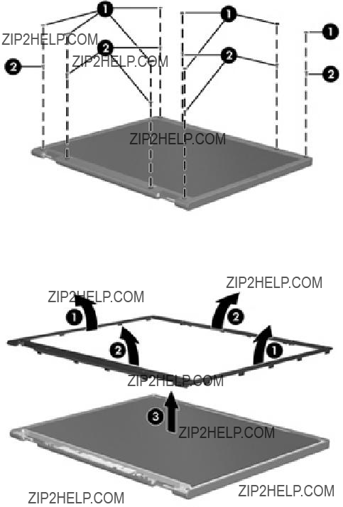
Perform the following steps to disassemble the display assembly:
1.Remove all screw covers (1) and screws (2) that secure the display bezel to the display assembly.
2.Lift up and out on the left and right inside edges (1) and the top and bottom inside edges (2) of the display bezel until the bezel disengages from the display assembly.
3.Remove the display bezel (3).
136 Chapter 11 Recycling
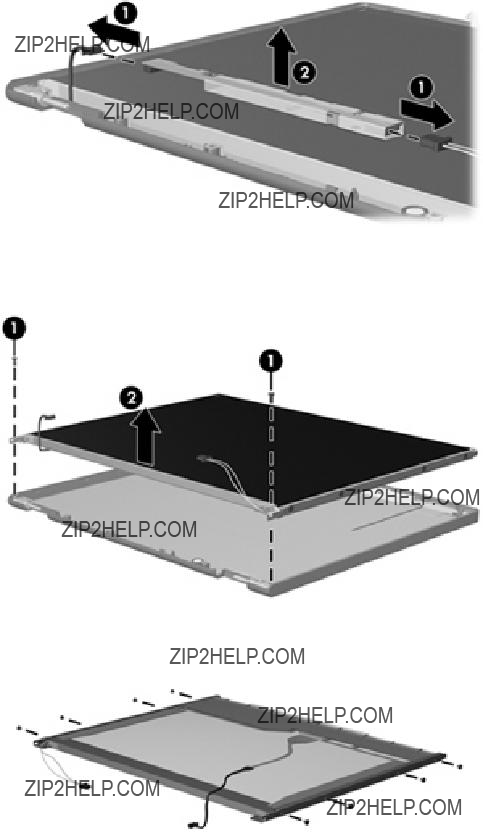
4.Disconnect all display panel cables (1) from the display inverter and remove the inverter (2).
5.Remove all screws (1) that secure the display panel assembly to the display enclosure.
6.Remove the display panel assembly (2) from the display enclosure.
7.Turn the display panel assembly upside down.
8.Remove all screws that secure the display panel frame to the display panel.
9.Use a
Display 137

10. Remove the display panel frame (2) from the display panel.
11.Remove the screws (1) that secure the backlight cover to the display panel.
12.Lift the top edge of the backlight cover (2) and swing it outward.
13.Remove the backlight cover.
14.Turn the display panel
138 Chapter 11 Recycling

15. Remove the backlight cables (1) from the clip (2) in the display panel.
16. Turn the display panel upside down.
WARNING! The backlight contains mercury. Exercise caution when removing and handling the backlight to avoid damaging this component and causing exposure to the mercury.
17. Remove the backlight frame from the display panel.
Display 139

18. Remove the backlight from the backlight frame.
19.Disconnect the display panel cable (1) from the LCD panel.
20.Remove the screws (2) that secure the LCD panel to the display rear panel.
21.Release the LCD panel (3) from the display rear panel.
22.Release the tape (4) that secures the LCD panel to the display rear panel.
23. Remove the LCD panel.
24. Recycle the LCD panel and backlight.
140 Chapter 11 Recycling
Index
Index 141
G
graphics, product description 1 grounding equipment and
methods 41
J jacks
Program Switcher 8 Windows applications 7 Windows logo 7
L
language support 85 latches, battery release 14 left TouchPad button,
identifying 5 lights
battery 9 caps lock 6 drive 9 power 9 webcam 13 wireless 10
memory module compartment, identifying 14
memory test 86
microphone
142 Index
restoring
HP Mi Restore Image
spare part number 23, 53 Rubber Kit, spare part number 28
S
Screw Kit contents 97
spare part number 28
Index 143